

Page 1

Installation Instructions
AllenĆBradley Redundant
Power Supplies
Cat. No. 1771ĆP4R and 1771ĆP6R
To the Installer
Important User Information
This document provides you with the following information:
For this information See page
Important user information 1
What this package contains 4
Tasks on installing your power supply module 4
How to interpret indicators 13
Flow charts for troubleshooting your power supply module 15
Power supply specifications 20
Because of the variety of uses for the products described in this
publication, those responsible for the application and use of these
products must satisfy themselves that all necessary steps have been
taken to assure that each application and use meets all performance
and safety requirements, including any applicable laws, regulations,
codes and standards. In no event will Rockwell Automation be
responsible or liable for indirect or consequential damage resulting
from the use or application of these products.
Any illustrations, charts, sample programs, and layout examples
shown in this publication are intended solely for purposes of
example. Since there are many variables and requirements associated
with any particular installation, Rockwell Automation does not
assume responsibility or liability (to include intellectual property
liability) for actual use based upon the examples shown in this
publication.
Allen–Bradley publication SGI–1.1, Safety Guidelines for
Application, Installation, and Maintenance of Solid–State Control
(available from your local Rockwell Automation office), describes
some important differences between solid–state equipment and
electromechanical devices that should be taken into consideration
when applying products such as those described in this publication.
Reproduction of the contents of this copyrighted publication, in
whole or part, without written permission of Rockwell Automation,
is prohibited.
Publication 1771-IN030B-EN-P - July 2002
Page 2

Allen-Bradley Redundant Power Supplies2
T
Throughout this publication, notes may be used to make you aware
of safety considerations. The following annotations and their
accompanying statements help you to identify a potential hazard,
avoid a potential hazard, and recognize the consequences of a
potential hazard.
WARNING
!
ATTENTION
!
IMPORTAN
Identifies information about practices or
circumstances that can cause an explosion in a
hazardous environment, which may lead to
personal injury or death, property damage, or
economic loss.
Identifies information about practices or
circumstances that may lead to personal injury or
death, property damage, or economic loss.
Identifies information that is critical for
successful application and understanding of the
product.
Publication 1771-IN030B-EN-P - July 2002
Page 3

Allen-Bradley Redundant Power Supplies 3
ATTENTION
!
Environment and Enclosure
This equipment is intended for use in a Pollution
Degree 2 industrial environment, in overvoltage
Category II applications (as defined in IEC
publication 60664–1), at altitudes up to 2000
meters without derating.
This equipment is considered Group 1, Class A
industrial equipment according to IEC/CISPR
Publication 11. Without appropriate precautions,
there may be potential difficulties ensuring
electromagnetic compatibility in other
environments due to conducted as well as radiated
disturbance.
This equipment is supplied as “open type”
equipment. It must be mounted within an
enclosure that is suitably designed for those
specific environmental conditions that will be
present, and appropriately designed to prevent
personal injury resulting from accessibility to live
parts. The interior of the enclosure must be
accessible only by the use of a tool. Subsequent
sections of this publication may contain additional
information regarding specific enclosure type
ratings that are required to comply with certain
product safety certifications.
See NEMA Standards publication 250 and IEC
publication 60529, as applicable, for explanations
of the degrees of protection provided by different
types of enclosures. Also, see the appropriate
sections in this publication, as well as the
Allen–Bradley publication 1770–4.1, (“Industrial
Automation Wiring and Grounding Guidelines”),
for additional installation requirements pertaining
to this equipment.
Publication 1771-IN030B-EN-P - July 2002
Page 4

Allen-Bradley Redundant Power Supplies4
What This Package
Contains
ATTENTION
!
Preventing Electrostatic Discharge
This equipment is sensitive to electrostatic
discharge, which can cause internal damage and
affect normal operation. Follow these guidelines
when you handle this equipment:
• Touch a grounded object to discharge potential
static.
• Wear an approved grounding wriststrap.
• Do not touch connectors or pins on component
boards.
• Do not touch circuit components inside the
equipment.
• If available, use a static–safe workstation.
• When not in use, keep modules in appropriate
static–safe packaging.
When you receive your 1771-P4R or -P6R power supply, you should
see the following in the box:
• one 1771-P4R or 1771-P6R power-supply module
• one 3-position terminal block (attached to module)
• one 5-position terminal block (attached to module)
• one redundant cable
Installing the
PowerĆsupply Module
To install your power supply module you perform these tasks:
To perform this task See page
set the jumpers
set the I.D. selection and configuration switches 6
place the power supplies 7
connect the redundancy cables 8
wire the alarm relay 8
connect input power 10
5
Publication 1771-IN030B-EN-P - July 2002
Page 5

Allen-Bradley Redundant Power Supplies 5
T
Set the Jumpers
Each power supply module has two jumpers located at the back of
the power supply near the edge connectors. The jumper selection
provides the proper voltage regulation for the different power supply
configurations. The power supply can be configured to support local
or remote sensing by setting the jumpers.
1. Locate the power supply jumpers on the back edge of the module
near the gold-plated edge connectors:
19965
2. Position the power supply module so that the jumpers and pins
are facing upward.
3. Use needle nose pliers to position the jumpers as shown in
this table.
For this configuration Set jumpers to
All power supplies in a powerĆsupply
chassis (1771ĆPSC) connected to an
I/O chassis.
All other configurations.
(These power supplies are shipped with
jumpers set to the left.)
right position
left position
To avoid system malfunctions, set the jumpers
IMPORTAN
of power supplies in 1771 I/O chassis to the
left position.
Publication 1771-IN030B-EN-P - July 2002
Page 6
Allen-Bradley Redundant Power Supplies6
A
B
C
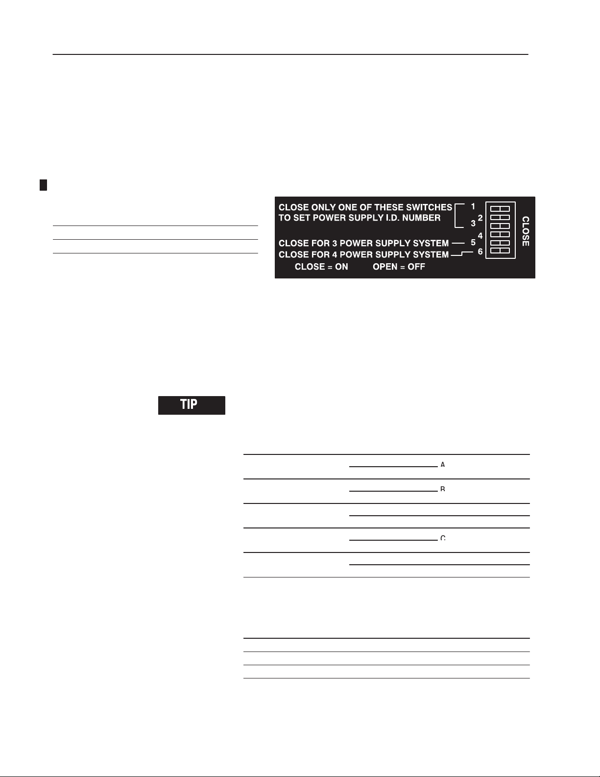
Switches Are set
1, 2, 3, 4
5, 6 based on the configuration zone
for the power supply identification number
Set the I.D. Selection and Configuration Switches
Each power supply in a redundant system must be assigned a
different identification number. To do this, you must set the I.D.
selection switches located on the left side of the module
(shown below). A cutout in the metal cover of the module provides
access to these switches.
I.D. Selection Switch
To set the switches:
"
1. Close the I.D selection switch (1, 2, 3, or 4) that represents the
number you selected for that power supply.
2. Determine the configuration zone being used so you can set
switches 5 and 6.
To determine the configuration zone, you must know the maximum
chassis current draw and the ambient air temperature of the chassis.
Maximum Current Draw (A) Ambient Temperature Configuration Zone
0Ć8
8Ć14
14Ć16
16Ć20
20Ć24
55°C
60°C
55°C
60°C
55°C B
60°C C
55°C
60°C
55°C C
60°C
not permitted
3. Use the following table to position switches 5 and 6 based on the
configuration zone you determined.
If Configuration Zone Is Set Switches
A
B 5 CLOSED and 6 OPEN
C 5 OPEN and 6 CLOSED
Publication 1771-IN030B-EN-P - July 2002
5 and 6 OPEN
Page 7
Allen-Bradley Redundant Power Supplies 7
T
Place the Power Supplies
ATTENTION
!
You can place these power supply modules into any I/O module slot
in any current chassis (1771-A1B, -A2B, -A3B, -A3B1,
-A4B, -PSC).
The primary requirement for placing redundant power supplies is the
need to allocate 2 to 4 adjacent slots in your 1771 I/O chassis for
the modules.
IMPORTAN
WARNING
!
Turn off the power supply module before
removing it from or inserting it into a chassis.
Failure to observe this warning could alter
processor memory, damage module circuitry, and
cause unintended operation which could possibly
cause injury to personnel.
You cannot use the 1771-P4R, -P6R power
supplies with series A 1771 I/O chassis.
When you insert or remove the module while
backplane power is on, or you connect or
disconnect the wiring with field power applied, an
electrical arc can occur. This could cause an
explosion in hazardous location installations. Be
sure power is removed or the area is nonhazardous
before proceeding.
The power supply is a modular component of the 1771 I/O system
requiring a properly installed system chassis. Refer to publication
1771–IN075 for detailed information on acceptable chassis, and
proper installation and grounding requirements. Limit the adjacent
slot power dissipation to 10W maximum.
Publication 1771-IN030B-EN-P - July 2002
Page 8
Allen-Bradley Redundant Power Supplies8
Cable pt. no. A-B 941201-02
(supplied with power supply)
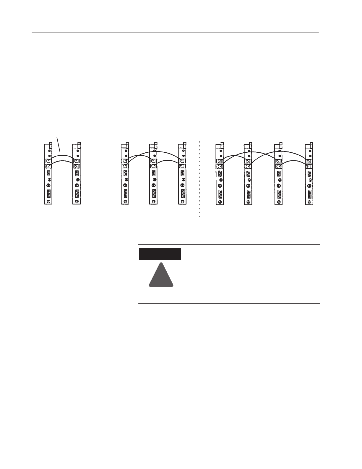
Connect the Redundancy Cables
The power supply redundancy cables (A–B pt. no. 941201–02) allow
the power supplies to communicate load-sharing data. The two
connectors on each supply are in parallel to permit three or four
supplies to be daisy-chained together in a redundant system.
To connect the cables:
1. Connect the redundancy cable between the connectors labeled P/S
REDUNDANT on the power supply as shown below.
Connecting the Redundancy Cables for a 2, 3, or 4 Supply System
2 powerĆsupply system 3 powerĆsupply system 4 powerĆsupply system
2. Loop the cable over the top of the I/O chassis to avoid picking up
signals induced from I/O wiring.
WARNING
!
When you insert or remove the module while
backplane power is on, or you connect or
disconnect the alarm relay, ac power, or
redundancy cable with field power applied, an
electrical arc can occur. This could cause an
explosion in hazardous location installations. Be
sure power is removed or the area is nonhazardous
before proceeding.
Wire the Alarm Relay
A 3-position terminal block labeled RELAY on the front panel of the
module provides you with a means of communicating the status of
the power supply to some alarm device. The contacts on the relay
are rated at 1/6 HP, 250V ac, 1 Amp, 30V dc maximum.
The relay energizes within 0.5 seconds after sufficient input power is
applied and no error conditions have been encountered. The error
conditions include 5V output overvoltage, undervoltage, or
overcurrent and internal reference error. The relay de-energizes
within 10 seconds following detection of an error condition or loss of
power. Contact bounce may occur for 100 ms.
Publication 1771-IN030B-EN-P - July 2002
Page 9

Allen-Bradley Redundant Power Supplies 9
The terminal block has three lines:
• NC (Normally Closed)
• COM (Common)
• NO (Normally Open)
Using the normally closed side of the block will keep the relay
contacts open until unit failure (when it will close). Using the
normally open side of the relay will keep the relay contacts closed
until unit failure (when it will open).
To wire the relay, place the incoming line in the NC or NO position
and out the COM position to the load. Any spare point on an input
module can be connected and used for signaling by the relay.
To connect the wiring to the 3–terminal relay connector, proceed as
follows:
A. Strip 0.35 inches (9cm) of insulation off the wire.
B. Spring the clip open to insert the wire, using a wedge-tipped
tool, such as a small screwdriver.
• If you leave the terminal block plugged into the supply,
insert the tool parallel to the wire (push straight in).
Insert wire here
This side plugs
into the connector
on module
Place tool here
19966A
• If you remove the terminal block and lay it on a flat
surface, insert the tool perpendicular to the wire (push
straight down).
Insert wire here
This side plugs
into the connector
on module.
Place tool here
C. After making the wiring connections, re-insert the terminal
block into the front plate on the processor.
19966B
Publication 1771-IN030B-EN-P - July 2002
Page 10

Allen-Bradley Redundant Power Supplies10
Alarm Relay and AC Power Connections
"
Connect Input Power
The following figure shows the overall configuration of the ac power
connections.
The two undesignated terminals do not connect to any electrical
circuit on the module. Each of the three functional terminals accepts
a single 14-AWG wire max.
To correctly connect the wire to the terminal you connect the wires
to the terminal in this order:
• connect the high side of the power source to the L1 terminal of
the power supply
• connect the low side of the power source to the L2 or N (neutral)
terminal of the power supply
• connect the GND (ground) terminal of the power supply to the
central ground bus in the enclosure
Publication 1771-IN030B-EN-P - July 2002
Page 11

Allen-Bradley Redundant Power Supplies 11
"
ATTENTION
!
You can connect these wires while the terminal block is plugged into
the supply, or you can remove the terminal block to lay it on a flat
surface to connect these wires. To remove the terminal block, pull it
straight out out from the receptacle on the module.
WARNING
!
Pay close attention to the ac GND and L1
connections when wiring the terminal block. An
error here could cause the ac power to be applied
to the chassis.
Check that the input voltage rating on the power
supply front panel agrees with the available power
source. Application of the incorrect line voltage
can cause severe power supply damage.
When you insert or remove the module while
backplane power is on, or you connect or
disconnect the alarm relay, ac power, or
redundancy cable with field power applied, an
electrical arc can occur. This could cause an
explosion in hazardous location installations. Be
sure power is removed or the area is nonhazardous
before proceeding.
To connect wiring to the 5–terminal ac power block, proceed as
follows:
1. Connect the power cord to the ac connector (120V or 220V) of
the power supply module.
A. Strip 0.35 inches (9cm) of insulation off the wire.
B. Spring the clip open to insert the wire, using a wedge-tipped
tool, such as a small screwdriver.
• If you leave the terminal block plugged into the supply,
insert the tool parallel to the wire (push straight in).
Insert wire here
This side plugs
into the connector
on module
Place tool here
19966
Publication 1771-IN030B-EN-P - July 2002
Page 12

Allen-Bradley Redundant Power Supplies12
• If you remove the terminal block and lay it on a flat
surface, insert the tool perpendicular to the wire (push
straight down ).
Insert wire here
This side plugs
into the connector
on module.
Place tool here
19966
C. After making the wiring connections, re-insert the terminal
block into the front plate on each processor.
Make sure the plug is completely inserted
and the locking prongs are engaged.
Once you have completed the tasks up to this point, you can turn the
power switches ON. Turn all the power switches on at the same
time. If everything is set up correctly, all P/S ACTIVE (green)
indicators will be on and all NON REDUNDANT SYSTEM
(yellow) indicators will be off.
Publication 1771-IN030B-EN-P - July 2002
Page 13

Allen-Bradley Redundant Power Supplies 13
Interpreting the Power
Supply Indicators
Your power supply has two indicators located in the upper half of the
module front panel.
The top indicator is yellow and is labeled NON REDUNDANT
SYSTEM. This indicator tells you that the number of supplies in
operation is below the number required for redundant operation. The
yellow indicators in a redundant system operate together; they are
either all on or all off.
The lower indicator is green and is labeled P/S ACTIVE. The
following table shows how to interpret this indicator.
If P/S ACTIVE
indicator is
ON
OFF The supply has detected one of the following conditions:
Then
This power supply is operating normally and a sufficient number of
power supplies is operational for the system configuration.
• dc overvoltage (the supply shuts down)
• dc undervoltage (the supply shuts down)
• dc overcurrent (the supply shuts down)
• power switch turned off (the supply is turned off)
• ac undervoltage
• insufficient number of operational power supplies for the system
configuration
When the P/S ACTIVE indicator is off because of an ac undervoltage
or because an insufficient number of supplies
is operational, the power supply may continue to deliver
output power.
Troubleshoot Your Power
Supplies
When you troubleshoot your power supplies, you may be required to
remove and replace the power supply while power is still applied to
the chassis.
For information on See page
Removing the power supply
Inserting the power supply 14
Troubleshooting a single power supply 15
Troubleshooting multiple power supplies 16
14
Publication 1771-IN030B-EN-P - July 2002
Page 14

Allen-Bradley Redundant Power Supplies14
Removing the Power Supply
WARNING
!
1. Flip the POWER switch on the front panel to the Off position,
only on the unit to be removed.
2. Remove the ac input terminal block, the alarm relay terminal
block, and the redundant cables only from the unit to be
removed.
3. Slide the unit out of the chassis and note the following settings:
When you insert or remove the module while
backplane power is on, or you connect or
disconnect the alarm relay, ac power, or
redundancy cable with field power applied, an
electrical arc can occur. This could cause an
explosion in hazardous location installations. Be
sure power is removed or the area is nonhazardous
before proceeding.
• I.D selection switch setting (1 through 4)
• configuration switch setting (5 and 6)
• jumper setting (local or remote sensing)
• input voltage rating on the front panel near the ac input
connector
You will set the replacement unit to the same settings.
Inserting the Power Supply
1. Configure the supply to the same settings as the unit removed.
2. Flip the POWER switch on the front panel to the Off position.
3. Insert the module completely into the slot in the chassis.
4. Connect redundant cables, alarm relay terminal block, and ac
input terminal block.
5. Flip the POWER switch to the On position.
Publication 1771-IN030B-EN-P - July 2002
Page 15

Allen-Bradley Redundant Power Supplies 15
Troubleshooting a Single Power Supply
If you have a single power supply installed in an I/O chassis and
its P/S ACTIVE indicator is off, follow the troubleshooting
flowchart below.
Turn off the power supply and wait 5 seconds.
Check I.D. Selection and Configuration switch settings.
Then turn on the power supply.
P/S Active
ON?
no
Turn off the power supply and wait 5 seconds.
Pull the power supply half way out of the chassis and
turn it on to test it without a load.
P/S Active
Off?
no
Turn off the power supply and wait 5 seconds.
Firmly seat the power supply into the backplane then
turn on the power supply again.
P/S Active
P/S Active
ON?
ON?
no
yes
Done
yes
If ac voltage is OK, replace
the power supply.
yes
Done
Done
Try replacing the power supply with a known good
power supply.
P/S Active
ON?
no
Try replacing the I/O modules (one of them could be
overloading the power supply).
yes
Done
Publication 1771-IN030B-EN-P - July 2002
Page 16

Allen-Bradley Redundant Power Supplies16
Troubleshooting Multiple Power Supplies
If you have multiple power supplies, refer to the flowcharts on the
next three pages to help you troubleshoot when the following
problems occur.
Problem 1
One or more (but not all) of the supplies in the redundant system has
its P/S ACTIVE indicator off. (Depending on the system
configuration, NON REDUNDANT SYSTEM indicators may or
may not be on.)
Turn off the power supply and wait 5 seconds.
Then turn on the power supply.
no
no
no
yes
Done
yes
If ac voltage is OK, replace
the power supply.
yes
Done
Done
P/S Active
ON?
Turn off the power supply and wait 5 seconds.
Pull the power supply half way out of the chassis, open
switches 5 and 6, and remove redundant cables.
Turn the power supply on to test it without a load.
P/S Active
Off?
Turn off the power supply and wait 5 seconds.
Reset switches 5 and 6 to original positions and reinsert
the redundant cables. Firmly seat the power supply into
the backplane, then turn on the power supply again.
P/S Active
P/S Active
ON?
ON?
Publication 1771-IN030B-EN-P - July 2002
Try replacing the power supply with a known good
power supply.
no
yes
Done
P/S Active
ON?
Turn off the power supply and check the redundant
cables for continuity and shorts. These shielded
6Ćconductor cables are 1:1.
Page 17

Allen-Bradley Redundant Power Supplies 17
Problem 2
All the supplies in the redundant system have their P/S ACTIVE
indicators off. The NON REDUNDANT SYSTEM LED may or
may not be on.
Turn off the power supply and wait 5 seconds. Then turn on the power
supplies simultaneously.
no
no
no
yes
Done
If ac voltage is OK, replace the
yes
power supply, but do not turn
the ac power switch on.
Continue to test other supplies.
yes
Done
Done
P/S Active
ON?
Turn off the power supplies and wait 5 seconds. Test each power supply
individually. Pull the first power supply half way out of the chassis. Open
switches 5 and 6 and remove the redundant cables. Turn on the power supply
to test it without a load. Repeat for the other power supplies.
P/S Active
Off?
Turn off the power supply and wait 5 seconds. Reset switches 5 and 6 to original
positions and reinsert the redundant cables. Firmly seat the power supply into the
backplane, then turn on the power supply again.
P/S Active
P/S Active
ON?
ON?
Using a known good supply, swap out each power supply with the known good
power supply. Be sure to correctly set the I.D. switches.
P/S Active
ON?
Turn off the power supply and check the redundant cables for continuity and
shorts. These shielded 6Ćconductor cables are 1:1.
P/S Active
ON?
Try replacing the I/O modules (one of them could be overloading the supplies).
yes
Done
no
yes
Done
no
Publication 1771-IN030B-EN-P - July 2002
Page 18

Allen-Bradley Redundant Power Supplies18
Problem 3
All P/S ACTIVE indicators show that the power supplies are OK,
but one or more NON REDUNDANT SYSTEM indicators are on,
indicating the desired redundancy is not available.
Check the redundant cables for continuity and
shorts. These shielded 6Ćconductor cables are 1:1.
no
no
yes
Done
If ac voltage is OK, replace the
yes
power supply, but do not turn
the ac power switch on.
Continue to test other supplies.
P/S Active
ON?
Check switches 5 and 6 on all supplies to make
sure settings on each are the same.
P/S Active
Off?
Try replacing the power supply with a known good
power supply.
Publication 1771-IN030B-EN-P - July 2002
Page 19

Allen-Bradley Redundant Power Supplies 19
:
The following information applies when operating this equipment in
hazardous locations:
Products marked CL I, DIV 2, GP A, B, C, D" are suitable for use in Class I Division 2
Groups A, B, C, and D Hazardous Locations and nonhazardous locations only. Each
product is supplied with markings on the rating nameplate indicating the hazardous location
temperature code. When combining products within a system, the most adverse
temperature code (lowest T" number) may be used to help determine the overall
temperature code of the system. Combinations of equipment in your system are subject to
investigation by the local Authority Having Jurisdiction at the time of installation.
WARNING
EXPLOSION HAZARD -
• Do not disconnect equipment unless power has been
removed or the area is known to be nonhazardous.
• Do not disconnect connections to this equipment unless
power has been removed or the area is known to be
nonhazardous. Secure any external connections that mate
to this equipment by using screws, sliding latches,
!
threaded connectors, or other means provided with this
product.
• Substitution of components may impair suitability for Class
I, Division 2.
• If this product contains batteries, they must only be
changed in an area known to be nonhazardous.
Informations sur l'utilisation de cet équipement en environnements dangereux
Les produits marqués CL I, DIV 2, GP A, B, C, D ne conviennent que une utilisation en
environnements de Classe I Division 2 Groupes A, B, C, D dangereux et non dangereux.
Chaque produit est livré avec des marquages sur sa plaque d'identification qui indiquent le
code de température pour les environnements dangereux. Lorsque plusieurs produits sont
combinés dans un systéme, le code de température le plus défavorable (code de
température le plus faible) peut eatre utilisé pour déterminer le code de température global
du systéme. Les combinaisons d'equipements dans le systéme sont sujettes à inspection
par les autorités locales qualifiées au moment de l'installation.
AVERTISSEMENT
RISQUE D'EXPLOSION -
• Couper le courant ou s'assurer que l'environnement est
classé non dangereux avant de débrancher l'équipement.
• Couper le courant ou s'assurer que l'environnement est
classé non dangereux avant de débrancher les
connecteurs. Fixer tous les connecteurs externes reliés à
cet équipement à
!
l'aide de vis, loquets coulissants, connecteurs filetés ou
autres moyens fournis avec ce produit.
• La substitution de composants peut rendre cet équipement
inadapté à une utilisation en environnement de Classe 1,
Division 2.
• S'assurer que l'environnement est classé non dangereux
avant de changer les piles.
Publication 1771-IN030B-EN-P - July 2002
Page 20

Allen-Bradley Redundant Power Supplies20
Specifications
1771-P4R 1771-P6R
Input Voltage 120V ac, 50-60Hz, 1A 220V ac, 50-60Hz, 0.5A
Input Voltage Range 97-132V ac 194-240V ac
Module Location 1771ĆA1B, thru ĆA4B or later I/O chassis
Output Voltage 5V dc, 8A (See Derating Curve)
Maximum System Output Current at
o
C using N+1 Redundancy
60
Power Dissipation 16 Watts (max.)
Power Dissipation - adjacent slot 10 Watts (max.)
Thermal Dissipation 47.8 BTU/hr (max.), 6.9 BTU/hr (min.)
Backplane Current 300mA @ 5V dc +5%
Isolation Voltage Tested to withstand 1000V for 60s.
Redundancy Cable A-B pt. no. 941201-02
Conductors Wire Size
Category
Branch Circuit Protection
2
Environmental Conditions
Operating Temperature IEC 60068-2-1 (Test Ad, Operating Cold)
Storage Temperature IEC 60068-2-1 (Test Ab, Unpackaged, Nonoperating Cold)
Relative Humidity IEC 60068-2-30 (Test Db, Unpackaged, Nonoperating Damp Heat)
Shock
Operating
Nonoperating
Vibration IEC 60068-2-6 (Test Fc, Operating)
Enclosure Type Rating None (open-style)
Fuse 1.5A, 250V fuse - Bussman MDL 1.5, Littelfuse 31301.5,
Wiring Blocks ac power
alarm relay
Weight 2 lbs. (0.85kg)
Alarm Relay Rating 250V ac, 1/6 HP; 1A, 30V dc
Specifications continued on next page.
8A (2 unit system)
14A (3 unit system)
20A (4 unit system)
14 AWG (2.5mm2) stranded copper rated at 60oC or greater
3/64 inch (1.2mm) insulation (max)
1
1
15A maximum (user provided)
IEC 60068-2-2 (Test Bd, Operating Dry Heat)
IEC 60068-2-14 (Test Nb, Operating Thermal Shock)
32 to 140°F(0
o
to 60oC)
IEC 60068-2-2 (Test Bb, Unpackaged, Nonoperating Dry Heat)
IEC 60068-2-14 (Test Na, Unpackaged, Nonoperating Thermal
Shock)
-13 to 176°F (25 to 80
o
C)
5 to 95%, noncondensing
IEC 60068-2-27 (Test Ea, Unpackaged Shock)
30g
50g
2g @ 10-500Hz
IEC 127 (blue)
A-B PN941274-55 (Wago PN231-002/027-000)
A-B PN941274-03 (Wago PN231-203/000-008)
Publication 1771-IN030B-EN-P - July 2002
Page 21

Allen-Bradley Redundant Power Supplies 21
1771-P6R1771-P4R
Certifications
(when product is marked)
1
You usethis conductor category information for planning conductor routing as described in publication 1770Ć4.1, Industrial
Automation Wiring and GroundingGuidelines.
2
Provided in all ungrounded mainsconnections
3
See the Product Certification link at www.ab.com for Declarations of Conformity, Certificates and other certification details
UL UL Listed Industrial Control Equipment
c-UL UL Listed for Class I,Division 2 Group A, B, C, D
Hazardous Locations certified for Canada
3
European Union 89/336/EEC EMC Directive,
CE
compliant with:
EN 50082-2, Industrial Immunity
EN 61000-6-2, Industrial Immunity
EN 61000-6-4, Industrial Emissions
EN 61326; Meas./Control/Lab., Industrial Requirements
European Union 73/23/EEC LVD Directive,
compliant with:
EN 61131-2, Programmable Controllers
3
Australian Radiocommunications Act, compliant with:
C-Tick
AS/NZS 2064, Industrial Emissions
.
Derating Curve for the 1771-P4R, -P6R
9
8
7
6
5
4
Output Current (A)
3
2
1
0
010 203040 5060
55
AmbientTemperature (oC)
Publication 1771-IN030B-EN-P - July 2002
Page 22

Allen-Bradley Redundant Power Supplies22
Publication 1771-IN030B-EN-P - July 2002
Page 23

Allen-Bradley Redundant Power Supplies 23
Publication 1771-IN030B-EN-P - July 2002
Page 24

Allen-Bradley Redundant Power Supplies24
Publication 1771-IN030B-EN-P - July 2002
Supersedes publication 1771Ć5.30 - December 1995
Publication 1771-IN030B-EN-P - July 2002
Copyright 2002 Rockwell Automation, Inc. Printed in USA
PN 957689-79
 Loading...