

Page 1
Installation Instructions
AC (12Ć120V) Output Module
Cat. No. 1771ĆOAD Series C
To The Installer
Important User Information
This document provides information on:
To See page
Important User Information 1
Important PreĆinstallation Considerations 4
Calculate Power Requirements 5
Select the Mode of the FuseĆblown Jumper 5
Key the Backplane Connector 7
Install the Module and Field Wiring Arm 8
Connect Wiring to the Output Module 9
Troubleshooting 11
For this reference information See page
Interpreting the Status Indicators 11
Replacing the Fuse 12
Hazardous Locations 13
Specifications 14
Because of the variety of uses for the products described in this
publication, those responsible for the application and use of these
products must satisfy themselves that all necessary steps have been
taken to assure that each application and use meets all performance
and safety requirements, including any applicable laws, regulations,
codes and standards. In no event will Rockwell Automation be
responsible or liable for indirect or consequential damage resulting
from the use or application of these products.
Any illustrations, charts, sample programs, and layout examples
shown in this publication are intended solely for purposes of
example. Since there are many variables and requirements associated
with any particular installation, Rockwell Automation does not
assume responsibility or liability (to include intellectual property
liability) for actual use based upon the examples shown in this
publication.
Publication 1771ĆIN024B-EN-P - November 2002
Page 2
AC (12-120V) Output Module2
T
Allen–Bradley publication SGI–1.1, Safety Guidelines for
Application, Installation, and Maintenance of Solid–State Control
(available from your local Rockwell Automation office), describes
some important differences between solid–state equipment and
electromechanical devices that should be taken into consideration
when applying products such as those described in this publication.
Reproduction of the contents of this copyrighted publication, in
whole or part, without written permission of Rockwell Automation,
is prohibited.
Throughout this publication, notes may be used to make you aware
of safety considerations. The following annotations and their
accompanying statements help you to identify a potential hazard,
avoid a potential hazard, and recognize the consequences of a
potential hazard.
WARNING
!
ATTENTION
!
IMPORTAN
Identifies information about practices or
circumstances that can cause an explosion in a
hazardous environment, which may lead to
personal injury or death, property damage, or
economic loss.
Identifies information about practices or
circumstances that may lead to personal injury or
death, property damage, or economic loss.
Identifies information that is critical for
successful application and understanding of the
product.
Publication 1771ĆIN024B-EN-P - November 2002
Page 3

AC (12-120V) Output Module 3
ATTENTION
!
Environment and Enclosure
This equipment is intended for use in a Pollution
Degree 2 industrial environment, in overvoltage
Category II applications (as defined in IEC
publication 60664–1), at altitudes up to 2000
meters without derating.
This equipment is considered Group 1, Class A
industrial equipment according to IEC/CISPR
Publication 11. Without appropriate precautions,
there may be potential difficulties ensuring
electromagnetic compatibility in other
environments due to conducted as well as radiated
disturbance.
This equipment is supplied as “open type”
equipment. It must be mounted within an
enclosure that is suitably designed for those
specific environmental conditions that will be
present, and appropriately designed to prevent
personal injury resulting from accessibility to live
parts. The interior of the enclosure must be
accessible only by the use of a tool. Subsequent
sections of this publication may contain additional
information regarding specific enclosure type
ratings that are required to comply with certain
product safety certifications.
See NEMA Standards publication 250 and IEC
publication 60529, as applicable, for explanations
of the degrees of protection provided by different
types of enclosures. Also, see the appropriate
sections in this publication, as well as the
Allen–Bradley publication 1770–4.1, (“Industrial
Automation Wiring and Grounding Guidelines”),
for additional installation requirements pertaining
to this equipment.
Publication 1771ĆIN024B-EN-P - November 2002
Page 4

AC (12-120V) Output Module4
PreĆinstallation
Considerations
ATTENTION
!
Preventing Electrostatic Discharge
This equipment is sensitive to electrostatic
discharge, which can cause internal damage and
affect normal operation. Follow these guidelines
when you handle this equipment:
• Touch a grounded object to discharge potential
static.
• Wear an approved grounding wriststrap.
• Do not touch connectors or pins on component
boards.
• Do not touch circuit components inside the
equipment.
• If available, use a static–safe workstation.
• When not in use, keep modules in appropriate
static–safe packaging.
The 1771-OAD Series C module is compatible with all chassis
except 1771-A1, 1771-A2 and 1771-A4 chassis. Make sure no other
output module or single card block transfer module is placed in the
same module group when using 2-slot addressing. Any discrete input
module may be used within the same module group.
Using the 1771ĆOAD Series C Module with HalfĆwave Rectifying
Load Devices (single diode) and Indicator Lights
This module uses zero-crossing technology to allow turn-on when
the output voltage is less than a specified voltage (typically 40 to
50V). This greatly reduces the stress on contacts and other devices
that are sensitive to current surges.
• When using this output module with a device that includes a
single diode in series with the load, place a shunt resistor (39K
ohm, 1W) across the load. This resistor allows proper output
operation.
The shunt resistor may cause LED indicators to glow when the
output is turned off. In this case, use an incandescent lamp in
place of the LED.
• When using a full-wave rectified device, the device may not turn
off when the output is deenergized. Add a 2.5K ohm, 10W
resistor in parallel with the device to provide proper operation.
• If 24V ac incandescent indicator lights appear dim when used
with the Series C module, place a 2.5K ohm, 10W resistor in
parallel with the indicator. This will restore full brightness.
Publication 1771ĆIN024B-EN-P - November 2002
Page 5
AC (12-120V) Output Module 5
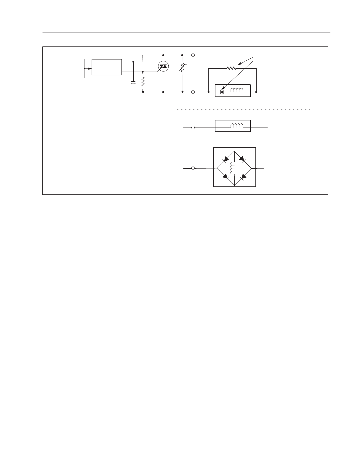
Simplified Circuit Diagram
Control
1. When L2 is positive with respect to
L1, capacitor C1 is charged.
2. When the polarity switches, the diode
prevents C1 from discharging.
3. With C1 charged (possibly up to line
voltage), the zeroĆcrossing optoĆtriac sees
that voltage, and won't turn on.
4. The shunt resistor allows a bleedĆoff of
the voltage on the capacitor, allowing the
circuit to function properly.
ZeroĆCrossing
OptoĆisolation
Calculate Power
Requirements
C1
L1
39KΩ
Load
Load
Load
Single rectifying diode
in series with load.
Shunt Resistor required
L2
No rectifying diode.
Shunt Resistor NOT required
L2
Full wave rectifier.
Shunt Resistor NOT required
L2
Note: A resistor may be
required if the load is less
than 50mA.
Your module receives its power through the 1771 I/O chassis
backplane from the chassis power supply. The module requires
295mA from the output of this supply. Add this to the requirements
of all other modules in the I/O chassis to prevent overloading the
chassis backplane and/or chassis power supply.
Select the Mode of the
Fuse-Blown Jumper
The fuse-blown jumper has two modes:
• the preset, standard (STD) mode – displays the fuse status on
the red fuse-blown status indicator
• the customer side indication (CSI) mode – displays the fuse
status in the input image table and on the red fuse-blown status
indicator.
This mode configures the module as a 16 point output module
that uses both the output and input image data tables of your
controller. When a fuse blows, all 16 bits in the associated input
image table will turn on (1).
For example, if you install the module in a PLC-5 system and
address the module as O:012, then the fuse status bits are in
I:012.
To monitor the status of the module fuse, make certain that your user
program monitors the module’s input image table for ‘‘on” bits.
Publication 1771ĆIN024B-EN-P - November 2002
Page 6

AC (12-120V) Output Module6
ATTENTION
Do not put the module jumper in CSI mode when
you use this module in a complementary mode.
Your system will not operate properly.
!
To change the fuse blown jumper to the CSI mode:
1. Locate the fuse-blown jumper at the top-right edge of the module
circuit board, as shown.
TopĆright edge of circuit board
STD
Fuse Blown Jumper
(shown in preset
STD position)
2. Use your finger to slide the jumper off the STD position (the
middle post and the left post).
3. Carefully reposition the jumper by sliding it onto the CSI position
(the middle post and the right post).
CSI
12636ĆI
Publication 1771ĆIN024B-EN-P - November 2002
Page 7

AC (12-120V) Output Module 7
Key the Backplane
ATTENTION
Connector
Place your module in any slot in the chassis
except the leftmost slot, which is reserved for
processors or adapters.
ATTENTION
!
Observe the following precautions
when inserting or removing keys:
• insert or remove keys with your
fingers
• make sure that key placement is
correct
Incorrect keying or the use of a tool
can result in damage to the
backplane connector and possible
system faults.
A module inserted into a wrong slot could be
damaged by improper voltages connected through
the wiring arm. Use keying bands to prevent
damage to the module.
!
Position the keying bands in the backplane connectors to correspond to
the key slots on the module.
I/O chassis
Place the keying bands:
- between 10 and 12
- between 20 and 22
Upper Connector
You can change the position of these bands if
subsequent system design and rewiring makes
insertion of a different type of module necessary.
11022ĆI
Publication 1771ĆIN024B-EN-P - November 2002
Page 8

AC (12-120V) Output Module8
Install the Module and Field
Wiring Arm
1771ĆA1B, ĆA2B, ĆA3B, ĆA3B1, ĆA4B I/O chassis
locking tab
WARNING
!
ATTENTION
!
When you insert or remove the module while
backplane power is on, or you connect or
disconnect the wiring arm with field power
applied, an electrical arc can occur. This could
cause an explosion in hazardous location
installations. Be sure power is removed or the area
is nonhazardous before proceeding.
Remove power from the 1771 I/O chassis
backplane and field wiring arm before removing
or installing an I/O module.
• Failure to remove power from the backplane or
wiring arm could cause module damage, degradation of performance, or injury.
• Failure to remove power from the backplane
could cause injury or equipment damage due to
possible unexpected operation.
1771ĆA1B, ĆA2B, ĆA3B1, ĆA4B Series B I/O chassis
locking bar pin
locking bar
card guides
Snap the chassis latch over
the top of the module to secure it.
Attach the wiring arm (1771ĆWH) to the horizontal
bar at the bottom of the I/O chassis.
The wiring arm pivots upward and connects with
the module so you can install or remove the
module without disconnecting the wires.
The 1771–OAD series C module is a modular component of the
1771 I/O system requiring a properly installed system chassis. Refer
to publication 1771–IN075 for detailed information on acceptable
chassis, proper installation and grounding requirements. Limit the
maximum adjacent slot power dissipation to 10W maximum.
module
Swing the chassis locking bar down into place to secure
the modules. Make sure the locking pins engage.
horizontal bar
remove
install
card guides
module
19809
wiring arm
1771ĆWH
17643
Publication 1771ĆIN024B-EN-P - November 2002
Page 9

Connect Wiring to the
Output Module
AC (12-120V) Output Module 9
Make wiring connections to the 21 terminal field wiring arm (cat. no.
1771-WH) shipped with the module.
You must supply ac (L1) at terminals A through D
on the field wiring arm, as shown. You need four
ac connections to accommodate the total required
surge rating on the module without overstressing
any single connection on the field wiring arm.
Jumper all ac (L1) connections together to prevent
module damage.
L1
L1
L1
L1
Output 00
Output 01
Output 02
Output 03
Output 04
Output 05
Output 06
Output 07
Output 10
Output 11
Output 12
Output 13
Output 14
Output 15
Output 16
Output 17
L2/optional
A
B
C
D
00
01
02
03
04
05
06
07
10
11
12
13
14
15
16
17
E
Output
Device
L1
ac High
L2
ac Low
Field Wiring Arm
Cat. No. 1771ĆWH
(Actual wiring runs in this direction.)
12223-I
You must supply ac at terminals A through D on the wiring arm. You
need four ac connections to accommodate the total required surge
rating on the module without overstressing any single connection on
the field wiring arm. Jumper all ac connections together to prevent
module damage. Connect terminal E to ac Low.
ATTENTION
Observe proper polarity, as indicated in the
connection diagram with dc power connections.
Reverse polarity, or application of ac voltage,
could damage the module.
!
Publication 1771ĆIN024B-EN-P - November 2002
Page 10

AC (12-120V) Output Module10
Driving an Input Module with an Output Module
You can use an AC (120V) Output Module (cat. no. 1771ĆOAD)
to directly drive terminals on an AC/DC (120V) Input Module
(cat. no. 1771ĆIAD) as shown below.
You can also use a 1771ĆOAD Output module to drive an AC/DC
(120V) Input Module (cat. no. 1771ĆIA) but you must connect one of the
following between the output terminal and L2 (common) as shown below.
• 2500 ohm, 10W resistor
• RGĆ1676Ć1 Electrocube (San Gabriel, California)
ac (12Ć120V)
Output Module
(Cat. No. 1771ĆOAD) (Cat. No. 1771ĆIAD)
L1
120V ac High
L2
ac Low
ac/dc (120V)
Input Module
ac (12Ć120V)
Output Module
(Cat. No. 1771ĆOAD)
ac/dc (120V)
Input Module
(Cat. No. 1771ĆIA)
L1
120V ac High
L1
2500 ohm 10W
resistor
L2
ac Low
Use the same ac power source to power both modules to ensure proper phasing and prevent module damage.
Publication 1771ĆIN024B-EN-P - November 2002
12224-I
Page 11

AC (12-120V) Output Module 11
Output status OFF
Interpreting the Status
Indicators
The front panel has one green module active indicator, 16 red status
indicators, and one red fuse-blown indicator.
Module Active
ACTIVE
00
10
01
11
02
12
03
13
04
14
05
15
06
16
07
17
FUSE
Indicator Mode Description
Active
Standard Mode
(STD)
Customer Side
Indication (CSI)
Status
STD or CSI
Fuse The fuse indicator lights when the fuse has blown or been cleared.
Indicator (green)
00 to 17 Status
Indicators (red)
Fuse Blown
Indicator (red)
12225-I
The active indicator lights when the rack power supply has properly
established 5V dc and the processor is in RUN mode.
The active indicator lights when the rack power supply has properly
established 5V dc.
The status indicators light when voltage is present at the respective
output terminal.
Troubleshooting
Use this table to help you interpret the 1771-OAD status indicators
and to troubleshoot module and system faults.
Indicator Status Description of Fault or System Status Action to Take
Module active ON (green) Normal Indication. None.
Module active ON (green) and
Output status ON (red)
Module active ON (green) and
Module active OFF and
Output status ON (red) or OFF
Fuse blown (red) Outputs will not turn on. Replace the fuse. If fuse replacement does not correct
Check voltage at output point on the
swing arm.
If voltage is present, take no action. If no voltage is
present, check the fuse. If the fuse is OK, replace the
module.
No voltage. None.
Voltage on the terminal. Replace the module.
1. The processor is in program mode.
1. If module is in normal mode, take no action. If module
is in CSI mode replace module.
2. Module not functioning properly.
2. Check the chassis power supply and processor. If they
are OK, replace the module.
the problem, replace the module.
Publication 1771ĆIN024B-EN-P - November 2002
Page 12

AC (12-120V) Output Module12
Replacing the Fuse
The module’s output circuitry is protected from overload or shorts by
a fuse. You can replace the fuse as outlined below.
1. Turn off all power to the I/O chassis and all output device power
to the field wiring arm.
ATTENTION
Remove power from the 1771 I/O chassis
backplane and field wiring arm before removing
or installing an I/O module.
• Failure to remove power from the backplane or
!
wiring arm could cause module damage,
degradation of performance, or injury.
• Failure to remove power from the backplane
could cause injury or equipment damage due to
possible unexpected operation.
2. Remove the module from the chassis. Replace the blown fuse
with a 12A, 250V rectifier fuse (1/4 x 1-1/4 inch), Bussman pt.
no. GBB12.
Fuse
3. Replace the module in the chassis and attach the field wiring arm.
4. Turn OFF all outputs to the module.
5. Turn ON power to the I/O chassis only.
6. Check that the red status indicators on the front of the module are
off (no outputs on).
7. Turn on output device power to the field wiring arm.
8. Start with bit 00 and turn on individual outputs one at a time.
Turn off the previous output before turning on the next output.
Publication 1771ĆIN024B-EN-P - November 2002
Page 13

Hazardous Locations
AC (12-120V) Output Module 13
9. If the red fuse blown indicator turns on, note which output is
faulty and trace the output wiring to the faulty device.
After correcting the fault problem, return to step 1 and begin again.
If you cannot locate a faulty output, return to step 8 and turn on 2 or
more outputs at the same time. Total output current should not
exceed 2A per output, or 8A total per module.
The following information applies when operating this equipment in hazardous
locations:
Products marked CL I, DIV 2, GP A, B, C, D" are suitable for use in Class I Division 2 Groups A, B, C, and D
Hazardous Locations and nonhazardous locations only. Each product is supplied with markings on the rating
nameplate indicating the hazardous location temperature code. When combining products within a system, the
most adverse temperature code (lowest T" number) may be used to help determine the overall temperature
code of the system. Combinations of equipment in your system are subject to investigation by the local
Authority Having Jurisdiction at the time of installation.
WARNING
EXPLOSION HAZARD -
• Do not disconnect equipment unless power has been removed or the area is
known to be nonhazardous.
• Do not disconnect connections to this equipment unless power has been
removed or the area is known to be nonhazardous. Secure any external
connections that mate to this equipment by using screws, sliding latches,
!
threaded connectors, or other means provided with this product.
• Substitution of components may impair suitability for Class I, Division 2.
• If this product contains batteries, they must only be changed in an area known
to be nonhazardous.
Informations sur l'utilisation de cet équipement en environnements dangereux:
Les produits marqués CL I, DIV 2, GP A, B, C, D ne conviennent que une utilisation en environnements de
Classe I Division 2 Groupes A, B, C, D dangereux et non dangereux. Chaque produit est livré avec des
marquages sur sa plaque d'identification qui indiquent le code de température pour les environnements
dangereux. Lorsque plusieurs produits sont combinés dans un systéme, le code de température le plus
défavorable (code de température le plus faible) peut eatre utilisé pour déterminer le code de température
global du systéme. Les combinaisons d'equipements dans le systéme sont sujettes à inspection par les
autorités locales qualifiées au moment de l'installation.
AVERTISSEMENT
RISQUE D'EXPLOSION -
• Couper le courant ou s'assurer que l'environnement est classé non dangereux
avant de débrancher l'équipement.
• Couper le courant ou s'assurer que l'environnement est classé non dangereux
avant de débrancher les connecteurs. Fixer tous les connecteurs externes reliés
à cet équipement à
l'aide de vis, loquets coulissants, connecteurs filetés ou autres moyens fournis
!
avec ce produit.
• La substitution de composants peut rendre cet équipement inadapté à une
utilisation en environnement de Classe 1, Division 2.
• S'assurer que l'environnement est classé non dangereux avant de changer les
piles.
Publication 1771ĆIN024B-EN-P - November 2002
Page 14

AC (12-120V) Output Module14
Specifications
Outputs per Module 16
Module Location 1771ĆA1B through ĆA4B or later I/O chassis, 1771ĆAM1, ĆAM2 chassis
Output Voltage Range 10 to 138V ac @ 47 Ć 63Hz
Output Current Rating 2A per output - not to exceed 8A per module
Surge Current (maximum) 25A per output for 100ms, repeatable every 1 second
25A per module for 100ms, repeatable every 1 second
Minimum Load Current 5mA per output
On State Voltage Drop (max.) 1.5V at load current > 50mA
5.8V at load current < 50mA
Off State Leakage Current (max.) 3.0mA per output @ 138V ac
Signal Delay (max.) Off to On
On to Off
Zero crossing 8.3ms @ 60Hz, 10.0ms @ 50Hz
Zero crossing 8.3ms @ 60Hz, 10.0ms @ 50Hz
Power Dissipation 13 Watts (max.), 1.5 Watts (min.)
Thermal Dissipation 48.0 BTU/hr (max.), 5.13 BTU/hr (min.)
Backplane Current 295mA
Isolation Voltage Tested to 2500V dc for 1s
Conductors Wire Size
Category
14-22AWG (2.5-0.25mm2) stranded copper wire rated at 75oCor
1
greater
3/64 inch (1.2mm) insulation (max)
2
2
Environmental Conditions
Operating
Temperature
IEC 60068-2-1 (Test Ad, Operating Cold)
IEC 60068-2-2 (Test Bd, Operating Dry Heat)
IEC 60068-2-14 (Test Nb, Operating Thermal Shock)
32 to 140°F(0
o
to 60oC)
Storage Temperature IEC 60068-2-1 (Test Ab, Unpackaged, Nonoperating Cold)
IEC 60068-2-2 (Test Bb, Unpackaged, Nonoperating Dry Heat)
IEC 60068-2-14 (Test Na, Unpackaged, Nonoperating Thermal Shock)
-40 to 185°F (-40 to 85
o
C)
Relative Humidity IEC 60068-2-30 (Test Db, Unpackaged, Nonoperating Damp Heat)
5 to 95%, noncondensing
Shock
Operating
Nonoperating
IEC 60068-2-27 (Test Ea, Unpackaged Shock)
30g
50g
Vibration IEC 60068-2-6 (Test Fc, Operating)
2g @ 10-500Hz
ESD Immunity IEC 61000-4-2
4kV indirect discharges
Radiated RF Immunity IEC 61000-4-3
10V/m, with 1kHz sine-wave 80% AM from 30MHz to 1000MHz
EFT/B Immunity IEC 61000-4-4
1kV @ 5kHz on signal ports
+
Surge Transient Immunity IEC 61000-4-5
1kV line-line (DM) and +2kV line-earth (CM) on signal ports
+
Conducted RF Immunity IEC 61000-4-6
10V rms with 1kHz sine wave 80% AM from 150kHz to 30MHz
Emissions CISPR 11
Group 1, Class A (with appropriate enclosure)
Specifications continued on next page.
Publication 1771ĆIN024B-EN-P - November 2002
Page 15

AC (12-120V) Output Module 15
Enclosure Type Rating None (open-style)
Keying Between 10 and 12
Between 20 and 22
Fuse 12A, 250V rectifier fuse (1/4 x 1Ć1/4 inch), Bussman GBB12, IEC 127
Type F (black)
Field Wiring Arm Standard
Optional
Catalog Number 1771ĆWH
Catalog Number 1771ĆWHF (fused)
Wiring Arm Screw Torque 9 pound-inches (1.02Nm)
Relay Compatibility 700-CL110A1
700-HB32A1
700-HC14A1
700-HC14A1-4
700-HF32A1
700-HT12AA1
100-A09
100-A18
100-A30
Certifications
(when product is marked)
UL UL Listed Industrial Control Equipment
CSA CSA Certified Process Control Equipment
CSA CSA Certified Process Control Equipment for Class I,
Division 2 Group A, B, C, D Hazardous Locations
2
CE
European Union 89/336/EEC EMC Directive,
compliant with:
EN 50082-2, Industrial Immunity
EN 61236, Meas./Control/Lab., Industrial Requirements
EN 61000-6-2, Industrial Immunity
EN 61000-6-4, Industrial Emissions
2
European Union 73/23/EEC LVD Directive,
CE
compliant with:
EN 61131-2, Programmable Controllers
2
Australian Radiocommunications Act, compliant with:
C-Tick
AS/NZS 2064, Industrial Emissions
1
You use this conductor category information forplanning conductor routing as describedin publication 1770Ć4.1, Industrial
Automation Wiring and Grounding Guidelines.
2
See the Product Certification link at www.ab.com for Declarations of Conformity, Certificates and other certification details
Publication 1771ĆIN024B-EN-P - November 2002
Page 16

AC (12-120V) Output Module16
Publication 1771ĆIN024B-EN-P - November 2002
Supersedes publication 1771Ć5.24 - July 1996 and 1771Ć5.24-RN2 -August 1998
Publication 1771ĆIN024B-EN-P - November 2002
Copyright 2002 Rockwell Automation Inc. Printed in USA
PN957707-86
 Loading...