

Page 1

MicroLogix™
Ethernet Interface
1761-NET-ENI and
1761-NET-ENIW
User Manual
Page 2
Important User Information
Solid state equipment has operational characteristics differing from those of
electromechanical equipment. Safety Guidelines for the Application,
Installation and Maintenance of Solid State Controls (Publication SGI-1.1
available from your local Rockwell Automation sales office or online at
http://www.ab.com/manuals/gi) describes some important differences
between solid state equipment and hard-wired electromechanical devices.
Because of this difference, and also because of the wide variety of uses for
solid state equipment, all persons responsible for applying this equipment
must satisfy themselves that each intended application of this equipment is
acceptable.
In no event will Rockwell Automation, Inc. be responsible or liable for
indirect or consequential damages resulting from the use or application of
this equipment.
The examples and diagrams in this manual are included solely for illustrative
purposes. Because of the many variables and requirements associated with
any particular installation, Rockwell Automation, Inc. cannot assume
responsibility or liability for actual use based on the examples and diagrams.
No patent liability is assumed by Rockwell Automation, Inc. with respect to
use of information, circuits, equipment, or software described in this manual.
Reproduction of the contents of this manual, in whole or in part, without
written permission of Rockwell Automation, Inc. is prohibited.
Throughout this manual we use notes to make you aware of safety
considerations.
WARNING
IMPORTANT
ATTENTION
SHOCK HAZARD
BURN HAZARD
Identifies information about practices or circumstances
that can cause an explosion in a hazardous environment,
which may lead to personal injury or death, property
damage, or economic loss.
Identifies information that is critical for successful
application and understanding of the product.
Identifies information about practices or circumstances
that can lead to personal injury or death, property
damage, or economic loss. Attentions help you:
• identify a hazard
• avoid a hazard
• recognize the consequence
Labels may be located on or inside the drive to alert
people that dangerous voltage may be present.
Labels may be located on or inside the drive to alert
people that surfaces may be dangerous temperatures.
Page 3

Summary of Changes
The information below summarizes the changes to this manual since
the last printing.
To help you find new and updated information in this release of the
manual, we have included change bars as shown to the right of this
paragraph.
Information on 1761-NET-ENI and 1761-NET-ENIW, series D, has been
added throughout the manual. The table below lists the sections that
document new features and additional or updated information on
existing features.
For this information: See
how to obtain a manual from Rockwell Automation P-2
Series D LED description page 1-3
Ethernet Settings page 1-6
Series D Enhancements page 1-8
Using the RSLinx Ethernet/IP driver with series B ENIs and higher page 3-5
Download location for ENI/ENIW Configuration Utility page 4-1
Download location for Com Port Redirector software page 4-1
Updated examples and information on making configuration settings
using the ENI/ENIW Configuration Utility, including series D
configuration options
Series D Email Authentication pages 4-5 and
Updated information on using the ENI/ENIW Configuration Utility over
RS-232
New information on using the ENI/ENIW Configuration Utility over
Ethernet (series D only), including using the Com Port Redirector
software
Updated information on configuration node functions page 4-12
Configuring Email Authentication options for series D ENI/ENIWs pages 4-20 to
Configuring Ethernet speed and duplex settings for series D
ENI/ENIWs
Series D Web Page Enhancements chapter 7
LED sequence at power-up for series A/B/C/D page 9-2
Troubleshooting using the LED indicators series A/B/C/D page 9-3
Series C and D Ethernet specifications page A-1
pages 4-2 to 4-4
6-2
page 4-6
pages 4-8
4-21
page 4-22
Updated information on configuration via BOOTP Appendix B
1761-NET-ENI/ENIW performance considerations Appendix C
1 Publication 1761-UM006E-EN-P - August 2005
Page 4

2 Summary of Changes
Publication 1761-UM006E-EN-P - August 2005
Page 5

Product Overview
Table of Contents
Preface
Who Should Use this Manual. . . . . . . . . . . . . . . . . . . . . . . P-1
Purpose of this Manual . . . . . . . . . . . . . . . . . . . . . . . . . . . P-1
Related Documentation . . . . . . . . . . . . . . . . . . . . . . . . P-2
Common Techniques Used in this Manual . . . . . . . . . . . . . P-2
Your Questions or Comments on this Manual. . . . . . . . . . . P-3
Chapter 1
EtherNet/IP Connectivity . . . . . . . . . . . . . . . . . . . . . . . . . . 1-1
Hardware Features . . . . . . . . . . . . . . . . . . . . . . . . . . . . . . 1-2
Product Drawing . . . . . . . . . . . . . . . . . . . . . . . . . . . . . 1-2
LED Indicators . . . . . . . . . . . . . . . . . . . . . . . . . . . . . . . 1-2
Default Settings . . . . . . . . . . . . . . . . . . . . . . . . . . . . . . 1-5
Operating Modes . . . . . . . . . . . . . . . . . . . . . . . . . . . . . . . 1-7
Messaging . . . . . . . . . . . . . . . . . . . . . . . . . . . . . . . . . . 1-7
Email. . . . . . . . . . . . . . . . . . . . . . . . . . . . . . . . . . . . . . 1-7
Device Compatibility. . . . . . . . . . . . . . . . . . . . . . . . . . . . . 1-7
Series B Enhancements . . . . . . . . . . . . . . . . . . . . . . . . . . . 1-7
Series C Enhancements . . . . . . . . . . . . . . . . . . . . . . . . . . . 1-8
Series D Enhancements . . . . . . . . . . . . . . . . . . . . . . . . . . . 1-8
Ethernet Networks . . . . . . . . . . . . . . . . . . . . . . . . . . . . . . 1-8
Basic Ethernet Topology . . . . . . . . . . . . . . . . . . . . . . . 1-8
Web Server Functionality. . . . . . . . . . . . . . . . . . . . . . . . . . 1-9
Installation and Wiring
Chapter 2
European Communities (EC) Directive Compliance . . . . . . 2-1
EMC Directive . . . . . . . . . . . . . . . . . . . . . . . . . . . . . . . 2-1
Low Voltage Directive . . . . . . . . . . . . . . . . . . . . . . . . . 2-1
Safety Considerations . . . . . . . . . . . . . . . . . . . . . . . . . . . . 2-2
External Power Supply Wiring . . . . . . . . . . . . . . . . . . . . . . 2-3
Mounting . . . . . . . . . . . . . . . . . . . . . . . . . . . . . . . . . . . . . 2-3
DIN Rail Mounting. . . . . . . . . . . . . . . . . . . . . . . . . . . . 2-4
Panel Mounting . . . . . . . . . . . . . . . . . . . . . . . . . . . . . . 2-4
ENI/ENIW Port Identification. . . . . . . . . . . . . . . . . . . . . . . 2-5
Ethernet Connections . . . . . . . . . . . . . . . . . . . . . . . . . . . . 2-5
Ethernet 8-Pin 10/100-Base-T Connector (Port 1). . . . . . 2-5
Ethernet Cables . . . . . . . . . . . . . . . . . . . . . . . . . . . . . . 2-6
Maintain ENI and ENIW Cable Connections . . . . . . . . . 2-6
RS-232 Port Connections . . . . . . . . . . . . . . . . . . . . . . . . . . 2-7
RS-232 Connector . . . . . . . . . . . . . . . . . . . . . . . . . . . . 2-7
RS-232 Cables . . . . . . . . . . . . . . . . . . . . . . . . . . . . . . . 2-7
iii Publication 1761-UM006E-EN-P - August 2005
Page 6

iv Table of Contents
Operation
ENI/ENIW Configuration (Nodes
241 to 254)
Chapter 3
Operation Overview . . . . . . . . . . . . . . . . . . . . . . . . . . . . . 3-1
Allocation of Ethernet Connections . . . . . . . . . . . . . . . . . . 3-1
ENI and ENIW Functional Overview . . . . . . . . . . . . . . . . . 3-2
General Ethernet Information . . . . . . . . . . . . . . . . . . . . . . 3-2
RSLinx/RSWho Connectivity Example Using ENI/ENIW
Interface . . . . . . . . . . . . . . . . . . . . . . . . . . . . . . . . . . . . . . 3-2
PC Connected Directly to Ethernet (RSLinx on Ethernet) 3-4
PC Connected to Ethernet via the ENI or ENIW. . . . . . . 3-8
Chapter 4
Configuration Methods . . . . . . . . . . . . . . . . . . . . . . . . . . . 4-1
ENI/ENIW Configuration Utility . . . . . . . . . . . . . . . . . . . . . 4-1
Make Configuration Settings . . . . . . . . . . . . . . . . . . . . . 4-2
Save to ENI/ENIW RAM or ENI/ENIW ROM . . . . . . . . . 4-4
Email Settings . . . . . . . . . . . . . . . . . . . . . . . . . . . . . . . 4-5
Message Routing . . . . . . . . . . . . . . . . . . . . . . . . . . . . . 4-5
Reset . . . . . . . . . . . . . . . . . . . . . . . . . . . . . . . . . . . . . . 4-6
Use the Configuration Utility Over RS-232. . . . . . . . . . . 4-6
Use the Configuration Utility Over Ethernet
(Series D only). . . . . . . . . . . . . . . . . . . . . . . . . . . . . . . 4-8
Controller Messaging. . . . . . . . . . . . . . . . . . . . . . . . . . . . . 4-12
ENI/ENIW Configuration Parameters . . . . . . . . . . . . . . . . . 4-12
Node 254 - Ethernet Hardware Address . . . . . . . . . . . . 4-13
Node 253 - Baud Rate . . . . . . . . . . . . . . . . . . . . . . . . . 4-14
Node 252 - BOOTP Configuration . . . . . . . . . . . . . . . . 4-15
Node 251 - Email Server. . . . . . . . . . . . . . . . . . . . . . . . 4-15
Node 250 - TCP/IP Configuration . . . . . . . . . . . . . . . . . 4-15
Node 249 - From String . . . . . . . . . . . . . . . . . . . . . . . . 4-19
Node 248 - Save/Reset Function . . . . . . . . . . . . . . . . . . 4-19
Node 245 - Configuration Security Mask . . . . . . . . . . . . 4-20
Node 244 - SMTP Email Authentication Checkbox
(Series D Only) . . . . . . . . . . . . . . . . . . . . . . . . . . . . . . 4-20
Node 243 - SMTP Email Authentication Password
(Series D Only) . . . . . . . . . . . . . . . . . . . . . . . . . . . . . . 4-21
Node 242 - SMTP Email Authentication Username
(Series D Only) . . . . . . . . . . . . . . . . . . . . . . . . . . . . . . 4-21
Node 241 - Ethernet Speed and Duplex Setting
(Series D Only) . . . . . . . . . . . . . . . . . . . . . . . . . . . . . . 4-22
Configuring ENI/ENIW Data Parameters. . . . . . . . . . . . . . . 4-22
Configuring ENI/ENIW String Parameters . . . . . . . . . . . . . . 4-24
Configuring the ENI/ENIW Email From String . . . . . . . . 4-24
Publication 1761-UM006E-EN-P - August 2005
Page 7

Peer-to-Peer Messaging
EMail Messages (Node 50 to 99)
1761-NET-ENIW Web Server
Capabilities
Table of Contents v
Chapter 5
Messaging Between the ENI/ENIW and DF1 Devices . . . . . 5-1
Message to Configuration Nodes (Nodes 100 to 149) and Sending
a Message to a Destination Controller (Nodes 0 to 49) . . . . 5-2
Chapter 6
Overview . . . . . . . . . . . . . . . . . . . . . . . . . . . . . . . . . . . . . 6-1
Configuring Email . . . . . . . . . . . . . . . . . . . . . . . . . . . . . . . 6-2
SMTP Email Address . . . . . . . . . . . . . . . . . . . . . . . . . . 6-2
Destination Addresses . . . . . . . . . . . . . . . . . . . . . . . . . 6-3
Message Text. . . . . . . . . . . . . . . . . . . . . . . . . . . . . . . . 6-3
Message Fields (to, from, subject). . . . . . . . . . . . . . . . . 6-4
Sending an Email Message. . . . . . . . . . . . . . . . . . . . . . . . . 6-4
Chapter 7
Web Browser Compatibility. . . . . . . . . . . . . . . . . . . . . . . . 7-1
Series D ENIW Web Pages. . . . . . . . . . . . . . . . . . . . . . . . . 7-1
Home Page. . . . . . . . . . . . . . . . . . . . . . . . . . . . . . . . . . . . 7-2
Defining URL Links . . . . . . . . . . . . . . . . . . . . . . . . . . . . . . 7-3
Displaying Device Data . . . . . . . . . . . . . . . . . . . . . . . . . . . 7-5
String Data . . . . . . . . . . . . . . . . . . . . . . . . . . . . . . . . . 7-5
Integer Data . . . . . . . . . . . . . . . . . . . . . . . . . . . . . . . . 7-6
Floating-point Data . . . . . . . . . . . . . . . . . . . . . . . . . . . 7-7
Writing Data to the ENIW. . . . . . . . . . . . . . . . . . . . . . . 7-8
Auto-Refresh of Data View Pages . . . . . . . . . . . . . . . . . 7-9
ENIW Update Timer . . . . . . . . . . . . . . . . . . . . . . . . . . . . . 7-9
Posting Data to the Device . . . . . . . . . . . . . . . . . . . . . . . . 7-10
Setting Passwords for Data View Pages. . . . . . . . . . . . . 7-10
Posting Data . . . . . . . . . . . . . . . . . . . . . . . . . . . . . . . . 7-10
Display Event Data . . . . . . . . . . . . . . . . . . . . . . . . . . . . . . 7-11
Display Diagnostic Data . . . . . . . . . . . . . . . . . . . . . . . . . . 7-12
Display Configuration . . . . . . . . . . . . . . . . . . . . . . . . . . . . 7-13
Use the ENIW Utility to Configure the ENIW’s Web Server
Functionality. . . . . . . . . . . . . . . . . . . . . . . . . . . . . . . . . . . 7-14
Configure the Home Page . . . . . . . . . . . . . . . . . . . . . . 7-14
Configure Data View Pages . . . . . . . . . . . . . . . . . . . . . 7-14
Connecting CompactLogix
Controllers on Ethernet
Chapter 8
System Diagram . . . . . . . . . . . . . . . . . . . . . . . . . . . . . . . . 8-2
Purpose . . . . . . . . . . . . . . . . . . . . . . . . . . . . . . . . . . . . . . 8-3
Scope . . . . . . . . . . . . . . . . . . . . . . . . . . . . . . . . . . . . . . . . 8-3
General CompactLogix Messaging Guidelines. . . . . . . . . . . 8-4
Configure ENI #1 . . . . . . . . . . . . . . . . . . . . . . . . . . . . . . . 8-5
Configure ENI #2 . . . . . . . . . . . . . . . . . . . . . . . . . . . . . . . 8-7
Configure ENI #2 Via the ENI/ENIW Configuration Utility 8-8
Publication 1761-UM006E-EN-P - August 2005
Page 8

vi Table of Contents
Troubleshooting
Specifications
Configuration Via Ladder Logic. . . . . . . . . . . . . . . . . . . 8-10
Download To The CompactLogix Controller Through Two Series
A ENIs . . . . . . . . . . . . . . . . . . . . . . . . . . . . . . . . . . . . . . . 8-17
Download to the CompactLogix Controller Through a ENI/ENIW
Series B/C/D via Ethernet . . . . . . . . . . . . . . . . . . . . . . . . . 8-19
Create MSG Programs for the SLC 5/05 and the ControlLogix
Controllers . . . . . . . . . . . . . . . . . . . . . . . . . . . . . . . . . . . . 8-21
Chapter 9
Network Troubleshooting . . . . . . . . . . . . . . . . . . . . . . . . . 9-1
Maintain ENI/ENIW Cable Connections. . . . . . . . . . . . . 9-1
Using ENI/ENIW with Routers . . . . . . . . . . . . . . . . . . . . . . 9-1
LED Sequence at Power-Up. . . . . . . . . . . . . . . . . . . . . . . . 9-2
Troubleshooting Using the LED Indicators . . . . . . . . . . . . . 9-3
Error Codes Generated by the ENI/ENIW. . . . . . . . . . . . . . 9-6
Appendix A
Physical Specifications. . . . . . . . . . . . . . . . . . . . . . . . . . . . A-1
Series C and D Ethernet Specifications . . . . . . . . . . . . . . . . A-1
MicroLogix Web Site . . . . . . . . . . . . . . . . . . . . . . . . . . . . . A-1
Dimensions. . . . . . . . . . . . . . . . . . . . . . . . . . . . . . . . . . . . A-2
BOOTP Configuration Method
(default)
1761-NET-ENI/ENIW Performance
Considerations
Appendix B
ENI/ENIW BOOTP Operation . . . . . . . . . . . . . . . . . . . . . . B-2
Using the Rockwell BOOTP/DHCP Utility . . . . . . . . . . . . . B-3
Appendix C
Ethernet/IP Connections . . . . . . . . . . . . . . . . . . . . . . . . . . C-1
Packet Size Limitations . . . . . . . . . . . . . . . . . . . . . . . . . C-1
Data Throughput . . . . . . . . . . . . . . . . . . . . . . . . . . . . . C-2
Glossary
Index
Publication 1761-UM006E-EN-P - August 2005
Page 9

Preface
Read this preface to familiarize yourself with the rest of the manual. It
provides information concerning:
• who should use this manual
• the purpose of this manual
• related documentation
• conventions used in this manual
• Rockwell Automation support
Who Should Use this Manual
Purpose of this Manual
Use this manual if you are responsible for designing, installing,
programming, or troubleshooting control systems that use
Allen-Bradley Controllers on Ethernet.
You should have a basic understanding of Allen-Bradley
programmable controllers and Ethernet networking. You should
understand programmable controllers and be able to interpret the
ladder logic instructions required to control your application. If you
do not, contact your local Allen-Bradley representative for information
on available training courses before using this product.
This manual is a reference guide for the Ethernet Interface (ENI) and
Web-enabled Ethernet Interface (ENIW). It describes the procedures
you use to install and configure the ENI and ENIW.
1 Publication 1761-UM006E-EN-P - August 2005
Page 10

Preface 2
Related Documentation
The following documents contain additional information concerning
Rockwell Automation products. To obtain a copy, contact your local
Rockwell Automation office or distributor.
For Read this Document Document Number
Instructions on installing a 1761-NET-ENI or 1761-NET-ENIW Interface
Converter.
Information on DF1 open protocol. DF1 Protocol and Command Set
In-depth information on designing, implementing, and maintaining an
industrial control system using EtherNet/IP (Ethernet Industrial Protocol)
In-depth information on grounding and wiring Allen-Bradley
programmable controllers
A description of important differences between solid-state
programmable controller products and hard-wired electromechanical
devices
An article on wire sizes and types for grounding electrical equipment National Electrical Code - Published by the National Fire
A glossary of industrial automation terms and abbreviations Allen-Bradley Industrial Automation
Ethernet Interface Installation
Instructions
Reference Manual
EtherNet/IP Media Planning and
Installation Manual
Allen-Bradley Programmable
Controller Grounding and Wiring
Guidelines
Application Considerations for
Solid-State Controls
Protection Association of Boston, MA.
Glossary
1761-IN007
1770-6.5.16
ENET-IN001
1770-4.1
SGI-1.1
AG-7.1
If you would like a manual, you can:
• download a free electronic version from the internet at
www.rockwellautomation.com/literature.
• purchase a printed manual by contacting your local
Allen-Bradley distributor or Rockwell Automation sales office.
Common Techniques Used in this Manual
Publication 1761-UM006E-EN-P - August 2005
The following conventions are used throughout this manual:
• Bulleted lists such as this one provide information, not
procedural steps.
• Numbered lists provide sequential steps or hierarchical
information.
• Italic type is used for emphasis.
• ENI/ENIW is used when information and instructions are
applicable to both the 1761-NET-ENI and 1761-NET-ENIW. In
cases where information applies to only one type of interface,
the appropriate model and series is identified.
Page 11

Preface 3
Your Questions or Comments on this Manual
If you find a problem with this manual, or you have any suggestions
for how this manual could be made more useful to you, please
contact us at the address below:
Rockwell Automation
Automation Control and Information Group
Technical Communication, Dept. A602V
P.O. Box 2086
Milwaukee, WI 53201-2086
or visit our internet page at:
http://www.rockwellautomation.com
Publication 1761-UM006E-EN-P - August 2005
Page 12

Preface 4
Publication 1761-UM006E-EN-P - August 2005
Page 13

Chapter
1
Product Overview
This chapter gives an overview of the Ethernet Network Interface. The
following topics are covered:
• EtherNet/IP Connectivity
• Hardware Features
• Operating Modes
• Device Compatibility
• Enhancements by Series
• Ethernet Networks
• Web-Server Functionality
EtherNet/IP Connectivity
The 1761-NET-ENI and 1761-NET-ENIW provide EtherNet/IP
connectivity for all MicroLogix controllers, CompactLogix controllers,
and other DF1 full-duplex devices. The Ethernet Network Interface,
ENI or ENIW, allows you to easily connect non-Ethernet controllers
onto new or existing Ethernet networks and upload/download
programs, communicate between controllers, and generate email
messages via SMTP (simple mail transport protocol).
EtherNet/IP is an industry standard open protocol which provides
inter-device compatibility. You can exchange information with other
Allen-Bradley Ethernet controllers (SLC, PLC, and ControlLogix) in a
peer-to-peer relationship, so you do not need any master-type device.
The ENI and ENIW also support an SMTP mail service that allows an
existing controller to send email messages to any destination
connected to the network. The email can be used to initiate the
transmission of data or status information.
1 Publication 1761-UM006E-EN-P - August 2005
Page 14
1-2 Product Overview
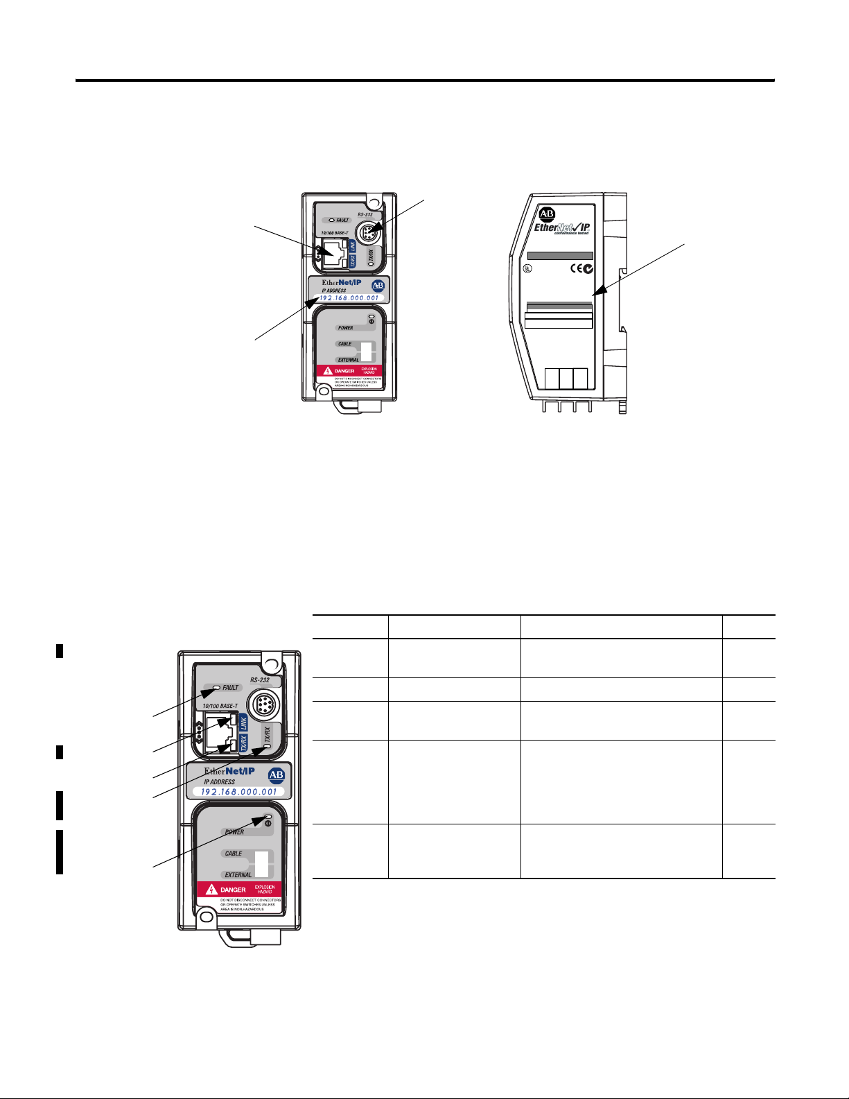
Hardware Features
Ethernet Port
Series A/B: 10-Base-T
Series C/D: 10/100-Base-T
IP Address
Write-On Area
Product Drawing
RS-232
Mini-DIN Port
ETHERNET
INTERFACE
CAT FRN
1761-NET-ENI 2.20
ENI*B22001020001 FAC. xx
LISTED IND.CONT.EQ. FOR HAZ.
LOC. A196
R
CUS
OPERATING TEMPERATURE CODE T3C
CLASS I, GROUPS A,B,C, AND D, DIV 2
ETHERNET ADDRESS
FF-FF-FF-FF-FF-FF
EXTERNAL POWER REQUIREMENTS
24 V dc +10/-15% AT 100 mA
N.E.C. CLASS 2
USE EXTERNAL DC SOURCE
FOR CLASS I DIVISION 2
APPLICATIONS. SEE
INSTALLATION INSTRUCTIONS
MADE IN U.S.A.
24VDC
NEUT
DC
SER
B
N223
GND
CHS
LED Indicators
The ENI and ENIW have five LED indicators:
Ethernet Hardware
Address
Series A/B
FAULT
LINK
Ethernet TX/RX
RS-232 TX/RX
POWER
Table 1.1 Series A/B Descriptions
LED Description Function Color
RS-232
TX/RX
RS-232 data
transmission indicator
flashes when the RS-232 port is
transmitting or receiving data
green
POWER module power lit when module is powered green
LINK Ethernet link status lit when there is a valid physical
green
Ethernet connection
Ethernet
TX/RX
Ethernet data
transmission indicator
flashes when the Ethernet port is
transmitting or receiving data
green
indicates Ethernet network traffic to
and from the ENI/ENIW
FAULT fault condition indicator lit when a fault condition is present red or
flashing
red
Publication 1761-UM006E-EN-P - August 2005
Page 15
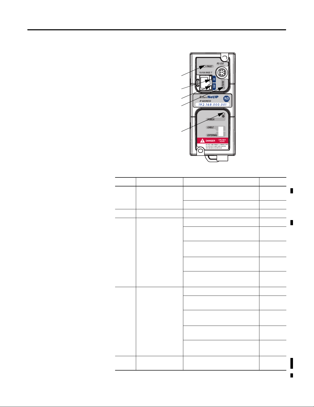
Series C
FAULT
100
RS-232 TX/RX
POWER
Table 1.2 Series C Descriptions
Product Overview 1-3
10
LED Description Function Color
RS-232
TX/RX
RS-232 data
transmission indicator
RS-232 port is transmitting or receiving
data
flashing
green
no RS-232 traffic off
POWER module power module is powered green
10 10-Base-T Ethernet
link status and data
transmission indicator
No link or continuous data activity off
10-Base-T Half Duplex; Link good
amber
however no data activity
10-Base-T Half Duplex; Link good with
sporadic data activity
(1)
10-Base- T Full Duplex; Link good
flashing
amber
green
however no data activity
10-Base-T Full Duplex; Link good with
sporadic data activity
100 100-Base-T Ethernet
link status and data
transmission indicator
No link or continuous data activity off
100-Base-T Half duplex; Link good
however no data activity
100-Base-T Half Duplex; Link good
with sporadic data activity
100-Base-T Full Duplex; Link good
(1)
(1)
flashing
green
amber
flashing
amber
green
however no data activity
100-Base-T Full Duplex; Link good with
sporadic data activity
(1)
flashing
green
FAULT fault condition
lit when a fault condition is present red or
indicator
(1) Any Ethernet network activity; not necessarily to or from the ENI/ENIW.
Publication 1761-UM006E-EN-P - August 2005
flashing red
Page 16
1-4 Product Overview
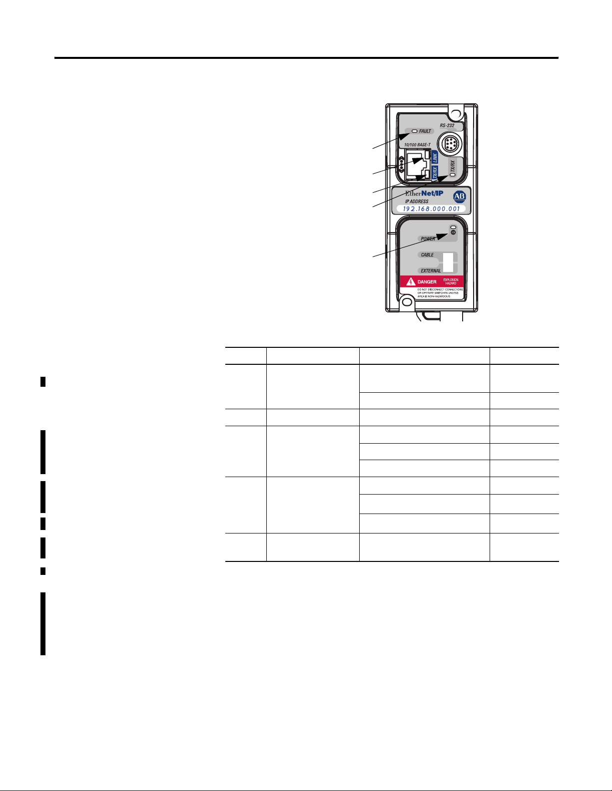
Series D
FAULT
LINK
Ethernet TX/RX
RS-232 TX/RX
POWER
Table 1.3 Series D Descriptions
LED Description Function Color
RS-232
RS-232 data
transmission indicator
RS-232 port is transmitting or
receiving data
flashing green
TX/RX
no RS-232 traffic off
POWER module power module is powered green
LINK
Ethernet link status and
10-Base-T or
100-Base-T indicator
No link off
10-Base-T link amber
100-Base-T link green
Ethernet activity status
Ethernet
TX/RX
and Half Duplex or Full
Duplex status
FAULT fault condition
indicator
(1) Any Ethernet network activity; not necessarily to or from the ENI/ENIW.
No activity off
Half Duplex activity
Full Duplex activity
(1)
(1)
lit when a fault condition is
present
flashing amber
flashing green
red or flashing
red
After out-of-box power-up, the most common reason for a flashing
red fault LED is because an IP address has not yet been assigned via
BOOTP. Either set up a BOOTP server to assign an IP address or
modify the ENI/ENIW configuration to use a specific IP address or to
obtain an IP address via a DHCP server.
Publication 1761-UM006E-EN-P - August 2005
For more detailed information on LED operation, see Chapter 9,
Troubleshooting.
Page 17

Product Overview 1-5
IMPORTANT
The IP addresses in any of the examples in this
manual were arbitrarily assigned and should only be
used on an isolated Ethernet network. Contact your
system administrator for unique IP addresses if you
are connecting your Ethernet devices to your
employer’s Ethernet network.
Default Settings
The ENI/ENIW has the following default settings:
Table 1.4 RS-232 Settings
Setting Default Other Options
Baud Rate Autobaud see table 4.2
Handshaking (hardware, software) none none
Data Bits 8 none
Stop Bits 1 none
Parity none none
Table 1.5 DF1 Settings
Setting Default Other Options
Duplicate Message Detection Enabled none
Error Detection Auto-detect (for
Autobaud)
Embedded Response Operation
DLE ACK Timeout 1 second none
DLE NAK Receive 3 NAK retries none
DLE ENQ for Response 3 ENQs retries none
DF1 Node Address Don’t Care
(1) Connected controllers should be configured for Embedded Responses Disabled or Auto-detect.
Disabled
(1)
Auto-detect when
Autobaud is true,
otherwise CRC
none
Publication 1761-UM006E-EN-P - August 2005
Page 18

1-6 Product Overview
Table 1.6 Ethernet Settings
Setting Default Other Options
Ethernet Speed/Duplex
(1)
10 Mbps half-duplex
(series A, B)
Auto Negotiate (series C, D)
0 = Auto Negotiate
1 = 10 Mbps half-duplex
2 = 10 Mbps full-duplex
3 = 100 Mbps half-duplex
4 = 100 Mbps full-duplex
SMTP Username
SMTP Password
(1)
(1)
SMTP Authentication
null 45 character username
null 45 character password
(1)
Disabled 0 = Disabled
1 = Enabled
Configuration Security
000.000.000.000 Valid IP address
Mask
Save/Reset
(2)
n/a 0 = save configuration to flash
1 = simple reset
2 = reset to out-of-box defaults
3 = reset to out-of-box, except
maintain current IP
configuration
From String ENI192.168.1.254@eni1761.
(4)
org
IP Address 000.000.000.000
(1)
(5)
Subnet Mask
192.168.1.254
0.0.0.0
ENI/ENIW Identifier
valid IP Address
valid subnet mask
Gateway Address 0.0.0.0 valid IP address
Security Mask 1 0.0.0.0 valid IP address
Security Mask 2 0.0.0.0 valid IP address
Email Server 000.000.000.000 valid IP address
BOOTP Configuration 0 0 = BOOTP initially
1 = BOOTP/DHCP disabled
(6)
(6)
(6)
Baud Rate
2 = BOOTP fallback
3 = BOOTP always
4 = DHCP always
(3)
See page 4-14. Autobaud enabled with
autodetect of CRC/BCC
Ethernet Hardware
Address
Factory Value - Read Only
(see the nameplate on the
Factory Value
unit)
(1) Series D only.
(2) See page 4-19.
(3) Changes to the Baud Rate take effect when the ENI/ENIW power is cycled, or the configuration is saved to
flash.
(4) TThe ENI/ENIW address, 192.168.1.254 will be replaced by the IP address assigned to the ENI/ENIW. For
example, the string may be ENI191.225.181.52@eni1761.org. If the ENI/ENIW does not have an assigned IP
address, the string will be read as ENI192.168.1.254@eni1761.org for the series D or ENI0.0.0.0@eni1761.org
for series A, B, or C.
(5) See page 4-17 for Subnet Mask auto-detect mode details.
(6) Series C and higher.
Publication 1761-UM006E-EN-P - August 2005
Page 19

Product Overview 1-7
Operating Modes
Device Compatibility
Messaging
When the ENI/ENIW is connected to a programmable controller (and
connected to an Ethernet network), the controller can be accessed
from other devices on Ethernet, or initiate communications to other
EtherNet/IP devices.
Email
The ENI/ENIW also support SMTP mail service, which allows a
controller to send email messages to any email address on the
network. The email can be used to initiate the transmission of data or
status information.
The ENI/ENIW are compatible with the following devices and
applications:
• All MicroLogix, SLC, PLC-5, CompactLogix, FlexLogix, and
ControlLogix controllers, which support DF1 Full-Duplex on an
available RS-232 port
• Personal Computers using the RSLinx (V2.30.00 and higher) DF1
Full-Duplex Driver
• Other DF1 Full-Duplex compliant products that have at least one
RS-232 port, for example, operator interface devices
• RSLinx (V2.31.00 and higher) Ethernet Driver
Series B Enhancements
The 1761-NET-ENI series B features the following enhancements:
• elimination of the need for two ENIs in a CompactLogix,
FlexLogix, or ControlLogix system using RSLogix 5000
• ability to use Dynamic Host Configuration Protocol (DHCP)
• two new BOOTP options
The 1761-NET-ENIW has the same features as the 1761-NET-ENI, but
includes web-serving capabilities as discussed on page 1-9.
Publication 1761-UM006E-EN-P - August 2005
Page 20

1-8 Product Overview
Series C Enhancements
Series D Enhancements
The 1761-NET-ENI/ENIW series C features the following
enhancements:
• 10/100-Base-T Ethernet port that auto-negotiates between
10 Megabits per second and 100 Megabits per second, either
half-duplex or full-duplex.
• increased temperature range up to 60°C (140°F)
• increased messaging performance
The ENI/ENIW series D features the following enhancements:
• Ability to configure the ENI/ENIW over Ethernet
• Email user authentication for open mail servers
• Ability to force 10 Mbps or 100 Mbps and half-duplex or
full-duplex Ethernet configuration
• Diagnostic web-page for Ethernet connections in use
• Revised web-page formats for ENIW
Ethernet Networks
Basic Ethernet Topology
The ENI/ENIW Ethernet connectors conform to ISO/IEC 8802-3 STD
802.3 and utilizes 10/100 Base-T media. Connections are made directly
from the ENI/ENIW to an Ethernet switch. The network setup is
simple and cost effective. Typical network topology is pictured below.
Ethernet
Switch
to PC Ethernet Card or
other Ethernet Device
RJ45 connectors on
both ends of cable
(10/100 Base-T)
to ENI or ENIW
Publication 1761-UM006E-EN-P - August 2005
Page 21

Product Overview 1-9
Web Server Functionality
IMPORTANT
The ENIW enhances operation with web server functionality, enabling
it to:
• display 40 data table values on 4 standard Data View web pages
consisting of 7 integer and 3 floating-point values on each page,
• display 10 user-configurable data description strings on each
Data View web page,
• display a diagnostic page with status and IP Address of active
Ethernet connections (series D only),
• password protect writable data files to prevent unauthorized
modification, and
• provide 10 user-configurable web page links.
The ENI/ENIW provides a 10/100 Base-T, RJ45
Ethernet connector which connects to standard
Ethernet hubs and switches via an 8-wire twisted
pair straight-through cable. To access other Ethernet
mediums, use 10/100 Base-T media converters or
Ethernet switches that can be connected together via
fiber, thin-wire, or thick-wire coaxial cables, or any
other physical media commercially available with
Ethernet switches. See page 2-6 for more cable
information.
You can access information about the ENI/ENIW via your web
browser. Simply enter it’s TCP/IP address into the address field of
your browser.
See Chapter 7 for details on using the ENIW’s web server capabilities.
Publication 1761-UM006E-EN-P - August 2005
Page 22

1-10 Product Overview
Publication 1761-UM006E-EN-P - August 2005
Page 23

Chapter
Installation and Wiring
This chapter covers installation and wiring for the ENI/ENIW. It is
divided into the following sections:
• European Communities (EC) Directive Compliance
• Safety Considerations
• Mounting
• External Power Supply Wiring
• ENI/ENIW Port Identification
• Ethernet Connections
• RS-232 Port Connections
2
European Communities (EC) Directive Compliance
This product has the CE mark. It is approved for installation within the
European Union and EEA regions. It has been designed and tested to
meet the following directives.
EMC Directive
This product is tested to meet the Council Directive 89/336/EC
Electromagnetic Compatibility (EMC) by applying the following
standards, in whole or in part, documented in a technical construction
file:
• EN 50081-2 EMC — Generic Emission Standard, Part 2 —
Industrial Environment
• EN 50082-2 EMC — Generic Immunity Standard, Part 2 —
Industrial Environment
This product is intended for use in an industrial environment.
Low Voltage Directive
This product is tested to meet Council Directive 73/23/EEC Low
Voltage, by applying the safety requirements of EN 61131-2
Programmable Controllers, Part 2 - Equipment Requirements and
1 Publication 1761-UM006E-EN-P - August 2005
Page 24
2-2 Installation and Wiring
Tests. For specific information required by EN 61131-2, see the
appropriate sections in this publication, as well as the Allen-Bradley
publication Industrial Automation Wiring and Grounding Guidelines
For Noise Immunity, publication 1770-4.1.
Open style devices must be provided with environmental and safety
protection by proper mounting in enclosures designed for specific
application conditions. See NEMA Standards publication 250 and IEC
publication 529, as applicable, for explanations of the degrees of
protection provided by different types of enclosure.
Safety Considerations
This equipment is suitable for use in Class I, Division 2, Groups A, B,
C, D, or non-hazardous locations only. The following WARNING
statement applies to use in hazardous locations.
WARNING
Explosion Hazard
• Substitution of components may impair suitability
for Class I, Division 2.
• Do not replace components or disconnect
equipment unless power has been switched off
and the area is known to be non-hazardous.
• Do not connect or disconnect connectors or
operate switches while circuit is live unless the
area is known to be non-hazardous.
• This product must be installed in an enclosure.
All cables connected to the product must remain
in the enclosure or be protected by conduit or
other means.
• The ENI/ENIW must be operated using the
external power source. The DC power source
switch must be in the EXTERNAL position.
• All wiring must comply with N.E.C. article
501-4(b).
Publication 1761-UM006E-EN-P - August 2005
Use only the following communication cables and replacement
connectors in Class I Division 2 Hazardous Locations.
Environment Classification Communication Cable and Connectors
Class I, Division 2 Hazardous
Environment
1761-CBL-PM02 Series C 2707-NC8 Series B
1761-CBL-HM02 Series C 2707-NC9 Series B
1761-CBL-AM00 Series C 2707-NC10 Series B
1761-CBL-AP00 Series C 2707-NC11 Series B
Page 25
External Power Supply Wiring
WARNING
Installation and Wiring 2-3
EXPLOSION HAZARD
In Class I Division 2 applications, an external, Class 2
power supply must be used. The DC Power Source
selector switch on the ENI/ENIW must be set to
EXTERNAL before connecting the power supply to
the ENI/ENIW.
Mounting
IMPORTANT
• In non-hazardous locations, external power is not
required. Some devices (such as a MicroLogix
24
VDC
DC
NEUT
CHS
GND
controller) provide power to the ENI/ENIW via a
cable connected to the ENI/ENIW’s port 2. Be
sure to set the DC power source selector switch
to match your particular configuration, CABLE or
EXTERNAL.
Bottom View
• Always connect the CHS GND (chassis ground)
terminal to the nearest earth ground. This
connection must be made whether or not an
external 24V dc supply is used.
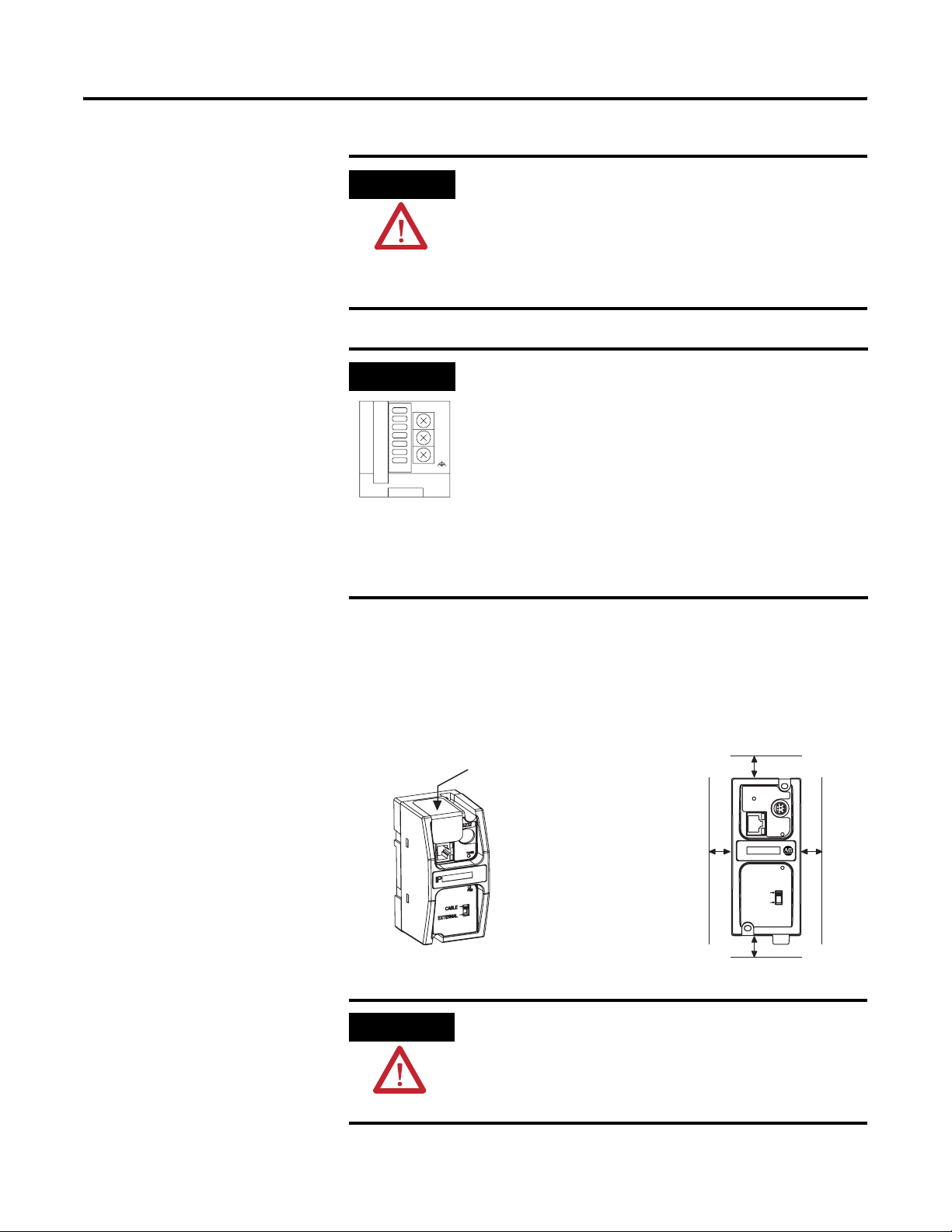
The ENI/ENIW must be mounted in the vertical position, as shown.
Horizontal mounting is not recommended due to thermal considerations. Allow 50 mm
(2 in.) of space on all sides for adequate ventilation. See page A-1 for
operating temperature specification.
protective debris strip
ETHERNET
FAULT
top
RS232
ATTENTION
TX/RX
side side
IP
CABLE
EXTERNAL
PWR
bottom
Do not remove the protective debris strip until after
all the equipment in the panel is mounted and wiring
is complete. Once wiring is complete, remove the
protective debris strip. Failure to remove strip before
operating can cause overheating.
Publication 1761-UM006E-EN-P - August 2005
Page 26
2-4 Installation and Wiring
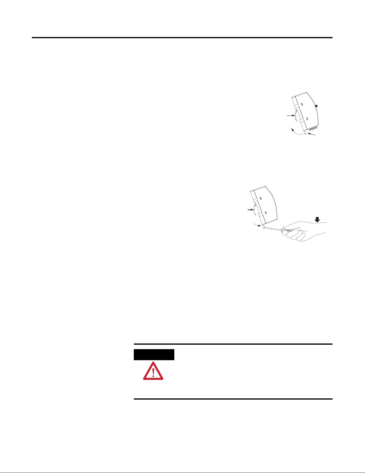
DIN Rail Mounting
Installation
1. Mount your DIN rail.
2. Snap the DIN rail latch into the closed
position.
3. Hook the top slot over the DIN rail.
4. While pressing the unit against the rail,
snap the unit into position.
Removal
1. Place a screwdriver in the
DIN rail latch at the bottom
of the unit.
DIN
Rail
2. Holding the unit, pry
downward on the latch until
the unit is released from the
DIN rail.
Panel Mounting
DIN
Rail
Latch
Side
View
Publication 1761-UM006E-EN-P - August 2005
Temp la te
See Appendix A for panel mounting dimensions.
Installation
ATTENTION
Be careful of metal chips when drilling mounting
holes for your equipment within the enclosure or
panel. Drilled fragments that fall into the equipment
could cause damage. Do not drill holes above
mounted equipment if the protective debris strip has
been removed.
Page 27
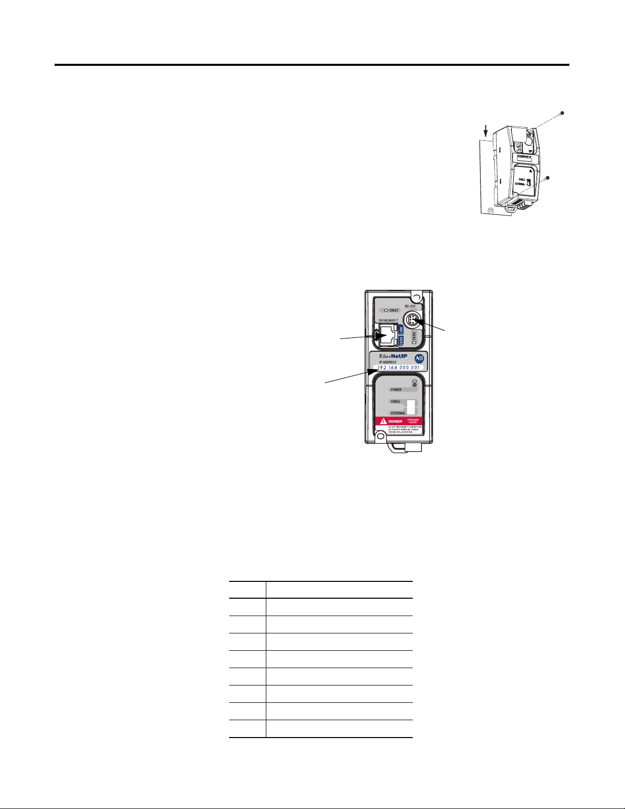
ENI/ENIW Port Identification
1. Remove the mounting template from
the back of the installation instructions.
2. Secure the template to the mounting
surface.
3. Drill holes through the template.
4. Remove the mounting template.
5. Mount the unit.
Installation and Wiring 2-5
Mounting
Tem pl at e
Ethernet Connections
Ethernet Port (Port 1)
Write-on area for
Ethernet IP address
RS-232 Mini-DIN (Port 2)
Ethernet 8-Pin 10/100-Base-T Connector (Port 1)
The Ethernet connector is an RJ45, 10/100-Base-T connector. The
pin-out for the connector is shown below:
Pin Pin Name
1Tx+
2Tx-
3Rx+
4 not used
5 not used
6Rx-
7 not used
8 not used
Publication 1761-UM006E-EN-P - August 2005
Page 28

2-6 Installation and Wiring
When to use straight-through and cross-over cables:
• ENI/ENIW Ethernet port to 10/100-Base-T Ethernet switch cables
utilize a straight-through pin-out (1-1, 2-2, 3-3, 6-6).
• Direct point-to-point 10/100-Base-T cables connecting the
ENI/ENIW Ethernet port directly to another ENI/ENIW Ethernet
port (or a computer 10/100-Base-T port) require a cross-over
pin-out (1-3, 2-6, 3-1, 6-2).
Ethernet Cables
Shielded and non-shielded twisted-pair 10/100-Base-T cables with
RJ45 connectors are supported. The maximum cable length between
an ENI/ENIW Ethernet port and a 10/100-Base-T port on an Ethernet
switch (without repeaters or fiber) is 100 meters (323 feet). However,
in an industrial application, the cable length should be kept to a
minimum.
With media converters or Ethernet switches, you can also connect to
the following media:
• fiber optic
• broadband
• thick-wire coaxial cable (10-Base-5)
• thin-wire coaxial cable (10-Base-2)
Maintain ENI and ENIW Cable Connections
The unshielded twisted pair (UTP) patch cable on a switch should be
labeled and treated as dedicated. Be careful when moving any cables,
as port identity may be effected. If you are using a switch and must
move the ENI/ENIW to a new port for any reason, power-cycle the
interface. The power cycle forces a new Address Resolution Protocol
(ARP) sequence which should immediately associate the ENI/ENIW’s
IP address with the port it is connected to.
To help prevent problems with network communications affected by
moving cables, discourage any field personnel from treating the ports
of a switch as “all the same”.
Publication 1761-UM006E-EN-P - August 2005
Page 29

Installation and Wiring 2-7
RS-232 Port Connections
RS-232 Connector
7
6
8-pin mini-DIN
Table 2.1 RS-232 Connector Pin Assignments
Pin Port 2
1 24V dc
2 ground (GND)
3 no connection
4 ENI/ENIW input data, RxD
5 no connection
6 no connection
5
4
2
8
3
1
7 ENI/ENIW output data, TxD
8 ground (GND)
RS-232 Cables
Port 2 of the ENI/ENIW is an 8-pin mini-DIN RS-232 port that provides
connection to DF1 compatible RS-232 devices. The table below
describes the RS-232 compatible cables.
ENI/ENIW Connected to: Catalog Number Use Cable
MicroLogix 1000, 1100, 1200, and
1500, Channel 0 (all series) 1761-CBL-AM00
1761-CBL-HM02
SLC 5/03, SLC 5/04, or
SLC 5/05, Channel 0
MicroLogix 1500 LRP, Channel 1
CompactLogix, FlexLogix, or
ControlLogix serial ports
1761-CBL-AP00
1761-CBL-PM02
Mini DIN to Mini DIN
45 cm (17.7 in)
2m (6.5 ft.)
Mini DIN to D-Shell
45 cm (17.7 in)
2m (6.5 ft.)
See page 2-2 for the list of cables that can be used in a hazardous
environment.
Publication 1761-UM006E-EN-P - August 2005
Page 30

2-8 Installation and Wiring
Publication 1761-UM006E-EN-P - August 2005
Page 31

Chapter
Operation
This chapter describes ENI/ENIW operation. The following
information is included:
• Operation Overview
• Allocation of Ethernet Connections
• ENI and ENIW Functional Overview
• General Ethernet Information
• RSLinx/RSWho Connectivity Example Using ENI/ENIW Interface
3
Operation Overview
Allocation of Ethernet Connections
Ethernet is the protocol used to transport TCP/IP messages. On top of
TCP, EtherNet/IP is the open protocol used by the ENI and ENIW.
EtherNet/IP allows devices to exchange information (data); or to
upload, download, and edit logic programs over Ethernet.
To communicate between devices, EtherNet/IP uses a “connection”
model. Connections are dedicated paths across Ethernet between
devices.
The ENI and ENIW support a maximum of 6 connections, allowing
simultaneous communication with up to 6 other devices or
applications. The connections are dedicated as follows:
Number of Connections Dedicated to:
2 outgoing messages
2 incoming messages
2 either incoming or outgoing messages
TIP
1 Publication 1761-UM006E-EN-P - August 2005
For peer connections, no more than one connection
per destination node is established. If multiple MSG
instructions use the same destination node, they use
the same connection.
Page 32

3-2 Operation
ENI and ENIW Functional Overview
ENI and ENIW
Function
Message Routing Node 100 to 149 Configure Route Address Integer see chapter 5
Email Node 150 to 199 Configure SMTP email address String see chapter 6
Web Data Node 200 to 204 ENIW Web page data String, integer, or
Node Group Node Function Valid Data Type For More
Node 0 to 49 Route DF1 MSG to IP at Configured Route
Node 50 to 99 Send email message to configured SMTP
The ENI and ENIW provide EtherNet/IP connectivity for RS-232
devices that use DF1 full-duplex protocol. DF1 full-duplex is an open,
point-to-point protocol used in any Allen-Bradley controller with an
RS-232 port, and in many other devices. DF1 full-duplex supports up
to 255 node addresses. The ENI and ENIW use these node addresses
for different functions.
The ENI and ENIW use a memory (node) map to provide access to
the different functions you can perform. Each function uses a different
group of node addresses. The following table illustrates the ENI and
ENIW functions by groups of node numbers:
Information
Integer see chapter 5
Address
String see chapter 6
email address
see chapter 7
floating point
ENI and ENIW
Configuration
Node 241 to 254 ENI and ENIW Configuration Registers Integer or String
General Ethernet Information
RSLinx/RSWho Connectivity Example Using ENI/ENIW Interface
see chapter 4
depending on parameter
Each Ethernet device requires a unique IP address. If your Ethernet
network is isolated from the company-wide network, any valid IP
address may be used. If your Ethernet hub is connected to a larger
Ethernet network, contact your System Administrator for unique IP
addresses.
For this example, the following IP addresses will be assigned to the
various Ethernet devices on our network:
Table 3.1 Example Network IP Addresses
IP Address ENI or ENIW Series Device
131.200.50.92 SLC 5/05 controller
131.200.50.93 1756-ENBT
131.200.50.94 Series A ENI 1761-NET-ENI #2 (1769-20 or 1769-L3x
CompactLogix controller)
131.200.50.95 Series A ENI or B/C/D
(ENI or ENIW)
1761-NET-ENI #1 (computer COMM port)
Publication 1761-UM006E-EN-P - August 2005
Page 33

Operation 3-3
Table 3.1 Example Network IP Addresses
IP Address ENI or ENIW Series Device
131.200.50.96 computer’s Ethernet card
131.200.50.97 Series B/C/D 1761-NET-ENI/1761-NET-ENIW #3
(1769-L20 or 1769-L3x CompactLogix
controller)
131.200.50.98 Series A or B/C/D 1761-NET-ENI/1761-NET-ENIW #4
(MicroLogix 1500)
The subnet mask for each Ethernet device is then, 255.255.0.0.
RS-232/DF1
ENI #2 (Series A)
24V dc
1756-Lx (ControlLogix)
IMPORTANT
The RS-232/DF1 interface between the
CompactLogix controller and its ENI/ENIW module,
and between the computer (RSLogix5000/RSLinx)
and its ENI/ENIW module, should use 38400 baud.
This will allow the fastest upload/download of
programs.
(For series A and B ENI or series B ENIW only)
When using 38400 baud, the number of Stop Bits in
RSLinx and in the CompactLogix controller must be
set to 2.
Figure 3.1 Example Ethernet Network
ETHERNET
RS232
1769-Lxx (CompactLogix)
ETHERNET
RS232
FAULT
NET
TX/RX
TX/RX
IP
PWR
CABLE
EXTERNAL
...
< > ETHERNET
FAULT
ENI #3
NET
TX/RX
TX/RX
IP
PWR
(Series B/C/D)
CABLE
EXTERNAL
24V dc
Ethernet
Hub/Switch
(10 Base T)
1769-Lxx (CompactLogix)
1747-L55x (SLC 5/05)
ENI #4 (Series A or B/C/D)
ETHERNET
RS232
FAULT
NET
TX/RX
TX/RX
IP
PWR
CABLE
EXTERNAL
PC Ethernet
Interface Card
MicroLogix 1500
Personal Computer with
RSLogix 5000, RSLogix 500
and RSLinx
1756-ENBT
24V dc
PC COMM Port
ETHERNET
RS232
FAULT
NET
TX/RX
TX/RX
IP
RS-232/DF1
PWR
CABLE
EXTERNAL
ENI #1 (only
necessary for
connection to
series A ENI #2)
Publication 1761-UM006E-EN-P - August 2005
Page 34

3-4 Operation
The ENI/ENIW allows you to connect from your PC to controllers over
Ethernet. The following procedure can be used when the computer
has a connection directly onto Ethernet (PCI card, PCMCIA interface,
built in TCP/IP port, etc.) and also when the ENI/ENIW is plugged
into the computer’s RS-232 (COMM) port.
PC Connected Directly to Ethernet (RSLinx on Ethernet)
IMPORTANT
You must use RSLinx version 2.31.00 or newer to
browse with the ENI/ENIW series B or higher via
Ethernet to a CompactLogix controller.
Follow these steps to configure RSLinx for Ethernet operation.
1. Open RSLinx and open the driver configuration dialog.
Publication 1761-UM006E-EN-P - August 2005
Page 35

Operation 3-5
2. Select “Ethernet devices” from the available drivers, and then
click “OK” to load the driver into RSLinx.
TIP
The RSLinx Ethernet/IP driver may also be
used with series B (FRN 2.31) ENIs and higher.
The advantage of this driver is that it can
‘discover’ the ENIs on a network even when
the IP addresses have not been manually
entered. The disadvantage of this driver is that
the RSWho browse displays only the ENI and
not the MicroLogix controller that is attached to
the ENI’s serial port.
Once the Ethernet driver is loaded, either highlight and select
“Configure” or simply double click on the Ethernet driver.
3. Click “OK” to accept the default driver name.
Publication 1761-UM006E-EN-P - August 2005
Page 36

3-6 Operation
At that point, the station mapping screen will appear as
illustrated here. Double click on the row below “Host Name”,
and enter the TCP/IP addresses that match the devices on your
network.
Publication 1761-UM006E-EN-P - August 2005
When you are done entering the stations, click OK to close the
station mapping window.
Page 37

Operation 3-7
4. Open the AB_ETH-1 tree on your computer. Autobrowse should
be running and any active device that you have configured
should be shown on the screen as illustrated below.
TIP
IMPORTANT
If the ENI or ENIW shows up as an “Unrecognized
Device”, you may need to install the latest ENI or
ENIW (series B or series C/D) EDS file. You can
download this file from
http://www.ab.com/networks/eds/.
You may NOT go online through the AB_ETH-1
Ethernet driver using RSLogix 5000 to the
CompactLogix controller at IP address 131.200.50.94,
because it is connected to Ethernet using a series A
ENI. You MAY go online through the AB_ETH-1
Ethernet driver using RSLogix 5000 to the
CompactLogix controller that shows up under the
ENI at IP address 131.200.50.97, because it is
connected to Ethernet using a series B/C/D ENI.
Publication 1761-UM006E-EN-P - August 2005
Page 38

3-8 Operation
ETHERNET
AUL
RS232
NET
TX/RX
TX/RX
PWR
CABLE
EXTERNAL
ETHERNET
AUL
RS232
NET
TX/RX
TX/RX
PWR
CABLE
EXTERNAL
ETHERNET
AUL
RS232
NET
TX/RX
TX/RX
PWR
CABLE
EXTERNAL
ETHERNET
AUL
RS232
NET
TX/RX
TX/RX
PWR
CABLE
EXTERNAL
PC Connected to Ethernet via the ENI or ENIW
As shown below, the ENI/ENIW can also be used to connect a
computer’s RS-232 port to EtherNet/IP and allow program upload and
download and online sessions with a maximum of four EtherNet/IP
devices. (Note: The ENI/ENIW limits the number of concurrent
outgoing connections to four).
MicroLogix 1500
DF1 Node 4
ETHERNET
RS232
FAUL
T
NET
TX/RX
TX/RX
IP
PWR
ENI ENI ENI
CABLE
EXTERNAL
CompactLogix
DF1 Node 2
ETHERNET
RS232
FAUL
T
NET
TX/RX
TX/RX
IP
PWR
CABLE
EXTERNAL
ETHERNET
RS232
FAUL
T
NET
TX/RX
TX/RX
IP
PWR
CABLE
EXTERNAL
CompactLogix
DF1 Node 3
24V dc24V dc
Ethernet
ETHERNET
RS232
FAUL
T
NET
TX/RX
TX/RX
IP
ENI Route Configuration
PWR
CABLE
EXTERNAL
TCP/IP DF1
131.200.50.92 Node 1
131.200.50.94 Node 2
131.200.50.97 Node 3
131.200.50.98 Node 4
24V dc
RSLogix/RSLinx SLC 5/05
DF1 Node 1
When using the ENI/ENIW as the computer’s interface, you can only
perform functions supported by RSLogix/RSLinx and ENI/ENIW
configuration operations (using the ENI/ENIW Configuration Utility).
In addition, before you can use the ENI/ENIW to connect across
Ethernet to destination devices in this fashion, the ENI/ENIW must
have a valid TCP/IP address, and you must configure the ENI/ENIW’s
message routing table (nodes 100 to 149). Once the ENI/ENIW is
properly configured, you can configure RSLinx.
Publication 1761-UM006E-EN-P - August 2005
Page 39

RSLinx Configuration
1. Open RSLinx.
2. Open the configure drivers dialog box.
3. Select RS-232 DF1 devices. Click Add New.
4. Configure AB_DF1-1 driver to match the example below.
Operation 3-9
5. Click OK when the AB_DF1-1 driver is configured.
TIP
The 1770-KF3/1747-KE device type only allows you
to address nodes 0 to 31 (decimal). In order to
address nodes 32 to 49, you must select the
1770-KF2/1785-KE device type and convert the octal
addresses to decimal (40
= 3210 . . . 618 = 4910).
8
Publication 1761-UM006E-EN-P - August 2005
Page 40

3-10 Operation
6. If you have set up the ENI/ENIW Message Routing table with IP
addresses in entries between 1 and 31, those devices should
respond when you browse the AB_DF1 driver.
TIP
IMPORTANT
IMPORTANT
If you use the AB_DF1 driver through an
ENI/ENIW, you may go online with
CompactLogix controllers using RSLogix 5000
whether they are connected to Ethernet through
series A or series B/C/D ENI/ENIW modules.
Although you may be able to successfully
browse a 1756-Lxx controller located in slot 0
through a 1756-ENxT module using the
AB_DF1 driver with an ENI/ENIW, you will not
be able to go online with that 1756-Lxx
controller using RSLogix 5000 programming
software. If you attempt to do so, the following
error occurs: ‘Failed to go online with the
controller. No open connection.’
You can browse a maximum of four devices at
one time from the DF1 driver, because the
ENI/ENIW supports only four outgoing
connections.
Publication 1761-UM006E-EN-P - August 2005
Page 41

Chapter
ENI/ENIW Configuration (Nodes 241 to 254)
This chapter describes configuration methods and parameters. It is
arranged as follows:
• Configuration Methods
• ENI/ENIW Configuration Utility
• Controller Messaging
• ENI/ENIW Configuration Parameters
• Configuring ENI/ENIW Data Parameters
• Configuring ENI/ENIW String Parameters
4
Configuration Methods
ENI/ENIW Configuration Utility
The ENI/ENIW’s IP information can be entered using either:
• the ENI/ENIW Configuration Utility via the RS-232 port
• the ENI/ENIW Configuration Utility via Ethernet, using Com Port
Redirector software (for series D only)
• a write message from the Allen-Bradley controller to node
address 250 via the RS-232 port
• a BOOTP server over Ethernet (BOOTP configuration is
described in Appendix B of this manual)
• a DHCP server over Ethernet (once configured for DHCP)
The ENI/ENIW Configuration Utility is free software designed for
configuring the ENI/ENIW. It is available for download from the
Downloads page of any MicroLogix controller at
www.ab.com/micrologix.
The Com Port Redirector software, which allows ENI/ENIW
configuration over Ethernet, is also available for download from
www.ab.com/micrologix.
This section provides information on how to:
• Make configuration selections using the Configuration Utility.
• Use the Configuration Utility over RS-232.
• Use the Configuration Utility over Ethernet with the Com Port
Redirector software.
1 Publication 1761-UM006E-EN-P - August 2005
Page 42

4-2 ENI/ENIW Configuration (Nodes 241 to 254)
Make Configuration Settings
COM Port Settings
Use the Utility Settings tab to set the following:
• COM Port – The PC’s RS-232 port that the communications cable
is plugged into, or the COM port that the Com Port Redirector is
configured for.
• Baud Rate – Set the baud rate to match the baud rate configured
for the ENI/ENIW. If you’re not sure which baud rate the
ENI/ENIW is configured for, try the available baud rates listed in
Table 4.2, starting with 38,400 and then 19,200. These are the
most commonly used baud rates.
• Parameter Upload Behavior and Parameter Download
Behavior – This setting controls which parameters will be saved
or loaded when you use the Load From or Save To buttons.
• Configuration Security Mask – The Configuration Security Mask
can limit which computers are allowed to configure the ENI or
ENIW over Ethernet, based on their IP Address. A Configuration
Security Mask of 000.000.000.000 or 255.255.255.255 allows any
computer to configure the ENI or ENIW over Ethernet.
Otherwise, the Configuration Security Mask acts as a filter on a
source IP address such that any mask octet set to the value of
255 becomes ‘don’t care’. Octets in the source IP and all other
fields must match exactly.
The following examples illustrate how the Configuration
Security Mask behaves:
Publication 1761-UM006E-EN-P - August 2005
If a Configuration Security Mask is set to 192.168.15.255
and an IP address of 203.129.75.23
is received, the packet is rejected because 203.129.75 does not
equal 192.168.15. The fourth octet (23) is ‘don’t care’.
If an IP Address of 192.168.15.76
is received, the packet is processed because the upper three
octets match. The fourth octet is still ‘don’t care’.
Page 43

ENI/ENIW Configuration (Nodes 241 to 254) 4-3
If a Configuration Security Mask is set to 192.168.255.76
all source IP Addresses that equal 192.168.xxx.76
will be accepted.
RS-232 Baud Rate, TCP/IP Parameters, BOOTP/DHCP, and Ethernet
Speed/Duplex Options
Use the ENI/ENIW IP Addr tab to set the following:
• ENI Series – Select A, B/C or D, depending on which series
ENI/ENIW you are configuring.
• 232 Baud Rate – Select a baud rate or choose Autobaud. See
page 4-14 for more information.
• TCP/IP Parameters – See page 4-15 for more information on
valid addresses.
(1)
• Obtain via BOOTP – At power-up, if the ENI/ENIW does not
already have a saved IP address, it transmits a BOOTP request. If
a BOOTP response is received, this IP address is saved for all
subsequent power cycles. If a BOOTP response is not received,
then the fault LED continues to flash and no further Ethernet
communication takes place (series A, B, and C). For series D
only, in this situation, Ethernet configuration can be
accomplished using the default IP address or 192.168.1.254.
• Other BOOTP/DHCP Options – See the following section on
series B and higher options and also see Table 4.3 on page 4-15
for details on the settings.
TIP
If you want to obtain the TCP/IP information
via BOOTP, you must do that separately from
the ENI/ENIW Configuration Utility. See
Appendix B.
(1) Entering leading zeros in the octets of the IP address will not convert the decimal address to a octal value.
Publication 1761-UM006E-EN-P - August 2005
Page 44

4-4 ENI/ENIW Configuration (Nodes 241 to 254)
Series B, C, and D Options
The latest 1761-NET-ENI/1761-NET-ENIW Configuration Utility
features the following options that apply to series B or later modules:
• CompactLogix Routing Checkbox – allows a Logix controller
connected to the ENI/ENIW to go online using RSLogix 5000 on
Ethernet.
• Always Checkbox – when this checkbox is selected, the
ENI/ENIW attempts to obtain the BOOTP IP address on every
power cycle. The Always option is only available when Obtain
via BOOTP has already been selected.
• Fallback Checkbox – when this checkbox is selected, the
ENI/ENIW attempts to obtain a BOOTP IP address on every
power cycle. If a response is received, the ENI/ENIW uses the
obtained address. If a response is not received, the ENI/ENIW
“falls back” to the previously assigned IP address. If an IP
address had not previously been assigned, the ENI/ENIW fault
LED continues to flash and no further Ethernet communication
takes place. The Fallback option is only available when Obtain
via BOOTP has already been selected.
• DHCP Checkbox – when this checkbox is selected, the
ENI/ENIW attempts to obtain the IP address from a DHCP server
on every power cycle. If no DHCP reply is received, then
ENI/ENIW fault LED continues to flash and no further Ethernet
communication takes place.
Series D Options
The Ethernet Speed/Duplex selection in the Configuration Utility
applies only to series D or later units. Select a forced speed and
duplex setting or select Auto Negotiate.
Save to ENI/ENIW RAM or ENI/ENIW ROM
You must save the configurations you have set. Click ENI/ENIW RAM
for temporary setups or ENI/ENIW ROM to permanently save your
settings. If you do not save the settings, they will revert to the last
saved settings (or the “out-of-box” if no settings were previously
saved).
Publication 1761-UM006E-EN-P - August 2005
Page 45

ENI/ENIW Configuration (Nodes 241 to 254) 4-5
Email Settings
Use the email screen to fill in the information for email messages.
Email servers are described on page 4-15. See Chapter 6 for
information on the “To” and “From” strings.
The Configuration Utility provides fields for a Username and Password
required for authentication to an open SMTP mail server. The SMTP
Authentication checkbox, Username, and Password apply only to
series D modules.
Message Routing
Use the Message Routing screen to fill in the destination addresses for
DF1 messaging. Message routing is described in Chapter 5.
Publication 1761-UM006E-EN-P - August 2005
Page 46

4-6 ENI/ENIW Configuration (Nodes 241 to 254)
Reset
Use the Reset screen to issue reset commands and to set the type of
behavior that will occur at reset. The reset behavior options are
described on page 4-19.
For configurations uploaded from an ENI, the reset screen also
displays information, such as the ENI/ENIW Ethernet hardware
address and ENI/ENIW firmware revision.
Publication 1761-UM006E-EN-P - August 2005
Use the Configuration Utility Over RS-232
TIP
When using the ENI/ENIW Configuration Utility, be
sure to use a 1761-CBL-PM02 series C cable
between the ENI/ENIW and the computer.
Also, make sure RSLinx is not running a driver that
is using the COM port that you plan to use for the
ENI/ENIW Configuration Utility.
Page 47

ENI/ENIW Configuration (Nodes 241 to 254) 4-7
1. Open the ENI/ENIW Configuration Utility.
2. On the Utility Settings tab, select the appropriate COM port and
baud rate.
• COM Port – The PC’s RS-232 port that the communications
cable is plugged into.
• Baud Rate – Set the baud rate to match the baud rate
configured for the ENI/ENIW. If you’re not sure which baud
rate the ENI/ENIW is configured for, try the available baud
rates listed in Table 4.2, starting with 38,400 and then 19,200.
These are the most commonly used baud rates.
3. Click the (Load From) ENI button.
The configuration is uploaded from the RS-232 com port.
The ENI/ENIW Configuration Utility may now be used for all
configuration operations over RS-232.
Publication 1761-UM006E-EN-P - August 2005
Page 48

4-8 ENI/ENIW Configuration (Nodes 241 to 254)
Use the Configuration Utility Over Ethernet (Series D only)
TIP
When using the ENI/ENIW Configuration Utility via
Ethernet, connect the ENI/ENIW to the same
subnet as the computer.
Redirect the COM port to the ENI/ENIW IP Address
1. Download the Com Port Redirector software from
www.ab.com/micrologix.
2. Install the Com Port Redirector software.
3. Open the Port Redirector configuration utility by selecting
Programs>Com Port Redirector>Configuration.
Publication 1761-UM006E-EN-P - August 2005
4. The splash screen appears briefly, followed by the configuration
screen.
5. Click on the Com Setup button.
Page 49

ENI/ENIW Configuration (Nodes 241 to 254) 4-9
6. Select the port, or ports, you want to redirect and click OK.
You may either assign each ENI/ENIW its own Com port
address, or use only one Com port and modify the IP address
that the Com port is configured for before running the
ENI/ENIW Configuration Utility.
If a Com port is grayed out, it is in use and cannot be selected.
7. Using the pull-down menu, select the port you want to redirect
to the ENI or ENIW.
8. Click the Add IP button.
Publication 1761-UM006E-EN-P - August 2005
Page 50

4-10 ENI/ENIW Configuration (Nodes 241 to 254)
9. In the Host field, enter the IP Address of the ENI or ENIW. In the
TCPPort field, enter 10001. Click OK.
TIP
If a BOOTP or DHCP server provided the IP
Address, browse using RSLinx to determine
the IP Address. Otherwise, the default
out-of-box IP Address for the series D
ENI/ENIW is 192.168.1.254.
10. The redirect IP Address and port are displayed for COM2.
11. Click the Port Settings button.
12. Select Raw Mode and click OK.
Publication 1761-UM006E-EN-P - August 2005
13. Click the save button.
Page 51

ENI/ENIW Configuration (Nodes 241 to 254) 4-11
14. The software notifies you that changes take effect when the port
is reopened. Click OK.
15. Click OK and then close the Com Port Redirector.
16. Reboot the PC, if requested.
Configure the ENI/ENIW
1. Open the ENI/ENIW Configuration Utility.
2. On the Utility Settings tab, select the appropriate COM port.
3. Select the ENI IP Addr tab. Click the (Load From) ENI button to
upload over Ethernet through the redirected com port.
The ENI/ENIW Configuration Utility may now be used for all
configuration operations over Ethernet using the Com Port Redirector.
The Redirector will automatically operate each time the configured
COM port is accessed.
Publication 1761-UM006E-EN-P - August 2005
Page 52

4-12 ENI/ENIW Configuration (Nodes 241 to 254)
Controller Messaging
When using this method, a write message is used to configure the
TCP/IP configuration parameters. A 485CIF write message is initiated
to the controller. CIF stands for Common Interface File and is
supported by all Allen-Bradley programmable controllers that have an
RS-232 port.
TIP
A 485CIF write may also be referred to as a PLC2
Unprotected Write.
The first item to configure is the ENI/ENIW’s IP address on your
network. See the following section, Configuring ENI/ENIW Data
Parameters, for that configuration procedure.
IMPORTANT
The IP addresses in any of the examples in this
manual were arbitrarily assigned and should only be
used on an isolated Ethernet network. Contact your
system administrator for unique IP addresses if you
are connecting your Ethernet devices to your
employer’s Ethernet network.
The configuration parameters are described in more detail beginning
on page 4-12.
ENI/ENIW Configuration
The following table shows the functions that nodes 241 to 255
perform and their default values. Descriptions of each function can be
Parameters
Table 4.1 Configuration Node Functions
Node Function Data Type Number of
255 Reserved
254 Ethernet Hardware
Address
253
252 BOOTP Configuration Integer 1 0 = BOOTP initially
251 Email Server Integers 4 Valid IP Address 000.000.000.000
Baud Rate
(1)
found following the table.
Options Default
Elements
ASCII String 1 Factory Value Factory Value - Read Only
(see nameplate on unit)
Integer 1 See page 4-14. Autobaud enabled with autodetect
of CRC/BCC
0
1 = BOOTP/DHCP disabled
2 = BOOTP fallback
3 = BOOTP always
4 = DHCP always
(2)
(2)
(2)
Publication 1761-UM006E-EN-P - August 2005
Page 53

Table 4.1 Configuration Node Functions
ENI/ENIW Configuration (Nodes 241 to 254) 4-13
Node Function Data Type Number of
Options Default
Elements
250 TCP/IP Configuration Integers 4, 8, 12, 16,
Valid IP Address 000.000.000.000
or 20
249 From String ASCII String 1 ENI/ENIW Identifier
248
Save/Reset
(4)
Integer 1 0 = save configuration to flash
1 = simple reset
2 = reset to out-of-box
defaults
3 = reset to out-of-box, except
maintain current IP
configuration
245 Configuration Security
(5)
Mask
244
SMTP Authentication
Integers 4 Valid IP Address 000.000.000.000
(5)
Integer 1 0 = Disabled
1 = Enabled
243
242
241
SMTP Password
SMTP Username
Ethernet Speed/Duplex
(5)
(5)
ASCII String 1 64 character password null
ASCII String 1 64 character username null
(5)
Integer 1 0 = Auto Negotiate
1 = 10 Mbps half-duplex
2 = 10 Mbps full-duplex
3 = 100 Mbps half-duplex
4 = 100 Mbps full-duplex
192.168.1.254
(5)
ENI192.168.1.254@eni1761.org
n/a
Disabled
10 Mbps half-duplex (series A, B)
Auto Negotiate (series C, D)
(3)
(1) Changes to the Baud Rate take effect when the ENI/ENIW power is cycled, or the configuration is saved to flash.
(2) Series C and higher.
(3) The ENI/ENIW address, 192.168.1.254 will be replaced by the IP address assigned to the ENI/ENIW. For example, the string may be ENI191.225.181.52@eni1761.org. If
the ENI/ENIW does not have an assigned IP address, the string will be read as ENI192.168.1.254@eni1761.org for the series D or ENI0.0.0.0@eni1761.org for series A, B,
or C.
(4) See page 4-19 for more information on Save/Reset.
(5) Series D only.
These parameters are described in more detail in the following
sections.
ETHERNET
INTERFACE
CAT FRN
1761-NET-ENI 2.20
ENI*B22001020001 FAC. xx
LISTED IND.CONT.EQ. FOR HAZ.
LOC. A196
R
CUS
OPERATING TEMPERATURE CODE T3C
CLASS I, GROUPS A,B,C, AND D, DIV 2
ETHERNET ADDRESS
FF-FF-FF-FF-FF-FF
EXTERNAL POWER REQUIREMENTS
24 V dc +10/-15% AT 100 mA
N.E.C. CLASS 2
USE EXTERNAL DC SOURCE
FOR CLASS I DIVISION 2
APPLICATIONS. SEE
INSTALLATION INSTRUCTIONS
MADE IN U.S.A.
24VDC
NEUT
DC
SER
B
N223
GND
CHS
Hardware
Address
Node 254 - Ethernet Hardware Address
You will find the hardware address on a label affixed to the ENI/ENIW
as shown to the left. The hardware address can also be read from
node address 254.
Publication 1761-UM006E-EN-P - August 2005
Page 54

4-14 ENI/ENIW Configuration (Nodes 241 to 254)
Node 253 - Baud Rate
The first time the ENI/ENIW is powered-up (out-of-the-box), it is set
to Autobaud so that it can synchronize to the attached controller. The
baud rate can be changed by sending a message to address 253 with
one of the configuration values shown in the table below. Changes to
the baud rate take effect when the ENI/ENIW power is cycled or
when a Save configuration to flash command (write to node 248) is
received. The ENI/ENIW also performs a CRC/BCC check when
autobaud is operational.
When Autobaud is selected in an ENI/ENIW series B or higher, the
ENI/ENIW communicates with the DF1 device attached to it at each
power up to determine whether or not the ENI/ENIW should be in
‘CompactLogix Routing’ mode, and to set the baud rate and
checksum.
Table 4.2 ENI/ENIW Baud Rate Options
Baud Rate Configuration Value
For CRC with CompactLogix
Routing Disabled
(Series A and higher)
Autobaud 0 100
1200 1 101
2400 2 102
4800 3 103
9600 4 104
19.2K 5 105
(1)
38.4K
(2)
57.6K
Autobaud
Enabled
(1) All CompactLogix devices must be configured to use two stop bits when communicating with the ENI/ENIW
series A and B at 38.4K.
(2) 38.4K is the maximum serial port speed for Allen-Bradley controllers. The 57.6K setting may only be used with
RSLinx.
6 106
7 107
Autodetect of CRC/BCC occurs when autobaud is selected using values 8
to 99 and 108 to 65535.
For CRC with CompactLogix
Routing Enabled
(Series B and higher)
Publication 1761-UM006E-EN-P - August 2005
IMPORTANT
If the controller’s baud rate is from 1200 to 38.4K,
and the ENI/ENIW is configured for Autobaud, the
ENI/ENIW will synchronize with the controller’s
baud rate. The ENI/ENIW cannot Autobaud to 57.6K
to synchronize to the attached controller. You must
manually set the baud rate to 57.6K.
Page 55

Table 4.3 BOOTP Configuration Settings
ENI/ENIW Configuration (Nodes 241 to 254) 4-15
Node 252 - BOOTP Configuration
The ENI/ENIW allows the BOOTP request to be disabled by clearing
the BOOTP Enable parameter in the channel Configuration File.
BOOTP Enable behaves as follows:
Node
252
Setting
0 Obtain via BOOTP and
1 Nothing checked IP address must be configured via the Configuration Utility or via a write to node 250. A, B, C, D
2 Obtain via BOOTP and
3 Always obtain via BOOTP traditional BOOTP where ENI/ENIW does not save the result in NVRAM and relies on
4 DHCP traditional Dynamic Host Configuration Protocol (DHCP) where the ENI/ENIW does
ENI Configuration
Utility Setting
save
Fallback
Description ENI/
ENIW
Series
initial BOOTP configuration, where ENI/ENIW saves the result in non-volatile RAM
(NVRAM) and uses that saved configuration on subsequent power cycles
special BOOTP where ENI/ENIW saves the result in non-volatile RAM (NVRAM), but
tries BOOTP first. BOOTP is used only to change the IP address of the ENI/ENIW.
the BOOTP response for every power cycle
not save the result in NVRAM and relies on a DHCP response for every boot
A, B, C, D
B, C, D
B, C, D
B, C, D
When BOOTP Enable is disabled, the ENI/ENIW will wait for a
manual configuration.
The BOOTP enable/disable setting is only evaluated on power-up.
Changes to the BOOTP configuration will not take effect until the next
power cycle.
IMPORTANT
If BOOTP/DHCP is disabled, or no BOOTP/DHCP
server exists on the network, you must use a soft
configuration method to enter or change the IP
address for each ENI/ENIW. See page 4-1 for more
information.
Node 251 - Email Server
The TCP/IP address stored in this location defines the mail server. The
ENI/ENIW sends all email requests to this server, which then sends
the email message to the destination.
Node 250 - TCP/IP Configuration
This procedure describes configuration for the TCP/IP parameters.
The TCP/IP parameters are configured by sending a message
Publication 1761-UM006E-EN-P - August 2005
Page 56

4-16 ENI/ENIW Configuration (Nodes 241 to 254)
instruction to the ENI/ENIW (or by using the ENI/ENIW Configuration
Utility).
1. Configure a 485CIF/PLC2 write message in the Allen-Bradley
controller.
IMPORTANT
To configure TCP/IP parameters in this manner,
BOOTP and DHCP must be disabled.
Only PLC2 type or 485CIF write messages can
be used to configure the ENI/ENIW, node 250.
2. Set the destination (target) node to 250. Using node address 250
directs this message to the TCP/IP configuration function.
3. The local integer file must be set up for at least 4 integer
locations. The first 4 words define the IP address and are
required. All remaining variables are optional.
The table below describes the TCP/IP functions that can be
configured. The sections following the table describe the functions in
more detail.
Table 4.4 TCP/IP Configuration Parameters
Function
IP Address Integer 4 words Format aaa.bbb.ccc.ddd (decimal). The
(1)
Data
Ty pe
Length Notes
ENI/ENIW verifies the first/highest octet of any
IP as follows:
Publication 1761-UM006E-EN-P - August 2005
• The first octet is between 1 and 223 and
not equal to 127.
• The first two octets are not equal to
169.254 or 169.255.
• The first octet is 0, and the entire IP is
0.0.0.0.
Otherwise the IP address is treated as an error.
For example, 0.168.0.75 is an error, or 127.0.0.0
is an error.
Subnet Mask Integer 4 words If not sent, the default mask is derived from the
class of the IP address as shown in Table 4.5.
Gateway Integer 4 words Only needed if a Gateway is present on the
Subnet. The default is 000.000.000.000.
Security Mask 1 Integer 8 words If not present, the default is no security mask
Security Mask 2
(1) The IP address must be configured. All other functions are optional.
000.000.000.000.
Page 57

ENI/ENIW Configuration (Nodes 241 to 254) 4-17
Subnet Mask
A subnet mask is used to interpret IP addresses when the network is
divided into subnets. If your network is not divided into subnets, then
leave the subnet mask at the default or allow the ENI/ENIW
Configuration Utility to assign a default.
The subnet mask defaults to auto-detect mode ‘out-of-box’. As long as
the subnet mask is not manually set, the auto-detect mode follows the
rules as shown below:
Table 4.5 Subnet Mask Auto-Detect Operation
When the IP Address is set to: And the Subnet Mask is in auto-detect:
The Subnet Mask is set to:
Out of Box: 0.0.0.0
Class A address (First octet is 1 to 126) 255.0.0.0
Class B address (First octet is 128 to 191) 255.255.0.0
Class C address (First octet is 192 to 223) 255.255.255.0
(1) 192.168.1.254 for series D.
(1)
Switch-on auto-detect
Subnet Mask Auto-Detect Rules:
• Reading the subnet mask when the IP address is 0.0.0.0 returns a
value of 0.0.0.0.
• When you manually configure the subnet mask, auto-detect is
switched off and the configured mask is used.
• The ENI/ENIW validates the configured subnet mask and if:
– The first octet is not equal to 255, the ENI/ENIW returns
status 0x10 and reverts to the previous mask, or
– The first octet is 255, but the remaining mask is not proper,
the ENI/ENIW returns status 0x10 and reverts to the previous
mask.
• The definition of “proper” is that the mask must be a contiguous
series of 1’s with no zeroes in between (i.e. 255.0.0.0 or
255.224.0.0 or 255.192.0.0 are valid, but 255.160.0.0 is not).
Security Mask
The Security Mask, when configured, allows you to restrict controller
access to sources with IP addresses that are within some prescribed
range. For example, if you wanted to restrict all message sources to be
from within a company’s allocated IP address range, a Security Mask
could be configured that would block any IP address outside that
range. This only applies to messages to the controller. Web page
access, for example, is not restricted.
Publication 1761-UM006E-EN-P - August 2005
Page 58

4-18 ENI/ENIW Configuration (Nodes 241 to 254)
The security masks default value is 0.0.0.0 out-of-box, which is
defined as “accept all register session requests”. A Security Mask of
255.255.255.255 is also defined as “accept all register session
requests”.
TIP
The security mask acts as a filter on the source IP
address such that any mask octet set to the value of
255 becomes “don’t care” octets in the source IP
address and all other fields must match exactly.
The follow examples illustrate the behavior of the security masks:
Table 4.6 Security Mask Behavior
Example Condition Security Mask Behavior
If a security mask is set to
192.168.15.255
If a security mask is set to 192.168.255.76 All source IPs that equal 192.168.xxx.76 are accepted
and an IP address 203.129.75. 23 attempts
to message into the controller
and an IP address 192.168.15.76 attempts to
message into the controller
The packet is rejected because 203.129.75 does not equal
192.168.15 (the 4
The packet is processed because the upper 3 octets match
th
(the 4
octet is still “don’t care”).
because 255 is “don’t care”.
th
octet, 23, is “don’t care”).
You can use one or two security masks. If you wish to use only one
security mask, use Security Mask 1 because it takes precedence over
Security Mask 2 (for example, if Security Mask 1 is accepted, Security
Mask 2 is not evaluated). Details of the relationship between the two
masks are shown in the following table.
Table 4.7 Using Security Mask 1 and Security Mask 2
Example Condition Security Mask Behavior
Security masks 1 and 2 are evaluated using the following logic:
If the security mask 1 filter results in an
“Accept” decision
If the security mask 1 filter results in a
“Deny” decision
Publication 1761-UM006E-EN-P - August 2005
security mask 2 is not evaluated and the register session request is processed.
security mask 2 is evaluated as follows:
• If the security mask 2 filter results in an “Accept” decision, the register session
request is processed
• If the security mask 2 filter results in a “Deny” decision, the register session
request is not replied to and the socket is closed.
Page 59

ENI/ENIW Configuration (Nodes 241 to 254) 4-19
Node 249 - From String
Node 249 holds the ASCII string that is sent with any email message
initiated by the ENI/ENIW. Criteria for a valid email From String
include:
• The From String remains at the default value unless changed by
the user. See page 4-12 for default information.
• The From String must contain an “@” symbol.
• The From String cannot contain any spaces or special ASCII
characters.
• The maximum length of the From String is 64 characters. Any
additional characters are ignored.
• To configure the From String, initiate a message with a string
element as the data. The message instruction procedure is
shown on page 4-24.
Node 248 - Save/Reset Function
Depending on the value of the Save/Reset option, the ENI/ENIW
performs the following operations when receiving a 485CIF/PLC2
Unprotected Write message of one element (integer) to Node 248.
Table 4.8 Save/Reset Function
Value of
Save/Reset
0 The ENI/ENIW immediately stops all normal operations and saves the
1 The ENI/ENIW immediately stops all normal operations and performs a
2 The ENI/ENIW immediately stops all normal operations, performs a soft
3 The ENI/ENIW immediately stops all normal operations, performs a soft
ENI/ENIW Operation
configuration to non-volatile memory.
IMPORTANT
soft reset.
reset, and returns all parameters to their “out-of-box” settings.
reset, and returns all parameters to their “out-of-box” settings (except
for the IP address, Subnet Mask, Gateway ID, and Security Mask).
The ENI/ENIW may take up to 60 seconds to
complete this save operation. The configuration is
not permanently saved until the Save command is
sent.
Publication 1761-UM006E-EN-P - August 2005
Page 60

4-20 ENI/ENIW Configuration (Nodes 241 to 254)
Node 245 - Configuration Security Mask
The Configuration Security Mask can limit which computers are
allowed to configure the ENI or ENIW over Ethernet, based on their IP
Address. A Configuration Security Mask of 000.000.000.000 or
255.255.255.255 allows any computer to configure the ENI or ENIW
over Ethernet. Otherwise, the Configuration Security Mask allows user
to select an IP Address, or range of IP Addresses that may be used for
configuration over Ethernet. The mask is configured as follows:
If a Configuration Security Mask is set to 192.168.15.255
and an IP address of 203.129.75.23
is received, the packet is rejected because 203.129.75 does not
equal 192.168.15. The fourth octet (23) is ‘don’t care’.
If an IP Address of 192.168.15.76
is received, the packet is processed because the upper three
octets match. The fourth octet is still ‘don’t care’.
If a Configuration Security Mask is set to 192.168.255.76
all source IP Addresses that equal 192.168.xxx.76
will be accepted.
This procedure describes the application of the Configuration Security
Mask. The Configuration Security Mask is configured by sending a
message instruction to the ENI/ENIW, or by using the ENI/ENIW
Configuration Utility.
1. Configure a 485CIF/PLC2 write message in the Allen-Bradley
controller.
2. Set the destination (target) node to 245. Using node address 245
directs this message to the Configuration Security Mask function.
3. The local integer file must be set up for 4 integer locations.
Node 244 - SMTP Email Authentication Checkbox (Series D Only)
Many open mail servers now require user authentication for email.
Node 244 allows you to enable or disable the email authentication
feature (series D units only).
Publication 1761-UM006E-EN-P - August 2005
Page 61

ENI/ENIW Configuration (Nodes 241 to 254) 4-21
The ENI/ENIW performs the following Email Authentication
configuration operations when receiving a 485CIF/PLC2 Unprotected
Write message of one element (integer) to Node 244.
• 0 = Disabled
• 1 = Enabled
Node 243 - SMTP Email Authentication Password (Series D Only)
Many open mail servers now require user authentication for email.
Node 243 allows a 45 character Password to be defined for email
service (series D units only). Criteria for the Password includes:
• SMTP Email Authentication must be enabled. See Node 244 on
page 4-20.
• The Password remains at the default value unless changed by
the user. See page 4-12 for the Password default values.
• The Password cannot contain any spaces or special ASCII
characters.
• The maximum length of the Password is 45 characters. Any
additional characters are ignored.
• To configure the Password, initiate a message with a string
element as the data. See the message instruction procedure on
page 4-25.
Node 242 - SMTP Email Authentication Username (Series D Only)
Many open mail servers now require user authentication for email.
Node 242 allows a 45 character username to be defined for email
service (series D units only). Criteria for Username includes:
• SMTP Email Authentication must be enabled. See Node 244 on
page 4-20.
• The Username remains at the default value unless changed by
the user. See page 4-12 for the Username default.
• The Username cannot contain any spaces or special ASCII
characters.
• The maximum length of the Username is 45 characters. Any
additional characters are ignored.
• To configure the Username, initiate a message with a string
element as the data. See the message instruction procedure on
page 4-25.
Publication 1761-UM006E-EN-P - August 2005
Page 62

4-22 ENI/ENIW Configuration (Nodes 241 to 254)
Node 241 - Ethernet Speed and Duplex Setting (Series D Only)
This node allows speed and duplex settings of 10 Mbps or 100 Mbps
and half-duplex or full-duplex to be forced. Auto negotiation may also
be selected with this node.
The ENI/ENIW performs the following Ethernet speed/duplex
configuration operations when receiving a 485CIF/PLC2 Unprotected
Write message of one element (integer) to Node 241.
• 0 = Auto Negotiate
• 1 = 10 Mbps half-duplex
• 2 = 10 Mbps full-duplex
• 3 = 100 Mbps half-duplex
• 4 = 100 Mbps full-duplex
Configuring ENI/ENIW Data Parameters
This example illustrates how to configure the ENI/ENIW’s TCP/IP
address (Node 250).
TIP
1. Create an integer data file. Inside the file arrange your TCP/IP
data in groups of 4 words (as illustrated in file N50 below).
This procedure can also be used for any parameter
that requires integer numbers (nodes 50 to 150, 241,
244, 245, 250, 251, 252 and 253).
Publication 1761-UM006E-EN-P - August 2005
Page 63

ENI/ENIW Configuration (Nodes 241 to 254) 4-23
2. Create your message logic using whatever conditional
instructions you may need. In this MicroLogix example, bit
B3:0/8 is used to condition the message instruction and message
file 10, element 1 is used to manage the message session.
3. Open the message instruction and enter the appropriate
variables. The variables are described in Table 4.9.
Table 4.9 Message Instruction Variables for Configuring ENI/ENIW Data
Parameters
Variable Setting
This Controller Parameters:
Communication
Command
Data Table Address In this example we are using integer file 50, element 5
Size in Elements For all ENI/ENIW TCP/IP data configuration, always set this to
Channel The RS-232 communication channel that is connected to the
Target Device Parameters:
Message Timeout Leave this value at the default.
Data Table Offset Always 0.
Local Node Addr (dec). This is the destination node address, in this example it is 101.
Local/Remote Always Local.
For the ENI/ENIW configuration, this must be set to:
• 485CIF for MicroLogix and SLC
• a PLC2 Unprotected Write command for CompactLogix
and PLC-5
(instruction starts at N50:5) to set the ENI/ENIW’s IP address to
195.100.100.1.
4 (4 words).
ENI/ENIW, typically 0 or 1.
Publication 1761-UM006E-EN-P - August 2005
Page 64

4-24 ENI/ENIW Configuration (Nodes 241 to 254)
4. With the controller in Run, initiate the message. The new TCP/IP
information is transmitted to the ENI/ENIW.
Configuring ENI/ENIW String Parameters
ATTENTION
At this point, the new configuration has NOT
been saved to permanent memory. See Node
248 information on page 4-19 for instructions.
Configuring the ENI/ENIW Email From String
This example illustrates configuring the ENI/ENIW Email From String
(Node 249). To configure the Email From String, initiate a message
with a String element as the data.
IMPORTANT
Email messages can only be initiated by controllers
that support String elements. Therefore, this
functionality cannot be used with the MicroLogix
1000 family of controllers.
EXAMPLE
TIP
Node 249 - Email From String
Node 249 holds the ASCII string that will be sent
with any email message initiated by the ENI/ENIW.
To configure the Email From String, initiate a
message with a string element as the data. To do this,
follow the procedure below.
This procedure can also be used for any parameter
that requires string data (nodes 150 to 199, 242, 243,
and 249).
Publication 1761-UM006E-EN-P - August 2005
Page 65

ENI/ENIW Configuration (Nodes 241 to 254) 4-25
1. Create a valid string file element as illustrated below. This
example has data file 25 configured for string elements. In File
ST25, element 0 has a valid email from string,
Station_0@My_Company.com.
2. Create your message logic using whatever conditional
instructions you may need. This example uses bit B3:0/7 to
condition the MSG instruction and message file 10, element 16
to manage the message session.
3. Open the message instruction and enter the appropriate
variables. The variables are described in Table 4.10.
Publication 1761-UM006E-EN-P - August 2005
Page 66

4-26 ENI/ENIW Configuration (Nodes 241 to 254)
Table 4.10 Message Instruction Variables for Configuring ENI/ENIW String
Parameters
Variable Setting
This Controller Parameters:
Communication Command For the ENI/ENIW configuration, this must be set to:
• 485CIF for MicroLogix and SLC
• a PLC2 Unprotected Write command for CompactLogix
and PLC-5
Data Table Address In this example we are using string file 25, element 0 (ST25:0)
Size in Elements For all ENI/ENIW parameters that require a string
configuration, always set this to 1.
Channel The RS-232 communication channel that is connected to the
ENI/ENIW, typically 0 or 1.
Target Device Parameters:
Message Timeout Leave this value at the default.
Data Table Offset Always 0.
Local Node Addr (dec). This is the destination node address, in this example it is 249.
Local/Remote Always Local.
Publication 1761-UM006E-EN-P - August 2005
Page 67

Chapter
Peer-to-Peer Messaging
This chapter describes messaging between the ENI/ENIW and DF1
devices. The following topics are covered:
• Messaging Between the ENI/ENIW and DF1 Devices
• Message to Configuration Nodes (Nodes 100 to 149) and
Sending a Message to a Destination Controller (Nodes 0 to 49)
5
Messaging Between the ENI/ENIW and DF1 Devices
The ENI/ENIW can route a DF1 message received from the attached
controller to a compatible destination TCP/IP device, using DF1 node
addresses 0 through 49. ENI/ENIW Node addresses 100 through 149
store TCP/IP destination addresses. When the ENI/ENIW receives a
write message to nodes 100 to 149, it stores the TCP/IP destination
address in the corresponding map register.
To configure the destination TCP/IP addresses, you can use either the
ENI/ENIW Configuration Utility, or you can send a 485CIF/PLC2
message to each node as described in this section.
The table below illustrates the relationship between messages and
their corresponding configuration addresses.
Table 5.1 Message Routing
ENI/ENIW receives read
or write 485CIF/PLC2
message to
Node 0 Node100 111.222.233.200 (stored at Node 100)
Node 1 Node101 111.222.233.201 (stored at Node 101)
ENI/ENIW
TCP/IP route
configuration
Message forwarded to destination
node TCP/IP address
1 Publication 1761-UM006E-EN-P - August 2005
Page 68

5-2 Peer-to-Peer Messaging
IMPORTANT
If the ENI/ENIW receives a 485CIF/PLC2 read message to any of its
configuration addresses (nodes 100 to 149), the ENI/ENIW responds
with the current configuration of that node/address.
Using the configuration shown in Table 5.1; if the controller initiates a
read or write message to node 0, the ENI/ENIW forwards the request
to the TCP/IP address at Node 100 (111.222.233.200).
When the ENI/ENIW receives a 485CIF/PLC2 write
message to a configuration node address (100
through 149), it closes any open communications
currently active on that connection and reconfigures
the IP address to match the new configuration.
If the received data matches the current
configuration, the ENI/ENIW closes any open
communications with the destination device.
You must wait at least one second before sending a
new message to that node address or you may
receive a connection error.
Message to Configuration Nodes (Nodes 100 to 149) and Sending a Message to a Destination Controller (Nodes 0 to 49)
When the ENI/ENIW receives a message from the attached controller
to Node Address 0 to 49, it looks up the TCP/IP address associated
with the address at Nodes 100 to 149. The ENI/ENIW preserves the
original DF1 address when sending back a reply.
The following table illustrates the relationship between configuration
addresses and their corresponding messaging address.
Table 5.2 Peer-to-Peer Message Routing
Node
Number
0 DF1 Route 0 MSG 100 Route 0 IP Address Integer (4 words)
1 DF1 Route 1 MSG 101 Route 1 IP Address Integer (4 words)
2 DF1 Route 2 MSG 102 Route 2 IP Address Integer (4 words)
3 DF1 Route 3 MSG 103 Route 3 IP Address Integer (4 words)
↓↓ ↓↓ ↓
49 DF1 Route 49 MSG 149 Route 149 IP Address Integer (4 words)
(1) See the IMPORTANT note below about assigning Nodes to various devices.
Function Node
(1)
Routing Table Data Type
Number
Publication 1761-UM006E-EN-P - August 2005
Page 69

Peer-to-Peer Messaging 5-3
IMPORTANT
In the ENI/ENIW, node addresses 45 through 49 are
dedicated for sending messages to any Logix
controllers with integral Ethernet ports. In addition,
when sending messages to a ControlLogix controller
via a 1756-ENBT, the controller MUST be in slot 0 of
the ControlLogix chassis for the message to be
delivered to it.
Node addresses 0 through 44 are to be used for all
other Ethernet devices, such as other MicroLogix
controllers connected to ENI/ENIW modules or other
controllers with integral Ethernet ports, such as SLC
5/05, PLC-5E, and MicroLogix 1100.
To configure the route address (nodes 100 to 149), write a
485CIF/PLC2 message with 4 integer data words. An example is
shown in the next section of this chapter.
The procedure to send configuration data (nodes 100 to 149), or data
(nodes 0 to 49) is exactly the same as discussed previously in
‘Configuring ENI/ENIW Data Parameters’ on page 4-22.
Open the message instruction and enter the appropriate variables. The
variables are described in Table 5.3 on page 5-4.
Publication 1761-UM006E-EN-P - August 2005
Page 70

5-4 Peer-to-Peer Messaging
Table 5.3 Message Instruction Variables for Sending a Message to a Destination
Controller
Variable Setting
This Controller Parameters:
Communication Command Use any command supported by your controller and the
target device.
Data Table Address Use any valid file.
Size in Elements Use any valid size.
Channel The RS-232 communication channel that is connected to the
ENI/ENIW, typically 0 or 1.
Target Device Parameters:
Message Timeout Leave this value at the default.
Data Table Address Use any valid file.
Local Node Addr (dec). The destination node address, Nodes 0 to 49 (decimal).
Local/Remote Always Local.
Publication 1761-UM006E-EN-P - August 2005
Page 71

Chapter
EMail Messages (Node 50 to 99)
This chapter describes using the ENI/ENIW’s email feature. The
following topics are included:
• Overview
• Configuring Email
• Sending an Email Message
6
Overview
The ENI/ENIW is capable of transmitting email messages generated by
the attached controller. This provides an extremely versatile
mechanism to report alarms, status, and other data-related functions.
To send an email message, the controller generates a 485CIF/PLC2
write message, with a string element as the data, to a node number
that correlates to the email destination address.
IMPORTANT
Email messages can only be initiated by controllers
that support String elements. Therefore, this
functionality cannot be used with the
MicroLogix 1000 family of controllers.
ENI/ENIW email behavior in a system is described by the following
diagram.
Controller
485CIF/PLC2
Message with
Embedded Email
DF1 String
Message
ENI/ENIW
Mail
Queue
SMTP
Client
TCP Connection
Destination
Server
Destination
Mailbox
1 Publication 1761-UM006E-EN-P - August 2005
Local Ethernet or Internet
Primary
Relay Agent
mailgate.xyz.com
Page 72

6-2 EMail Messages (Node 50 to 99)
Configuring Email
SMTP Email Address
To configure the email function, at least two parameters must be
configured:
• SMTP Mail Server IP address - configured by sending a write
message to node 251 (email server). See page 4-15 for more
information.
IMPORTANT
• A “From” String - configure by sending a write message to
node 249 (from string). The string element text can be stored in
a String File as shown below. The string element text (ASCII
characters) contains the verbatim “from” string. See page 4-24
for more information.
The ENI/ENIW only accepts the configuration
in the form of 4 elements (words) from an
Integer file.
Publication 1761-UM006E-EN-P - August 2005
For series D ENI/ENIW only:
• SMTP Authentication -- can be enabled or disabled by sending a
write message to node 244. See page 4-20 for more information.
• SMTP Username -- if SMTP Authentication in enabled, Username
can be configured by sending a write message to node 242. See
page 4-21 for more information.
• SMTP Password -- if SMTP Authentication in enabled, Password
can be configured by sending a write message to node 243. See
page 4-21.
Page 73

EMail Messages (Node 50 to 99) 6-3
Destination Addresses
The ENI/ENIW stores email addresses; it does not store the email
messages. To store a destination address, write a message to a specific
node number (nodes 150 to 199). The message data must be a string
element that contains a valid email ASCII text string address, as
illustrated in ST15:2 through ST15:5 in the example below.
IMPORTANT
Remember the following when setting up destination
addresses:
• The ENI/ENIW can store up to 50 email
addresses.
• Email addresses can be up to 45 characters long;
exceeding this will result in an error.
• The email address must contain an “@” character.
• Email addresses cannot contain any spaces or any
other special ASCII characters other than the “@”
character.
Message Text
To send the actual email message, the controller generates a write
message, with a string element as the data (see ST15:7 to ST15:9 in the
example above) to a node number (50 to 99) that correlates to the
email address (150 to 199).
Publication 1761-UM006E-EN-P - August 2005
Page 74

6-4 EMail Messages (Node 50 to 99)
Message Fields (to, from, subject)
The ENI/ENIW includes the “to”, “from”, and “subject” fields in the
body of the message.
The default “from” text is ENI0.0.0.0@eni1761.org
(ENI192.168.1.254@ENI1761.org for series D). This can be changed in
the ENI/ENIW configuration, Node 249. See page 6-2 or Chapter 4.
The standard format of the “subject” line is:
Subject: 1761ENI.MSG(plus the first 32 characters of text)
For example, if the message text was “The quick brown fox jumped
over the lazy dog’s back”, the “subject” line would read:
Subject 1761ENI.MSG(The quick brown fox jumped over)
Sending an Email Message
The ENI/ENIW uses a pair of node addresses to send email or data
messages over TCP/IP. To send email, two sets of addresses are used
as illustrated in the table below. Node numbers 150 to 199 are used to
define or store the actual email address, and nodes 50 to 99 are used
to send the string element to the email recipient. The maximum size
of the message is 1 string element of 82 bytes.
Table 6.1 Email Address Configuration
Email
Message
Node 50 Node 150 The data within the message is sent to Node 50 and
Node 51 Node 151 The data within the message is sent to Node 51 and
Node 52 Node 152 The data within the message is sent to Node 52 and
↓↓ ↓
Node 98 Node 198 The data within the message is sent to Node 98 and
Node 99 Node 199 The data within the message is sent to Node 99 and
Email Address
Configuration
Description
forwarded to the email address stored at Node 150.
forwarded to the email address stored at Node 151.
forwarded to the email address stored at Node 152.
forwarded to the email address stored at Node 198.
forwarded to the email address stored at Node 199.
Publication 1761-UM006E-EN-P - August 2005
Page 75

EMail Messages (Node 50 to 99) 6-5
IMPORTANT
The ENI/ENIW does not support non-printable ASCII
characters and may exhibit unpredictable behavior
when these characters are used in an email message.
Avoid using non-printable ASCII characters such as
Carriage Return, Line Feed, Tabs, etc.
TIP
The procedure to send configuration strings (nodes
150 to 199), or message strings (nodes 50 to 99) is
exactly the same as discussed, “Configuring
ENI/ENIW String Parameters” on page 4-24.
1. Start by configuring a MSG instruction.
Publication 1761-UM006E-EN-P - August 2005
Page 76

6-6 EMail Messages (Node 50 to 99)
2. Open the message instruction and enter the appropriate
variables. The variables are described in Table 6.2.
Table 6.2 Message Instruction Variables for Sending an Email Message
Variable Setting
This Controller Parameters:
Communication Command 485CIF/PLC2
Data Table Address Any valid string, such as ST25:21 as shown below.
Size in Elements 1
Channel The RS-232 communication channel that is connected to the
ENI/ENIW, typically 0 or 1.
Target Device Parameters:
Message Timeout Increase this value to 10 or greater to avoid MSG timeouts.
Data Table Offset Always 0.
Local Node Addr (dec). This is the destination node address. Nodes 50 to 99 send
email messages; nodes 150 to 199 configure the email
address.
Local/Remote Always Local.
Publication 1761-UM006E-EN-P - August 2005
Page 77

Chapter
7
1761-NET-ENIW Web Server Capabilities
This chapter covers using the ENIW’s web server features. It describes:
• web browser compatibility
• pages and file types
• defining URL links
• displaying device data on web pages
• ENIW update timer
• posting data to the device
• displaying event data
• using the ENIW Utility to configure the ENIW’s web server
functionality
Web Browser Compatibility
Series D ENIW Web Pages
You can access information from the ENIW via your web browser.
Simply enter the ENIW’s TCP/IP address into the address field of your
browser.
Because the ENIW standard web pages use frames and a cascading
style sheet, your browser must support both of these features. The
minimum web browser versions are Netscape
Internet Explorer 5.5.
Series D 1761-NET-ENIW units feature revised format web pages, and
the addition of a Diagnostics page. The example graphics and
descriptions included in this section are representative of series D
units. While the page style and format are different from the series B
and C ENIW units, the functionality is similar, except for the addition
of the diagnostics page.
The web pages served by the 1761-NET-ENIW consist of two frames.
The upper frame is common for all pages, and includes the graphic
elements shown below:
®
4.7 and Microsoft®
1 Publication 1761-UM006E-EN-P - August 2005
Page 78

7-2 1761-NET-ENIW Web Server Capabilities
The lower frame is scrollable and consists of a group of static and
dynamic web pages in tabbed format. The page tabs are labelled:
• Home
• Data View 1 through 4
• Events
• Diagnostics
• Reference
Home Page
The Home page displays a titled, bulleted list of 17 URL links. The first
seven links have fixed URLs, providing links to the four Data View
pages, the Event page, the Diagnostics page, and the Reference page.
The remaining links can be defined by the user as described on page
7-3.
Publication 1761-UM006E-EN-P - August 2005
The ENIW Home Page title and the first four links (Data View Pages 1
through 4) can be renamed using the ENI/ENIW Configuration Utility
or through the use of write message instructions from the attached
controller.
Use a write message of a single string to the offset elements of node
200 as specified in the table below. For SLC or MicroLogix 485CIF
Write MSG instruction, enter the offset value in decimal. For Logix
Page 79

1761-NET-ENIW Web Server Capabilities 7-3
PLC-2 Unprotected Write MSG instruction, enter the element value in
octal.
Table 7.1 Renaming Home Page and Data View Pages
Item Affected Pages Default Title
Home Page Title Home Page ENIW Home Page 0200 1
Page 1 User String Home and Data
View Page 1
Page 2 User String Home and Data
View Page 2
Page 3 User String Home and Data
View Page 3
Page 4 User String Home and Data
View Page 4
(1) Use with Logix PLC-2 Unprotected Write MSG instruction.
(2) Use with SLC/MicroLogix 485CIF Write MSG instruction.
Data View Page 1 of 4 05600 23
Data View Page 2 of 4 06200 25
Data View Page 3 of 4 06600 27
Data View Page 4 of 4 07200 29
Element
(1)
Offset
(2)
The ENIW allows limited HTML formatting. For example, the string
‘<B>Go to Allen-Bradley website</B>’ would create a bold title.
IMPORTANT
The ENIW does not validate HTML code or provide
protection against HTML coding errors.
The links to the ENIW Event Page, ENIW Diagnostics Page, and ENIW
User Reference Page cannot be changed.
Defining URL Links
In addition to the 7 URL links already discussed, the ENIW Home
Page includes 10 user-defined links that can be customized for your
application. These links can be configured using the ENI/ENIW
Configuration Utility or using write messages from the attached
controller.
To define these links, use write messages to elements of node 200, as
listed in Table 7.2. The first write message contains the title of the link
and the second write message contains the URL. Each string may be
up to 45 characters in length. For SLC or MicroLogix 485CIF Write
MSG instruction, enter the offset value in decimal. For Logix PLC-2
Unprotected Write MSG instruction, enter the element value in octal.
EXAMPLE
When defining User Link 1 as a link to the
Allen-Bradley website, ST Offset 3 is the user text
displayed, in this case ‘Go to AB main website’; ST
Offset 4 is the URL, in this case ‘http://www.ab.com’.
Publication 1761-UM006E-EN-P - August 2005
Page 80

7-4 1761-NET-ENIW Web Server Capabilities
The ENIW allows limited HTML formatting. For example, the string
‘<B>Go to Allen-Bradley website</B>’ would create a bold title.
IMPORTANT
The ENIW does not validate the URL.
Table 7.2 Defining URL Links on the Home Page
Node 200 Defines For User Link
Offset
(1)
Element
(2)
3 0600 Title 1
4 01000 URL
5 01200 Title 2
6 01400 URL
7 01600 Title 3
8 02000 URL
9 02200 Title 4
10 02400 URL
11 02600 Title 5
12 03000 URL
13 03200 Title 6
14 03400 URL
15 03600 Title 7
16 04000 URL
17 04200 Title 8
18 04400 URL
19 04600 Title 9
20 05000 URL
21 05200 Title 10
22 05400 URL
(1) Use with SLC/MicroLogix 485CIF Write MSG instruction.
(2) Use with Logix PLC-2 Unprotected Write MSG instruction.
Publication 1761-UM006E-EN-P - August 2005
TIP
Unused links cannot be removed from the list.
Rename them ‘reserved’ to indicate they are not
used.
Links may also be configured with the ENI/ENIW Configuration
Utility.
Page 81

1761-NET-ENIW Web Server Capabilities 7-5
Displaying Device Data
The four Data View pages show data pushed to the ENIW by the
attached device. If no data has been written to the ENIW by the
attached device or configuration utility, these pages display empty
cells. The integer and floating-point data on this page is volatile and is
cleared every time the ENIW boots.
Each of the four Data View pages are titled with either the default
“Data View Page 1 of 4" etc., or with user-defined page names. See
page 7-3 for information on how to rename the Data View pages.
Data View pages display string data in column 1 and either integer or
floating point data in column 2.
Figure 7.1 Data View Page
String Data
String Data for the Data View pages is written to Node 201, offset
elements 1 to 40 as described in Table 7.3. Strings are left-justified.
For SLC or MicroLogix 485CIF Write MSG instruction, enter the offset
value in decimal. For Logix PLC-2 Unprotected Write MSG instruction,
enter the element value in octal.
Publication 1761-UM006E-EN-P - August 2005
Page 82

7-6 1761-NET-ENIW Web Server Capabilities
Figure 7.2 Example Write to First String on Second Data View Page
Integer Data
Integer data for the Data View pages is written to Node 202, offset
elements 0 to 27, as described in Table 7.3. Integers are displayed as
right-justified, signed decimal numbers from -32768 to +32767.
IMPORTANT
The 1761-NET-ENIW does not support either 485CIF
Writes or PLC2 (Unprotected Writes) for displaying
integer or floating-point device data. Instead, the
web page DST of the ENIW uses the SLC-type write
(Protected Type Logical Write with three address
fields), which allows the data type and element
index to be relevant.
Publication 1761-UM006E-EN-P - August 2005
Page 83

1761-NET-ENIW Web Server Capabilities 7-7
Figure 7.3 Example Write to First Integer on Second Data View Page
Floating-point Data
Floating-point data for the Data View pages is written to Node 203,
offset elements 0 through 11, as described in Table 7.3.
Floating-points in column 2 are right-justified with 7 significant digits
plus the decimal point. If an exponent is required, it is displayed as
‘e±xx’ with one significant digit to the left of the decimal point. The
valid range is ±1.175495e-38 to ±3.402823e+38.
Figure 7.4 Example Write to First Floating-Point on Second Data View Page
Publication 1761-UM006E-EN-P - August 2005
Page 84

7-8 1761-NET-ENIW Web Server Capabilities
Table 7.3 Writing Device Data to ENIW
Writing Data to the ENIW
The following table summarizes how string, integer, and floating-point
device data is written to the ENIW.
Data
Ty pe
Displayed in Write
Column Row
to
Node
Data View 1 Data View 2 Data View 3 Data View 4
Offset
(1)
Element
(2)
Offset
(1)
Element
(2)
Offset
(1)
Element
(2)
Offset
(1)
Element
String 1 1 201 1 0200 11 02600 21 05200 31 07600
2 2 0400 12 03000 22 05400 32 10000
3 3 0600 13 03200 23 05600 330260 10200
4 4 01000 14 03400 24 06000 34 10400
5 5 01200 15 03600 25 06200 35 10600
6 6 01400 16 04000 26 06400 36 11000
7 7 01600 17 04200 27 06600 37 11200
8 8 02000 18 04400 28 07000 38 11400
9 9 02200 19 04600 29 07200 39 11600
10 10 02400 20 05000 30 07400 40 12000
Integer 2 1 202 0 7 14 21
2181522
3291623
4 3 10 17 24
5 4 11 18 25
6 5 12 19 26
(2)
7 6 13 20 27
FloatingPoint
282030369
914710
1025811
(1) Use with SLC/MicroLogix 485CIF Write MSG instruction.
(2) Use with Logix PLC-2 Unprotected Write MSG instruction.
Publication 1761-UM006E-EN-P - August 2005
Page 85

1761-NET-ENIW Web Server Capabilities 7-9
Auto-Refresh of Data View Pages
By default, each Data View page has an update frequency of 10
seconds. You can enter a refresh time in seconds (5 to 9999) and post
this information to the ENIW by clicking anywhere within the frame.
Figure 7.5 Auto-refresh Field
ENIW Update Timer
TIP
The ENIW provides a counter displaying the time, in seconds, since
the last PLC write to the ENIW. The counter resets to 0 whenever the
ENIW detects a valid write on one of the following nodes:
• 201 (Strings)
• 202 (Integers)
• 203 (Floating-points)
• 204 (Event Strings)
• 205 (Null String to Clear)
The counter displays a maximum value of 65,535 seconds. Once the
counter reaches that maximum, it displays a value of 65,535 until it
detects a valid write. The counter is viewable on all four of the ENIW’s
Data View pages.
To avoid excessive loading of the Ethernet network,
set the refresh rate as long as is practical for your
application and set the value to 9999 when not in
use.
Figure 7.6 ENIW Update Timer
Publication 1761-UM006E-EN-P - August 2005
Page 86

7-10 1761-NET-ENIW Web Server Capabilities
Posting Data to the Device
Each of the four Data View pages has the option for user updates to
the attached device using 500CPU/SLC-type write messages. Each of
these pages protects data using a unique, case-sensitive password
containing a maximum of 8 characters. You must enter the correct
password to enable device update.
Setting Passwords for Data View Pages
Passwords for the Data View pages are configured using 485CIF string
writes to elements of Node 200, as listed in Table 7.4.
For SLC or MicroLogix 485CIF Write MSG instruction, enter the offset
value in decimal. For Logix PLC-2 Unprotected Write MSG instruction,
enter the element value in octal.
Table 7.4 Setting Passwords
To set a password for: write a string to Node 200: Default password
Page 1 offset 24, element 06000 none; writes disabled
Page 2 offset 26, element 06400
Page 3 offset 28, element 07000
Page 4 offset 30, element 07400
A page’s password can configure the ENIW to disable device update
or to remove the password protection. To disable device update, enter
a null string in the password field. To allow device update, enter a
case-sensitive string of one to eight characters in the password field.
To permit widespread access, use a ‘*’ password.
Passwords may also be configured from the ENI/ENIW Configuration
Utility.
Posting Data
Values entered in column three of the Data View pages are written by
the ENIW to the attached device once you’ve entered the password
after displaying the page and clicking on the Write to Device button.
The ENIW writes one value at a time to the data table addresses
shown in the table below. (Multiple values are not combined into one
SLC type Write message). The Data Table addresses are also reflected
in column four of each user page.
Publication 1761-UM006E-EN-P - August 2005
Page 87

1761-NET-ENIW Web Server Capabilities 7-11
Table 7.5 Data Table Addresses for Data View Pages
Row Data Table Addresses
Page1 Page2 Page3 Page4
1 N50:0 N50:7 N50:14 N50:21
2 N50:1 N50:8 N50:15 N50:22
3 N50:2 N50:9 N50:16 N50:23
4 N50:3 N50:10 N50:17 N50:24
5 N50:4 N50:11 N50:18 N50:25
6 N50:5 N50:12 N50:19 N50:26
7 N50:6 N50:13 N50:20 N50:27
8 F51:0 F51:3 F51:6 F51:9
9 F51:1 F51:4 F51:7 F51:10
10 F51:2 F51:5 F51:8 F51:11
Integer data, written to N50 can be in the range of -32768 to +32767.
Floating point data, written to F51, can be any valid 32-bit floating
point number. However, ASCII representation is limited to 7 characters
plus the decimal and any exponents.
Display Event Data
Values that do not change are not written to the device. The data is
not validated by the ENIW. Failed writes are indicated by six question
marks (??????).
TIP
The device updates run at a slightly higher priority
than regular EtherNet/IP network traffic. However,
the ENIW does not guarantee delivery or write
performance and will discard data after the standard
DF1 retry and timeout periods.
The Event page is a dynamic page that displays lines buffered by the
ENIW as a last specified number of events (Event Log) as shown
below.
Publication 1761-UM006E-EN-P - August 2005
Page 88

7-12 1761-NET-ENIW Web Server Capabilities
Figure 7.7 Example Event Page
The Event page displays a log of events in a buffered list composed of
up to 50 string elements. Each string is displayed in a single line on
the page.
Display Diagnostic Data
The event log displays the last number (n) of strings received, with the
newest message at the top. Once the buffer is full, each new string
received overwrites the oldest.
Strings written by the attached device to the ENIW to node 204 at
element 0 are added to the Event Log.
A string written to node 205 clears the buffer.
A Diagnostics page has been added to series D ENI/ENIW units. The
diagnostics page provides module specific information, as well as a
dynamic display of ENI/ENIW Ethernet connection utilization.
The ENI/ENIW can support 6 concurrent TCP/IP connections; 2
incoming; 2 outgoing; and two that can be allocated as either
incoming or outgoing.
Each TCP/IP connection simultaneously supports:
• 4 CIP connections
• 5 Unconnected sends
Publication 1761-UM006E-EN-P - August 2005
Page 89

Figure 7.8 Diagnostic Page
1761-NET-ENIW Web Server Capabilities 7-13
Display Configuration
The reference page displays a summary of ENIW configuration details.
It details the configuration nodes used to read or write ENIW
configuration.
Figure 7.9 Example Reference Page
Publication 1761-UM006E-EN-P - August 2005
Page 90

7-14 1761-NET-ENIW Web Server Capabilities
Use the ENIW Utility to Configure the ENIW’s Web Server Functionality
The ENI/ENIW Utility includes two tabs for configuring the ENIW’s
web pages: Web Config and Web Data Desc. These two tabs allow
you to title the home page and Data View pages, to enter URL links,
and to enter data descriptions for the Data View pages, as described
below.
Configure the Home Page
Use the Web Config tab to enter the title of your home page and to
customize the last 10 URL links, by entering the title of the link and
the URL as show below.
Figure 7.10 Home Page Configuration
Publication 1761-UM006E-EN-P - August 2005
Configure Data View Pages
Use the Web Config tab to enter page titles and passwords, if desired,
for the four Data View pages.
Page 91

1761-NET-ENIW Web Server Capabilities 7-15
Figure 7.11 Enter Data View Page Titles and Set Passwords
The Web Data Desc tab allows you to enter data descriptions for the
ten rows/lines of data on each of the four Data View pages.
Descriptions can be 45 characters in length.
Figure 7.12 Enter Web Data Descriptions
Publication 1761-UM006E-EN-P - August 2005
Page 92

7-16 1761-NET-ENIW Web Server Capabilities
Publication 1761-UM006E-EN-P - August 2005
Page 93

Chapter
Connecting CompactLogix Controllers on
Ethernet
The chapter contains an example of using the ENI/ENIW on an
Ethernet network. It is arranged as follows:
• System Diagram
• Purpose
• Scope
• General CompactLogix Messaging Guidelines
• Configure ENI #1
• Configure ENI #2
• Download To The CompactLogix Controller Through Two Series
A ENIs
• Download to the CompactLogix Controller Through a ENI/ENIW
Series B/C/D via Ethernet
• Create MSG Programs for the SLC 5/05 and the ControlLogix
Controllers
8
1 Publication 1761-UM006E-EN-P - August 2005
Page 94

8-2 Connecting CompactLogix Controllers on Ethernet
System Diagram
RS-232/DF1
ENI #2 (Series A)
24V dc
1756-Lx (ControlLogix)
Figure 8.1 Example ENI/ENIW Network
ETHERNET
24V dc
RS232
FAULT
ENI #3
NET
TX/RX
TX/RX
IP
(Series B/C/D)
PWR
CABLE
EXTERNAL
24V dc
Ethernet
Hub/Switch
(10 Base T)
PC COMM Port
ETHERNET
RS232
FAULT
NET
TX/RX
TX/RX
IP
RS-232/DF1
PWR
CABLE
EXTERNAL
ENI #1 (only
necessary for connection
to series A ENI #2)
PC Ethernet
Interface Card
1769-Lxx (CompactLogix)
ETHERNET
RS232
FAULT
NET
TX/RX
TX/RX
IP
PWR
CABLE
EXTERNAL
...
< > ETHERNET
1756-ENBT
1769-Lxx
(CompactLogix)
1747-L55x (SLC 5/05)
ENI #4 (Series A or B/C/D)
ETHERNET
RS232
FAULT
NET
TX/RX
TX/RX
IP
PWR
CABLE
EXTERNAL
Personal Computer with
RSLogix 5000, RSLogix 500
and RSLinx
MicroLogix 1500
The computer must include the following software:
• RSLogix5000
• RSLinx, version 2.31.00 or later
• RSLogix500
• ENI/ENIW Configuration Utility
The Ethernet Interface Card in the computer is used to connect
directly to the SLC 5/05 controller (channel 1), to the ControlLogix
controller via the 1756-ENBT card, and to the CompactLogix controller
via a series B/C/D ENI/ENIW. Alternatively, the computer’s COMM
Port can be used to connect to the CompactLogix controller via two
ENI/ENIW modules.
IMPORTANT
If the CompactLogix controller is connected to a ENI
series A, then you must connect a second ENI/ENIW
to your PC’s RS-232 port (as shown in the example
network on page 8-2) in order to go online with it
using RSLogix 5000. If the CompactLogix controller is
connected via a ENI/ENIW series B/C/D, then you
may go online with it using RSLogix 5000 through
the PC’s Ethernet card.
Publication 1761-UM006E-EN-P - August 2005
Page 95

Connecting CompactLogix Controllers on Ethernet 8-3
Purpose
Scope
Provide Ethernet connectivity for CompactLogix controllers via the
RS-232 serial port and the ENI/ENIW module.
Connecting CompactLogix controllers on Ethernet requires one
ENI/ENIW per CompactLogix controller. The ENI/ENIW converts
RS-232 hardware connections and DF1 full-duplex protocol to
Ethernet hardware connections and EtherNet/IP protocol.
The ENI/ENIW must be configured with IP addresses assigned to
node numbers 0 to 49. The Destination Node Address in DF1
messages is then used by the ENI/ENIW to route the message to the
proper device on Ethernet.
This application example shows how to configure the ENI/ENIW
module and how to send messages from the CompactLogix controller
to the other controllers on Ethernet. This example also shows how to
initiate messages from the Ethernet controllers to the CompactLogix
controller. Messages sent to the ENI/ENIW module’s IP address will be
delivered to the serial port of the CompactLogix controller.
TIP
In the ENI/ENIW, node addresses 45 through 49 are
dedicated for sending messages to any Logix
controllers with integral Ethernet ports. In addition,
when sending messages to a ControlLogix controller
via a 1756-ENBT, the controller MUST be in slot 0 of
the ControlLogix chassis for the message to be
delivered to it.
Node addresses 0 through 44 are to be used for all
other Ethernet devices, such as other MicroLogix
controllers connected to ENI/ENIW modules or other
controllers with integral Ethernet ports, such as
SLC 5/05, PLC-5E, and MicroLogix 1100.
Publication 1761-UM006E-EN-P - August 2005
Page 96

8-4 Connecting CompactLogix Controllers on Ethernet
For this example, we will assign the following IP addresses to the
devices on Ethernet:
Table 8.1 Example IP Addresses for Ethernet Devices
Device Node Address (for L20 MSG) IP Address
SLC-5/05 1 131.200.50.92
1756-ENBT 45 131.200.50.93
1761-NET-ENI #2 N/A 131.200.50.94
1761-NET-ENI #1 N/A 131.200.50.95
Computer Ethernet Card N/A 131.200.50.96
General CompactLogix Messaging Guidelines
IMPORTANT
The IP addresses in Table 8.1 were arbitrarily
assigned for this example and should only be used
on an isolated Ethernet network as in this example.
Contact your system administrator for unique IP
addresses if you are connecting your Ethernet
devices to your company’s Ethernet network.
Rungs 0 and 1, shown in Figure 8.2, of the CompactLogix controller’s
ladder program show an example of throttling two message (MSG)
instructions. In this case, sending a MSG to the SLC 5/05, and then
when it’s complete (Done bit set), initiating a MSG to the
1756-ENBT/ControlLogix controller and so on. The two MSG
instructions toggle, with only one outstanding MSG at a time.
This is recommended for the CompactLogix controller to keep the
amount of user memory needed for incoming and outgoing messages
to a minimum. Each message requires approximately 1.1K bytes of
user memory, allocated when the message is to be sent or received. If
two messages were enabled at the same time, 2.2K bytes of user
memory would need to be available.
Publication 1761-UM006E-EN-P - August 2005
Page 97

Connecting CompactLogix Controllers on Ethernet 8-5
Figure 8.2 Throttling Message Instructions
Configure ENI #1
The ENI/ENIW Configuration Utility, free software designed for
configuring the 1761-NET-ENI/1761-NET-ENIW, is available for
download from www.ab.com/micrologix
TIP
First, configure the ENI/ENIW module connected to the computer.
This is ENI #1 per Figure 8.1. A 1761-CBL-PM02 serial cable is used to
connect a computer serial communication port to the RS-232 mini-DIN
serial port on the ENI/ENIW. The ENI/ENIW Configuration Utility is
If the CompactLogix controller is connected to a
series B/C/D ENI/ENIW and your computer has an
Ethernet network connection, you may skip directly
to Configure ENI #2 on page 8-7.
.
Publication 1761-UM006E-EN-P - August 2005
Page 98

8-6 Connecting CompactLogix Controllers on Ethernet
used to configure this ENI/ENIW. When you start the ENI/ENIW
Configuration Utility, the following screen appears:
Figure 8.3 ENI/ENIW Configuration Utility ENI IP Addr Screen
For this example, we use 38400 baud on all serial connections. We
also assign IP addresses to all Ethernet products rather than using
BOOTP.
IMPORTANT
The ENI series listed on the ENI IP Addr tab
determines which fields are available to modify. If
you attempt to save a higher series configuration to a
lower series ENI, the save will fail. However, a lower
series configuration can be saved to a higher series
ENI.
The “ENI IP Addr” tab and the “Message Routing” tab in the
ENI/ENIW Configuration Utility must be modified for the purposes of
this example. The IP address for the ENI/ENIW connected to the
CompactLogix controller (ENI #2) is the only address we need to add
to the ENI #1 Message Routing table. The other two Ethernet devices
are accessed by the computer via the computer’s Ethernet card. Set up
the two ENI #1 tabs as follows:
Figure 8.4 ENI #1 Configuration - ENI IP Addr Screen
Publication 1761-UM006E-EN-P - August 2005
Page 99

Connecting CompactLogix Controllers on Ethernet 8-7
Figure 8.5 ENI #1 Configuration - Message Routing Screen
Before we download our configuration to ENI #1, we must configure
the “Utility Settings” tab in the ENI/ENIW Configuration Utility.
Choose the following settings.
Figure 8.6 ENI #1 Configuration - Utility Settings Screen
Configure ENI #2
Then, connect the serial cable between your computer and ENI #1
and click on the ENI IP Addr tab. From this tab, under the “Save To”
column, click the ENI ROM button. This downloads your
configuration parameters to ENI #1 and saves it to non-volatile
memory.
ENI #2 is connected to the CompactLogix controller. This ENI/ENIW
must be configured with its own IP address (131.200.50.94 for this
example) and we must add the IP addresses of the SLC 5/05 controller
and the 1756-ENBT/ControlLogix controller to its Message Routing
table. The Message Routing table allows for up to 50 IP addresses to
Publication 1761-UM006E-EN-P - August 2005
Page 100

8-8 Connecting CompactLogix Controllers on Ethernet
be linked to DF1 destination node addresses, for the following
purposes:
Table 8.2 Message Routing
Nodes Function
0 to 44 Use when sending messages to any Ethernet device, other than Logix
45 to 49 Use when sending messages to Logix controllers with integral Ethernet ports.
At this point we need to configure ENI #2 as we did ENI #1, using the
ENI/ENIW Configuration Utility.
You could also use the method outlined in Chapter 5 to configure ENI
#2. This method sends configuration Messages from the CompactLogix
controller via the DF1 link. If for any reason this ENI/ENIW would
need to be replaced, it could then be easily and quickly configured
via messages from the CompactLogix controller. A ladder program to
accomplish this is shown on page 8-10.
controllers with integral Ethernet ports, that supports the same command set
as the CompactLogix controller, i.e. SLC 5/05, PLC-5E and other ENI/ENIW
modules. We will use the PLC-5 Typed Write commands for this example. CIP
commands are not supported by the ENI/ENIW.
When sending to a ControlLogix Controller via a 1756-ENBT, the controller
MUST be in slot 0 of the ControlLogix chassis for the message to be delivered
to it.
Configure ENI #2 Via the ENI/ENIW Configuration Utility
When you start the ENI/ENIW Configuration Utility, the following
screen appears:
Figure 8.7 ENI/ENIW Configuration Utility ENI IP Addr Screen
For this example, we use 38400 baud on all serial connections. The
“232 Baud Rate” field on the “ENI IP Addr tab” must be left at “Auto”
for the series B/C/D ENI/ENIW to detect that a CompactLogix
controller is attached to it, and that it should use bridged mode,
allowing RSLogix 5000 to upload/download/go online with the
CompactLogix from Ethernet. We also assign IP addresses to all
Ethernet products rather than using BOOTP.
Publication 1761-UM006E-EN-P - August 2005
 Loading...