

Page 1
AIC+ Advanced
Interface Converter
Catalog Number 1761-NET-AIC
User Manual
Page 2
Important User Information
Solid state equipment has operational characteristics differing from those of
electromechanical equipment. Safety Guidelines for the Application,
Installation and Maintenance of Solid State Controls (publication SGI-1.1
available from your local Rockwell Automation sales office or online at
http://literature.rockwellautomation.com
) describes some important
differences between solid state equipment and hard-wired electromechanical
devices. Because of this difference, and also because of the wide variety of
uses for solid state equipment, all persons responsible for applying this
equipment must satisfy themselves that each intended application of this
equipment is acceptable.
In no event will Rockwell Automation, Inc. be responsible or liable for
indirect or consequential damages resulting from the use or application of
this equipment.
The examples and diagrams in this manual are included solely for illustrative
purposes. Because of the many variables and requirements associated with
any particular installation, Rockwell Automation, Inc. cannot assume
responsibility or liability for actual use based on the examples and diagrams.
No patent liability is assumed by Rockwell Automation, Inc. with respect to
use of information, circuits, equipment, or software described in this manual.
Reproduction of the contents of this manual, in whole or in part, without
written permission of Rockwell Automation, Inc., is prohibited.
Throughout this manual, when necessary, we use notes to make you aware
of safety considerations.
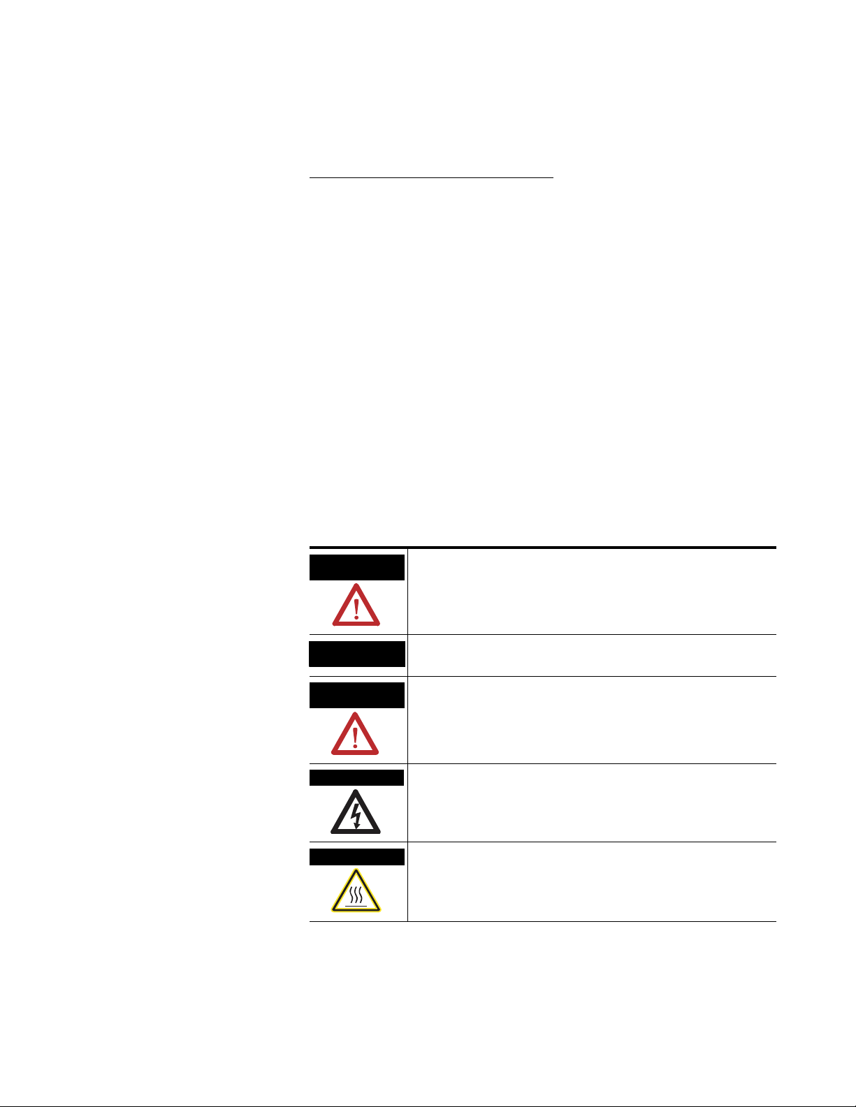
WARNING
Identifies information about practices or circumstances that can cause
an explosion in a hazardous environment, which may lead to personal
injury or death, property damage, or economic loss.
IMPORTANT
ATTENTION
Identifies information that is critical for successful application and
understanding of the product.
Identifies information about practices or circumstances that can lead
to personal injury or death, property damage, or economic loss.
Attentions help you identify a hazard, avoid a hazard, and recognize
the consequence
SHOCK HAZARD
Labels may be located on or inside the equipment, for example, a drive
or motor, to alert people that dangerous voltage may be present.
BURN HAZARD
Labels may be located on or inside the equipment, for example, a drive
or motor, to alert people that surfaces may be at dangerous
temperatures.
Allen-Bradley, PLC, SLC, MicroLogix, PanelView, DTAM, and Rockwell Automation are trademarks of Rockwell Automation, Inc.
Trademarks not belonging to Rockwell Automation are property of their respective companies.
Page 3

Summary of Changes
The information below summarizes the changes to this manual since
the last printing.
To help you find new and updated information in this release of the
manual, we have included change bars as shown to the right of this
paragraph.
Topic Page
Updated publication list 4
Ordering publications 4
Processor/cable compatibility 16...19
3 Publication 1761-UM004B-EN-P - June 2006
Page 4

4 Summary of Changes
Publication 1761-UM004B-EN-P - June 2006
Page 5

Product Overview
Installation and Wiring
Table of Contents
Preface
Who Should Use This Manual . . . . . . . . . . . . . . . . . . . . . . . . 3
Purpose of This Manual. . . . . . . . . . . . . . . . . . . . . . . . . . . . . 3
Additional Resources . . . . . . . . . . . . . . . . . . . . . . . . . . . . 4
Conventions Used in This Manual . . . . . . . . . . . . . . . . . . . . . 4
Chapter 1
Description. . . . . . . . . . . . . . . . . . . . . . . . . . . . . . . . . . . . . . 5
Operation Modes . . . . . . . . . . . . . . . . . . . . . . . . . . . . . . . . . 6
Device Compatibility. . . . . . . . . . . . . . . . . . . . . . . . . . . . . . . 6
Chapter 2
Compliance to European Union Directives . . . . . . . . . . . . . . . 9
EMC Directive . . . . . . . . . . . . . . . . . . . . . . . . . . . . . . . . . 9
Low Voltage Directive . . . . . . . . . . . . . . . . . . . . . . . . . . . 9
Safety Considerations . . . . . . . . . . . . . . . . . . . . . . . . . . . . . 10
Mount the AIC+ Advanced Interface Converter. . . . . . . . . . . 11
Mount to a DIN Rail . . . . . . . . . . . . . . . . . . . . . . . . . . . 11
Mount to a Panel . . . . . . . . . . . . . . . . . . . . . . . . . . . . . 12
Wire the AIC+ Advanced Interface Converter . . . . . . . . . . . . 13
Wire the Power Supply . . . . . . . . . . . . . . . . . . . . . . . . . 13
Wire to the Network Ports . . . . . . . . . . . . . . . . . . . . . . . 14
Cable Choices. . . . . . . . . . . . . . . . . . . . . . . . . . . . . . . . . . . 16
Recommended User-supplied Components . . . . . . . . . . . . . 19
Network Connections
Interpret the LED Indicators
Chapter 3
Network Diagrams . . . . . . . . . . . . . . . . . . . . . . . . . . . . . . . 21
Point-to-point Isolator . . . . . . . . . . . . . . . . . . . . . . . . . . 21
Components Replaced by the AIC+ Interface Converter . 22
DH-485 Network with SLC 5/03 and SLC 5/04 Processors
and a PC . . . . . . . . . . . . . . . . . . . . . . . . . . . . . . . . . . . . 23
DH-485 Network with a MicroLogix 1000 Controller . . . . 24
Typical Three-node OEM Network . . . . . . . . . . . . . . . . 24
Networked Operator-interface Device and MicroLogix
Controller . . . . . . . . . . . . . . . . . . . . . . . . . . . . . . . . . . . 25
Networks Using Ganged Converters . . . . . . . . . . . . . . . 26
Network Extended to 2438 m (8000 ft) . . . . . . . . . . . . . 27
DF1 Master-slave Network with Modem . . . . . . . . . . . . . 28
Avoid Incorrect Connections . . . . . . . . . . . . . . . . . . . . . 29
Chapter 4
Diagnostics . . . . . . . . . . . . . . . . . . . . . . . . . . . . . . . . . . . . . 31
i Publication 1761-UM004B-EN-P - June 2006
Page 6

ii Table of Contents
Specifications and Dimensions
Appendix A
General Specifications . . . . . . . . . . . . . . . . . . . . . . . . . . . . . 33
Hardware Handshaking . . . . . . . . . . . . . . . . . . . . . . . . . 34
Auto Transmit Delay (turnaround time) per
Communication Rate . . . . . . . . . . . . . . . . . . . . . . . . . . . 35
Mounting Template . . . . . . . . . . . . . . . . . . . . . . . . . . . . 36
Index
Publication 1761-UM004B-EN-P - June 2006
Page 7

Preface
Read this preface to familiarize yourself with the rest of the manual.
This preface covers the following topics.
• Who should use this manual
• Purpose of this manual
• Conventions used in this manual
Who Should Use This Manual
Purpose of This Manual
Use this manual if you are responsible for designing, installing,
programming, or troubleshooting control systems that use
Allen-Bradley Small Logic controllers.
You should have a basic understanding of SLC 500 and MicroLogix
products and be able to interpret the ladder-logic instructions required
to control your application. If you do not, contact your local
Allen-Bradley representative for information on available training
courses before using this product.
This manual is a reference guide for the Advanced Interface Converter
(AIC+). This manual:
• gives you an overview of the AIC+ interface converter operation.
• explains the procedures to install and wire the AIC+ interface
converter.
3 Publication 1761-UM004B-EN-P - June 2006
Page 8

4 Preface
Additional Resources
The following documents contain additional information regarding
Rockwell Automation products.
Related Documentation
For Read This Document Document
Number
A guide to understanding and selecting SLC 500 products SLC 500 System Selection Guide 1747-SG001
A description on how to install and use your modular SLC 500
programmable controller
A description on how to install and use your MicroLogix 1000
programmable controller
A description on how to install and use your MicroLogix 1200
programmable controller
A description on how to install and use your MicroLogix 1100
programmable controller
A description on how to install and use your MicroLogix 1500
programmable controller
A guide to DF1 protocol Data Highway/Data Highway Plus/Data Highway
A guide to wiring and grounding guidelines Industrial Automation Wiring and Grounding
A glossary of industrial automation terms and abbreviations Allen-Bradley Industrial Automation Glossary AG-7.1
User Manual for Modular Hardware Style
Programmable Controllers
MicroLogix 1000 Programmable Controller User
Manual
MicroLogix 1200 Programmable Controller User
Manual
MicroLogix 1100 Programmable Controller User
Manual
MicroLogix 1500 Programmable Controller User
Manual
II/Data Highway-485 Cable
Guidelines
1747-UM011
1761-UM003
1762-UM001
1763-UM001
1764-UM001
1770-UM022
1770-IN041
Conventions Used in This Manual
If you would like a manual, you can:
• download a free electronic version from the Internet at
http://literature.rockwellautomation.com
.
• purchase a printed manual by contacting your local distributor
or Rockwell Automation representative.
The following conventions are used throughout this manual.
• Bulleted lists, such as this one, provide information, not
procedural steps.
• Numbered lists provide sequential steps or hierarchical
information.
• Bold type is used for emphasis
Publication 1761-UM004B-EN-P - June 2006
Page 9

Product Overview
Chapter
1
Description
The AIC+ advanced interface converter provides a communication
link between various networked devices. The AIC+ interface converter
is compatible with a variety of SLC and MicroLogix controllers and
peripherals.
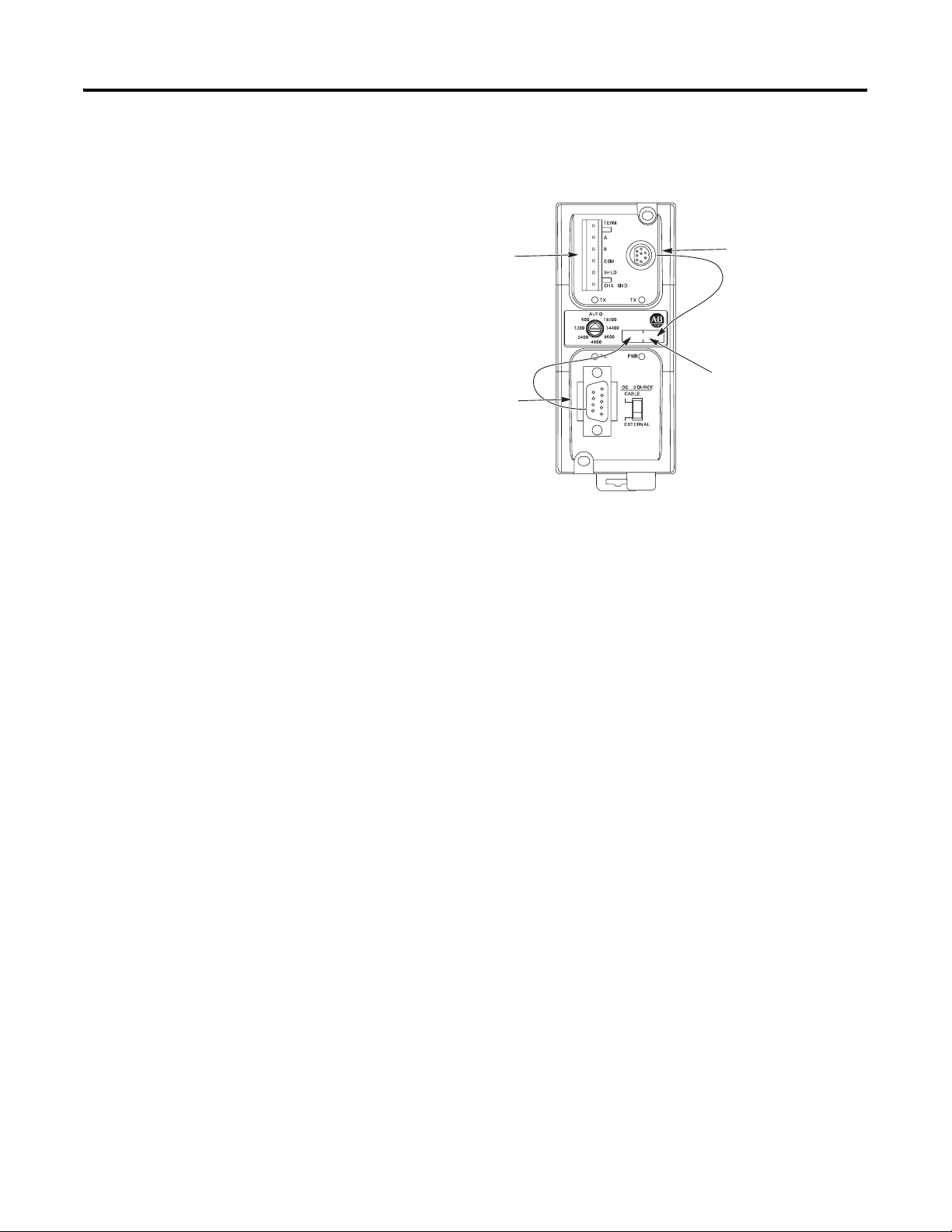
Communication Port and Switch Locations
RS-485
Communication Port
(Phoenix Plug)
Communication-rate
Selector Switch
RS-232 (DB-9, DTE)
Communication Port
RS-232 (8-pin mini-DIN)
Communication Port
DC Power-source
Selector Switch
Terminals for external 24V dc power
supply and chassis ground.
MicroLogix 1000, 1200, and 1500 controllers provide power to the
AIC+ interface converter via the RS-232 8-pin mini-DIN port’s cable.
However, if a MicroLogix controller is not connected to this port, a
24V dc power supply connected to the converter’s external power
terminals is required. The dc power-source selector switch needs to
be set for your particular configuration.
See Network Diagrams starting on page 21 for more details on how to
wire and configure the AIC+ interface converter.
5 Publication 1761-UM004B-EN-P - June 2006
Page 10

6 Product Overview
The communication-rate selector switch is used to match the
communication rate filter of the AIC+ interface converter to the
network communication rate. This switch does not change the
network communication rate and is normally left in the AUTO
position. In high noise environments, the communication-rate selector
switch should be taken out of the AUTO mode and set to the same
communication rate as the network.
See Auto Transmit Delay on page 35 for more information on
communication rates.
Operation Modes
Device Compatibility
The AIC+ interface converter can be used in the following modes.
• Point-to-point isolator
• RS-232 to RS-485 isolator
• RS-232 to half-duplex user mode ASCII isolator
Communication is established using hardware handshaking or auto
transmit signals.
The AIC+ interface converter can be used to interconnect the
following devices.
• SLC 500, 5/01, 5/02, and 5/03 processors (channel 1)
• SLC 5/03, 5/04, and 5/05 processors (channel 0)
• MicroLogix controllers
• Logix controllers
• 1756-DH485 ControlLogix module
• Operator interface devices
• Personal computer serial ports (or any 9-pin DTE serial port)
• Modems
Publication 1761-UM004B-EN-P - June 2006
TIP
You cannot connect the 1761-HHP-B30 Hand-held Programmer
to the AIC+ advanced interface converter.
Page 11
Node Address Identification
Product Overview 7
There is no node
address associated
with the network
port.
The node address is
configured in the
device connected
with this port.
The node address is
configured in the
device connected
with this port.
Use this area to mark
the node address of
each connection.
Publication 1761-UM004B-EN-P - June 2006
Page 12

8 Product Overview
Publication 1761-UM004B-EN-P - June 2006
Page 13

Installation and Wiring
Chapter
2
Compliance to European Union Directives
If this product has the CE mark it is approved for installation within
the European Union and EEA regions. It has been designed and tested
to meet the following directives.
EMC Directive
This product is tested to meet Council Directive 89/336/EEC
Electromagnetic Compatibility (EMC) and the following standards, in
whole or in part, documented in a technical construction file.
• EN 50081-2 EMC – Generic Emission Standard, Part 2 – Industrial
Environment
• EN 50082-2 EMC – Generic Immunity Standard, Part 2 –
Industrial Environment
This product is intended for use in an industrial environment.
Low Voltage Directive
This product is tested to meet Council Directive 73/23/EEC Low
Voltage, by applying the safety requirements of EN 61131–2
Programmable Controllers, Part 2 – Equipment Requirements and
Tests.
For specific information required by EN 61131-2, see the appropriate
sections in this publication, as well as the Industrial Automation
Wiring and Grounding Guidelines, publication 1770-IN041.
9 Publication 1761-UM004B-EN-P - June 2006
Page 14
10 Installation and Wiring
Safety Considerations
This equipment is suitable for use in Class I, Division 2, Groups A, B,
C, D, or nonhazardous locations only.
ATTENTION
Explosion Hazard —
Substitution of components may impair suitability for Class I,
Division 2.
Do not replace components or disconnect equipment unless
power is switched off and the area is known to be
nonhazardous.
Do not connect or disconnect connectors or operate switches
while circuit is live unless the area is known to be
nonhazardous.
This product must be installed in an enclosure. All cables
connected to the product must remain in the enclosure or be
protected by conduit or other means.
AIC+ interface converter must be operated from an external
power source.
All wiring must comply with N.E.C. articles 501, 502, 503,
and/or C.E.C. Section 18-1J2, as appropriate.
Use only the following communication cables and replacement
connectors in Class I, Division 2, hazardous locations.
Communication Cables for Class 1, Div Environments
Environment Classification Communication Cables
Class I, Division 2 Hazardous Environment 1761-CBL-PM02 (Series C or later)
1761-CBL-HM02 (Series C or later)
1761-CBL-AM00 (Series C or later)
1761-CBL-AP00 (Series C or later)
2707-NC8 (Series B)
2707-NC9 (Series B)
2707-NC10 (Series B)
2707-NC11 (Series B)
1746-RT30 AIC+ Connector
Publication 1761-UM004B-EN-P - June 2006
Page 15

Installation and Wiring 11
Mount the AIC+ Advanced Interface Converter
The AIC+ interface converter can be mounted in the vertical or
horizontal position. There are no spacing requirements except as
necessary for DIN-rail latch movement.
Mount to a DIN Rail
Follow these steps to install your interface converter.
1. Mount your DIN rail.
2. Snap the DIN-rail latch into the closed position.
3. Hook the top slot over the DIN rail.
Side View
DIN Rail
Latch
4. While pressing the AIC+ interface converter against the rail, snap
the AIC+ interface converter into position.
Follow these steps to remove your interface converter.
1. Place a screwdriver in the DIN-rail latch at the bottom of the
AIC+ interface converter.
2. Holding the AIC+ interface converter, pry downward on the
latch until the AIC+ interface converter is released from the DIN
rail.
Publication 1761-UM004B-EN-P - June 2006
Page 16

12 Installation and Wiring
Side View
DIN Rail
Mount to a Panel
Follow these instructions to mount your AIC+ interface converter to a
panel.
1. Remove the mounting template from this document.
2. Secure the template to the mounting surface.
3. Drill holes through the template.
4. Remove the mounting template.
5. Mount the AIC+ interface converter.
Mounting
Tem pl at e
Publication 1761-UM004B-EN-P - June 2006
Page 17

Installation and Wiring 13
Wire the AIC+ Advanced Interface Converter
This section provides power supply wiring and network port wiring
information.
Wire the Power Supply
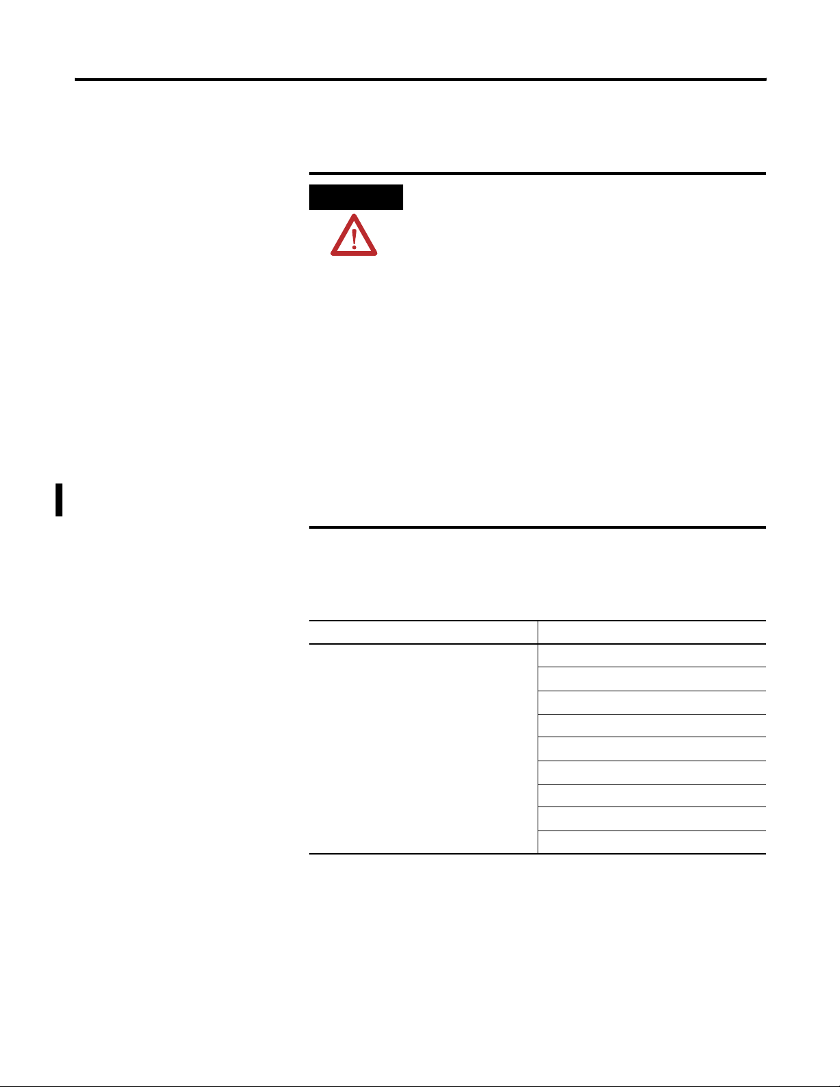
ATTENTION
IMPORTANT
Power Supply
EXPLOSION HAZARD —
An external power supply must be used in Class I, Division 2
applications and the dc power-source selector switch must be
in the EXTERNAL position before connecting the power supply
to the AIC+ interface converter.
In nonhazardous locations, external power is not required if the
AIC+ interface converter 8-pin mini-DIN com port is connected
to a MicroLogix controller.
Bottom
View
24VDC
DC
NEUT
CHS
GND
IMPORTANT
Some devices provide power to the AIC+ interface converter via
the 8-pin mini-DIN com port cable. The dc power-source
selector switch needs to be set for your particular
configuration.
If you are using a 1746-P1 or 1746-P2 power supply, the AIC+
interface converter is the only device that can be connected to
that power supply.
Always connect the CHS GND (chassis ground) terminal to the
nearest earth ground. This connection must be made whether
or not an external 24V dc supply is used.
Publication 1761-UM004B-EN-P - June 2006
Page 18

14 Installation and Wiring
Wire to the Network Ports
Use these instructions for wiring Belden cable.
Attach the RS-485 Connector to the Communication Cable
IMPORTANT
A daisy-chained network is recommended. Other chained
networks are not recommended.
Daisy-chain Network
Incorrect
Belden
#3106A
#9842
or
Connector
Belden
#3106A or
#9842
Connector
Belden
#3106A or
#9842
Connector
Attach the connector to the Belden #3106A or #9842 cable as shown
below.
Single Cable Connection
Orange with White Stripes
White with Orange Stripes
Shrink Tubing
Recommended
Blue (#3106A) or
Blue with White Stripes (#9842)
6 Termination
5A
4B
3
2 Shield
1 Chassis Ground
Drain Wire
Common
Publication 1761-UM004B-EN-P - June 2006
Multiple Cable Connection
to Previous Device
to Successive Device
Page 19

Installation and Wiring 15
The table below shows connections for Belden #3106A.
Belden #3106A Cable
For This Wire/Pair Connect This Wire To This Te rmina l
Shield/Drain Non-jacketed Terminal 2 – Shield
Blue Blue Terminal 3 – (Common)
White/Orange White with Orange Stripe Terminal 4 – (Data B)
Orange with White Stripe Terminal 5 – (Data A)
The table below shows connections for Belden #9842.
Belden #9842 Cable
For This Wire/Pair Connect This Wire To This Te rmina l
Shield/Drain Non-jacketed Terminal 2 – Shield
Blue/White White with Blue Stripe Cut back – no connection
Blue with White Stripe Terminal 3 – (Common)
White/Orange White with Orange Stripe Terminal 4 – (Data B)
(1)
Orange with White Stripe Terminal 5 – (Data A)
(1)
To prevent confusion when installing the communication cable, trim the white and blue striped wire
immediately after the insulation jacket is removed. This wire is not used by DH-485.
Only one connector at the end of the link must have Terminals 1 and
2 jumpered together. This provides an earth-ground connection for
the shield of the communication cable.
Both ends of the network must have Terminals 5 and 6 jumpered
together. This connects the termination impedance (120
Ω) that is built
into each AIC and AIC+ interface converter as required by the RS-485
specification.
End of Line Termination
Jumper
Belden
#3106A or #9842 Cable
1219 m (4000 ft) Maximum
Jumper
Jumper
Publication 1761-UM004B-EN-P - June 2006
Page 20

16 Installation and Wiring
Cable Choices
This section provides information that will help you determine the
appropriate cable for your application.
1761-CBL-AC00 and 1747-CP3 Cable
1747-CP3
1761-CBL-AC00
1761-CBL-AC00 and 1747-CP3 Cable
Cable Length Connects
from to AIC+
Interface
Converter
1747-CP3,
1761-CBL-AC00
3 m (9.8 ft),
45 cm (17.7 in.)
SLC 5/03, SLC 5/04, or SLC 5/05
processor, channel 0
PC com port RS-232 (DB-9,
RS-232 (DB-9,
DTE)
Communication
Port
DTE)
Communication
Port
PanelView through NULL modem
adapter
RS-232 (DB-9, DTE) Communication
Port on another AIC+ interface
converter
RS-232 (DB-9,
DTE)
Communication
Port
RS-232 (DB-9,
DTE)
Communication
Port
Publication 1761-UM004B-EN-P - June 2006
Page 21

1761-CBL-AS03 and 1761-CBL-AS09 Cable
1761-CBL-AS03
1761-CBL-AS03 and 1747-CBL-AS09 Cable
Cable Length Connects
from to AIC+
1761-CBL-AS03,
1761-CBL-AS09
3 m (9.8 ft),
9.9 m (29.5 ft)
SLC 500 Fixed, SLC 5/01, SLC 5/02,
and SLC 5/03 processors
PanelView RJ45 port RS-485
Installation and Wiring 17
1761-CBL-AS09
Interface
Converter
RS-485
Communication
Port (Phoenix
Plug)
Communication
Port (Phoenix
Plug)
1761-CBL-AM00 and 1761-CBL-HM02 Cable
1761-CBL-HM02
1761-CBL-AM00
1761-CBL-AM00 and 1761-CBL-HM02 Cable
Cable Length Connects External
Power
from to AIC+
Interface
Supply
Required
Converter
1761-CBL-AM00
1761-CBL-HM02
(1)
45 cm
(17.7 in.),
2 m
(6.5 ft)
MicroLogix
1000, 1200, and
1500
processors
RS-232 (8-pin
mini-DIN)
communication
port on another
RS-232 (8-pin
mini-DIN)
communication
port
RS-232 (8-pin
mini-DIN)
communication
port
No Cable
Yes External
AIC+ interface
converter or
MicroLogix
1100
(1)
Series B cables are required for hardware handshaking.
Selection
Switch
Setting
Publication 1761-UM004B-EN-P - June 2006
Page 22

18 Installation and Wiring
1761-CBL-AP00 and 1761-CBL-PM02 Cable
1761-CBL-AP00
1761-CBL-PM02
1761-CBL-AP00 and 1761-CBL-PM02 Cable
Cable Length Connects External
Power
Supply
Required
Yes External
1761-CBL-AP00,
1761-CBL-PM02
(1)
45 cm,
(17.7 in.),
2 m
(6.5 ft)
from to AIC+
Interface
Converter
SLC 5/03, SLC
5/04, or SLC
5/05
processors,
RS-232 (8-pin
mini-DIN)
communication
port
channel 0
MicroLogix
1000, 1200,
and 1500
processors
PanelView
through NULL
modem adapter
RS-232 (DB-9,
DTE)
Communication
Port
RS-232 (8-pin
mini-DIN)
communication
(2)
Yes
Yes External
port
(1)
Selection
Switch
Setting
External
PC com port RS-232 (8-pin
Yes External
mini-DIN)
communication
port
(1)
Series B cables are required for hardware handshaking.
(2)
An external power supply is required unless the AIC+ interface converter is powered by a MicroLogix controller
connected to the RS-232 (8-pin mini-DIN) communication port with a 1761-CBL-AM00 or 1761-CBL-HM02 or
equivalent cable.
Publication 1761-UM004B-EN-P - June 2006
Page 23

User-supplied Cable
User-supplied Cable
Cable Length Connects
from to AIC+ Interface
Straight through 9
pin
— Modem or other
communication device
Installation and Wiring 19
User-supplied Cable
Converter
RS-232 (DB-9, DTE)
communication port
Recommended User-supplied Components
These components can be purchased from your local electronics
supplier.
User-supplied Components
Component Recommended Model
External power supply and
chassis ground
NULL modem adapter Standard AT
Straight through 9 pin RS-232
cable
User-supplied Components
DB-9 RS-232
Port 1
6
7
8
9
1
2
3
4
5
Power supply rated for 20.4...28.8V dc
User-supplied cable
1761-CBL-AP00 or 1761-CBL-PM02
Cable Straight-D Connector
Port 2
678
3
4
5
12
DH-485 Connector
Port 3
6
5
4
3
2
1
Publication 1761-UM004B-EN-P - June 2006
Page 24

20 Installation and Wiring
Ports
Pin # DB-9 RS-232 RS-232 (8-pin mini-DIN)
Communication Port
Port 3
(1)
DH-485 Connector
(1761-CBL-PM02 cable)
1 Received line signal
Not applicable Chassis ground
detector (DCD)
2 Received data (RxD) Signal common (GRD) Cable shield
3 Transmitted data (TxD) Request to send (RTS) Signal ground
4 DTE ready (DTR) Received data (RxD) DH-485 data B
5 Signal common (GRD) Same state as port 1’s
DH-485 data A
DCD signal
6 DCE ready (DSR) Clear to send (CTS) Termination
7 Request to send (RTS) Transmitted data (TxD) Not applicable
8 Clear to send (CTS) Not applicable Not applicable
9 Not applicable Not applicable Not applicable
(1)
An 8-pin mini-DIN connector is used for making connections to the RS-232 (8-pin mini-DIN) communication
port. This connector is not commercially available. If you are making a cable to connect to the RS-232 (8-pin
mini-DIN) communication port, you must configure your cable to connect to the Allen-Bradley cable.
Publication 1761-UM004B-EN-P - June 2006
Page 25

Network Connections
Chapter
3
Network Diagrams
This chapter provides various network connections. The item number
provided in the Communication Port table corresponds to the
designated port on the AIC+ advanced interface converter shown in
each illustration.
Communication Port
Item Number Port
1 RS-232 (DB-9, DTE) com port
2 RS-232 (8-pin mini-DIN) com port
3 RS-485 com port
Point-to-point Isolator
Point-to-point Isolator
MicroLogix
AIC+ Converter
3
2
1
1761-CBL-AM00 or
1761-CBL-HM02 Cable
1747-CP3 or 1761-CBL-AC00 Cable
1000 Processor
PC
24V dc
(Not needed in this
configuration since the
MicroLogix 1000 processor provides
power to the RS-232 (8-pin mini DIN) com port.)
21 Publication 1761-UM004B-EN-P - June 2006
Page 26

22 Network Connections
Components Replaced by the AIC+ Interface Converter
The AIC+ interface converter replaces the combination of a 1747-PIC
interface converter and 1747-AIC isolated link coupler in most
applications.
Components Replaced by the AIC+ Interface Converter
DH-485 Network using 1747-AIC Interface Converter
SLC 5/04 Processor
24V
dc Power
1747-PIC
Interface
Converter
1747-AIC Isolated
Link Coupler
DH-485 Network using 1747-AIC+ Interface Converter
SLC 5/04 Processor
3
2
AIC+
Converter
1747-AIC Isolated
Link Coupler
SLC 5/02 Processor SLC 5/03 Processor
1747-AIC Isolated
Link Coupler
1747-AIC Isolated
Link Coupler
1747-AIC Isolated
Link Coupler
Publication 1761-UM004B-EN-P - June 2006
24V dc Power
SLC 5/02 Processor
SLC 5/03 Processor
Page 27

DH-485 Network with SLC 5/03 and SLC 5/04 Processors and a PC
DH-485 Network with SLC 5/03 and SLC 5/04 Processors and a PC
dc Power
24V
1761-CBL-AP00 or
1761-CBL-PM02 Cable
AIC+ Converter
3
2
1
SLC 5/03 or SLC 5/04 Processor
Connection from Processor
Channel 0
1747-CP3 or
1761-CBL-AC00
Cable
PC
APS
1761-CBL-AP00 or
1761-CBL-PM02 Cable
3
2
AIC+ Converter
1
24V dc
(user
supplied)
Network Connections 23
1747-CP3 or
1761-CBL-AC00 Cable
SLC
DH-485 Network
1747-AIC Isolated
Link Coupler
SLC 5/02 Processor
1747-AIC Isolated
Link Coupler
SLC 5/03 Processor
Publication 1761-UM004B-EN-P - June 2006
Page 28

24 Network Connections
DH-485 Network with a MicroLogix 1000 Controller
DH-485 Network with a MicroLogix 1000 Controller
MicroLogix 1000 Processor (series C or later)
1761-CBL-AM00 or
1761-CBL-HM02 Cable
AIC+ Converter
2
3
1
24V dc
(User supply needed
if using RS-232 (DB-9, DTE) com port.)
Typical Three-node OEM Network
Connection from
Port 1 or Port 2
to MicroLogix 1000 Processor
1761-CBL-AP00 or
1761-CBL-PM02 Cable
PC
1761-CBL-AP00 or
1761-CBL-PM02 Cable
3
2
AIC+ Converter
1
24V dc
(user supplied)
1747-CP3 or
1761-CBL-AC00 Cable
Typical Three-node Network
PanelView Operator Interface
RJ45 Port
1761-CBL-AS09 or 1761-CBL-AS03 Cable
MicroLogix 1000 Processor (series C or later)
1761-CBL-AM00 or
1761-CBL-HM02 Cable
AIC+ Converter
3
2
1
24V dc
(Not needed in this
configuration since the
MicroLogix 1000 processor
provides power to the
AIC+ interface converter.)
PC
1747-CP3 or 1761-CBL-AC00 Cable
Publication 1761-UM004B-EN-P - June 2006
Page 29

Network Connections 25
Networked Operator-interface Device and MicroLogix Controller
Networked Operator-interface Device and MicroLogix Controller
PanelView 550 Operator Interface
PC
1761-CBL-AP00 or
1761-CBL-PM02 Cable
AIC+ Converter
2
3
1
24V dc
(user supplied)
SLC DH-485 Network
RS-232 Port
NULL Modem
Adapter
Connection from NULL Modem
Adapter
1747-CP3 or
1761-CBL-AC00 Cable
1747-AIC
Isolated Link Coupler
SLC 5/03 Processor
1761-CBL-AP00 or
1761-CBL-PM02 Cable
AIC+ Converter
3
1
(user supplied)
AIC+ Converter
3
2
24V dc
(Not needed in this
configuration since
the MicroLogix
1000 provides
power to the AIC+
via port 2.)
1747-CP3 or
1761-CBL-AC00 Cable
2
24V dc
1761-CBL-AM00 or
1761-CBL-HM02 Cable
MicroLogix 1000 Processor (series C or later)
Publication 1761-UM004B-EN-P - June 2006
Page 30

26 Network Connections
Networks Using Ganged Converters
Networks Using Ganged Converters
DH-485 Network with PanelView Interface
PanelView Interface
RJ45 Port
1761-CBL-AS09 or
1761-CBL-AS03 Cable
AIC+ Converter
1761-CBL-AS09 or
1761-CBL-AS03 Cable
2
3
24V dc
(user supplied)
Network
SLC 500 Fixed Controller
RJ45 Port
1761-CBL-AM00 or
3
1
(user supplied)
DH-485
24V dc power
1761-CBL-AM00 or
1761-CBL-HM02 Cable
2
AIC+ Converter
24V dc
1761-CBL-HM02 Cable
1747-CP3
PC
or 1761-CBL-AC00 Cable
PC
Publication 1761-UM004B-EN-P - June 2006
AIC+ Converter
2
DH-485
Network
3
1
2
AIC+ Converter
1747-CP3 or
1761-CBL-AC00 Cable
3
Page 31

Network Extended to 2438 m (8000 ft)
Network Extended to 2438 m (8000 ft)
DH-485 Network
1219 m (4000 ft), Maximum
Extended DH-485 network
2438 m (8000 ft), maximum
and 32 nodes total.
1761-CBL-AM00 or
1761-CBL-HM02 Cable
3
2
AIC+ Converter
AIC+ Converter
2
3
Network Connections 27
24V dc
(User supplied or
from 24V dc terminals
on SLC controller.)
24V dc
(User supplied or
from 24V dc terminals
on SLC controller.)
DH-485 Network
1219 m (4000 ft), Maximum
Publication 1761-UM004B-EN-P - June 2006
Page 32

28 Network Connections
DF1 Master-slave Network with Modem
DF1 Master-slave Network with Modem
SLC 5/03 Processor
CH0
DF1
Master
3
AIC+ Converter
1
SLC 5/03 processor
CH0
DF1
Slave
3
2
1
1761-CBL-AP00 or
1761-CBL-PM02 Cable
2
Straight 9...25 Pin Cable
1761-CBL-AP00 or
1761-CBL-PM02 Cable
1747-CP3 or
1761-CBL-AC00 Cable
Radio Modem
or Lease Line
Radio Modem
or Lease Line
Straight
9...25
Pin Cable
SLC 5/03 Processor
CH0
DF1
Slave
3
2
AIC+ Converter
1
SLC 5/03 Processor
CH0
DF1
Slave
3
2
1
1761-CBL-AP00 or
1761-CBL-PM02 Cable
1761-CBL-AP00 or
1761-CBL-PM02 Cable
1747-CP3 or
1761-CBL-AC00 Cable
AIC+ Converter
AIC+ Converter
Use this diagram for user-mode ASCII as well as DF1 master-slave
protocol.
See Specifications for more information on hardware handshaking and
communication protocols.
Publication 1761-UM004B-EN-P - June 2006
Page 33

Avoid Incorrect Connections
Incorrect Connections
1747-AIC Isolated
Link Coupler
DH-485
Network
1761-CBL-AS09 or
1761-CBL-AS03 Cable
AIC+ Converter
3
DH-485
Network
Network Connections 29
1761-CBL-AS09 or
1761-CBL-AS03 Cable
1747-AIC Isolated
Link Coupler
IMPORTANT
SLC 5/03 Processor
In this configuration, the cable will fit but not function properly.
Publication 1761-UM004B-EN-P - June 2006
Page 34

30 Network Connections
Publication 1761-UM004B-EN-P - June 2006
Page 35

Interpret the LED Indicators
Chapter
4
Diagnostics
LED Indicators and Selector Switch
TX RS-485 LED Indicator
TX RS-232 (9-pin) LED
Indicator
LED Indicator Status
LED Indicator Status Condition
TX RS-232 9-pin Flashing Transmitting.
TX RS-232 (8-pin
mini-DIN) LED Indicator
PWR (Power) LED
Indicator
DC Power-source
Selector Switch
Off Receiving or idle.
TX RS-232 8-pin Flashing Transmitting.
Off Receiving or idle.
TX RS-485 Flashing Transmitting.
Off Receiving or idle.
PWR – Power OK On Power OK.
Off No power to AIC+ interface converter or dc
source switch set incorrectly.
Power Source
Selection Switch
31 Publication 1761-UM004B-EN-P - June 2006
Cable 24V dc power supplied to AIC+ interface
converter from device connected to RS-232
(8-pin mini-DIN) communication port.
External 24V dc power supplied to AIC+ interface
converter from external source (use 24V dc
power from SLC or user-supplied 24V dc
power supply).
Page 36

32 Interpret the LED Indicators
Publication 1761-UM004B-EN-P - June 2006
Page 37

Specifications and Dimensions
Appendix
A
General Specifications
AIC+ Advanced Interface Converter - 1761-NET-AIC
Attribute Value
24V dc Power Source
Requirement
Current Draw 0...120 mA
Internal Isolation (see below) 500V dc
DH-485, DF1, or User Network • Number of nodes, max = 32 per multidrop network
Environmental Specifications
Attribute Value
Operating Ambient Temperature 0...60 °C (32...140 °F)
Storage Temperature -40...85 °C (-40...175 °F)
Certifications
Certification Value
Agency Certification
(1)
See the Product Certification link at http:ab.com for Declaration of Conformity, certificates, and other
certification details.
(1)
20.4...28.8V dc
200 mA inrush current, max
• Length, max = 1219 m (4000 ft) per multidrop
network
• Number of ganged multidrop networks, max = 2
• UL 1604
• C-UL C22.2 No. 213
• Class I Division 2 Groups A, B, C, D
• CE compliant for all applicable
directives
33 Publication 1761-UM004B-EN-P - June 2006
Page 38

34 Specifications and Dimensions
Isolation Between All Ports and Power Supply Terminals
RS-485 Communication
Port (Phoenix Plug)
RS-232 (DB-9, DTE)
Communication Port
Terminals for external 24V dc power
supply and chassis ground.
RS-232 (8-pin mini-DIN)
Communication Port
Hardware Handshaking
To implement hardware handshaking, use cables that support the
following signals.
Signals Needed for Hardware Handshaking
Signal Definition Function
RTS active An input to AIC+ interface converter port.
CTS active An output from AIC+ interface converter
port.
When hardware handshaking is used, the auto transmit delay
(turnaround time) is zero.
Protocol for Hardware Handshaking
Protocol AIC+ Interface Converter Support of
Hardware Handshaking
DF1 Full-duplex (point-to-point isolator)
DF1 Master-slave Yes
User-mode ASCII
(1)
You can connect two DF1 Full-duplex devices together with one AIC+ interface converter.
(2)
Any communication coming off of the RS-485 line will not drive the carrier detect lines on the RS-232 (DB-9,
DTE) communication port and the RS-232 (8-pin mini-DIN) communication port. If the devices require carrier
detect high, it must be jumpered high locally at the device’s RS-232 port. Devices on RS-232 (DB-9, DTE)
communication port and RS-232 (8-pin mini-DIN) communication port can drive the other RS-232 ports
handshaking lines and the RS-485 transmitter.
Yes
Yes
(1)
(2)
(2)
Publication 1761-UM004B-EN-P - June 2006
Page 39

Specifications and Dimensions 35
Auto Transmit Delay (turnaround time) per Communication Rate
Communication
Rate (Kbps)
Min Delay
(ms)
Max Delay
(ms)
Typical Delay
(ms)
Pre-send
Transmit Delay
Setting (ms)
(1)
600 7.3 15.0 10.8 16
1200 7.3 15.0 10.8 16
2400 5.5 11.2 8.1 12
4800 2.7 5.7 4.0 6
9600 1.3 2.8 2.0 3
14400 0.9 1.9 1.4 2
19200 0.6 1.4 1.0 2
AUTO 0.3 0.7 0.5
(1)
The pre-send transmit delay setting is used in your device’s (for example, SLC and MicroLogix controller)
communications configuration.
(2)
Use a pre-send value, depending upon the network communication rate being used.
(2)
Auto-transmit Delay for AIC+ Interface Converter Using Auto-transmit Detection
(no hardware handshaking)
RS-485 Communication
Port (Phoenix Plug)
Network Device
Packet to
Network Device
Packet From
Network Device
Auto Transmit Delay
(turnaround time)
Auto Transmit Delay is measured from the time the AIC+ interface
converter transmits its last mark out of the RS-485 port, until the delay
time expires. The AIC+ interface converter will not accept RS-485 port
data during the Auto Transmit Delay time.
Publication 1761-UM004B-EN-P - June 2006
Page 40

36 Specifications and Dimensions
Mounting Template
52.07 mm (2.05 in.)
118 mm (4.64 in.)
107 mm (4.20 in.)
Allow 15 mm (0.6 in.) clearance
for DIN-rail latch movement
during installation and removal.
27.7 mm (1.09 in.)
Publication 1761-UM004B-EN-P - June 2006
Page 41

Index
A
AIC+ Advanced Interface Converter
compatibility with other devices 6
connect to a network 21
dimensions 36
LED indicators 31
mount 11
operating modes 6
product overview 5
specifications 33
wire 13
C
cables
1747-CP3 16
1761-CBL-AC00 16
1761-CBL-AM00 17
1761-CBL-AP00 18
1761-CBL-AS03 17
1761-CBL-AS09 17
1761-CBL-HM02 17
1761-CBL-PM02 18
user-supplied 19
compliance to European Union
directives
conventions used in this manual 4
9
N
networks
components replaced by AIC+ Advanced
Interface Converter
DF1 master-slave network with modem
28
DH-485 with a MicroLogix 1000
controller
DH-485 with SLC 5/03 and SLC 5/04
processors and a PC
extended to 2438 m (8000 ft) 27
incorrect connections 29
operator interface device and MicroLogix
controller
point-to-point isolator 21
typical three-node OEM 24
with ganged converters 26
24
25
22
23
O
operating modes 6
P
panel mount 12
product overview 5
purpose of manual 3
D
device compatibility 6
dimensions 36
DIN rail mount 11
H
hardware handshaking 34
L
LED indicators 31
M
mount the AIC+ Advanced Interface
Converter
DIN rail 11
panel mount 12
mounting template 36
R
related documentation 4
S
safety considerations 10
specifications 33
U
user-supplied components 19
W
who should use this manual 3
wire
network port 14
power supply 13
Publication 1761-UM004B-EN-P - June 2006
Page 42

2 Index
Publication 1761-UM004B-EN-P - June 2006
Page 43

How Are We Doing?
Your comments on our technical publications will help us serve you better in the future.
Thank you for taking the time to provide us feedback.
You can complete this form and mail (or fax) it back to us or email us at
RADocumentComments@ra.rockwell.com
Pub. Title/Type AIC+ Advanced Interface Converter User Manual
Cat. No. 1761-NET-AIC Pub. No. 1761-UM004B-EN-P Pub. Date June 2006 Part No.
Please complete the sections below. Where applicable, rank the feature (1=needs improvement, 2=satisfactory, and 3=outstanding).
Overall Usefulness 1 2 3 How can we make this publication more useful for you?
Completeness
(all necessary information
is provided)
Technical Accuracy
(all provided information
(all provided information is
correct)
is
Clarity
easy to understand)
1 2 3 Can we add more information to help you?
procedure/step illustration feature
example guideline other
explanation definition
1 2 3 Can we be more accurate?
t ex t illustration
1 2 3 How can we make things clearer?
Other Comments You can add additional comments on the back of this form.
Your Name
Your Title/Function Would you like us to contact you regarding your comments?
Location/Phone ___No, there is no need to contact me
___Yes, please call me
___Yes, please email me at _______________________
___Yes, please contact me via _____________________
Return this form to: Rockwell Automation Technical Communications, 1 Allen-Bradley Dr., Mayfield Hts., OH 44124-9705
Fax: 440-646-3525 Email: RADocumentComments@ra.rockwell.com
Publication CIG-CO521C-EN-P- May 2003 PNXXXXXX-XX957782-91
Page 44

Other Comments
PLEASE FASTEN HERE (DO NOT STAPLE)
PLEASE FOLD HERE
BUSINESS REPLY MAIL
FIRST-CLASS MAIL PERMIT NO. 18235 CLEVELAND OH
POSTAGE WILL BE PAID BY THE ADDRESSEE
NO POSTAGE
NECESSARY
IF MAILED
IN THE
UNITED STATES
PLEASE REMOVE
1 ALLEN-BRADLEY DR
MAYFIELD HEIGHTS OH 44124-9705
Page 45

Page 46

Rockwell Automation
Support
Rockwell Automation provides technical information on the Web to assist
you in using its products. At
find technical manuals, a knowledge base of FAQs, technical and application
notes, sample code and links to software service packs, and a MySupport
feature that you can customize to make the best use of these tools.
For an additional level of technical phone support for installation,
configuration, and troubleshooting, we offer TechConnect Support programs.
For more information, contact your local distributor or Rockwell Automation
representative, or visit
http://support.rockwellautomation.com, you can
http://support.rockwellautomation.com.
Installation Assistance
If you experience a problem with a hardware module within the first 24
hours of installation, please review the information that's contained in this
manual. You can also contact a special Customer Support number for initial
help in getting your module up and running.
United States 1.440.646.3223
Monday – Friday, 8am – 5pm EST
Outside United
States
Please contact your local Rockwell Automation representative for any
technical support issues.
New Product Satisfaction Return
Rockwell tests all of its products to ensure that they are fully operational
when shipped from the manufacturing facility. However, if your product is
not functioning, it may need to be returned.
United States Contact your distributor. You must provide a Customer Support case
number (see phone number above to obtain one) to your distributor in
order to complete the return process.
Outside United
States
Please contact your local Rockwell Automation representative for
return procedure.
Publication 1761-UM004B-EN-P - June 2006 7
Supersedes Publication 1761-6.4 - April 1998 Copyright © 2006 Rockwell Automation, Inc . All rights reserved. Printed in the U.S.A.
 Loading...