

Page 1

Installation Instructions
Universal Serial Bus (USB) to DH-485 Interface Converter
Catalog Number 1747-UIC
Contents…
Overview. . . . . . . . . . . . . . . . . . . . . . . . . . . . . . . . . . . . . . . . . . . . . . . . . .3
Computer and Operating System Requirements . . . . . . . . . . . . . . . . . . .3
Install the Interface Converter . . . . . . . . . . . . . . . . . . . . . . . . . . . . . . . . .3
Install the Ferrite Collar (European EMC Compliance) . . . . . . . . . . . . .4
Connect DH-485 Devices to the Interface Converter’s RS-485 Port . . . 5
Connect DH-485 Devices to the Interface Converter’s RS-232 Port . . . 6
Install the Drivers. . . . . . . . . . . . . . . . . . . . . . . . . . . . . . . . . . . . . . . . . .7
Identify the Assigned COM Port . . . . . . . . . . . . . . . . . . . . . . . . . . . . .11
Configure the 1747-UIC Interface Converter in RSLinx . . . . . . . . . . . .11
Uninstall the Drivers . . . . . . . . . . . . . . . . . . . . . . . . . . . . . . . . . . . . . .13
Change the Station Number . . . . . . . . . . . . . . . . . . . . . . . . . . . . . . . . . .14
Interpret the LED Indicators . . . . . . . . . . . . . . . . . . . . . . . . . . . . . . . . . .14
Specifications . . . . . . . . . . . . . . . . . . . . . . . . . . . . . . . . . . . . . . . . . . . . .15
Publication 1747-IN063C-EN-P - January 2006
Page 2
2 Universal Serial Bus (USB) to DH-485 Interface Converter
Important User Information
Solid state equipment has operational characteristics differing from those of electromechanical equipment.
Safety Guidelines for the Application, Installation and Maintenance of Solid State Controls, publication
SGI-1.1, available from your local Rockwell Automation sales office or online at
http://www.literature.rockwellautomation.com describes some important differences between solid state
equipment and hard-wired electromechanical devices. Because of this difference, and also because of the
wide variety of uses for solid state equipment, all persons responsible for applying this equipment must
satisfy themselves that each intended application of this equipment is acceptable.
In no event will Rockwell Automation, Inc. be responsible or liable for indirect or consequential damages
resulting from the use or application of this equipment.
The examples and diagrams in this manual are included solely for illustrative purposes. Because of the many
variables and requirements associated with any particular installation, Rockwell Automation, Inc. cannot
assume responsibility or liability for actual use based on the examples and diagrams.
No patent liability is assumed by Rockwell Automation, Inc. with respect to use of information, circuits,
equipment, or software described in this manual.
Reproduction of the contents of this manual, in whole or in part, without written permission of Rockwell
Automation, Inc. is prohibited.
Throughout this manual, when necessary we use notes to make you aware of safety considerations.
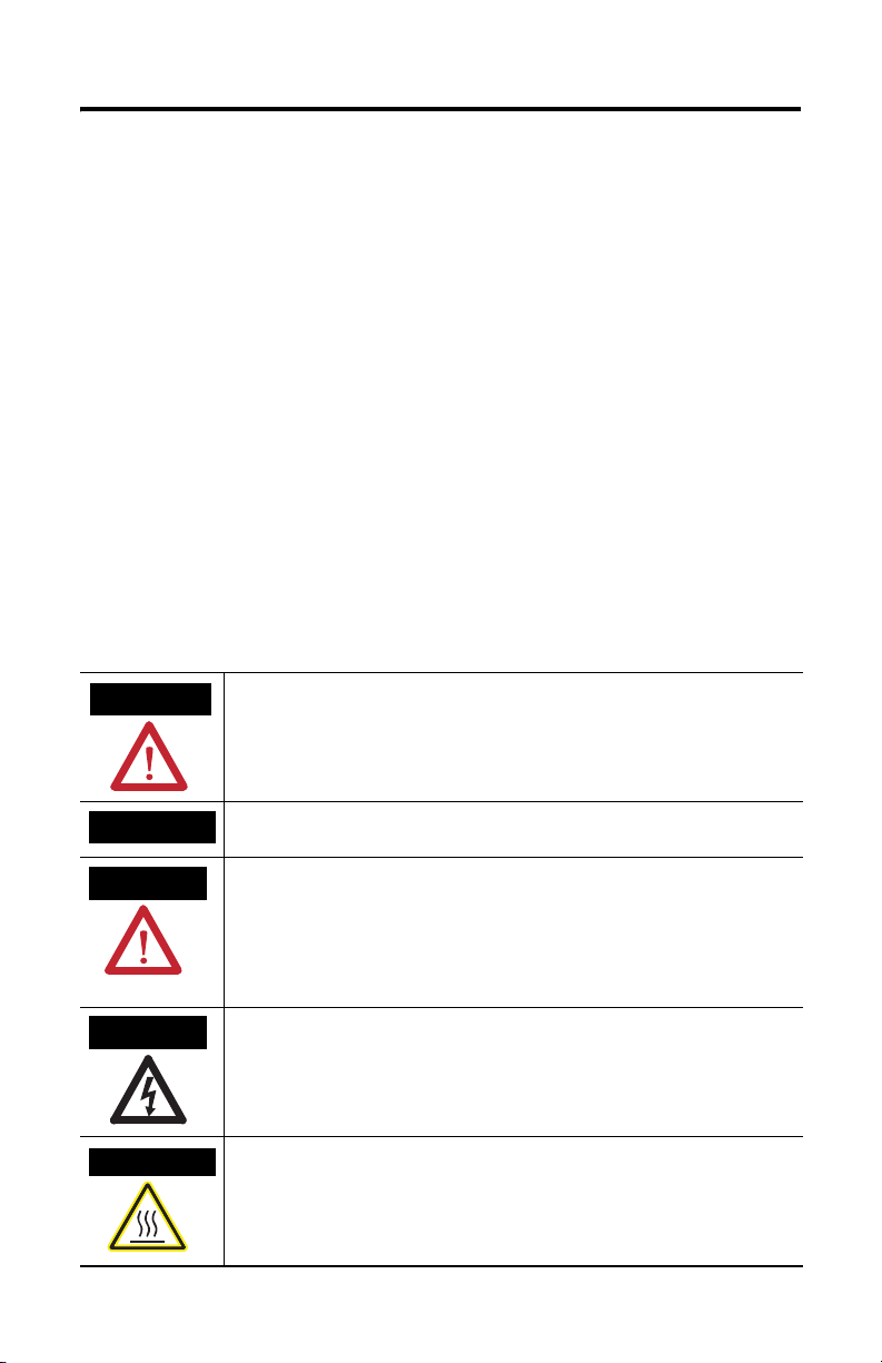
WARNING
Identifies information about practices or circumstances that can cause an explosion in a
hazardous environment, which may lead to personal injury or death, property damage,
or economic loss.
IMPORTANT
ATTENTION
SHOCK HAZARD
BURN HAZARD
Identifies information that is critical for successful application and understanding of the
product.
Identifies information about practices or circumstances that can lead to personal injury
or death, property damage, or economic loss. Attentions help you:
• identify a hazard
• avoid a hazard
• recognize the consequence
Labels may be located on or inside the equipment (for example, drive or motor) to alert
people that dangerous voltage may be present.
Labels may be located on or inside the equipment (for example, drive or motor) to alert
people that surfaces may be dangerous temperatures.
Publication 1747-IN063C-EN-P - January 2006
Page 3
Universal Serial Bus (USB) to DH-485 Interface Converter 3
RS485 (DH485)
RS232 (DH485)
SW
Mfg
XXXX
MADE IN INDIA
N223
RS485 (DH485)
RS232 (DH485)
SW
Mfg
XXXX
MADE IN INDIA
N223
Overview
The 1747-UIC allows you to connect devices that communicate using DH-485
protocol directly to a computer’s USB port, using either the 1747-UIC’s RS-232 or
RS-485 port and user-provided programming cables. Three LED indicators on the
1747-UIC provide communication status.
Computer and Operating System Requirements
The USB to DH-485 interface converter works with RSLinx version 2.41 or higher
and Windows98/2000/XP, on computers equipped with USB ports.
Install the Interface Converter
To install the interface converter:
1. Determine whether you will mount the interface converter. The interface
converter can be mounted on a DIN rail using the DIN rail mounting kit
(included).
2. Install the Ferrite Collar for EMC Compliance. See page 4.
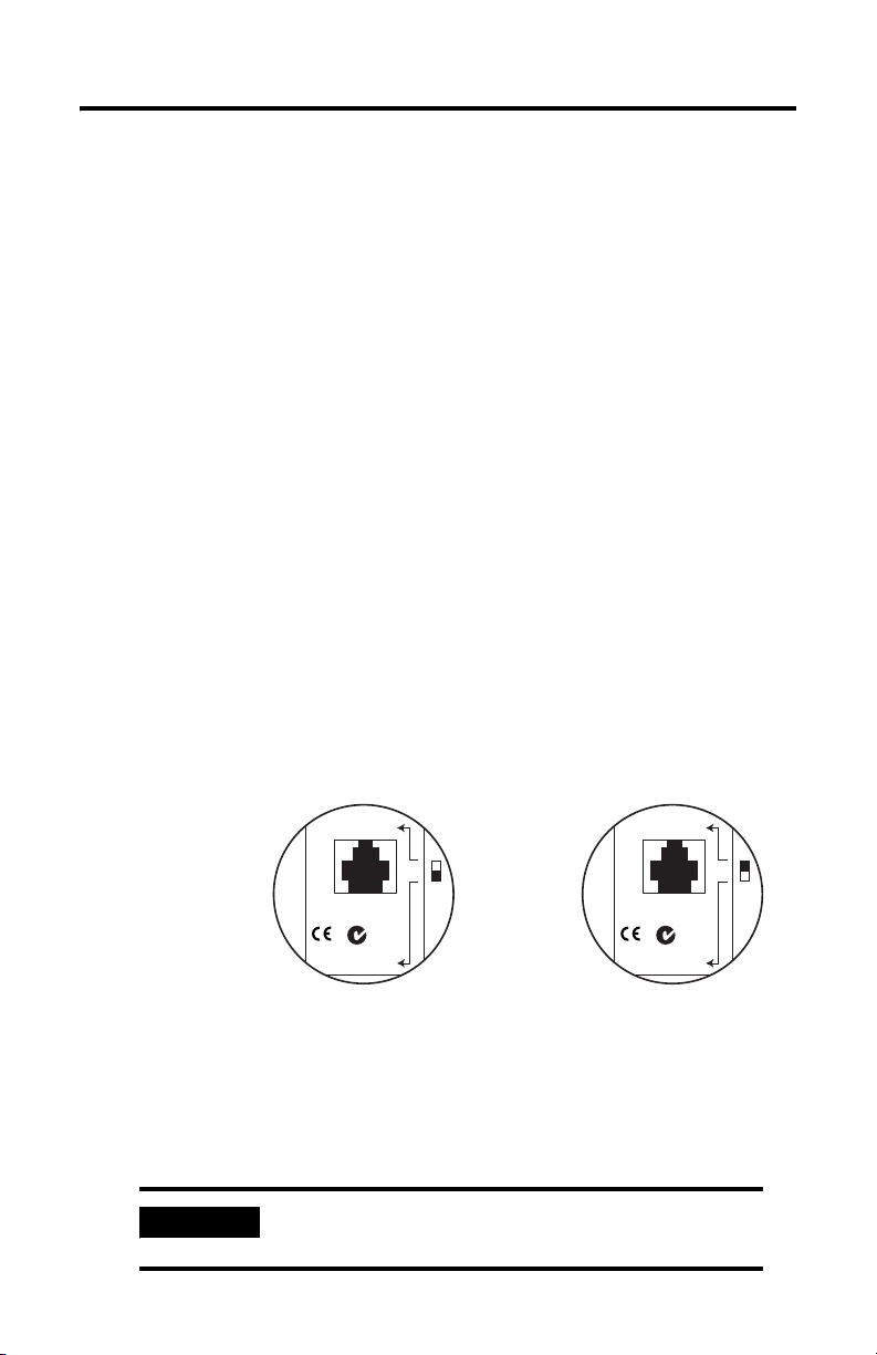
3. Slide the switch (SW) on the interface converter to indicate the appropriate
port.
Set for RS-232 Port
Set for RS-485 Port
4. To ensure proper ground, make cable connections between the interface
converter and the DH-485 device or interface first.
See Connect DH-485 Devices to the Interface Converter’s RS-485 Port on
page 5 or Connect DH-485 Devices to the Interface Converter’s RS-232 Port
on page 6.
IMPORTANT
Do not connect more than one 1747-UIC interface
converter to a single computer.
Publication 1747-IN063C-EN-P - January 2006
Page 4
4 Universal Serial Bus (USB) to DH-485 Interface Converter
5. Plug the 1747-UIC USB cable into the computer’s USB port. The green OK
LED indicator should turn on to indicate that the 1747-UIC is receiving
power through the USB port.
6. If this is the first time that this interface converter has been connected to this
computer, you must install the 1747-UIC drivers.
See Install the Drivers on page 7.
7. Identify which COM port has been assigned to the interface converter.
See Identify the Assigned COM Port on page 11.
8. Create an RS-232 DF1 Driver within RSLinx.
See Configure the 1747-UIC Interface Converter in RSLinx on page 11.
9. Verify DH-485 communications using RSWho. Both the USB and DH-485
green LED indicators should be flashing when communications are working.
IMPORTANT
Always stop the RSLinx RS-232 DF1 driver or shut down RSLinx
prior to unplugging the interface converter from the computer’s
USB port.
Install the Ferrite Collar (European EMC Compliance)
Install the provided ferrite collar on the 1747-UIC cable for suppression of
electromagnetic emissions and interference. The collar is required for compliance
with the European EMC directive.
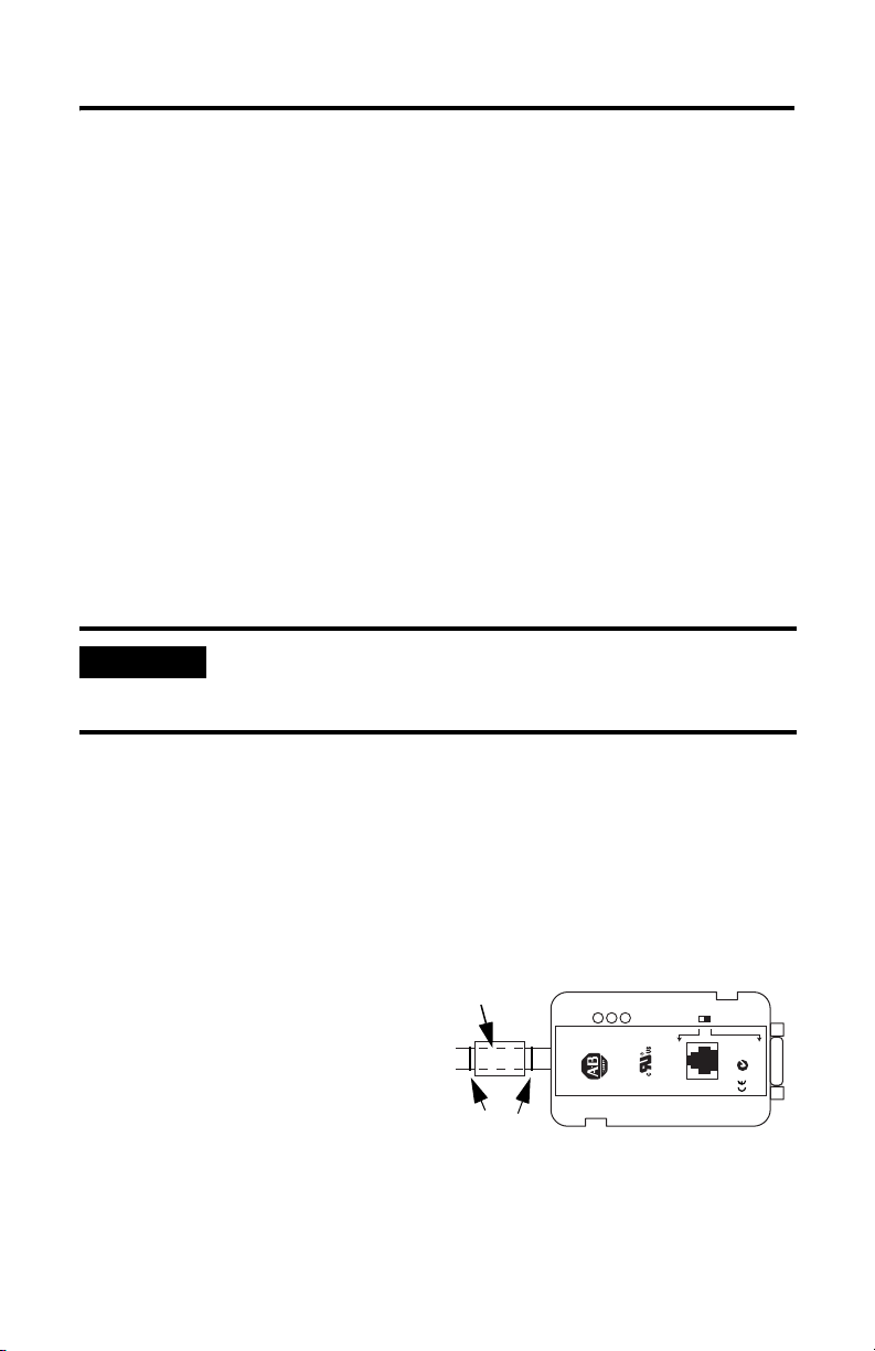
To be most effective, the ferrite collar must be placed between the cable ties on the
USB cable where the cable exits the 1747-UIC interface converter.
1. Fold the collar so that it encircles
the cable.
2. Press the plastic housing until
the collar snaps together.
3. Check that the collar is fully
latched.
ferrite collar
cable ties
USB (DF1)
CAT SER FRN
1747-UIC A X.X
OK
USB
USB to DH485
DH485
LISTED I.T.E.
INTERFACE CONVERTER
SW
RS485 (DH485)
MADE IN INDIA
Mfg
XXXX
N223
RS232 (DH485)
Publication 1747-IN063C-EN-P - January 2006
Page 5
Universal Serial Bus (USB) to DH-485 Interface Converter 5
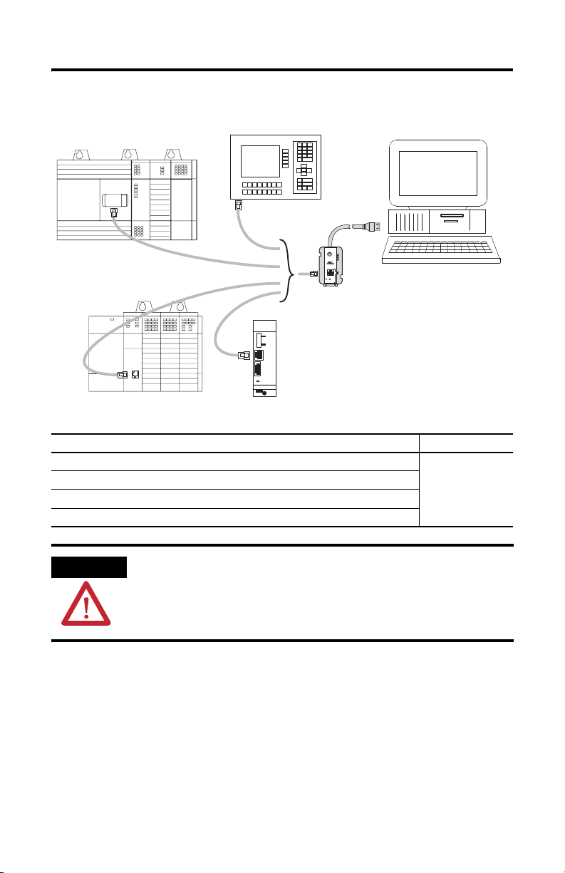
Connect DH-485 Devices to the Interface Converter’s RS-485 Port
SLC 500 Fixed Controller
Personal
Computer with
USB Port
PanelView 300
and Higher
Te rm in a l
DH-485
1747-AIC
Peripheral
CPU
Power
SLC 5/01, SLC 5/02, and SLC
5/03 (Channel 1) Controller
Connect the Following DH-485 Equipment to the RS-485 Port Use Cable
SLC 500 Fixed Controller
SLC 5/01, SLC 5/02, and SLC 5/03 (Channel 1) Controllers
1747-AIC Isolated Link Coupler
PanelView 300 and higher Terminals with DH-485 Ports
USB (DF1)
CAT SER FRN
1747-UIC A X.X
USB
OK
USB to DH485
INTERFACE CONVERTER
DH485
LISTED I.T.E.
RS485 (DH485)
SW
MADE IN INDIA
Mfg
XXXX
N223
1747-UIC
1747-C13
ATTENTION
To avoid ESD damage to the 1747-UIC interface converter, always
connect it to the properly grounded DH-485 device or interface
prior to plugging the USB cable into the computer’s USB port.
Publication 1747-IN063C-EN-P - January 2006
Page 6

6 Universal Serial Bus (USB) to DH-485 Interface Converter
Connect DH-485 Devices to the Interface Converter’s RS-232 Port
SLC 5/03, SLC 5/04, and
SLC 5/05 (Channel 0) Controller
CompactLogix Controller
FlexLogix Controller
MicroLogix
Controller
Personal
Computer with
USB Port
ControlLogix
Controller
AIC+
PanelView 300 and higher Terminal
USB (DF1)
CAT SER FRN
1747-UIC A X.X
USB
OK
USB to DH485
INTERFACE CONVERTER
DH485
LISTED I.T.E.
1747-UIC
RS485 (DH485)
SW
MADE IN INDIA
Mfg
XXXX
N223
RS232 (DH485)
Connect the Following DH-485 Equipment to the RS-232 Port Use Cable
SLC 5/03, SLC 5/04, and SLC 5/05 (Channel 0)
(1)
Controllers
1747-CP3, 1756-CP3
1761-NET-AIC (AIC+) Advanced Interface Converter 1747-CP3, 1756-CP3 (Port 1, 9-pin D)
1761-CBL-PM02 (Port 2, 8-pin DIN)
PanelView 300 and higher Terminals with RS-232 (DH-485) Ports 2711-NC13 or equivalent
MicroLogix
(1)
Controllers
1761-CBL-PM02 or equivalent
PanelView 300 Micro (DH-485) Terminals
(1)
CompactLogix
FlexLogix
ControlLogix
(1)
Make sure your controller’s Channel 0 configuration is set to DH-485 prior to connecting the 1747-UIC interface converter to
Channel 0. The factory default is DF1.
ATTENTION
Controllers
(1)
Controllers
(1)
Controllers
To avoid ESD damage to the interface converter, always connect
the interface converter to the properly grounded DH-485 device
1747-CP3, 1756-CP3
1747-CP3, 1756-CP3
1747-CP3, 1756-CP3
or interface prior to plugging the USB cable into the computer’s
USB port.
Publication 1747-IN063C-EN-P - January 2006
Page 7

Universal Serial Bus (USB) to DH-485 Interface Converter 7
Install the Drivers
Before using the 1747-UIC, you must install drivers for both the 1747-UIC interface
converter and the USB serial port. To install the drivers:
1. If you have RSLinx version 2.42, or higher, the 1747-UIC drivers are included
on the RSLinx distribution CD. Otherwise, you may download them onto
your hard drive from the Allen-Bradley product support webpage
(http://www.ab.com/support/products/pccards.html).
2. Plug the interface converter into your PC’s USB port.
3. Verify that the OK LED indicator is on (solid).
The Found New Hardware screen shows the Allen-Bradley 1747-UIC.
TIP
4. The Found New Hardware Wizard appears. Click Next.
TIP
If the 1747-UIC screen (above) does not appear within 30
seconds after you plug the 1747-UIC interface converter into
the computer’s USB port, then either the computer has
already been configured for this interface converter, or
there is a problem with the USB port on the computer.
You can determine whether the computer was previously
configured for this interface converter by checking the
computer’s COM port assignments. See Identify the
Assigned COM Port on page 11.
The screens shown are from a Windows 2000 system.
Publication 1747-IN063C-EN-P - January 2006
Page 8

8 Universal Serial Bus (USB) to DH-485 Interface Converter
5. The Install Hardware Device Drivers screen appears with Search for a
suitable driver… selected as the default. Click Next.
6. When the Locate Driver Files screen appears, select the media where the
drivers are stored. Click Next.
7. When the wizard indicates that it has found the driver for the 1747-UIC
interface converter, click Next.
Publication 1747-IN063C-EN-P - January 2006
Page 9

Universal Serial Bus (USB) to DH-485 Interface Converter 9
8. Click Finish to complete the installation of the 1747-UIC interface converter.
If you have Windows98/ME, your installation completes automatically and
you may proceed directly to Identify the Assigned COM Port on page 11.
Otherwise, continue with step 9.
9. The Found New Hardware Wizard continues immediately with installation of
the USB serial port. Click Next.
10. The Install Hardware Device Drivers screen appears with Search for a
suitable driver… selected as the default. Click Next.
Publication 1747-IN063C-EN-P - January 2006
Page 10

10 Universal Serial Bus (USB) to DH-485 Interface Converter
11. When the Locate Driver Files screen appears, select Specify a location,
Floppy disk drives, or CD-ROM drives, and click Next.
12. When the wizard indicates that it has found the driver for the USB Serial
Port, click Next.
13. Click Finish to complete the installation of the USB Serial Port.
Publication 1747-IN063C-EN-P - January 2006
Page 11

Universal Serial Bus (USB) to DH-485 Interface Converter 11
Identify the Assigned COM Port
Identify the assigned COM port using Device Manager, as shown below.
Windows Version Required Steps
Windows 98/ME 1. From the Start menu, choose Settings>Control Panel>System.
Windows 2000 1. From the Start menu, choose Settings>Control Panel>System.
Windows XP 1. From the Start menu, choose Control Panel>Performance and
2. From the System Properties Window, select the Device Manager tab.
3. Select the View devices by type radio button.
2. From the System window, choose the Hardware tab and click the Device
Manager button.
3. From the Device Manager, choose View>Devices by Type.
Maintenance>System Properties.
2. From the System window, select the Hardware tab and click the Device
Manager button.
3. From the Device Manager, choose View>Devices by Type.
TIP
The 1747-UIC interface converter will only appear under
Device Manager when the converter is plugged into the
computer’s USB port, with the OK LED indicator on (solid),
and when the 1747-UIC drivers are installed.
If the drivers have not yet been installed, see Install the Drivers
on page 7.
Example Using Windows 2000
Configure the 1747-UIC Interface Converter in RSLinx
1. Launch RSLinx.
2. Choose Configure Drivers from the Communications menu.
Publication 1747-IN063C-EN-P - January 2006
Page 12

12 Universal Serial Bus (USB) to DH-485 Interface Converter
3. Choose RS-232 DF1 devices from the Available Driver Types pulldown menu
and click Add New…
4. Enter a name for your new driver and click OK.
5. Choose the COM Port to which the interface converter is associated, in this
case COM 3.
TIP
You can determine the COM port to which the interface
converter is assigned using the Device Manager.
See Identify the Assigned COM Port on page 11.
6. Choose 1770-KF3/1747-KE as the Device.
7. Set Error Checking to CRC. The default is BCC.
Publication 1747-IN063C-EN-P - January 2006
Page 13

Universal Serial Bus (USB) to DH-485 Interface Converter 13
8. The 1747-UIC interface converter operates at 19.2 Kbps only, so set the Baud
Rate to 19200.
Do not click AutoConfigure.
9. Assign the 1747-UIC interface converter an unused station number on the
DH-485 network to which you are connecting.
The interface converter cannot go online to a DH-485 network if it’s
assigned station number is already being used. Station number 0 is typically
reserved for use by RSLinx, but any station number from 0 to 31 is valid.
10. Click OK.
The 1747-UIC interface converter appears on the network at node 0, as
shown in the example below.
IMPORTANT
Always stop the RSLinx RS-232 DF1 driver or shut down
RSLinx prior to unplugging the interface converter from the
computer’s USB port.
Uninstall the Drivers
To uninstall the 1747-UIC drivers from a computer:
1. Choose Add/Remove Programs from the Windows Control Panel.
2. Select FTDI USB Serial Converter Drivers.
Publication 1747-IN063C-EN-P - January 2006
Page 14

14 Universal Serial Bus (USB) to DH-485 Interface Converter
USB
OK
DH485
FRN
X.X
3. Click Change/Remove and follow the instructions.
4. Click Continue and then click Finish.
Change the Station Number
If you want to change the station number when the 1747-UIC interface converter is
already online to a DH-485 network with an existing station number, you must:
1. Configure the new station number in the RSLinx DF1 driver.
2. Stop the RSLinx DF1 driver.
3. Unplug the 1747-UIC interface converter from the computer’s USB port.
4. Plug the interface converter back into the computer’s USB port.
5. Start the RSLinx DF1 driver.
Now, when you go online through the 1747-UIC interface converter, it will use the
new station number.
Interpret the LED Indicators
The interface converter has three green LED indicators, which indicate the
following when lit:
USB (DF1)
CAT SER FRN
1747-UIC A X.X
USB
OK
USB to DH485
INTERFACE CONVERTER
DH485
LISTED I.T.E.
RS485 (DH485)
SW
MADE IN INDIA
Mfg
XXXX
N223
RS232 (DH485)
Publication 1747-IN063C-EN-P - January 2006
LED Indicator Description
OK (solid) The USB port is powered and operational.
USB (flashing) The USB port is transmitting or receiving
DF1 data.
DH-485 (flashing) The interface converter is actively passing
token or data on DH-485 network.
Page 15

Universal Serial Bus (USB) to DH-485 Interface Converter 15
If the LED
Indicators Show
• All LEDs off No power to
• OK LED on solid
• USB LED off
• DH-485 LED off
• OK LED on solid
• USB LED
flashing
• DH-485 LED off
• OK LED on solid
• USB LED
flashing
• DH-485 LED
flashing
The Following
Error Exists
1747-UIC
No
communication
occurring
through USB or
DH-485 ports
No DH-485
communication
s
RSWho doesn’t
display any
devices on the
DH-485 network
other than the
1747-UIC
Probable
Cause
No power from
USB port
RSLinx is not yet
attempting to
communicate
through the
1747-UIC
interface
converter
Duplicate sta tion
address
Improper
connection to
DH-485 network
or improper
configuration of
RSLinx RS-232
DF1 driver
Recommended Action
1. Check cable connection to computer’s USB port.
2. Verify power to the computer and it’s USB port.
3. Plug the interface converter into a different
computer’s USB port to verify the condition of the
interface converter.
1. Check which COM port the interface converter is
configured for.
See Identify the Assigned COM Port on page 11.
2. Verify that the RSLinx RS-232 DF1 driver is
assigned to this COM port, is configured properly,
and is running.
Examples: See page 12 for proper configuration
and page 13 for the Configure Drivers dialog that
shows that the driver is running.
1. Verify the existing station addresses on the
DH-485 network and make sure that the RSLinx
RS-232 DF1 driver is assigned to an unused
station address in the 0 to 31 range.
1. Verify that the SW switch is in the correct
position for the DH-485 connector being used.
2. Verify that the correct cable is being used.
See Connect DH-485 Devices to the Interface
Converter’s RS-485 Port on page 5.
3. Verify that the Device type in the RS-232 DF1
driver configuration is 1770-KF3/1747-KE so that
RSWho will browse stations 0 through 31.
Specifications
Universal Serial Bus to DH-485 Interface Converter - 1747-UIC
Attribute Value
Dimensions (HxWxD), Approx. 80.8 x 46.5 x 24.5 mm (3.18 x 1.83 x 0.97 in.)
Dimensions with DIN Rail Mounting
Hardware (HxWxD), Approx.
Mounting Hole Center-to-Center Spacing 39.3 mm (1.55 in) and 86.9 mm (3.42 in.)
Temperature Range 0…60 °C (32…140 °F)
USB Speed USB 1.1 (12 Mbps)
USB Power Consumption < 100 mA (low power)
DH-485 Baud Rate 19.2 Kbps only
109 x 50.6 x 31 mm (4.29 x 1.99 x 1.22 in.)
Publication 1747-IN063C-EN-P - January 2006
Page 16

Rockwell Automation Support
Rockwell Automation provides technical information on the web to assist you in
using its products. At http://support.rockwellautomation.com, you can find
technical manuals, a knowledge base of FAQs, technical and application notes,
sample code and links to software service packs, and a MySupport feature that you
can customize to make the best use of these tools.
For an additional level of technical phone support for installation, configuration and
troubleshooting, we offer TechConnect Support programs. For more information,
contact your local distributor or Rockwell Automation representative, or visit
http://support.rockwellautomation.com.
Installation Assistance
If you experience a problem with a hardware module within the first 24 hours of
installation, please review the information that's contained in this manual. You can
also contact a special Customer Support number for initial help in getting your
module up and running:
United States 1.440.646.3223
Outside United
States
New Product Satisfaction Return
Rockwell tests all of its products to ensure that they are fully operational when
shipped from the manufacturing facility. However, if your product is not
functioning and needs to be returned:
United States Contact your distributor. You must provide a Customer Support case number
Outside United
States
Monday – Friday, 8am – 5pm EST
Please contact your local Rockwell Automation representative for any
technical support issues.
(see phone number above to obtain one) to your distributor in order to
complete the return process.
Please contact your local Rockwell Automation representative for return
procedure.
Allen-Bradley, SLC, CompactLogix, ControlLogix, FlexLogix, MicroLogix, PanelView, and RSLinx are trademarks of Rockwell
Automation. Trademarks not belonging to Rockwell Automation are the property of their respective companies.
Publication 1747-IN063C-EN-P - January 2006 PN 40071-155-01(3)
Supersedes Pub lication 1747-IN063B-EN -P - September 2003 Copyright © 20 06 Rockwell Automati on, Inc. All rights reser ved. Printed in the U.S.A.
 Loading...