

Page 1
User Manual
Bulletin 1608N MiniDySC® Dynamic Sag Corrector
Single Phase Voltage Sag Correction 2...6 Amps (250...750 VA)
Page 2
Important User Information
IMPORTANT
Solid-state equipment has operational characteristics differing from those of electromechanical equipment. Safety Guidelines for the
Application, Installation and Maintenance of Solid State Controls (publication SGI-1.1
Automation sales office or online at http://www.rockwellautomation.com/literature/
solid-state equipment and hard-wired electromechanical devices. Because of this difference, and also because of the wide variety of uses
for solid-state equipment, all persons responsible for applying this equipment must satisfy themselves that each intended application of
this equipment is acceptable.
In no event will Rockwell Automation, Inc. be responsible or liable for indirect or consequential damages resulting from the use or
application of this equipment.
The examples and diagrams in this manual are included solely for illustrative purposes. Because of the many variables and requirements
associated with any particular installation, Rockwell Automation, Inc. cannot assume responsibility or liability for actual use based on
the examples and diagrams.
No patent liability is assumed by Rockwell Automation, Inc. with respect to use of information, circuits, equipment, or software
described in this manual.
Reproduction of the contents of this manual, in whole or in part, without written permission of Rockwell Automation, Inc., is
prohibited.
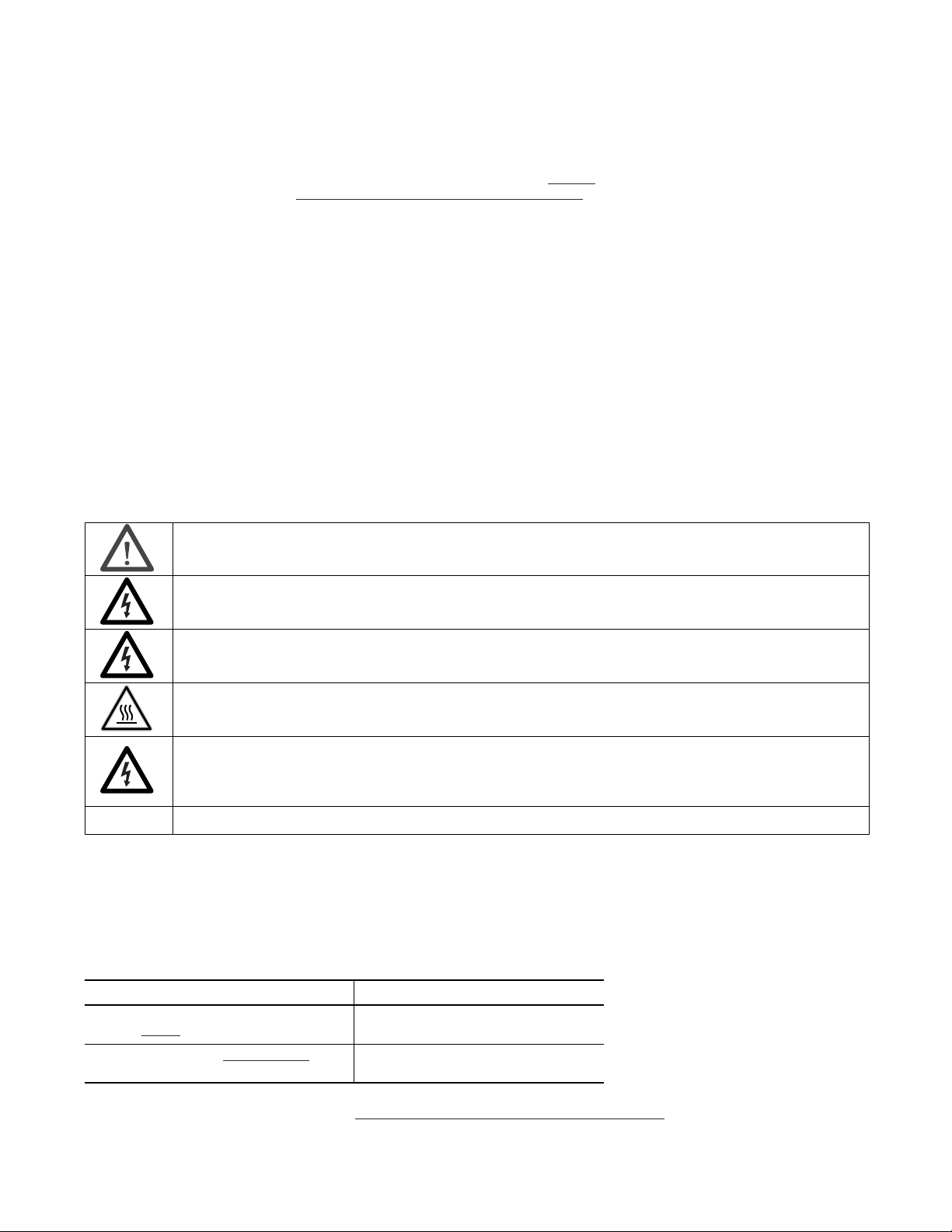
Throughout this manual, when necessary, we use notes to make you aware of safety considerations.
WARNING: Identifies information about practices or circumstances that can cause an explosion in a hazardous environment or
which may lead to personal injury or death, property damage, or economic loss.
available from your local Rockwell
) describes some important differences between
ATTENTION: Identifies information about practices or circumstances that can lead to personal injury or death, property
damage, or economic loss. Attentions help you identify a hazard, avoid a hazard, and recognize the consequence.
SHOCK HAZARD: Labels may be on or inside the equipment, for example, a drive or motor, to alert people that dangerous
voltage may be present.
BURN HAZARD: Labels may be on or inside the equipment, for example, a drive or motor, to alert people that surfaces may
reach dangerous temperatures.
ARC FLASH HAZARD: Labels may be on or inside the equipment, for example, a motor control center, to alert people to
potential Arc Flash. Arc Flash will cause severe injury or death. Wear proper Personal Protective Equipment (PPE). Follow ALL
Regulatory requirements for safe work practices and for Personal Protective Equipment (PPE).
Identifies information that is critical for successful application and understanding of the product.
MiniDySC, Allen-Bradley, Rockwell Software, Rockwell Automation, and TechConnect are trademarks of Rockwell Automation, Inc. Trademarks not belonging to Rockwell Automation are property of their respective
companies.
Additional Resources
These documents contain additional information concerning related products from Rockwell Automation.
Resource Description
Industrial Automation Wiring and Grounding Guidelines,
publication 1770-4.1
Product Certifications website, http://www.ab.com
Provides general guidelines for installing a Rockwell
Automation industrial system.
Provides declarations of conformity, certificates, and
other certification details.
You can view or download publications at http:/www.rockwellautomation.com/literature/
. To order paper copies of
technical documentation, contact your local Allen-Bradley distributor or Rockwell Automation sales representative.
Page 3

Table of Contents
Important User Information . . . . . . . . . . . . . . . . . . . . . . . . . . . . . . . . . . . . . . . . 2
Additional Resources . . . . . . . . . . . . . . . . . . . . . . . . . . . . . . . . . . . . . . . . . . . . . . . 2
Ch 1 - Installation
Ch 2-Operation
Installation Check List . . . . . . . . . . . . . . . . . . . . . . . . . . . . . . . . . . . . . . . . . . . . . 5
Inspecting and Unpacking . . . . . . . . . . . . . . . . . . . . . . . . . . . . . . . . . . . . . . . . . . 5
Location (Environment). . . . . . . . . . . . . . . . . . . . . . . . . . . . . . . . . . . . . . . . . . . . 5
Mounting Instructions . . . . . . . . . . . . . . . . . . . . . . . . . . . . . . . . . . . . . . . . . . . . . 6
DIN Rail Mount . . . . . . . . . . . . . . . . . . . . . . . . . . . . . . . . . . . . . . . . . . . . . . . 6
Panel Mount. . . . . . . . . . . . . . . . . . . . . . . . . . . . . . . . . . . . . . . . . . . . . . . . . . . 6
Ground Connection . . . . . . . . . . . . . . . . . . . . . . . . . . . . . . . . . . . . . . . . . . . . . . . 7
Power Connections . . . . . . . . . . . . . . . . . . . . . . . . . . . . . . . . . . . . . . . . . . . . . . . . 7
Line Connections (Input). . . . . . . . . . . . . . . . . . . . . . . . . . . . . . . . . . . . . . . 7
Load Connections (Output) . . . . . . . . . . . . . . . . . . . . . . . . . . . . . . . . . . . . 7
Connection Diagrams . . . . . . . . . . . . . . . . . . . . . . . . . . . . . . . . . . . . . . . . . . . . . . 8
Alarm Contact Connections . . . . . . . . . . . . . . . . . . . . . . . . . . . . . . . . . . . . . . . . 9
Power Switch . . . . . . . . . . . . . . . . . . . . . . . . . . . . . . . . . . . . . . . . . . . . . . . . . . . . . . 9
Operating Indicators . . . . . . . . . . . . . . . . . . . . . . . . . . . . . . . . . . . . . . . . . . . . . . . 9
Alarm Codes . . . . . . . . . . . . . . . . . . . . . . . . . . . . . . . . . . . . . . . . . . . . . . . . . . . . 10
Alarm LED Flash Sequence . . . . . . . . . . . . . . . . . . . . . . . . . . . . . . . . . . . 10
Ch 3-Specifications and Dimensions
Technical Specifications . . . . . . . . . . . . . . . . . . . . . . . . . . . . . . . . . . . . . . . . . . 11
Approximate Dimensions. . . . . . . . . . . . . . . . . . . . . . . . . . . . . . . . . . . . . . . . . 12
Rockwell Automation Publication 1608N-UM001B-EN-P - May 2014 3
Page 4

Table of Contents
Notes:
4 Rockwell Automation Publication 1608N-UM001B-EN-P - May 2014
Page 5
Installation
Chapter 1
Installation Check List
ATTENTION: Dangerous voltages will be present on the MiniDySC terminal block while in service. The MiniDySC is intended
for use as a component of complete equipment and should not be separately installed in the field. The user must assure a
safe operating environment.
ATTENTION: Metallic contamination inside the MiniDySC enclosure will void the warranty.
Before proceeding, please take a few minutes to review the necessary steps:
• All packing materials and restraints have been removed
• All cables are properly routed
• All power cables are properly terminated
• Properly installed ground connector
• Properly terminated neutral connection (if required)
• Clean, dust-free work space with adequate lighting
• Mount the MiniDySC in an upright orientation with at least 2” (50 mm)
clearance above and below for proper cooling- see Figure 1
• Take care to prevent metallic particles from entering the vent holes
• Operational checks have been reviewed and completed
• The MiniDySC may be DIN rail or panel mounted within an enclosure as
long as the ambient temperature remains at or below 40 °C
and Figure 2.
Inspecting and Unpacking
Location (Environment)
• Carefully inspect the outer packaging for evidence of damage during
transit. Do not install a damaged cabinet. Report any damage to the carrier
and contact your local sales or service immediately.
• Check the MiniDySC label for correct model number with the packaging
list to ensure you have received the correct voltage, current, and wiring
configurations.
• After removing the packaging material, inspect the contents for any
evidence of physical damage, and compare each item with the Bill of
Lading. If damage has occurred or shortages are evident contact your
carrier immediately.
NOTICE: Install this equipment in an indoor temperature-controlled area, free from
condensation and conductive contaminants such as carbon dust.
The MiniDySC must be installed in a protected environment. The location must
provide adequate airflow around the MiniDySC in an atmosphere free from
excessive dust, corrosive fumes, or conductive contaminants. Do not operate the
MiniDySC in an environment where the ambient temperature or humidity is
beyond the specified limits given in this manual.
Rockwell Automation Publication 1608N-UM001B-EN-P - May 2014 5
Page 6

Chapter 1 Installation
Mounting Instructions
DIN Rail Mount
Figure 1 - DIN Rail Mounting 1. Mount on a 35 x 7.5 mm DIN rail that conforms to the EN 50022
standard.
2. The DIN mounting clips come pre-assembled to the back of the unit.
3. Hook the top edge of the mounting clips over the top flange of the
DIN rail.
4. Pivot the MiniDySC down until the unit latches to the DIN rail.
5. To secure the MiniDySC to the DIN rail assemble the locking clip to the
top of the MiniDySC with one (1) of the #6 sheet metal screws supplied.
See Figure 1
6. An alternative method to using the locking clip to secure the MiniDySC to
the DIN rail is to use the lower panel-mounting bracket. Prior to mounting
the unit to the DIN rail install the lower panel-mounting bracket as
outlined under “Panel mounting instructions”. Once the unit is latched to
the DIN rail the unit can be secured to the mounting panel with a screw as
described under the panel mounting instructions.
.
Panel Mount
Figure 2 - Panel Mounting 1. The MiniDySC may be panel mounted with the supplied hardware.
2. Do not remove the DIN mounting clips.
3. Attach the two (2) panel mounting brackets to the MiniDySC with four
(4) #6 sheet metal screws supplied. See Figure 2
4. The panel mounting brackets were designed to accept #8 - #10 hardware
with a maximum head diameter of 0.375" (9.5 mm).
5. The center-to-center vertical mounting dimension for screw location is
8.65" (220 mm) on the 250 VA rated MiniDySC models and 9.65" (245
mm) on the 500 VA and 750 VA rated models.
.
6 Rockwell Automation Publication 1608N-UM001B-EN-P - May 2014
Page 7

Operation
Chapter 2
Ground Connection
Power Connections
• Connect the safety ground (earth) conductor to the #8-32 (4.2mm dia.)
ground stud (Refer to Figure 3 on page 8
• Torque to 20 lb-in (2.3 N-m)
Note: The MiniDySC must be safety grounded according to the National Electrical Code. All local, state, and
federal regulations applicable to the installation of electrical systems apply.
• First remove the 6-pin terminal block connector by removing two retaining
screws and pulling out. After connections are made reinstall terminal block
connector by pressing back in place and tightening the two retaining screws.
• Wire Size: 26 - 12 AWG (0.13 - 3.31 mm
• Wire Strip Length: 0.256" (6.5 mm)
• To rq u e : 5 lb -in (0.6 N-m)
or Figure 4 on page 8).
2
)
Line Connections (Input)
• For Line-Neutral MiniD ySC (part numbers ending in V2S or V2E): connect
utility L1 (hot) and N (neutral) to terminals labeled L1 (pin 5) and N (pin
6) as shown in Figure 3 on page 8
• For Line-to-Line MiniDySC (part numbers ending in V1S or V1E): connect
utility L1 and L2 to terminals labeled L1 (pin 5) and L2/X2 (pin 6) as
shown in Figure 4 on page 8
.
.
Load Connections (Output)
• For Line-Neutral MiniD ySC (part numbers ending in V2S or V2E): connect
load wires to terminals labeled X1 (pin 4) and N (pin 6) as shown in Figure 3
on page 8.
• For Line-to-Line MiniDySC (part numbers ending in V1S or V1E): connect
load wires to terminals labeled X1 (pin 4) and L2/X2 (pin 6) as shown in
Figure 4 on page 8
Rockwell Automation Publication 1608N-UM001B-EN-P - May 2014 7
.
Page 8

Chapter 2 Operation
C NC NO X1 L1 N
Input A.C.
SW1 F1
1 2
Ground
L1
Neutral
Neutral
Ground
X1
LOADLOAD
C NC NO X1 L1 L2/X2
Input A.C.
SW1 F1
1 2
Ground
L1
L2/X2
Ground
X1
LOADLOAD
F2
2
L2/X2
Connection Diagrams
Figure 3 - 120, 220,230, 240 Volt, 1 Phase, Line-to-Neutral Connection Diagram
1. User-supplied service disconnect (SW1). MiniDySC must be supplied through a
single pole switch in the "hot" line, with voltage and current ratings greater than or
equal to the MiniDySC ratings.
2. User-supplied fuse (F1). AC input must be fused. See Ta b l e 1
for recommended
fuse.
Note: Input neutral must be connected for all 120V, 220V and 230V applications. Failure to do so may result in
damage to the MiniDySC. Do not connect to a source with an AIC rating greater than 10,000 Arms.
Table 1 - Fuse Rating
MiniDySC Rating 250 VA 500 VA 750 VA
120V 6A,120V 15A, 120V 15A, 120V
220...240V 3.2A, 250V 10A, 250V 10A, 250V
Recommended Fuses: Bussmann MDA-6 Bussmann FRN-R-15 Bussmann FRN-R-3-2/10
Bussmann FRN-R-10
Figure 4 - 208 & 240 Volt, 1 Phase, Line-to-Line Connection Diagram
1. User-supplied service disconnect (SW1). MiniDySC must be supplied through a
double-pole switch located in both "hot" lines, with voltage and current ratings
greater than or equal to the MiniDySC ratings
2. User-supplied fuses (F1, F2). Both hot lines of the AC input must be fused.
SeeTa b l e 2
for recommended fuse.
Note: Do not connect to a source with an AIC rating greater than 10,000 Arms
Table 2 - Fuse Rating
8 Rockwell Automation Publication 1608N-UM001B-EN-P - May 2014
MiniDySC Rating 250 VA 500 VA 750 VA
208..240V 3.2A, 250V 10A, 250V 10A, 250V
Recommended Fuses: Bussmann FRN-R-3-2/10 Bussmann FRN-R-10
Page 9

Operation Chapter 2
2
1
NO
NC
COM
120 VAC .5 A
Alarm Rel ay Rating
3
30 VDC 1A
Alarm Contact Connections
Power Switch
Operating Indicators
• The alarm contact will change states during any alarm condition. When the
alarm condition has cleared, the alarm relay will return to its normal state.
• Terminal block pin numbers and Alarm contact ratings are shown in Figure 5
Operation is as follows:
– Normal Line Condition: pin 1 connects to pin 3.
– Alarm Condition: pin 1 connects to pin 2.
– Power Off Condition: pin 1 connects to pin 2.
Figure 5 - Alarm Contact
The service disconnect or the external branch circuit breaker may be used as a
master on/off switch.
• When power is switched on, the Green light (Normal) on the front of the
MiniDySC will be lighted. The green light indicates that the output voltage
is within a normal range of -13% to +10% of nominal. This indicator will
also be on during sag correction events since the MiniDySC will be
maintaining the output voltage.
• The Amber light (Alarm) flashes when the MiniDySC correction function
is inhibited. See Alarm Codes section below. The MiniDySC will resume its
corrective function and the flashing light will turn off when the alarm
condition has ceased. In a flashing amber light condition, the MiniDySC
will continue to pass the utility power to the load via the static switch.
• The Red light will be on when the Static switch is inhibited due to an
overload condition. The MiniDySC will open the output. Power will need to
be cycled to reset the MiniDySC.
Table 3 - List of conditions and indications
Condition Description Red
Light
Status
Normal 88.5% < VLINE < 110% of Nominal Off On Off Off
Sag Event VLINE < 88.5% while MiniDySC is correcting
Runtime Exceeded Cumulative runtime exceeded
Normal Mode, Static Switch Overload Continuous Load current > 150% On Off Off Inhibited
Inverter Run Mode, Output Over current Load current > 150% for 3 cycles Off On
Refer to Run Time specifications in Technical Specifications on page 11
See Static Switch Maximum Current specifications in Technical Specifications on page 11
If red LED is on, the output of the MiniDySC is inhibited and power needs to be cycled. If the problem reoccurs, the MiniDySC is overloaded.
On, provided output is within normal range 88.5%< VLINE <110%.
Check Alarm Codes
Rockwell Automation Publication 1608N-UM001B-EN-P - May 2014 9
Off On Flashing Inhibited
Off On Off Running
Green
Light
Status
Flashing Inhibited
Amber
Light
Status
Inverter
Operation
Status
Page 10

Chapter 2 Operation
Alarm Codes
Alarm LED Flash Sequence
While the MiniDySC is in the alarm state due to a non-fatal alarm, the amber
LED will flash the alarm code sequence at 1Hz where the number of flashes
equals the alarm code. There is a two-second delay, after which the code will
repeat if the error condition persists. This group of alarms are those that the user
can act to correct, such as an overload or input over-voltage.
Some alarms cannot be corrected by user action. These alarms may require service
by a qualified technician. For such alarms the amber LED will flash continuously
at a faster 6 Hz rate.
Table 4 - Alarm LED Flash Descriptions
Alarm Name Number
of Flashes
Inverter Run Time out
Inverter Limit Cycle Timeout Power was re-applied more than once within a 58 second period. No action is needed
Overload
Static Switch Over -Temperature Static switch heatsink temperature was greater than maximum rating.
DC Bus Over-Voltage 5 Positive or negative half of DC bus voltage exceeded maximum rating.
Alarm Description Alarm Resolution
MiniDySC inverter had a total cumulative runtime of more than rated. No action is needed
3
Inverter inhibited because load current exceeded maximum rating. Reduce the load
4
• Verify ambient temperature is within specification
• Check for dirty or obstructed air vents
• Check fan is operating (500VA and 750VA only)
• Verify line voltage is within ratings.
• Verify proper MiniDySC application
• Call Ser vice
10 Rockwell Automation Publication 1608N-UM001B-EN-P - May 2014
Page 11

Specifications and Dimensions
Technical Specifications
Table 5 - Technical Specifications – MiniDySC (2...6 Amps)
Electrical Input/Output (No rmal Mode—Static Switch)
Connection Configuration Series-connected with load. Under normal line condition, the static switch passes utility voltage directly to the load
Standard Input Voltage DySC 1Phase: 120, 208, 220, 230, 240V
Voltage Range ±10%
Current Overload
(Trip above these levels)
Frequenc y 50/60 Hz Auto Sensing
Frequency RangeUSBDLJOH 45 t
Surge Protect
Efficiency 250 VA > 94%, 500 VA > 97%, 75 0 VA > 96%
Phase (wiring) 1 phase (L-L & L-N)
Detection Voltage 88.5% of rated voltage
Response Time (typical) 0.7 ms detection, 1.2 ms inverter reaction (<2ms)
Output Voltage Matches pre-sag input voltage
Voltage Regulation ±5% typical, +5% / -13% of nominal max
Output Current Rated RMS (2A ... 6A) with 300 % instantaneous peak max
Crest Factor (at rated load) 3.0
Load Power factor range -0.5 ...+0.9, DC component <2% of rated current
Voltage Waveform (typical) Sine wave
87% to 50% voltage remaining 5 seconds SR & ER
Sags to zero voltage remaining 50ms or 200ms (standard or extended run time DySCs). Based on nameplate ratings with a power factor of 0.7
Max Sag Correction Time 5 seconds cumulative usage
Seqential Sag Recovery 0 seconds (assuming cumulative run-time available)
Full Recovery Time Max 5 minutes to full recover y
Enclosure Ratings NEMA 1 (IP20)
Cooling Forced air (500VA, 750VA) or natural convection (250VA)
Access Lower front for connections
Accessibility (W iring) Pluggable compression terminal block
Indicators 3 LEDs: Overload Trip, Normal, Alarm
Connectivity Form C contacts rated 120Vac@0.5A or 30Vdc@1A
Ambient Temperature 0 ...+50°C
Storage Temperature -40°C ...+75°C
Relative Humidity 0 ...95% non-condensing
Altitude Rated current available to 1000m (3300ft)
Agency Approvals cULus recognized, Exceeds SEMI F47 Standard
ion Device (SPD) Built-in 3-Layers consisting of MOVs & Capacitors
110% continuous, 150% @ 10 sec., 200% @ 0.5 sec., 300% @ 10 cycles, 400% @ 3 cycles, 1000% Instantaneous
o 65 Hz
Electrical Output (S ag Correction Mode—Inverter)
Voltage Sag Correction Times
Single Event
Multiple Events
Mechanical
Communications / User Interface
Environmental
Certifications
Chapter 3
Rockwell Automation Publication 1608N-UM001B-EN-P - May 2014 11
Page 12

Chapter 3 Specifications and Dimensions
5.8
146.6
ER
3.4
85.9
SR
"B"
.4
10.1
"A"
.3
6.4
SR/ER
Approximate Dimensions
Dimensions
Rating (VA) Dimensions - H x W x D in. [mm] Weight - lbs. [kg]
Standard Run-time (SR)
250 8.3 x 3.4 x 6 .3 [210.8 x 86.4 x 160] 4.8 [2.18]
500 9.3 x 3.4 x 7.8 [236.2 x 86.4 x 198.1] 6.3 [2.86]
750 9.3 x 3.4 x 7.8 [236.2 x 86.4 x 198.1] 6.7 [3.04]
Extended Run-time (ER)
250 8.3 x 5.8 x 6.3 [210.8 x 147.3 x 160] 8.0 [3.63]
500 9.3 x 5.8 x 7.8 [236.2 x 147.3 x 198.1] 9.5 [4.31]
750 9.3 x 5.8 x 7.8 [236.2 x 147.3 x 198.1] 10.2 [4.63]
Dimensions in inches [mm]. Dimensions are not intended to be used for manufacturing purposes.
Table 6 - Dimensi ons
Dimension
“A” 6.0 [152.4] 7.5 [190.5]
“B” 7.8 [197.7] 8.8 [223.1]
250 VA
in. [mm]
12 Rockwell Automation Publication 1608N-UM001B-EN-P - May 2014
500/750 VA
in. [mm]
Page 13

Page 14

Rockwell Automation Support
Rockwell Automation provides technical information on the Web to assist you in using its products.
At http://www.rockwellautomation.com/support
code and links to software service packs, and a MySupport feature that you can customize to make the best use of these
tools. You can also visit our Knowledgebase at http://www.rockwellautomation.com/knowledgebase
information, support chat and forums, software updates, and to sign up for product notification updates.
, you can find technical manuals, technical and application notes, sample
for FAQs, technical
For an additional level of technical phone support for installation, configuration, and troubleshooting, we offer
SM
Tech C o n nect
representative, or visit http://www.rockwellautomation.com/support/
support programs. For more information, contact your local distributor or Rockwell Automation
.
Installation Assistance
If you experience a problem within the first 24 hours of installation, review the information that is contained in this
manual. You can contact Customer Support for initial help in getting your product up and running.
United States or Canada 1.440.646.3434
Outside United States or Canada Use the Worl dwid e Loc ator
Rockwell Automation representative.
at http://www.rockwellautomation.com/rockwellautomation/support/overview.page, or contac t your local
New Product Satisfaction Return
Rockwell Automation tests all of its products to help ensure that they are fully operational when shipped from the
manufacturing facility. However, if your product is not functioning and needs to be returned, follow these procedures.
United States Contact your distributor. You must provide a Customer Support case number (call the phone number above to obtain one) to your
Outside United States Please contact your local Rockwell Automation representative for the return procedure.
distributor to complete the return process.
Documentation Feedback
Your comments will help us serve your documentation needs better. If you have any suggestions on how to improve this
document, complete this form, publication RA-DU002
Publication 1608N-UM001B-EN-P - May 2014 DIR #10000723452
Supersedes Publication 1608-UM001A-EN-P - July 2013 Copyright © 2014 Rockwell Automation, Inc. All rights reserved. Printed in the U.S.A
, available at http://www.rockwellautomation.com/literature/.
 Loading...