

Page 1

Reference Manual
1. Description
.........................................,............................. 1
2.
Specication Quick Reference ................................... 1
3.
Catalog Numbers ............................................................. 1
4. Certication Marks ........................................................... 1
5. Standby Mode ................................................................. 4
6. Charging Mode .............................................................. 4
7. Buer Mode ..................................................................... 5
8. Functional Diagram ...................................................... 6
9. Front Side and User Elements ................................ 6
10. Operating Diagram ...................................................... 7
11. Active and Ready Signal, Inhibit Input ............. 7
12.
Terminals and Wiring ................................................ 8
13. Reliability .................................................................... 8
14. EMC ................................................................................ 9
15. Environment ............................................................. 9
16. Protection Features ............................................ 10
17. Safety .......................................................................... 10
18. Certications
............................................................. 10
19. Physical Dimensions and Weight ............... 11
20. Wiring Diagrams .................................................. 12
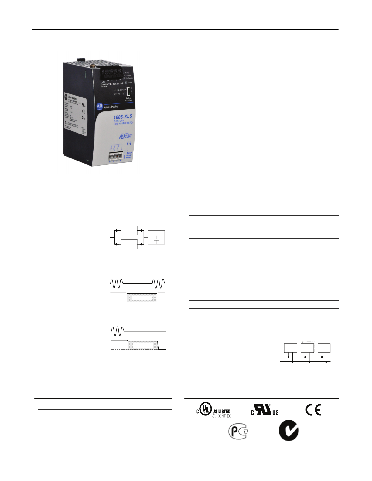
Bulletin 1606 Switched Mode Power Supplies
Catalog Number: 1606-XLSBUFFER24
Index
Installation Notes
Mounting Orientation—The power terminal shall be located on top of the unit.
Cooling—Convection cooled, no forced air cooling required. Do not obstruct air flow!
Recommended Installation Clearances—40mm on top of unit; 20mm on bottom of unit; 0mm (or 15mm if adjacent device is a heat source) on
the left and right sides of the unit.
Intended Use—This buffer unit is designed for use in panel board installations or other in-building applications where a suitable mechanical
enclosure is provided to fulfil local requirements.
Service Parts—This unit does not contain any service part. Should damage or malfunction occur during installation, turn power off immediately and
return unit to the manufacturer for inspection.
Page 2
Bulletin 1606 Switched Mode Power Supplies
Buer Unit
■
Buering with electrolytic capacitors instead
of lead batteries
■
Buering of 24V loads
■
Minimum hold-up time 0.2s at 20A
■
Longer hold-up time at lower loads
■
Clear status indication by status LED and signaling
terminals
■
Quick-connect spring-clamp terminals
■
3 year warranty
1. Description
2. Specication Quick Reference
Rated voltage DC 24V
Voltage range 24-28.8V
Output voltage 22.5V or
V
IN
–1V
selectable by
jumper
Output current 0 to 20A
Hold-up time
min 0.2s 22.5V, 20A
typ 0.31s 22.5V, 20A
min 28s 22.5V, 0.1A
typ 43s
22.5V, 0.1A
Charging current
max 600mA
Charging time
typ 18s
Input current typ 80mA standby mode
Power dissipation typ 1.9W standby mode
Temperature range
-25°C to +70°C operational
Dimensions 64x124x102mm WxHxD
The buer unit is a supplementary device for regulated
DC24V power supplies. It buers load currents during
typical mains faults and load peaks.
Working principle
In times when the power
supply provides sucient
voltages, the buer unit
stores energy in integrated electrolytic capacitors. In case of
mains voltage fault, this energy is released again in a
regulated process.
Bridges mains faults
without interruption
Statistic show that 80% of
all mains fault lasts less
than 0.2s. These mains
faults are completely bridged by the buer unit. This
increases the reliability of the system as a whole.
Extended hold-up time
Once mains power fails or
is switched o, the buer
unit will continue to
provide the load current
for a dened period of time. Process data can be saved and
processes can be terminated before the DC power switches
o. Controlled restarts are subsequently possible.
Easy to handle, expandable and maintenance-free
The buer unit does not require
any control wiring. It can be
added parallel to the load circuit
at any given point. Buer units
can be switched in parallel to
increase the output ampacity or the hold-up time.
DC
Charge
Discharge
Buffer
AC
DC
Buffer Unit
AC
DC
Buffer Unit
DC
Buffer
Unit(s)
Power
Supply
Load
AC
+
-
3. Catalog Numbers
4. Certication Marks
Buer Unit
1606-XLSBUFFER24
24, 20A, 200ms
Accessory 1606-XLB Wall mounting
bracket
UL 508
UL 60950-1
EMC, LVD
C-Tick
GOST R
2 Rockwell Automation Publication 1606-RM026A-EN-P — April 2014
All parameters are specified at 24V, 20A, 25°C ambient and after a 5 minutes run-in time, unless noted otherwise.
Page 3
Bulletin 1606 Switched Mode Power Supplies
Intended Use
• This device is designed for installation in an enclosure and is intended for the general professional use such as in industrial control, office,
communication, and instrumentation equipment.
• Do not use this power supply in aircraft, trains, nuclear equipment or similar systems where malfunction may cause severe personal injury or
threaten human life.
• This device is designed for use in non-hazardous, ordinary or unclassified locations.
Installation Requirements
• This device may only be installed and put into operation by qualified personnel.
• This device does not contain serviceable parts. The tripping of an internal fuse is caused by an internal defect.
• If damage or malfunction should occur during installation or operation, immediately turn power off and send unit to the factory for inspection.
• Mount the unit on a DIN rail so that the terminals are located on the bottom of the unit. For other mounting orientations, refer to Mounting.
• This device is designed for convection cooling and does not require an external fan. Do not obstruct airflow and do not cover ventilation grid
(e.g. cable conduits) by more than 30%!
• Keep the following installation clearances: 40mm on top, 20mm on the bottom, 0mm on the left and right sides are recommended when the
device is loaded permanently with more than 50% of the rated power. Increase this clearance to 15mm in case the adjacent device is a heat
source (e.g. another power supply).
SHOCK HAZARD: Do not use the power supply without proper grounding (Protective Earth). Use the terminal on the input
block for earth connection and not one of the screws on the housing.
- Turn power off before working on the device. Protect against inadvertent re-powering
- Make sure that the wiring is correct by following all local and national codes
- Do not modify or repair the unit
- Do not open the unit as high voltages are present inside
- Use caution to prevent any foreign objects from entering the housing
- Do not use in wet locations or in areas where moisture or condensation can be expected
- Do not touch during power-on, and immediately after power-off. Hot surfaces may cause burns.
WARNING: EXPLOSION HAZARDS!
Substitution of components may impair suitability for this environment. Do not disconnect the unit or operate the voltage adjustment or S/P jumper unless
power has been switched off or the area is known to be non-hazardous.
All parameters are specified at 24V, 20A, 25°C ambient and after a 5 minutes run-in time, unless noted otherwise.
Rockwell Automation Publication 1606-RM026A-EN-P — April 2014 3
Page 4
Bulletin 1606 Switched Mode Power Supplies
5. Standby Mode
Input voltage
nom. DC 24V
Voltage range
nom. 24-28.8Vdc
Input current
typ. 80mA Standby mode
Power dissipation typ. 1.9W
Status lamp
always on
Active signal
high ohmic
Ready signal
low ohmic
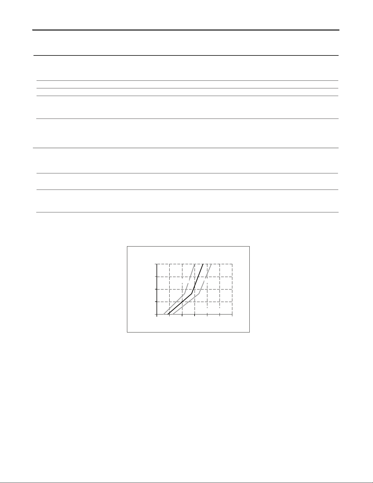
6. Charging Mode
Charging current
min. 0.4A Charging mode
max. 0.6A Charging mode
Charging time
min. 20s / 15s
Initial charge
1)
/ Re-charging
2)
max. 29s / 21s
Initial charge
1)
/ Re-charging
2)
Status lamp
ashes 1.25Hz
Active signal
high ohmic
Ready signal
high ohmic
1) Initial charging is the rst charge after voltage is applied to the buer unit.
2) Re-charging is the charging of the internal capacitors after voltage interruptions of less than 2 minutes.
Fig. 6-1 Re-charging time, 24V
Charge
20
0510 30s
Charging Time
40
80
60
100%
15 20 25
m
a
x
m
i
n
4 Rockwell Automation Publication 1606-RM026A-EN-P — April 2014
All parameters are specified at 24V, 20A, 25°C ambient and after a 5 minutes run-in time, unless noted otherwise.
Page 5
Bulletin 1606 Switched Mode Power Supplies
7. Buer Mode
Rated output current nom. 20A
Current limitation min. 20A Electronically limited
Output voltage typ. 22.5V Jumper in position “22.5V xed”
typ.
1V below input
voltage
Jumper in position “Vin –1V”
Ripple and noise voltage max. 200mVpp 20Hz to 20MHz, 50Ohm
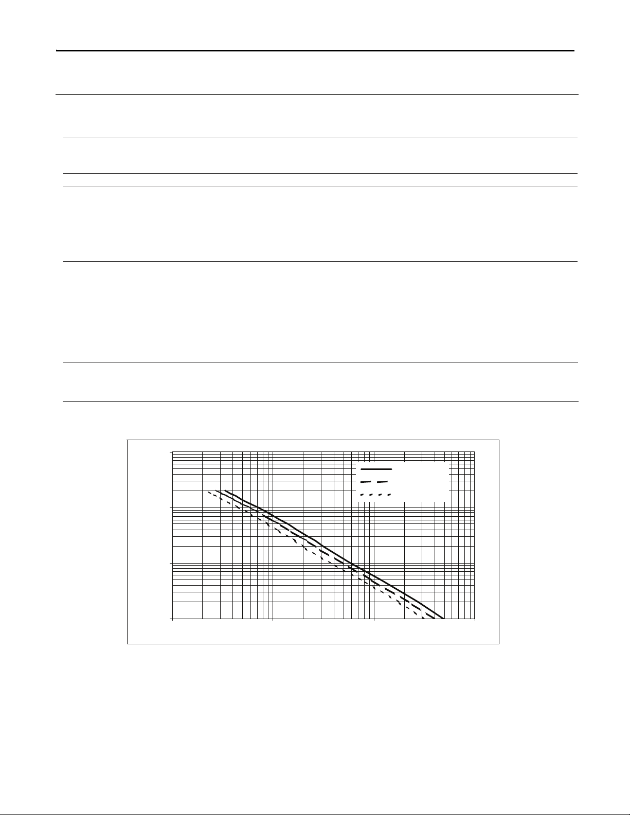
Hold-up time min. 0.2s 22.5V, 20A
typ. 0.31s 22.5V, 20A
min. 28s 22.5V, 0.1A
typ. 43s 22.5V, 0.1A
To increase buer current or extend hold-up time, any given number of buer
units can be installed in parallel.
Activation threshold typ. 22.5V
Ju
mper in position “22.5V xed”
Buering starts if terminal voltage falls below 22.5V.
typ. Vin –1V Jumper in position “Vin –1V”
Buering starts if the terminal voltage decreases by
more than 1V. Buering ends when terminal voltage
increases by more than 1V
Voltage changes slower than 0.54V/s will be ignored
unless the voltage is above 22.5V. Below 22.5V
buering starts immediately.
Status lamp
ashes 10Hz
Active signal
low ohmic
Ready signal
high ohmic
Fig. 7-1 Hold-up time
0,1 A
1,0 A
10,0 A
100,0 A
0,1 s 1,0 s 10,0 s 100,0 s
Buffer
Curr ent
typ. ( 22,5 V )
typ. ( 27,8 V )
min . ( 22 ,5 V )
All parameters are specified at 24V, 20A, 25°C ambient and after a 5 minutes run-in time, unless noted otherwise.
Rockwell Automation Publication 1606-RM026A-EN-P — April 2014 5
Page 6
Bulletin 1606 Switched Mode Power Supplies
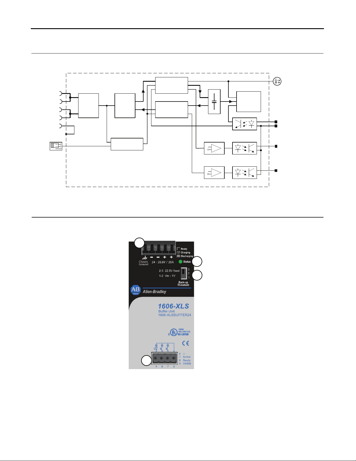
8. Functional Diagram
Fig. 8-1 Functional diagram
Buffer Capacitor
Charger &
Inrush Limiter
Buffer
Capacitor
Buffer Capacitor
Discharger
Status
lamp
7 Active
6 +
Ready Monitor
+
-
Active Monitor
+
-
Optokoppler
Optokoppler
8 Ready
9 Inhibit
Optokoppler
Buffer
Capacitor
Shut-Down
Input / Output
Voltage Monitor
Back-up
Level
Selector
Reverse-
Polarity
Protection
-
-
+
+
Safety and
Over-
Voltage
Protection
Chassis
Ground
9. Front Side and User Elements
Fig. 9-1 Front side
A. I/O Power Port
Quick-connect spring-clamp
terminals,
+ Positive terminal
- Negative terminal
Chassis Ground
to bond the housing
B. Status lamp
OFF: Buer is discharged, or
terminal voltage is below 22V
ON: Unit is fully charged
Flashes 1,25Hz:
Unit is in charging mode
Flashes 10Hz:
Unit is in discharging mode
C. Signal Port
Plug Connector
6 common + pole
7 Active : unit is buering
8
Ready : unit is on stand-by
9
Inhibit : initiates buer
discharging and inhibits
recharging of capacitors
D. Back-up threshold jumper
1-2: Variable mode
Unit switches to buer mode when input
voltage decreases by 1V within 0.54V/s or
the input voltage falls below 22.5V.
2-3: Fixed mode, (factory setting)
Unit switches to buer mode as soon as the
voltage falls below 22.5V
Missing jumper = 22.5V xed
Set the unit to xed mode:
- when using other power supplies
than the 1606-XLS series
- with back-feeding loads
- when the buer unit is placed close to
the load
- whenever in doubt
Set the unit to variable mode:
- for 28V applications
- when the buer unit is placed close to
the power supply
A
B
C
D
6 Rockwell Automation Publication 1606-RM026A-EN-P — April 2014
All parameters are specified at 24V, 20A, 25°C ambient and after a 5 minutes run-in time, unless noted otherwise.
Page 7

10. Operating Diagram
Fig. 10-1 Operating diagram
Fig. 10-2 Signals schematic
Ready
t
Active
t
Optocoupler high ohmic
Optocoupler high ohmic
Optocoupler low ohmic
Optocoupler
low ohmic
V
Mains
t
V
Buffer
Capacitor
t
V
out
t
Charging Mode
LED
t
Buffer Mode
Hold-up Time Power Supply
Standby
Mode
10Hz1.25Hz
8 Ready
7 Active
6 +
5,1V
3mA
9 Inhibit
11. Active and Ready Signal, Inhibit Input
Active signal (Pin 7)
low ohmic while buer capacitors are discharging
Signal voltage max. 35Vdc
Signal current max. 10mA
Voltage drop across opto-coupler typ 0.9V / 3V at 1mA / 5mA, while opto-coupler is low ohmic
Leakage current max. 50μA while opto-coupler is high ohmic
Isolation nom. 500Vac Signal port to power port
Ready signal (Pin 8)
low ohmic when buer is fully charged
Signal voltage max. 35Vdc
Signal current max. 10mA
Voltage drop across opto-coupler typ 0.9V / 3V at 1mA / 5mA, while opto-coupler is low ohmic
Leakage current max. 50μA while opto-coupler is high ohmic
Isolation nom. 500Vac Signal port to power port
Inhibit input (Pin 9)
“High” input signal initiates unit shutdown and buer discharge
Signal voltage max. 35Vdc
Signal current max. 4mA current limited
Shut-down threshold min. 6Vdc Unit is in shut-down mode above this threshold level
max. 10Vdc
Isolation nom. 500Vac Signal port to power port
Wiring diagrams are provided in section 20.
Bulletin 1606 Switched Mode Power Supplies
All parameters are specified at 24V, 20A, 25°C ambient and after a 5 minutes run-in time, unless noted otherwise.
Rockwell Automation Publication 1606-RM026A-EN-P — April 2014 7
Page 8

Bulletin 1606 Switched Mode Power Supplies
12. Terminals and Wiring
Power terminal
Type Bi-stable, quick-connect spring clamp terminals. IP20 Finger safe construction.
Suitable for eld- and factory installation. Shipped in open position.
Solid wire 0.5-6mm
2
Stranded wire 0.5-4mm
2
AWG
20-10AWG
Ferrules Allowed, but not required
Pull-out force 10AWG:80N, 12AWG:60N, 14AWG:50N, 16AWG:40N (according to UL486E)
Wire stripping length 10mm / 0.4inch
Fig. 12-1 Connecting a wire
Instructions:
a) Use appropriate copper cables, that are designed
for an operating temperature of 60°C.
b) Follow national installation codes and regulations!
c) Ensure that all strands of a stranded wire are fully
inserted in the terminal connection!
d) Up to two stranded wires with the same cross-
section are permitted in one connection point.
1.
Insert the wire 2. Snap the lever
To disconnect wire : reverse above procedure.
Signal terminal
Type Plug connector with screw terminal mechanism.
Finger-touch-proof terminal with captive screws for 3.5mm slotted screwdriver.
Solid / stranded wire
0.2-2.5mm
2
AWG 22-14AWG
Ferrules
up to 1.5 mm
2
wire gauge
Wire stripping length 6mm / 0.24inch
Tightening torque 0.4Nm, 3.5lb.in
13. Reliability
Lifetime expectancy min. 41 000h 40°C, stand-by mode
min. 116 000h 25°C, stand-by mode
MTBF SN 29500, IEC 61709 2 327 000h 40°C, stand-by mode
4 219 000h 25°C, stand-by mode
MTBF MIL HDBK 217F 398 000h 40°C, stand-by mode, ground benign GB40
624 000h 25°C, stand-by mode, ground benign GB25
The Lifetime expectancy shown in the table indicates the operating hours (service life) and is determined by the
lifetime expectancy of the built-in electrolytic capacitors. Lifetime expectancy is specied in operational hours.
Lifetime expectancy is calculated according to specications from the manufacturer of the capacitor.
MTBF means Mean Time Between Failures, which is calculated according to statistics of device failures, and
indicates reliability of a device. It is the statistical representation of the likelihood of failure of a given device, and does
not necessarily represent a life of a product.
8 Rockwell Automation Publication 1606-RM026A-EN-P — April 2014
All parameters are specified at 24V, 20A, 25°C ambient and after a 5 minutes run-in time, unless noted otherwise.
Page 9

Bulletin 1606 Switched Mode Power Supplies
14. EMC
The unit is suitable for applications in industrial environments as well as in residential, commercial and light industry
environments without any restriction. The CE Mark is in conformance with EMC guidelines 89/336/EEC and 93/68/EEC and
the low-voltage directive (LVD) 73/23/EWG.
A detailed EMC Report is available on request
EMC Immunity
EN 61000-6-1 EN 61000-6-2
Generic standards
Electrostatic discharge 1) EN 61000-4-2 Contact discharge
Air discharge
8kV
15kV
Criterion A
Criterion A
Electromagnetic RF eld EN 61000-4-3 80MHz-1GHz 10V/m Criterion A
Fast transients (Burst) EN
61000-4-4
2kV Criterion A
Surge voltage EN 61000-4-5 + -
+ / -
housing
500V
500V
Criterion A
Criterion A
Conducted disturbance EN 61000-4-6 0,15-80MHz 10V Criterion A
1) Grounded on the DIN rail
EMC Emission
EN 61000-6-3 and EN 61000-6-4 Generic standards
Conducted emission EN 55022 Class B
Radiated emission EN 55011, EN 55022 Class B
This device complies with FCC Part 15 rules.
Operation is subjected to following two conditions: (1) this device may not cause harmful interference, and (2) this
device must accept any interference received, including interference that may cause undesired operation.
15. Environment
Operational temperature -25°C to +70°C full power
Storage temperature -40 to +
85°C
storage and transportation
Humidity 5 to 95% r.H.
no condensation allowed
Vibration sinusoidal 2-17.8Hz: ±1.6mm; 17.8-500Hz: 2g IEC 60068-2-6
Vibration random 0.5m
2(s3
)
IEC 60068-2-64
Shock 30g 6ms, 20g 11ms IEC 60068-2-27
Altitude 0 to 6000m All approvals apply only up to 2000m
Over-voltage category III EN 50178
II EN 50178 above 2000m altitude
Degree of pollution 2 EN 50178, not conductive
The ambient temperature is dened 2cm below the unit.
All parameters are specified at 24V, 20A, 25°C ambient and after a 5 minutes run-in time, unless noted otherwise.
Rockwell Automation Publication 1606-RM026A-EN-P — April 2014 9
Page 10

Bulletin 1606 Switched Mode Power Supplies
16. Protection Features
Buer protection Electronically protected against overload, no-load and short-circuits
Output over-voltage protection
in buer mode
typ. 32Vdc
max. 35Vdc
In case of an internal defect, a redundant circuitry
limits the maximum output voltage. The output shuts-
down and makes automatic restart attempts.
Degree of protection IP 20 EN/IEC 60529
Penetration protection > 3.5mm e.g. screws, small parts
Reverse polarity protection yes max. –35Vdc
Input over-voltages protection yes max. 35Vdc, no harm or defect of the unit
Internal fuse not included
17. Safety
Output voltage SELV IEC/EN 60950-1
PELV EN 60204-1, EN 50178, IEC 60364-4-41
Class of protection II
Isolation resistance > 5MOhm Power port to housing, 500Vdc
PE resistance < 0.1Ohm between housing and chassis ground terminal
Dielectric strength 500Vac Power port to signal port
500Vac Power port / signal port to housing
18. Certications
UL 508
IND. CONT. EQ.
18WM
LISTED E56639 for use in the U.S.A. (UL 508) and
Canada (C22.2 No. 14-95)
Industrial Control Equipment
UL 60950-1
RECOGNIZED E168663 for use in the U.S.A. (UL 60950-1)
and Canada (C22.2 No. 60950)
Information Technology Equipment, Level 3
EN 60950-1, EN 61204-3 Complies with CE EMC and CE Low Voltage Directives
GOST R
C-TICK
GOST R certication is applicable for products intended for use
and sale within Russia. See below for link to the Certicate.
C-Tick compliance is for products intended for sale and use within
the Australian market. See below for link to the C-Tick
Declarations of Conformity.
Product certification information (including Certificates and Declarations of Conformity) can be found at www.ab.com/certifications.
All parameters are specified at 24V, 20A, 25°C ambient and after a 5 minutes run-in time, unless noted otherwise.
10 Rockwell Automation Publication 1606-RM026A-EN-P — April 2014
Page 11
Bulletin 1606 Switched Mode Power Supplies
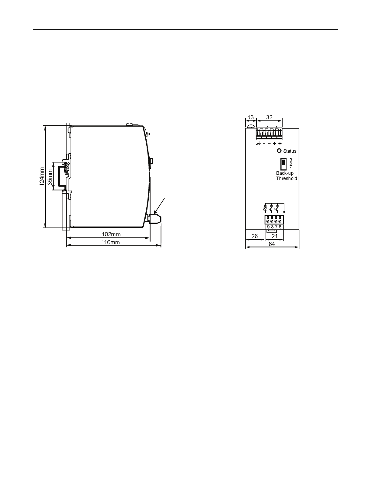
19. Physical Dimensions and Weight
Width 64mm / 2.51’’
Height 124mm / 4.88’’
Depth 102mm / 4.02’’ plus depth of DIN rail and depth of signal connector
Weight 740g / 1.63lb
DIN Rail Use DIN rails according to EN 60715 or EN 50022 with a height of 7.5 or 15mm
Fig. 19-1 Side view Fig. 19-2 Front view
Signal
Connector
All parameters are specified at 24V, 20A, 25°C ambient and after a 5 minutes run-in time, unless noted otherwise.
Rockwell Automation Publication 1606-RM026A-EN-P — April 2014 11
Page 12
Bulletin 1606 Switched Mode Power Supplies
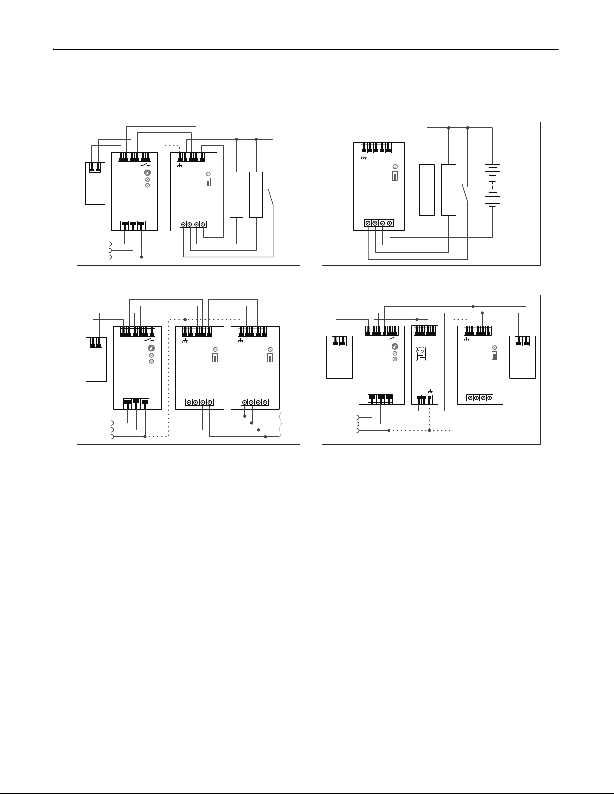
20. Wiring Diagrams
Fig. 20-1 General wiring diagram Fig. 20-2 Signals supplied from an external voltage
L N PE
+ +
- -
Power
Supply
Adj
Overload
DCok
optional
L
N
PE
+ +
- -
XLS
Buffer Unit
Back-up
Threshold
Status
6 +
7 Active
8 Ready
9 Inhibit
Load
+
-
Inhibit
Active
Relay, lamp or signal
Ready
Relay, lamp or signal
+
+ +
- -
XLS
Buffer Unit
Back-up
Threshold
Status
6 +
7 Active
8 Ready
9 Inhibit
Inhibit
Active
Relay, lamp or signal
Ready
Relay, lamp or signal
Fig. 20-3 Paralleling of buer units Fig. 20-4 Decoupling of buered branches
L N PE
+ +
- -
Power
Supply
Adj
Overload
DCok
optional
L
N
PE
+ +
- -
XLS
Buffer Unit
Back-up
Threshold
Status
6 +
7 Active
8 Ready
9 Inhibit
Load
+
-
+ +
- -
XLS
Buffer Unit
Back-up
Threshold
Status
6 +
7 Active
8 Ready
9 Inhibit
L N PE
+ +
- -
Power
Supply
Adj
Overload
DCok
optional
L
N
PE
+ +
- -
XLS
Buffer Unit
Back-up
Threshold
Status
6 +
7 Active
8 Ready
9 Inhibit
Un-
buffered
Load
+
-
XLSRED
Decoupling
Module
+
-
OUT
+
-
IN 1
+
-
IN 2
Buffered
Load
+
-
12 Rockwell Automation Publication 1606-RM026A-EN-P — April 2014
All parameters are specified at 24V, 20A, 25°C ambient and after a 5 minutes run-in time, unless noted otherwise.
Page 13

Page 14

Rockwell Automation Support
Rockwell Automation provides technical information on the Web to assist you in using its products.
At http://www.rockwellautomation.com/support
notes, sample code and links to software service packs, and a MySupport feature that you can customize to
make the best use of these tools. You can also visit our Knowledgebase at http://
www.rockwellautomation.com/knowledgebase for FAQs, technical information, support chat and forums,
software updates, and to sign up for product notification updates.
, you can find technical manuals, technical and application
For an additional level of technical phone support for installation, configuration, and troubleshooting, we offer
Tech Co nn ec t
representative, or visit http://www.rockwellautomation.com/support/
SM
support programs. For more information, contact your local distributor or Rockwell Automation
.
Installation Assistance
If you experience a problem within the first 24 hours of installation, review the information that is contained in
this manual. You can contact Customer Support for initial help in getting your product up and running.
United States or Canada 1.440.646.3434
Outside United States or Canada Use the Wor ldw ide Lo cato r at http://www.rockwellautomation.com/rockwellautomation/support/overview.page, or contact your local
Rockwell Automation representative.
New Product Satisfaction Return
Rockwell Automation tests all of its products to help ensure that they are fully operational when shipped from
the manufacturing facility. However, if your product is not functioning and needs to be returned, follow these
procedures.
United States Contact your distributor. You must provide a Customer Support case number (call the phone number above to obtain o ne) to your
Outside United States Please contact your local Rockwell Automation representative for the return procedure.
distributor to complete the return process.
Documentation Feedback
Your comments will help us serve your documentation needs better. If you have any suggestions on how to
improve this document, complete this form, publication RA-DU002
literature.rockwellautomation.com/idc/groups/literature/documents/du/ra-du002_-en-e.pdf.
Publication 1606-RM026A-EN-P — April 2014
, available at http://
Copyright © 2014 Rockwell Automation, Inc. All rights reserved. Printed in the U.S.A.
 Loading...