

Page 1

IntelliVAC™ Contactor
Control Module
USER MANUAL
(Series C and later)
Bulletin 1503VC
Page 2
Important User Information
IMPORTANT
Read this document and the documents listed in the Additional Resources section about installation, configuration, and
operation of this equipment before you install, configure, operate, or maintain this product. Users are required to
familiarize themselves with installation and wiring instructions in addition to requirements of all applicable codes, laws,
and standards.
Activities including installation, adjustments, putting into service, use, assembly, disassembly, and maintenance are required
to be carried out by suitably trained personnel in accordance with applicable code of practice.
If this equipment is used in a manner not specified by the manufacturer, the protection provided by the equipment may be
impaired.
In no event will Rockwell Automation, Inc. be responsible or liable for indirect or consequential damages resulting from the
use or application of this equipment.
The examples and diagrams in this manual are included solely for illustrative purposes. Because of the many variables and
requirements associated with any particular installation, Rockwell Automation, Inc. cannot assume responsibility or
liability for actual use based on the examples and diagrams.
No patent liability is assumed by Rockwell Automation, Inc. with respect to use of information, circuits, equipment, or
software described in this manual.
Reproduction of the contents of this manual, in whole or in part, without written permission of Rockwell Automation,
Inc., is prohibited.
Throughout this manual, when necessary, we use notes to make you aware of safety considerations.
WARNING: Identifies information about practices or circumstances that can cause an explosion in a hazardous environment,
which may lead to personal injury or death, property damage, or economic loss.
ATTENTION: Identifies information about practices or circumstances that can lead to personal injury or death, property
damage, or economic loss. Attentions help you identify a hazard, avoid a hazard, and recognize the consequence.
Identifies information that is critical for successful application and understanding of the product.
Labels may also be on or inside the equipment to provide specific precautions.
SHOCK HAZARD: Labels may be on or inside the equipment, for example, a drive or motor, to alert people that dangerous
voltage may be present.
BURN HAZARD: Labels may be on or inside the equipment, for example, a drive or motor, to alert people that surfaces may
reach dangerous temperatures.
ARC FLASH HAZARD: Labels may be on or inside the equipment, for example, a motor control center, to alert people to
potential Arc Flash. Arc Flash will cause severe injury or death. Wear proper Personal Protective Equipment (PPE). Follow ALL
Regulatory requirements for safe work practices and for Personal Protective Equipment (PPE).
Allen-Bradley, Rockwell Software, Rockwell Automation, and TechConnect are trademarks of Rockwell Automation, Inc.
Trademarks not belonging to Rockwell Automation are property of their respective companies.
Page 3

Product Description Chapter 1
Table of Contents
Scope ...................................................................................................... 1-1
Description ........................................................................................... 1-1
IntelliVAC Features ..................................................................... 1-2
IntelliVAC Versions .................................................................... 1-3
Specifications ........................................................................................ 1-4
Mount ing a nd Connectio ns ....................................................... 1-4
Configuration ............................................................................... 1-4
Firmware ....................................................................................... 1-4
Electrical Ratings (Table 1.A) ..................................................... 1-5
Mechanical Ratings (Table 1.B) ................................................. 1-6
Altitude Derating (Table 1.C) ................................................... 1-6
Introduction ..........................................................................................1-1
Re ceiving and Stor age Chapter 2
Receiving .............................................................................................. 2-1
Storage ................................................................................................... 2-1
Installation and Wiring Chapter 3
General Precautions ............................................................................. 3-1
Safety and Codes .................................................................................. 3-1
Arrangements ....................................................................................... 3-2
Integral to an Allen-Bradley MV Controller ............................ 3-2
OEM .............................................................................................. 3-3
Fuse Protection .................................................................................... 3-5
Gr ou ndi ng ............................................................................................ 3-5
Connections ......................................................................................... 3-6
Control Power .............................................................................. 3-6
Status R elays ................................................................................. 3-6
Interface Connections ................................................................. 3-7
Wiring Guidelines Electrically Held Contactors ............................. 3-8
Control with Solid-Stat e Devices ............................................... 3-9
Two-Wire Control ................................................................... 3-10
Three-Wire Control ................................................................. 3-11
Wiring Guidelines Mechanical Latch Contactors ........................ 3-13
Mechanical Latch Contactors ......................................................... 3-14
Capacitor Trip ........................................................................... 3-14
Motor Jogging Control .................................................................... 3-16
Undervoltage Protection ................................................................. 3-17
Time Delay Undervoltage ................................................................ 3-17
1503-U M052D-EN-P – Jun e 2013
Page 4

ii Table of Conte nts
Setup and Commissioning Chapter 4
IntelliVAC Configuration .................................................................. 4-1
DIP Factory Default Settings (Table 4.A) ........................................ 4-2
IntelliVAC DIP Switch Explanation (Table 4.B) ............................ 4-2
Moni tori ng and Troubleshooting Chapter 5
Introduction ......................................................................................... 5-1
Module Status ...................................................................................... 5-1
Contactor Status .................................................................................. 5-2
IntelliVAC Status Indication, S eri es C (Table 5.A) ................ 5-3
IntelliVAC Status Indicati on, Seri es D (Ta ble 5.B) ................ 5-4
Module Troubleshooting (Table 5.C) ....................................... 5-5
Min. IntelliVAC Operatio nal Supp ly Vo lta ges ( Tab le 5.D )........ 5-6
Spare Parts Chapter 6
Spare Parts List ..................................................................................... 6-1
Optional Equipment ................................................................... 6-1
Appendix A Typical Contactor Drop-out Time Settings
Typical Contactor Drop-out Tim e Settings (Table A.1) .............. A-1
1503-UM 052D- EN-P – Jun e 2013
Page 5
Chapter 1
Product Description
Introduction Thi s docu ment cont ains i nfor mat ion fo r the Allen-Bradley Bulletin
15 03VC I ntelli VAC™ co ntrol module. The Bullet in 1503 VC is used to
control t he Allen-Br adley Bullet in 15 02 va cuum cont actors t hat a re a
signifi cant component of the Bulletin 1500/1900 CE NTER LINE
Medium Voltage Motor Controllers offered by Rockwell Automation.
An IntelliVAC control modu le may a lso b e pr ovided as a loose
component, for application with a Bulletin 1502 contactor by a third
party (OEM).
Scope Thi s docu ment app lies t o Seri es C (or la ter ) ver sion o f Int elliVAC.
Refer to publication 1503-UM051_-EN-P for information related to
the Series A and B designs.
Description
Intelli VAC is an effici ent a nd flexible solut io n for cont rolli ng m edium
vo lta ge va cuum cont actors used in m otor sta rter and feeder
applications. IntelliVAC may be used to control both 400 and 800
Amp co nta ctors. E lectrica lly held and mecha nica lly la tched cont act or
types can be controlled with IntelliVAC.
1503-U M052D-EN- P – Ju ne 2013
Page 6
1-2 Product Description
Micro Controller
Contactor Coil(s) Interface
Configuration
Inputs
(DIP
switches)
Command
Inputs
Current
Regulator
IGBT Coil
Switching
CC
Input
Power
Conditioning
Coil Current Transducer
Vacuum Contactor
Close Coil
Vacuum Contactor
Trip Coil
Supply
Voltage
110-240
VAC
or
110-250
VDC
Close
Signal
Open
Signal
Vacuum Contactor
Auxiliary
C
C
External
Capacitor
(Optional)
Module
Status
Contactor
Status
Aux.
Feedback
Status
Outputs
c
Altitude
Select
Drop-Out
Select
TDUV
Time
Select
Contactor
Select
c
c
c
c
cc
c
c
c
c
c
Flash EEPROM
Interface
Coil
Power
Supply
Control
Power
Supply
Power Up
Safety
c
c
c
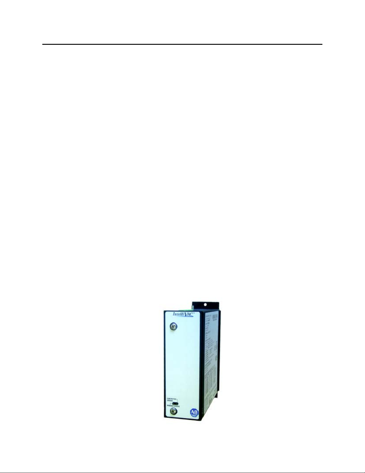
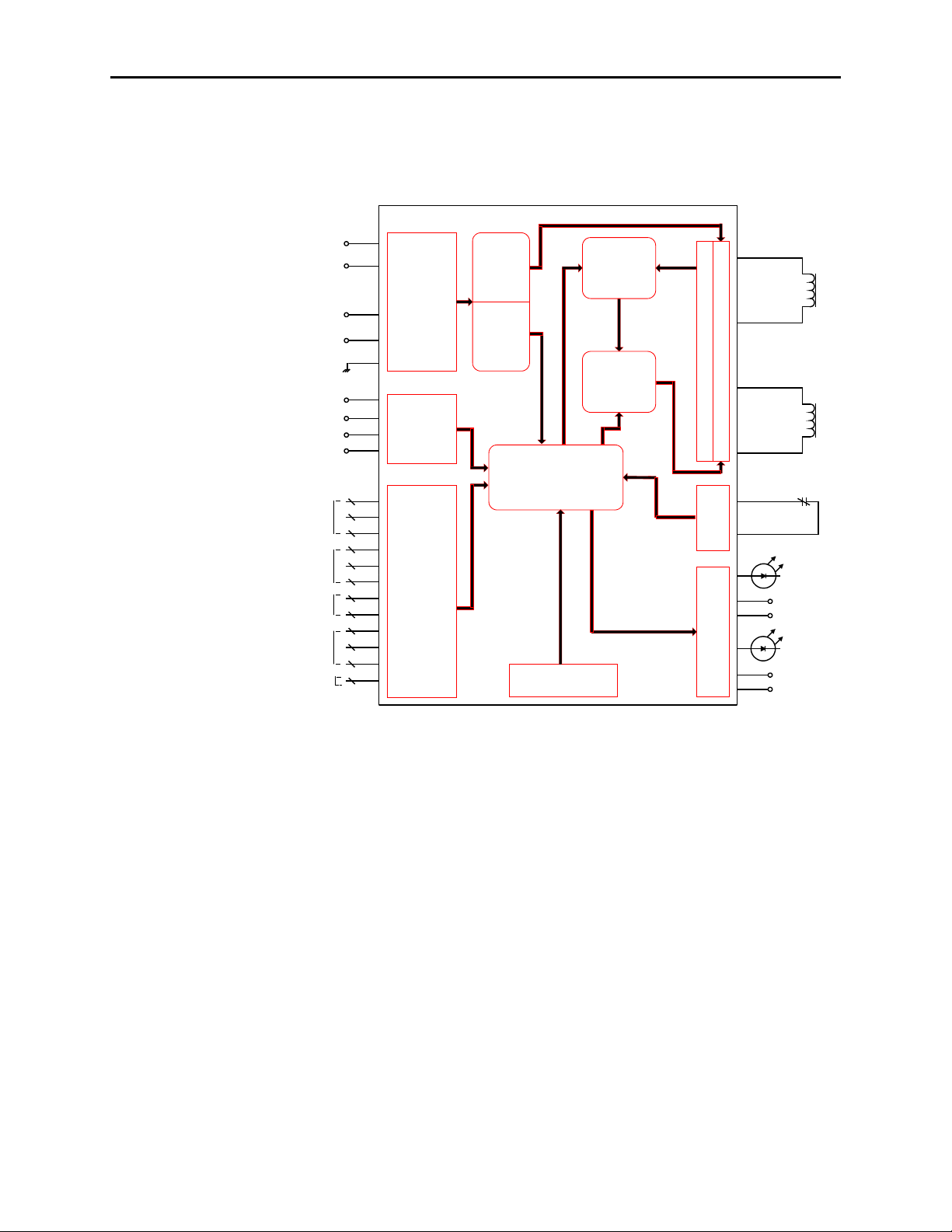
Description (cont.)
Figure 1.1 – IntelliVAC Contactor Control Module
Figure 1.2 – IntelliVAC Block Diagram
IntelliVAC Features
A wi de ra nge of supp ly vo lta ge (11 0 – 240 V AC 50/60 Hz, 110 -
250 V DC) a llows i mplementation i n multiple ap plications
Co nsist ent vacuu m conta ctor p ick-up t ime (a t a g iven sup ply
voltage) ensures repea ta ble per for mance
Selectable va cuum cont act or dr op-out time improves coordination
with upst rea m po wer fu ses
1503-U M052D- EN-P – Jun e 2013
Elect roni c alt it ude compensation (40 0 A only) eli mi nat es
mechanical compensat ion r equi red for alt it udes a bov e 1,0 00
met ers (800 A contactors include a user -fri endly a lti tu de
adjustment)
Page 7

Product D escri ption 1-3
Power loss ri de-throug h (TD UV) a llows t he va cuum cont actor to
rem ai n closed du ring short po wer lo ss (may r equi re a n opt io nal
ext erna l capacitor, dependa nt on ride-thr ough time)
1503-U M052D-EN-P – Jun e 2013
Page 8

1-4 Product Description
IntelliVAC Features (cont.)
Anti-kiss and ant i-pu mpi ng pro tecti on ensure tha t t he vacuu m
contactor close – open sequence occurs as expected, avoiding rapid
re-closur e due t o fault y contro l devi ces
Delayed r estart pr ot ects the va cuum cont actor b y ensuri ng t hat the
rated dut y cycle is not exceeded
Tempo rary jog funct io n (electrically held conta ctors o nly) a llows
the motor to be po sit ioned f or p rocess set -up
IntelliVAC Versions
Series A
Series B
Series C
Up dat ed versi on o f the Seri es B module.
Ther e are t wo ver sio ns of Int elliVAC control. The
fi rst type i s used to cont ro l vacu um co nta cto rs that are
electrically held, with a single electrical coil t hat is
economized electronically. The second is used to
control m echanica lly latched vacu um contact ors.
There is a single version of IntelliVAC, to control
bo th elect ri cally held and mechanically lat ched
va cuum cont act ors.
Series D Minor funct ionali ty (f irmware) enha ncement s
(primarily related to definition and handling of Faults
and Wa rnings).
Refer to Cha pt er 6, for ca talog num bers fo r each ver sio n of Int elliVAC.
Note: A Series C or Series D IntelliVAC module can be used to
rep lace a Seri es A or Series B module. When rep laci ng an
old er series of Int elliVAC wit h a newer one, note that the
Mod ule and C ontact or S ta tus ou tpu ts may funct ion
di fferent ly. Refer t o publicat ion 150 3-UM051_-EN-P
and/ or Chapt er 5 of t his docum ent, and make a ny necessa ry
cha nges t o the cont rol ci rcuit.
1503-U M052D- EN-P – Jun e 2013
Page 9

Product D escri ption 1-5
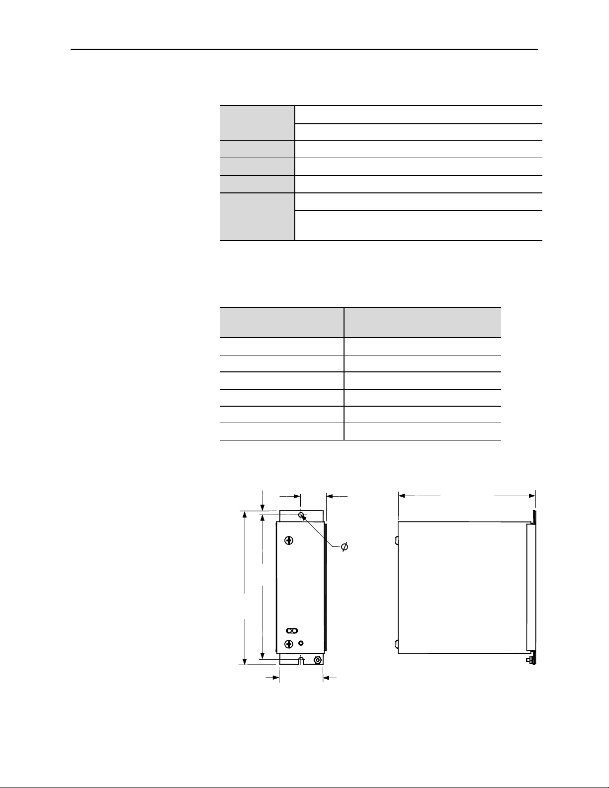
Specifications Mounting and Connections
The IntelliVAC control m odules ar e mou nted usi ng t wo ( 2) scr ews ( see
Figur e 1.3 ). They ar e typi cally lo cat ed in the lo w v oltage control p anel
of t he m ediu m vo lta ge controller (Bullet in 1 500/ 1900 cont rollers, in
the case of Rockwell Automation).
IntelliVAC is int erfa ced t o the Bullet in 150 2 va cuum cont act ors u sing
a “qui ck” co nnecto r, located a t t he mo dule, a wir e ha rness and “qui ck”
connect or at the contact or. Co ntr ol po wer a nd other cont rol circu it
connect ions are similarly achi eved wi th “qui ck” co nnecto rs.
Configuration
IntelliVAC is easily confi gur ed for a wi de va riet y of medi um vo lta ge
mo to r and feeder cont rol app licat ions. It is confi gur ed usi ng D IP
swi tches, located wi thi n the enclosur e (fr ont si de). Plea se refer to
Chapter 4 for information.
Bulletin 1500/1900 controllers are shipped with IntelliVAC preconfi gur ed for t he requ ired a ppli cat ion. Please refer to the docu ment s
pr ovi ded with t he or der.
Firmware
IntelliVAC ha s fir mwa re stored in flash EEP ROM; t herefore, thi s ma y
be upd ated i n the fi eld (if necessary). The IntelliVAC
is up dat ed usi ng t he mi ni-DIN connect or, which i s accessible i nside the
enclosure.
The firmware ver sion sup plied wi th the modu le is disp layed o n to p of
the DIP swi tches ( see Fig ure 4.1) .
Series C modules use only version 2. 003 appli cat io n fir mware. Thi s
fi rmwa re is also com pat ible wi th t he Ser ies A and B modules. Series D
mo dules use only versi on 3.0 01 or 3.0 02 a pplication fi rmwa re. Thi s
fi rmwa re is not compa ti ble wi th any other Series Let ter modules.
Refer t o Cha pt er 6 for p art numb ers of t he va riou s series of m odules.
The Series Letter of the mo dule i s pr int ed on t he lab el on t he cover of
the module, besi de t he part num ber.
board firmware
1503-U M052D-EN-P – Jun e 2013
Page 10

1-6 Product Description
Table 1 .A – Electri cal Ratin gs
Main Inpu t Vo ltage
(L1 to L2/N)
AC – 110 to 240 V rms, +10/-15% , 47 to 6 3 Hz
DC – 1 10 to 250 V, +10/-15%
Main Input Current
(L1 to L2/N )
Command Inputs
⊇ ⊂
Desc ription
Con tac tor Ratin gs
(A mps)
Control Voltage
(AC o r DC)
Inr ush Current 400/800 120/240
Idle Curre nt
(Maximum without contactor coil
400/800 120/240 125 mA 35 mA
energized)
Hold Current ⊄ (maximum)
400/800 120/240 300 mA 100 mA
120 4.6 A 3.6 A
400
Close Current ⊄
(0.2 sec)
240 3.4 A 3.3 A
120 11.3 A 4.8 A
800
240 8.9 A 4.5 A
120 7.0 A 3.7 A
400
Trip Curr ent ( latch) ⊄
(0.2 sec)
240 3.6 A 2.0 A
120 7.0 A 3.3 A
800
240 4.3 A 1.9 A
AC – 100 to 240 V r ms
DC – 50 to 250 V
Max imum on state current f or open or close command:
@ 250 V A C, 60Hz, TA = 60°C
9mA
AC
9mA
@ 250 V DC, TA = 60°C
DC
Minimum on state curr ent f or open or close command:
@ 100 V A C, 60Hz, TA = 60°C
2mA
1.2 m A @ 50 V DC, T
AC
= 60°C
A
Max imum off state current for open or close command:
= 60°C
A
= 60°C
A
700 µA @ 20 V AC, 60 Hz, T
900 µA @ 30 V DC, T
AC Rating DC Rating
25 A peak (1/2
cycle )
25 A peak
1503-U M052D- EN-P – Jun e 2013
Status Output Contacts
Standards and Approvals
⊇ T
Ambient Temperature
A =
⊄ Includes idle current.
⊂ Ensure compatibility of IntelliVAC input ratings with those of circuit components activating these inputs.
Consider means of isolating/loading these signals, as required (using interposing relays or load resistors.)
Consult factory for assistance, if needed. The Series C and D IntelliVACs a re compatible with most PLC outputs,
and have been verified with Rockwell Automation OA type 120V triac outputs. See Chapter 3, Wiring Guidelines.
AC – 250 V rms, 5 A, R load; 2 A (reactive), PF = 0. 4
DC – 30 V, 5 A, R load; 2 A (reactive), L/R = 7 ms
CE, cULus, CSA, IE C pending
Page 11
Product D escri ption 1-7
5.1 (0.20)
Dimensions in mm (inches)
29.7
(1.17)
174.8
(6.88)
185.3
(7.29)
59.4
(2.34)
165.9 (6.53)
5.8 (0.228)
2 places
5.1 (0.20)
Dimensions in mm (inches)
29.7
(1.17)
174.8
(6.88)
185.3
(7.29)
59.4
(2.34)
165.9 (6.53)
5.8 (0.228)
2 places
Specifications (cont.)
Table 1 .B – Mechanical Ratin gs
Ope rat ing: 0° to 60°C ambient at the control module
Tempe rature
Non-Opera ting: -40° to 85°C
Altitud e
Po llution
Hu midity
Shock and Vibration
(Operational)
Ambient temperature is derated at altitudes above 1,000 meters (3,300 feet).
Please refer to Table 1.C.
-1000 to 5000 meters
Pollution lev el II (as def ined by UL 840 and IEC 60664-1)
95% non-condensi ng
Shock – 15 g peak, 11 milliseconds
Vibration – 10 to 57 Hz, 0.015 inch displacement peak to peak
– 57 to 150 Hz, 2.5 g acceleration
Table 1 .C – Altitude Derating
Altitude
-1000 to 0 60
1 to 1000 60
1001 to 2000 58
2001 to 3000 56
3001 to 4000 54
4001 to 5000 52
Maximum Operating Ambient
at the control module (°C)
Derate by 2°C / 1000 m for high altitude operation
Figure 1.3 – Mechanical Dimensions
1503-U M052D-EN-P – Jun e 2013
Page 12

Chapter 2
Receiving and Storage
Receiving Up on receivi ng t he controller, remov e the packing and check for da ma ge
tha t ma y have o ccurr ed during shi ppi ng. Rep ort any d amage i mmedi ately
to the cla ims offi ce of the carrier.
NOTE: If t he Int elliVAC m odu le i s an i nteg ral compo nent o f a
com plete MV co ntr oller (Bullet in 15 00/ 1900), speci al r eceiving and
ha ndling inst ruct io ns will apply. For deta ils, refer to the ser vice ma nua l
pr ovi ded with t he equipm ent.
Storage It is important to consider the following storage requi rement s if y ou a re
not inst alli ng your controller i mm ediately aft er receivi ng i t.
• St ore t he controller i n a clean, dr y, d ust-free environment.
• St ora ge t emper at ure sho uld b e maint ai ned bet ween -40°C and 85°C (40°F and 185°F).
• Relati ve hum idity mu st no t exceed 95%, non-condensing.
1503-UM052D -EN-P – Jun e 2013
Page 13

2-2 Receiving and Storage
(This page is intentionally left blank)
1503-U M052D- EN-P – Jun e 2013
Page 14
Chapter 3
A T T E N T I O N
A T T E N T I O N
A T T E N T I O NA T T E N T I O N
A T T E N T I O NA T T E N T I O N
Safety and Codes
Installation and Wiring
General Precautions In add iti on to the precaut ions li sted thr ougho ut this manual, t he
followi ng st at ement s, whi ch ar e gener al to the syst em, m ust be rea d and
understood.
The cont roller cont ai ns ES D (electrost at ic
discharg e) sensi ti ve p arts and assemblies. St at ic
control p recaut io ns ar e required when
inst alli ng test ing, ser vicing, o r repa ir ing t he
assembly . Co mpo nent da mage may r esult if
ES D cont rol pr ocedures are not fo llowed. I f
you are not familiar with static control
pr ocedures, refer t o app lica ble ES D pro tect io n
handbooks.
An incorrect ly a ppli ed or i nsta lled cont roller
can dam age compo nents o r reduce pr odu ct li fe.
Wi ri ng or a pplication erro rs, such a s incor rect
or ina dequ ate AC su pply, o r excessi ve ambi ent
temper at ures, may resu lt i n ma lfunct ion of t he
system.
Only personnel fam ili ar wi th t he controller a nd
associ at ed machi nery sho uld plan or i mplement
the installation, start-up, and su bsequ ent
ma intena nce of t he syst em. Fai lure t o do thi s
ma y r esult i n persona l injury and/or equipment
damage.
1503-U M052D-EN- P – Ju ne 2013
Page 15
3-2 Installation and Wir ing
A T T E N T I O N
A T T E N T I O N
The Canadi an E lectri cal Co de (CEC ),
Na ti ona l Electrical Co de (N EC), or ot her local
cod es out line p rov isi ons fo r safely i nsta lling
electrical equi pment. Inst alla ti on MU ST
com ply wi th speci fica ti ons rega rding wi re type,
conduct or si zes, bra nch circui t prot ecti on,
int erlock ing and di sconnect devi ces. Fa ilure t o
do so may r esult in perso nal i njur y and/ or
equi pment da mage.
Arrangements
Integral to an Allen-Bradley M V Controller
The Int elliVAC i s ava ila ble a s a pri ma ry co mponent of a n Allen-Bradley
The Int elliVAC i s offer ed in two arrangements, Integr al ( par t of a
Bulletin 1500 /190 0 MV co ntr oller) or as an OEM co mponent .
Bulletin 1500/1900 MV controller as shown in Figure 3.1.
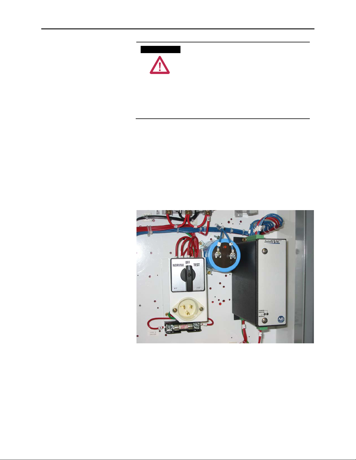
Figure 3.1 – Typical IntelliVAC Install atio n within a Bulletin 15 00/19 00 MV Con troller (Shown
with optional extern al capacit or)
1503-U M052D- EN-P – Jun e 2013
Page 16

Installati on a nd Wiri ng 3-3
OEM
The Int elliVAC may be o rder ed as an OEM com ponent. Thi s allows the
OEM t o mou nt t he com ponents in a confi gura ti on m ost sui tab le to t he
mo to r controller eq uipm ent la yout . Ca re must be exerci sed to ensur e t he
Intelli VAC ha s adeq uate ventila tion pro vided arou nd it. R efer t o Fi gur e
3.2 fo r mount ing t he Int elliVAC. It is recom mended that a mini mum o f
1. 5 inches ( 38. 1mm ) of free a ir space be p rov ided between the
Intelli VAC and any solid b arri er a bov e or belo w.
The OEM i s responsible for controller fusi ng, motor overload protection,
control d evices (eg . Start/Stop push buttons), and wiring between the
Intelli VAC and 1 502 v acuu m cont actor (using o ptional wi re ha rness).
Wi ri ng and mou nti ng fo r op tional i tems, su ch as TD UV C apa cit or, are
also the OEM’ s respo nsib ili ty. R efer t o Fi gure 3.3 for basi c connect ions.
1503-U M052D-EN-P – Jun e 2013
Page 17

3-4 Installation and Wir ing
38.1
(1.50)
38.1
(1.50)
6.4 (0.25)
Additional Modules
(as required)
Minimum bottom clearance
Minimum top clearance
Dimensions in mm (inches)
38.1
(1.50)
38.1
(1.50)
6.4 (0.25)
Additional Modules
(as required)
Minimum bottom clearance
Minimum top clearance
Dimensions in mm (inches)
Arrangements (cont.)
Figure 3.2 – Typical Mounting Configurations
Note: Adja cent Int elliVAC modules ma y be mounted wit h a
minimum separation of 6.4 mm (0.25 i nches).
1503-U M052D- EN-P – Jun e 2013
Page 18
Installati on a nd Wiri ng 3-5
*
Refer to Table 3.A for recommended fuse sizing.
MOV
32
1
EC
-
+
4
TCO
12
11
AUX CCO
5
6
L1 L2/NG
+ -
STOP
START
OVERLOAD
CONTROL
POWER
FUSE
*
7 8
OPEN
16
15
CONTACTOR
STATUS
M
M-INTELLIVAC
M
CAPACITOR
(OPTIONAL)
+ -
9 10
CLOSE
14
13
MODULE
STATUS
INPUT POWER
CONFIGURATION
DIP SWITCHES
*
-
+
+ -
*
7 8
+ -
CONTROL POWER
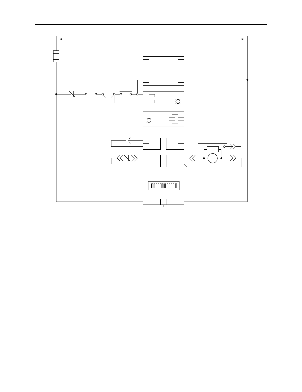
Figu re 3.3 – IntelliVAC Typical Schematic (Electrically Held Vacuum Co ntactor)
1503-U M052D-EN-P – Jun e 2013
Page 19

3-6 Installation and Wir ing
A T T E N T I O N
A T T E N T I O N
Fuse Protection The IntelliVAC module requires external fuse protection to coordinate
wi th t he power supply and co nta cto r. The fuse ratings sho wn in Table
3.A allow the passage of inrush currents expected when the contactor is
closed , or fro m reco mm ended external ca paci to rs fo r the TD UV o pti on.
They will also protect the cont act or coils in t he ev ent o f a modu le
malfunction.
The recommended fuses have been tested to ensure reliable protection of
the module. If t he supp ly vo lta ge is DC, the m odule m ust b e used wit h an
ext erna l fuse t hat is a ppr oved fo r and r at ed to interrupt the D C vo ltage
supply . The t ypes listed a re Ferraz-Sha wmut Mid get Fuses ( 1-1/2" X
13/32"). The TRM is a time-dela y t ype, rated 2 50 VAC. The ATM is a
fast-a cti ng type, rated 5 00 VDC.
Table 3 .A – IntelliVA C Fuse Protection
Rated Supply Voltage Contactor Type
400A EH TRM 2 T RM 3.2
110/120 VAC
220/240 VAC
125 VDC
250 VDC
EH = Electrically Held vacuum contactor
ML = Mechanical Latch vacuum contactor
800A EH
400/800A ML
400A EH TRM 2 TRM 6.25
800A EH
400/800A ML
400A EH/ML
800A EH/ML ATM 5 ATM 6
400A EH/ML
800A EH/ML
Recommended Fuse
(min imum) (ma ximum)
TRM 2
TRM 2
TRM 2
TRM 2
ATM 3
ATM 3
ATM 5
TRM 6.25
TRM 3.2
TRM 6.25
TRM 6.25
ATM 3
ATM 5
ATM 6
Note: If ext erna l ca pacit ors a re connect ed, o r more t han one
Intelli VAC mod ule is pr otect ed by a common cont rol fuse, the
ma xi mum recomm ended fuse should be used to pr event fu se
op ening due to increa sed i nrush current when control po wer i s
applied.
Grounding The Intelli VAC module must be connect ed to a common ground
term ina l (P E) o n the controller p anel. The ground termina l is locat ed on
the bot to m of m odu le enclosur e (refer to Fi gure 3.4 ).
It is important that IntelliVAC is properly
gr ounded usi ng the gr ound co nnecti on
provided. Fai lure to do so ma y r esult i n da mage
to equi pment or perso nal injury.
1503-U M052D- EN-P – Jun e 2013
Page 20

Installati on a nd Wiri ng 3-7
1503-U M052D-EN-P – Jun e 2013
Page 21

3-8 Installation and Wir ing
L2/NL1
CONTACTOR STATUS OUTPUT (N.O.)
MODULE S TATUS OUTPUT (N.O.)
POWER INPUT
13 14 15 16
Ground Connecti on
Connections There are three green connectors on the IntelliVAC module for
connect ions to the co ntrol circui tr y. Connect or p lugs a re pr ovi ded wit h
the module. If a ddi ti onal plug s are req uir ed, r efer t o Chapt er 6, Spare
parts.
Control Power
Co ntrol po wer i s appli ed to the module wi th a two -pole co nnecto r
The IntelliVAC can accept either AC or DC cont rol power. R efer t o
Table 1.A for accept ab le i nput power and control signal ratings.
located at the bottom rear portion of the module. Refer to Figure 3.4 for
connections. The ‘L1’ connection is int ended t o be the ‘Hot’ o r ‘+ ’ side
of t he co ntrol po wer, and t he ‘L 2/N’ connect ion i s int ended to be the
‘Neutral’, ‘Return’, or ‘-’ si de of the co ntrol po wer.
St atus Relays
Status r elay connect ions a re accessed wi th a four-po le connect or loca ted
at the bottom front portion of the mo dule. Refer to Figur e 3.4 for
connect ions. Ther e a re two stat us rela ys, ea ch wi th o ne nor ma lly-open
contact:
Module Status: Terminals 13 and 14
Contactor Status: Terminals 15 and 16
Refer to Cha pt er 5 Monitoring and Troubleshooting for a descr ipt io n of
op eration fo r the r elays.
Refer to Table 1.A for electr ical ratings of t he sta tu s relays.
Figure 3.4 – Bottom side connections
1503-U M052D- EN-P – Jun e 2013
Page 22

Installati on a nd Wiri ng 3-9
1503-U M052D-EN-P – Jun e 2013
Page 23

3-10 Installation and Wiring
CONTACTOR INTERFACE
11 128 9 105 6 72 3 41
EX. CAP.
Interface Connections
All other cont rol int erfa ce connect ions are made a t a twelve-pole
connect or loca ted on the to p of the module. Refer t o Figu re 3. 5 and
Table 3.B for connect ions ( and Table 1.A for elect ri cal ra tings).
Refer to the Wiring Guidelines secti on i n this cha pter for gui dance in
ma ki ng connect io ns to the co ntrol circui t.
Figu re 3.5 – Top side co nnections
Table 3 .B – Terminal Assignments for IntelliVAC Interface Connections
Terminal No . Te rmina l De s igna tion Desc ription
1 External capacitor (negat ive)
2 External capacitor (positive)
3 Lat ch tr ip coil (com mon)
4 Lat ch tr ip coil
5 Close coil (common)
6 Close coil
7 Open / Jog comm and
8 Open / Jog command (common)
9 Close command
10 Close command (common)
11 Contactor auxiliary contact
12 Cont actor auxiliary contact
Refe r to T able 1.A for ele ctri cal ratings .
No connection required if option is not used.
Ensure compatibilit y of IntelliVAC input ratings with those of circuit components activating these inputs. Consider means of
isolati ng/loading these signals, as required (using interposing relays or load resistors). Consult factory for assistance, if needed. The
Series C and D IntelliVACs are compatib le wi th most P LC outp uts , and ha ve been verified with Rockwell Automation OA type 120V
triac outputs. See Wiring Guidelines.
For electrically held contactor, this command will energize the close coil output (CCO).
For mechanically held contact or, this command will energize the trip coil output (TCO).
Power connection for TDUV or capacitor trip options
only
Out put for mechanical latch contactor trip coil
Output to close coil of electrically held &
mechanical latch contactors
Input to open a mecha nical latch cont actor or j og
an electrically held contactor (mutually exclusive)
Input to initiate the closure of electrically held and
mechanical latch contactors
Input to indicate the state of the contactor
(typically wired to a normally closed auxiliary
contact )
1503-U M052D- EN-P – Jun e 2013
Page 24

Installati on a nd Wiri ng 3-11
A T T E N T I O NA T T E N T I O N
Wiring Guidelines Electrically
The IntelliVAC can be applied with two- or three-wir e cont rol ci rcuits.
Held Contactors
The cont rol syst em utili zed will deter mi ne the co nfigu ration of t he inpu t
wiring. Consider the following input and output for the type of control
used:
• Term i nals 9 and 10 – Close Contactor
• Ter mi na ls 15 and 16 – Contactor Status
In eit her ca se, the CLOSE i nput must recei ve a ma intained vo ltage hi gh
to keep t he cont act or closed .
Note:
1. When used with electrically held contactors, the IntelliVAC allows
close co mm ands ever y six seconds. This is to ensure the rated
contactor duty cycle is not exceeded.
2. If IntelliVAC powers up configured for an electrically held contactor,
and t he va cuum cont act or i s det ected a s bei ng closed, the mod ule will
not respond t o a close com ma nd unt il the va cuum contactor auxiliary
contact inp ut i s in t he corr ect ( closed) st ate a nd mo dule power is
rem oved a nd re-applied. (See Chapt er 5)
3. In general, a Clo se comma nd sho uld o nly be appli ed 4 seconds aft er
energi zing Int elliVAC .
For E mergency S top a pplications requiring
rem oval of power, a cont act should be placed in
the “L1” co ntrol po wer r ung t o t he I ntelli VAC.
If t he TD UV feat ure i s used, the cont act or wi ll
not open unt il t he progr ammed TDUV t ime
has expired.
1503-U M052D-EN-P – Jun e 2013
Page 25

3-12 Installation and Wiring
-+
3
2
12
11
AUX
MOV
M
TCO
5
6
-+1
EC
CCO
4
9 10
M
CLOSE
N
G
OVERLOAD
*
CONTROL
POWER
FUSE
CONTROLPOWER
M
M-IV
M-IV
L
CR
CR
SOLID STATE
OUTPUT
INPUT POWER
*
Refer to Table 3.A for recom m ended f use sizing.
Cont rol with Solid-State Devices
If contro l devi ces tha t em ploy electroni c or su ppressed o utput circui ts a re
used i n t he rung(s) tha t co ntr ol the i nput s to the I ntelli VAC, alt ernate
arr ang ement s may be r equi red. D evices em ployi ng t ra nsist or or triac
ou tpu t ci rcui ts ha ve fi nit e im peda nce and allow a leak age cu rrent t o flow
in t he b locki ng o r off st at e. Some P LC a nd I/O m odu les wit h rela y
ou tpu ts a lso ha ve R-C snub ber cir cuits across the cont acts t o suppr ess
noise generated d uri ng cont act openi ng. The im peda nce of these circui ts
also allows leakage cur rent to flo w when t he cont act s ar e open. The hi gh
impedance i nput cir cuit s of the Int elliVAC ma y be t ri gger ed by thi s
leakage cu rrent or r esidua l t ermina l voltage, causing uni ntended
op eration of t he cont act or, or ma intena nce of t he closed st at e when the
control si gna l is removed .
This situation can be p revent ed by co nsideration of t he cont ro l devi ces
when desi gni ng t he co ntrol system. If PL C or si milar control devi ces are
to be int erfaced t o t he Int elliVAC, consider using relay o utpu ts wi th no
suppr ession devi ces a cross the cont act s (the I ntelli VAC input s ar e a hi gh
impedance, resistive loa d). If t his canno t be do ne, consi der the leak age
cur rent of the d evice to see if it is comp at ible wi th I ntelli VAC i nput s (see
Table 1.A) . If not compa ti ble, co nsid er usi ng a n int erpo sing relay
connect ed as shows in Figur e 3.6 .
1503-U M052D- EN-P – Jun e 2013
Figure 3.6 – Co ntr ol wi th So lid -State Devi ces
Page 26

Installati on a nd Wiri ng 3-13
A T T E N T I O N
A T T E N T I O N
A T T E N T I O NA T T E N T I O N
CONTROL
POWER
FUSE
CAPACITOR
(OPTIONAL)
M-IV
EC
TCO
AUX
CCO
L2/N
L1
G
MOV
M
OVERLOAD
RUN
M-IV
CLOSE
* Refer to Table 3.A for recommended fuse sizing.
EMERGENCY STOP
(when required)
M
1
2
4
3
11
6
12 5
CONTROL POWER
Two-Wire Control
Wiring Guidelines Electrically
Held Contactors (cont.)
Som e two-wire control schemes may be configur ed such tha t a close
If usi ng two-wire control, the C LOS E cont act or i nput is m aint ained hi gh
using a single contact. Mom enta rily openi ng t his i nput wi ll cause t he
Intelli VAC to open t he conta ctor. Ma int aini ng t he cont act will pr ovide a
CLOS E command t o I ntelli VAC (gi ven t hat all p ermi ssiv es are sati sfied).
If a fa ult occur s, in a ddit ion t o cycli ng co ntr ol po wer t o the I ntelliVAC
module, the CLOSE command must be removed for a minimum of 4
seconds, before b eing re-app lied. Refer t o Figu re 3. 7.
command is present when IntelliVAC is energized. In this case, the
Power-Up Safet y fea ture may b e disabled by set ti ng D IP swi tch 1 2
accordingly. Refer to Table 4.B.
Only disable the Power-U p saf ety fea tur e when
abso lutely necessa ry. Doing so ca n crea te
unsa fe oper at ing condi ti ons.
For E mergency S top a pplications requ iring
rem oval of power, a cont act should be placed in
the “L1” co ntrol po wer r ung t o t he I ntelli VAC.
If t he TD UV feat ure i s used, the cont act or wi ll
not open unt il t he progr ammed TDUV t ime
ha s exp ired.
1503-U M052D-EN-P – Jun e 2013
Page 27

3-14 Installation and Wiring
A T T E N T I O N
A T T E N T I O N
* Refer to Table 3.A for recommended fuse sizing.
MOV
32
1
EC
-
+
4
TCO
12
11
AUX CCO
5
6
L1 L2/NG
+ -
STOP
START
OVERLOAD
CONTROL
POWER
FUSE
*
M-IV
9 10
CLOSE
M-IV
15 16
CONTACTOR
STATUS
M
M-IV
M
CAPACITOR
(OPTIONAL)
CONTROL POWER
EMERGENCY STOP
(when required)
Figu re 3.7 – Two-Wi re Contro l
Three-Wire Control
If using three-wi re cont rol, t he CLOS E cont actor i nput i s maint ained
hi gh usi ng t wo co nta cts. Momentarily op ening thi s inp ut wi ll cause t he
Intelli VAC to open t he conta ctor. Moment arily closi ng t he START
contact will prov ide a CLO SE co mma nd to I ntelli VAC ( given t hat all
per missives ar e sat isfi ed).
In thi s confi gura tion, t he STATU S outp ut a cts as a seal-in co nta ct. If a
fa ult occu rs, in a ddition t o cycling control power over t o the IntelliVAC
mo dule, the CLO SE co mmand must be removed for a minimum of 4
seconds b efore being r e-ap plied. Refer to Figur e 3.8 .
For E mergency S top a pplications requ iring
rem oval of power, a cont act should be placed in
the “L1” co ntrol po wer r ung t o t he I ntelli VAC.
If t he TD UV feat ure i s used, the contact or will
not open unt il t he progr ammed TDUV t ime
has expired.
Fig ure 3 .8 – T hree-W ir e Con tro l
1503-U M052D- EN-P – Jun e 2013
Page 28

Installati on a nd Wiri ng 3-15
CLOSE COMMAND
TO MICRO
MICRO OUTPUT
TO CLOSE COIL
CONTACTOR STATUS
RELAY OU T P U T
CONTACTOR
AUXLIARY
INPUT TO MICRO
CLOSE LEVEL OF
CURRENT TO CLOSE
COIL
MODULE STATUS
RELAY OUTPUT
Contact status relay closes on request to close. It will open if the contactor auxiliary contact does not close within 200 milliseconds and
module will fault (opening module status relay).
15mS
200mS
90mS
(@120VAC)
80mS
60mS
5mS
SELECTABLE DROP
OUT TIME
(0 TO 190mS)
CLAMP DELAY
DEBOUNCE
NATURAL
CONTACTOR
DROP OUT
CONTACTOR PICK UP
ACKNOWLEDGE
WINDOW
DEBOUNCE
30mS
For this example, the 130 milli s econd drop-out time has been selected. The base drop-out time is 50 milliseconds. The microcontroll er del ay i s
130-50=80 milliseconds.
15mS
Wiring Guidelines Electrically
Held Contactors (cont.)
Figu re 3.9 – Tim ing Diagr am 400A (Electr ically Held ) Contacto r
for IntelliVAC Control with three-wire Control
1503-U M052D-EN-P – Jun e 2013
Page 29

3-16 Installation and Wiring
MOV
32
1
EC
-
+
4
TCO
12
11
AUX CCO
5
6
L1 L2/NG
+ -
CLOSE
OVERLOAD
CONTROL
POWER
FUSE
*
CONTROL POWER
M-IV
9 10
CLOSE
CC
M-IV
M
MOV
TC
M
+ -
M-IV
7 8
OPEN
OPEN
OVERLOAD
* Refer to Table 3.A for recommended fuse sizing.
IntelliVAC control may be u sed for m echanica l la tch co nta ctors.
Wiring Guidelines Mechanical
Latch Contactors
A mom enta ry control signal is needed to close the co nta ctor, a nd a second
mo ment ar y contro l sig nal i s needed to open t he cont actor. The
mo ment ar y op en/close comma nds m ust b e at least 50 m illi seconds in
duration.
Refer to Figur e 3.10 for a ty pical mecha nica l lat ch cont rol schem e.
Note:
1. A mecha nica l lat ch contactor ma y a lready be closed when power is
appli ed to the I ntelliVAC cont ro l module.
2. I t i s permissible to apply an open command to the IntelliVAC
mo dule a s power is re-applied.
Figu re 3.10 – Mechanical Latch Contactor Control
1503-U M052D- EN-P – Jun e 2013
Page 30
Installati on a nd Wiri ng 3-17
Mechanical Latch Contactors
Capacitor Trip
The Int elliVAC can be confi gured to pr ovi de capa cit or trip functionality
wi th m echanical lat ch cont act ors. A capa citor mu st be connect ed t o the
Intelli VAC (term ina ls #1 a nd #2 ) in ord er to pr ovi de thi s capabi lity . The
capa cit or pr ovi des control po wer fo r t he Int elliVAC a s well as sto red
energy t o trip t he contactor. Maxi mum recom mended ca pacitor size i s
1650 µF for 120V control or 330 µF for 240V control. Use o f lar ger
capa cit ors wi ll requi re a cur rent lim iti ng circui t t o pr event openi ng t he
control fuse on energization.
The Int elliVAC must recei ve an ‘OP EN’ comma nd wi thin a few seconds
of losing AC co ntr ol po wer. This t im e lim it dep ends on voltage and
capa cit or size as sho wn in the t able below. If t he elapsed time exceeds thi s
limit, the cont act or ca nnot be t ri pped by I ntelli VAC. In thi s case, t he
contact or ca n be t ripp ed by pressi ng the r elease but to n on t he door i n
front of the contactor.
A sepa ra te vo ltag e sour ce is needed t o pr ovi de the ‘OP EN’ command. This
may be taken from the external capacit or as shown in Figure 3.11.
Table 3 .C – Mechani cal Latch Contactor – Capacit or Trip Times
Con tac tor
Ra ting
400 Amp
No minal Vo lta ge
(Vac)
120
240
Ac tual
V
(Vac )
input
120
110 2.7
100 1.7
240
200 4.7
Note: Minimum capacitor voltage ratings:
Ext. Capa c itor
(µF)
1650
330
Ma x. time
for trip
(sec)
3.5
7.5
• 120V applications – 200V DC (250V DC preferred)
• 240V applications – 400V DC (450V DC preferred)
1503-U M052D-EN-P – Jun e 2013
Page 31

3-18 Installation and Wiring
MOV
32
1
EC
-
+
4
TCO
12
11
AUX CCO
5
6
L1 L2/NG
+ -
CLOSE
OVERLOAD
CONTROL
POWER
FUSE
*
CONTROL POWER
M-IV
9 10
CLOSE
CC
M-IV
M
MOV
TC
M
+ -
M-IV
7 8
OPEN
OPEN
CAPACITOR
OVERLOAD
*
Refer to Table 3.A for recommended fuse sizing.
Figure 3.11 – Mechan ical Latch Contactor with Capacitor Trip Option
1503-U M052D- EN-P – Jun e 2013
Page 32

Installati on a nd Wiri ng 3-19
A T T E N T I O N
A T T E N T I O N
MOV
32
1
EC
-
+
4
TCO
12
11
AUX CCO
5
6
L1 L2/NG
+ -
STOP
START
OVERLOAD
CONTROL
POWER
FUSE
*
CONTROL POWER
M-IV
9 10
CLOSE
M-IV
15 16
CONTACTOR
STATUS
M
M-IV
M
+ -
JOG
M-IV
7 8
OPEN
* Refer to Table 3.A for recommended fuse sizing.
EMERGENCY STOP
(when required)
Motor Jogging Control Note: Jog functiona lit y can work wi th elect ri cally held cont act or o nly.
When used with electrically held contactors, t he IntelliVAC a llows close
com ma nds ever y six seconds. Thi s i s t o ensur e t he r at ed cont act or du ty
cycle o f 60 0 op erations per hour is not exceed ed.
For motor jogg ing oper at ions, t he second co ntr ol input , or O PEN
com ma nd, will close t he cont act or f or a s long a s the inp ut i s present , a nd
op en t he cont act or when t he inp ut i s rem oved. (Refer to Figure 3.12.)
Thi s m etho d will byp ass the st and ard six second mot or r e-sta rt dela y fo r
jogg ing purpo ses only. Opera ti ons will be li mited t o t wo st art s every
twelve seconds.
If t he TD UV feat ure i s used, the cont act or wi ll
not open unt il t he progr ammed TDUV t ime
ha s exp ired. Ther efor e, ap plications requ iring
an i mmedi at e remov al of power du ring
emer gency stop co nditi ons are not compa ti ble
wit h the TDUV feature.
Figu re 3.12 – Motor Jog ging Con tro l
1503-U M052D-EN-P – Jun e 2013
Page 33

3-20 Installation and Wiring
A T T E N T I O NA T T E N T I O N
Undervoltage Protection The Intelli VAC cont roller prot ects t he contact or from cont rol vo lta ge
di ps and loss of p ower. It pro vides underv olta ge relea se a nd pr event s
attempt s to close t he co nta ctor when ther e is no t suffi cient power
ava ila ble t o gu arant ee reliable closi ng o f the cont act s. The under volt ag e
pr otection wi ll be i nit ia ted und er the fo llowi ng co nditions, reg ardless o f
nominal control voltage:
1. I f the supply vo lta ge dr ops b elow 90 V (AC or DC) during the first
20 0 milliseconds aft er a Clo se co mmand i s recei ved. Thi s a ppli es to
bo th elect ri cally held and m echanica l la tch co nta ctors.
2. If t he supply voltage dr ops b elow 72 V (AC or DC) aft er t he 200
millisecond close sequence (electrically held cont act ors only) .
Time Delay Undervoltage
The Int elliVAC can be confi gur ed to p rovide time dela y under voltag e
(TDUV) pr otect ion. The feat ure i s available to keep elect ri cally held
contact ors clo sed during a vo lta ge di p or b rief power loss. This opt io n
ma y r equi re the a ddi ti on of a capa cit or (see belo w). Refer t o Cha pt er 6
for typi cal ca pacitor si zing. The ca paci tor i s connected t o t ermina ls 1(-)
and 2(+) of the IntelliVAC. (Refer to Fi gure 3.1 3.)
If t he TD UV feat ure i s used, the cont act or wi ll
not open until t he prog rammed TD UV t ime
ha s exp ired. Ther efor e, ap plications requ iring
an i mmedi at e remov al of power du ring
emer gency stop co nditi ons are not compa ti ble
wi th t he TDUV fea ture.
Table 4.B of the “S etup a nd Com mi ssioni ng” cha pt er ha s the dip switch
settings t o pr ovi de TDUV fro m 0.2 to 2 seconds. Int elliVAC can
pr ovi de TDUV prot ecti on witho ut t he use of a n ext ernal capa cit or, as
shown in Table 3.D.
Table 3 .D – Maximum TDUV Time (without Capacitor)
Control Voltage
110/120 V
220/240 V
Max. TDUV Time (secs)
400 A 800 A
0.2
1.0
0.2
1.0
If t he underv oltage condi ti on persi sts b eyond t he set dela y t ime, the
contact or will be o pened a nd an undervoltage fault o r warning condition will
occu r (see Cha pter 5) .
1503-U M052D- EN-P – Jun e 2013
Page 34

Installati on a nd Wiri ng 3-21
1503-U M052D-EN-P – Jun e 2013
Page 35

3-22 Installation and Wiring
*
Refer to Table 3.A for recommended fuse sizing.
MOV
32
1
EC
-
+
4
TCO
12
11
AUX CCO
5
6
L1 L2/NG
+ -
STOP
START
OVERLOAD
CONTROL
POWER
FUSE
*
CONTROL POWER
M-IV
9 10
CLOSE
M-IV
15 16
CONTACTOR
STATUS
M
M-IV
M
CAPACITOR
(cont.)
Time Delay Undervoltage
Figure 3.13 – TDUV Control Circuit
1503-U M052D- EN-P – Jun e 2013
Page 36

Chapter 4
S H O C K H A Z A R DS H O C K H A Z A R D
I M P O R T A N TI M P O R T A N T
Rem ove p ower fr om the module befo re
LEDs
Ground Stud
Supply Power Input
Interfac e C onnections
EEPROM Programming Port
(Mini DIN Connector)
DIP Switches
Status Relay Outputs
Internal Cont rol Fuse
Setup and Commissioning
IntelliVAC Configuration The Int elliVAC module i s confi gur ed for a speci fic app lica ti on by set ti ng
DIP switches. They are accessed by loo sening the two screws on the front
of t he uni t, and r emovi ng t he cov er by slidi ng i t for war d. The swi tches
are found on t he front edg e of the I ntelli VAC cir cuit boa rd (see Fi gur e
4.1) . Ther e are 12 swit ches, with nu mber 1 being at the top next to the
mi ni DIN connect or. ( Refer to Table 4. B).
Hazardo us volt age is pr esent insi de the module
whi ch may ca use per sona l i njury o r dea th.
Rem ove a ll sou rces of po wer fro m t he mo dule
and d ischa rge any connect ed cap acit ors b efor e
rem oving the co ver.
rem oving the co ver a nd before cha ngi ng the
DIP switch set ti ngs. The new DIP switch
settings a re reco gni zed o nly on power-up.
Figure 4.1 – DIP Switch and Connector Locations
1503-U M052D-EN-P – Jun e 2013
Page 37

4-2 Setup and Comm issioning
An Intelli VAC unit shi pped sepa ra tely fr om the fa cto ry wi ll hav e a
default configu ration per Table 4 .A.
1503-UM 052D- EN-P – Jun e 2013
Page 38

Setup and Commissio ning 4-3
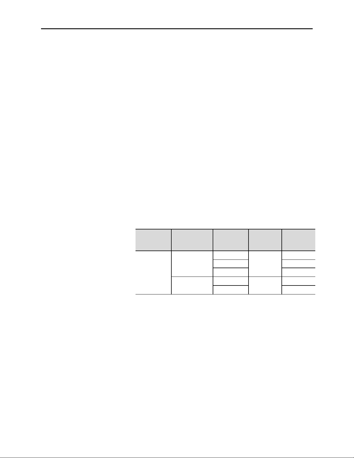
Table 4 .A – DIP Switch Factory Default Settings
1
Table 4 .B – IntelliVAC DIP Switch Explanation
| | |
|
12
0
0 1 1
1 1
0 0
0 1
1 0
1 1
9
0 1
1 0
1 1
DIP switc h
Desc ription 1 2 3 4 5 6 7 8 9 10 11 12
Altitude: 0 – 1000m 0 0 1
Drop-out time: 130 msec 0 1 1
Contactor config.: 400A EH
TDUV config.: No TDUV
Ext. cap TDUV time: 0.2 sec 0 0
Power -Up Safety: Enable 0
0
0
IntelliVAC u nit s shipped in a complet e MV controller (Bullet in
15 00/ 1900 ) wi ll be confi gured to sui t t he installed appli cat ion (i.e.
contact or t ype). The user should veri fy t he settings before energi zing the
equi pment . Table 4.B defines t he sett ing s for each swit ch.
UP = 1
DOWN = 0
1 2 3 4 5 6 7 8 9 10 11 12
Altitud e
-1000 to 0
1 to 1000 0
1001 to 2000
2001 to 3000 0
3001 to 4000
4001 to 5000
Not defined
Not defined
The altitude compensation by DIP switch settings applies to Series E 400 amp vacuum contactors only. All 800 amp contactors are adapted
for altitude by altering the return springs. 800 amp contactors are to be set for 1 to 1000m (001 DIP setting).
1 2 3
0 0 0
0 1 0
1 0 0
1 0 1
1 1 0
1 1 1
Drop out time
50 msec
75 msec 0
100 msec
130 msec
150 msec
175 msec
200 msec 1
240 msec 1
4 5 6
0 0 0
0 1 0 0 0
0 1 1 0 1
1 0 0 1 0
1 0 1 1 1
DIP switch SW1
7 8
Powe r-Up Sa fety
10 11
TDUV c onfig.
0
1
No TDU V
TDUV Enabled
Ena ble
Disable
Ext. cap. TDUV time
0.2 sec
0.5 sec
1.0 sec
2.0 sec
Contactor Config.
400A Mech. Latch
400A Elec. Held
800A Mech. Latch
800A Elec. Held
1503-U M051C-EN-P – Jun e 2005
Page 39

4-4 Setup and Comm issioning
By-pass contactors in MV SMC applications must be set for 50 millisecond drop-ou t time .
Refer to Appendix A for typical drop-out time settings used when power fuses are provided by Rockwell Automation.
1503-UM 052D- EN-P – Jun e 2013
Page 40

Monitoring and Troubleshooting
Introduction
The I ntelli VAC module ha s t wo li ght emi tt ing di odes (L EDs) a nd rela y
ou tpu ts t o indi cat e the stat us of t he conta ctor a nd t he mo dule. The LEDs
are v isi ble on the fro nt o f the mod ule and t he relay outputs are accessed
on the bottom front of the module.
Chapter 5
Figure 5.1 – Int elli VAC L EDs
Note: Thi s u ser manua l cont ai ns information fo r bo th Ser ies C a nd
Seri es D Int elliVAC versions. R efer to the co rrect information
belo w f or t he Intelli VAC seri es in use.
Module Status The Module Sta tus i s ind icat ed with a Green L ED if t he m odule i s
funct ioning pr oper ly a nd has a vali d confi gur at ion. If t he mo dule powers
up with an invalid configur at ion t he LED will be Red (fla shing o nce),
indicating a Fault condition whi ch will no t allow t he cont act or t o clo se. If
the m odule po wers up p rop erly a nd exper iences an undervolt age condit ion
when att empt ing to close the co nta ctor or while t he co nta cto r is closed:
• Series C – the LED will be Red (Fa ult) . If t he cont act or does not
close p rop erly, a Fault is generated, the LED tu rns Red , and inp uts
are i nhi bit ed unti l the m odule power is remov ed and r eapp lied.
• Series D – the LED will be yellow (flashing once). If the
und ervo lta ge condi ti on i s corr ected during the selected TDUV
int erva l (a s set via DIP switch), then no rmal oper at ion resum es.
1503-U M052D-EN-P – Jun e 2013
Page 41

5-2 Monit oring a nd Troubleshoot ing
I M P O R T A N T
I M P O R T A N T
Module Status (cont.) If the pro cessor ha s an int erna l fault , the L ED will be Red, t he out put s
will be cleared, and the processor must be reset (input power must be
cycled). If the reset is successful, the L ED will be Gr een a nd the m odule
wi ll respo nd to t he cont rol input s. The inp ut com ma nd mu st be togg led
before the module wi ll r espond t o a new com mand ( risi ng edg e trigger ed).
For S eri es D, the Mo dule Sta tus L ED i s also used to indicate vari ous
“Warning” co nditions relat ed to the co nta cto r per formance (see Table
5.B).
Mod ule Status o utput relay ha s a normally op en cont act . The co nta ct i s
op en dur ing a Fault condi ti on (LED red) , and closed during a hea lthy
condi tion (LED green). The relay i s o pen for some wa rning condi ti ons,
but closed for less severe issues.
The module stat es ar e summ arized i n Tables 5. A and 5.B.
Contactor Status
Co nta ctor Status o utput relay ha s a normally op en cont act . The co nta ct
The cont act or st at es ar e summ ari zed in Tables 5.A a nd 5.B.
The Contactor Status is indicated with a yellow LED that is off until a
CLOS E command i s recei ved. The yellow L ED will sta y on if t he
contact or clo ses prop erly, until t he cont act or is opened . If the pro cessor
ha s a n int erna l fau lt, the LED will be red.
is open when t he contact or i s open (LE D of f), and closed when t he
contact or has received a close comm and (for 20 0 milli seconds) or if i t i s
closed (LE D on).
The LED s ar e red/ green types with both
sections ON t o pr odu ce yellow. If viewed fr om
a sha rp a ngle, you m ay see only green or r ed.
Please vi ew fr om di rectly in fr ont of t he mo dule
to ensur e a ccura te co lor reco gniti on.
1503-UM 052D- EN-P – Jun e 2013
Page 42

Monitorin g and Troubles hooti ng 5-3
Table 5 .A – IntelliVAC Status Indication (Series C only)
Con dition s
Desc ription
Module Status
LED Color Re lay LED Color Re lay
Norm al Healthy Module and Contactor OPEN Green Closed Off Open
Norm al Healthy Module and Contactor CLOSED Green Closed Yellow Closed
War ning Invalid Com mand Present Yellow Closed Off Open
War ning Mechanical Latch Fail to Trip Yellow Open Yellow Closed
Fa ult Power Up with Contactor CLOSED Red – Flash 2 Open Yellow Closed
Fa ult Contactor Fails to Pick Up Gr een O pen Red – Flash 1 Open
Fa ult Contactor Drop Out During Hold Green Open Red – Flash 2 O pen
Fa ult Long Contactor Drop Out Time Green Open Red – F lash 3 Open
Fa ult Microcontroller Malfunction Red O pen Re d Ope n
Fa ult Power Up with Invalid Dip Switch Configuration
Red – Flash 1 ⊂
Open Off Open
Fa ult Unde rvoltage wit h a CLOSE Comma nd Present Red O pen Of f Ope n
W arning = Recoverable Condit ion – Remove and retry offending signal
Fa ult = No n-recoverable condition – Module power must be removed and re-applied.
Flash 1 = 1 Flash Red LED followed by a pause.
Fl ash 2 = 2 Consecutive Red LED flashes followed by a pause.
Flash 3 = 3 Consecutive Red LED flashes followed by a pause.
Only for Electrically Held Contactor
Invalid Command Types:
1. Close, Jog or Trip commands present during power up sequence.
2. Close or Jog command re-applied to o quickly (be fore contactor o pening sequence is verified).
Allow at least 60 msec, plus drop out delay time, before re-applying thes e signals.
NOTE: Contactor will only respond to a close command re-applications after the re-start delay timer has expired.
3. Close a nd Trip commands present simultaneously (valid with Mechanical Latch contactors only).
U ndervoltage conditions are defined on page 3-17.
Contactor Status
1503-U M052D-EN- P – Ju n e 2013
Page 43

5-4 Monit oring a nd Troubleshoot ing
11
11
12
12
Contactor Status (cont.)
Table 5 .B – IntelliVAC Status Indication (Series D only)
Con dition s
Desc ription
Norm al Healthy Module and Contactor OPEN Green Closed Off Open
Norm al Healthy Module and Contactor CLOSED Green Closed Yellow Closed
War ning Invalid Command Pr esent Yellow Closed Of f Open
War ning Mechanical Latch Fail to Trip Yellow Closed Yellow Closed
Fa ult Power Up with Contactor CLOSED Red – Flash 2 Open Yellow Closed
War ning Contactor Fails to Pick Up Yellow – R1 Closed Off / Yellow O pen/Clos ed
War ning Contactor Drop Out During Hold Yellow – R2 Closed Off / Yellow O pen/Closed
War ning Long Contactor Drop Out Time Yellow – R3 Closed Off / Yellow Open/Cl osed
Fa ult Microcontroller M alfunction Re d O pen Red Open
Fault Power Up with Invalid Dip Switch Configuration
Red – Flash 1 ⊂
War ning Undervoltage with a CL OSE Command Present Yellow – F lashi ng Open/Closed Off / Yellow Open/Close d
W arnings will be cleared when a change of input state occurs, and the condition has been resolved.
Faults require control power to be removed until the unit resets
Flash 1 = 1 Flash Red LED followed by a pause
Flash 2 = 2 Consecutive Red LED flashes followed by a pause
Ye llow – R1 = Yellow with 1 Red flash followed by a pause
Yellow – R2 = Yellow with 2 consecutive Red flashes followed by a pause
Ye llow – R3 = Yellow with 3 consecutive Red flashes followed by a pause
Invalid Command Types:
1. Close, Jog or Trip commands present during power up sequence
2. Close or Jog command re-applied too quickly (be fore contactor o pening sequence is verified).
Allow at least 60 msec, plus drop out delay time, before re-applying thes e signals.
NOTE: Contactor will only respond to a close command re-applications after the re-start delay timer has expired.
3. Close a nd Trip commands present simultaneously (valid with Mechanical Latch contactors only).
Open during undervoltage, Closed if voltage restored
W ill reflect actual status of the contactor
Only for Electrically Held Contactor
Undervoltage conditions are defined on page 3-17.
Module Status Contac to r Status
LED Color
Re lay
LED Color
Open Off Open
Re lay
1503-UM 052D- EN-P – Jun e 2013
Page 44

Monitorin g and Troubles hooti ng 5-5
Module status LED ‘Green’ and Contactor Status LED
Table 5 .C – Module Troubleshooting
Problem or Trip Indicated Indication of the following conditions Possible Solutions
Contactor does not energize • Motor Protection activated
• Both Status LEDs ‘Off’
• Module Stat us LED ‘Red’ upon power up
• Module Status ‘Red Flash 1’ upon power up • Improper set ting of dip switches. Check settings and
• Loose connection in control circuit. • Verify contactor auxiliary set up. Reference Publication
Contactor closes momentarily and will not
reclose.
Contactor fails to close.
• Module status LED ‘Red’ (Series C) and Contactor
Status LED ‘Off’
or
• Module status LED ‘Yellow – Flashing’ and Contactor
Status LED ‘Off’ (Series D)
•
‘Red Flash 1’ (Series C)
or
• Module status LED ‘Yellow-R1’ (Series D) and
Contactor Status LED ‘Off’
• Both status LEDs ‘Of f’ • Check internal control fuse. Verif y IntelliVAC oper ation
• Investigate and reset
• Check Control Power
• Loose connections in control circuit
• V erify Int elliV AC power input plug is in place and
properly seated
• Verify internal control fuse has not opened (Refer to
Figure 4.1 for locat ion)
• IntelliV AC faulted. Cycle control power to reset.
Replace IntelliVAC if unsuccessful.
cycle control power.
1502-UM052_ -EN-P (400A) or 1502-UM051_ -EN-P
(800A ) – Auxiliary Contact Set-up Procedure.
• Verify circuit continuity (is contactor plug connected
proper ly?)
• Under volta ge fault (no TDUV), contr ol volta ge dipped
below trip point. Verify voltage levels ar e 110 to 240
VAC, 110 to 250VDC
• Coil damaged or connections ar e loose. Repair and
cycle control power (Series C).
• Auxiliary Contact Assembly improperly adjusted.
Reference Publication 1502-UM052_ -EN-P (400A) or
1502-UM051_ -EN-P (800A) – Auxiliary Contact Set-up
Procedure. Cycle control power to reset (Series C).
• A rmature Plate obstructed from closing to coil face.
Verify no foreign material behind the armature plate.
Cycle contr ol power to reset.
in test mode bef ore a pplying Medium Voltage. (Refer to
Fig. 4.1 for location.)
Refer t o Table 5. A (Series C) or Table 5. B ( Series D) for definition of Module
LE D sta tes.
1503-U M052D-EN- P – Ju n e 2013
Page 45

5-6 Monit oring a nd Troubleshoot ing
Module Status LED ‘Green’ and Contactor Status LED
R2’ and Contactor Status
Module Status LED ‘Yellow’ and Contactor Status LED
Table 5 .D – Minimum IntelliVAC Operational Supply Voltages
Contactor Status (cont.)
Table 5 .C – Module Troubleshooting (cont.)
Problem or Trip Indicated Indication of the following conditions Possible Solutions
Contactor opens during operation
Contactor does not open (mechanical latch) •
• Motor Protection activated
• Stop command initiated
• M odule Status LED ‘Red’ (Series C)
or ‘Yellow – Flashing’ (Seri es D)
•
‘Red Flash 2’ (Series C)
or
• Module Status LED ‘Yellow –
LED ‘Off’
• Both status LEDs ‘Of f’
‘Yellow’
• Investigate and reset.
• Verify circuit
• Under voltage f ault (no T DUV) , control volt age dipped
below trip point. Verify voltage levels ar e 110 to 240
VAC, 110 to 250 VDC.
• With external capacitor and TDUV feature activated,
undervoltage condition for longer than progr ammed
TDUV time. Undervoltage fault activated.
• Contactor Status feedback between Terminals 11 and
12 on the IntelliVAC has closed. The IntelliVAC will deenergize the coil, t hinking the contactor has opened
for other reasons.
• Check control voltage and inter nal control fuse. ( Refer
to Figure 4.1 for location.)
• T rip me chanism is dam aged. Inspect and replace if
needed.
• Check f or loose connecti ons i n the cont rol circuit .
Cont actor does not open
(electrically held)
• Series C – Module Status LED ‘Green’ and Contactor
Status ‘Red Flash 3’
• Series D – Module Status LED ‘Yellow – R3’ and
Contactor Status LED ‘Yellow’
• Contact or welded or mechanisms binding. Inspect and
repair if needed.
Refer t o Table 5.A (Seri es C) or Tab le 5.B (Seri es D) for definition of Module
LE D sta tes.
Voltage Level
Pick -Up 400/800 95
Drop-O ut 400/800 75
Tr ip (M echanical Latch)
Contactor Rating
(A mps)
400 70
800 80
Minimum Voltage
(VAC, 47 to 63 Hz)
1503-UM 052D- EN-P – Jun e 2013
Page 46

Chapter 6
Spare Parts
Spare Parts List IntelliVAC (elect rically held) Series A 1503VC-BMC1
Intelli VAC (mechani cal la tch) Series A 1503VC-BMC2
IntelliVAC (electrically held and
mecha nica l lat ch) S eries B 1503VC-BMC3
IntelliVAC (electrically held and
mechanical la tch) Seri es C and D
Internal Fuse: 6.3 A, 250 V (Littlefuse 21506.3) 80174-902-14-R
Multi-pole connect ors:
2 pole (m odu le power) 80174-014-01-R
4 p ole (status outputs) 80174-014-03-R
12 pole (co il and I/O co nnecti ons) 80174-014-11-R
1503VC-BMC4
Optional Equipment
TDUV Capacitor
For 110/120V AC control (1650 µF) 80158-779-51-R
For 220/240V AC control (330 µF) 80158-779-52-R
The Series Letter i s print ed on t he lar ge label on the right-hand s ide of th e enclos ure,
Includes mounting bracket and terminal guards
besi de th e part number.
1503-U M052D-EN- P – Ju ne 2013
Page 47

6-2 Spar e Parts
(This page is intentionally left blank)
1503-U M052D- EN-P – Jun e 2013
Page 48

Appendix A
Table A .1 – Typi cal Contactor Dr op-Out Time Settings
4R 6R 9R
18R
19R
2 x 24R ⊇ 100
2 x 32R
⊇
240 *
2 x 38R
⊇
2 x 48X
⊇
⊇
Typical Contactor Drop-out Time Settings
The cont act or d rop -out time settings shown i n the fo llowi ng t able are
typical minimum v alues u sed when the po wer fuses a re pr ovi ded a s part of
a com plet e MV cont roller from Ro ckwell Aut oma ti on. The
recommenda tions a re ba sed on Ferraz-Shawm ut p ower fuses. Ot her fuse
types may req uire a lter nat e dro p-out ti me sett ing s.
The Int elliVAC module D IP swi tches are set up t o pr ovi de the m ini mum
drop-out ti mes shown (refer t o Cha pt er 4) .
Fus e Ra ting Contactor Drop-out Time Setting ( mse c)
Vo ltag e De sign ation 400A 800A
2R
3R
50
12R
< 5000
⊇ Fus e not suitable for use with contactor.
24R
32R
38R ⊇
48X
57X ⊇ 200
2 x 57X
100
240
⊇
⊇
⊇
⊇
50
75
Note: The drop-ou t t ime is cho sen t o be equa l t o or grea ter tha n
the int ersect ion of t he ra ted contact or i nter rup ting cur rent and
the fuse melt time curve (except where noted * ).
1503-U M052D-EN-P – Jun e 2013
Page 49

A-2 Typical Contactor Drop-out Times
Table A .1 – Typi cal Contactor Drop-o ut T im e Settings ( co nt. )
50E
65E
150E
175E
75
450E
130
75
2 x 250E ⊇ 50
2 x 350E
75
2 x 400E
100
⊇
⊇
⊇
Fus e Ra ting Contactor Drop-out Time Setting (ms ec )
Vo ltag e De sign ation 400A 800A
20E
30E
40E
80E
50
100
< 5000
100E
125E
200E
250E
300E
350E
400E
50
500E
600E
750E
900E
2 x 300E
2 x 450E
2 x 500E
2 x 600E
2 x 750E
2 x 900E ⊇ ⊇
⊇ Fuse not suitable for use with contactor.
240
240 *
⊇
⊇
⊇
⊇
⊇
⊇
⊇
200
240 *
75
130
240
240 *
Note: The drop-out ti me i s chosen to be equ al to or greater tha n the
int ersection of t he r at ed cont act or i nterrup ting cur rent and t he
fuse melt time curve (except where noted * ).
1503-U M052D- EN-P – Jun e 2013
Page 50

Typical Contactor Drop-out T imes A-3
Table A .1 – Typi cal Contactor Drop-o ut T im e Settings ( co nt. )
4R
6R
9R
75
32R
240 *
⊇ 75
48X
150
⊇
⊇
⊇
⊇
10E
15E
65E
150E
175E
Fus e Ra ting Contactor Drop-out Time Se tting (ms ec )
Vo ltag e De sign ation 400A 800A
2R
3R
50
50
12R
18R
24R
150
7200
8250
⊇ Fuse not suitable for use with cont actor.
38R
57X
2 x 18R
2 x 24R
2 x 32R
2 x 38R
2 x 48X
2 x 57X
20E
25E
30E
40E
50E
80E
100E
125E
200E
⊇
200
⊇
⊇
⊇
⊇
⊇ ⊇
50 50
240 *
50
130
Note: The drop-out ti me i s chosen to be equ al to or greater tha n the
intersection of t he rated contactor i nterr upti ng curr ent a nd t he
fuse melt time curve (except where noted *)
1503-U M052D-EN-P – Jun e 2013
Page 51

A-4 Typical Contactor Drop-out Times
1503-U M052D- EN-P – Jun e 2013
Page 52

Page 53

Me dium Volt age Products,
Pu blication 1503-UM052D-EN-P – Ju ne 2013 Copy righ t © 2013 Rockw el l Aut oma ti on, I nc. Al l r i gh ts r es erve d. Pri nt ed in Cana da.
Supers edes P ubli cat ion 1503-UM052C -EN-P – June 2007
135 Dundas Street, Cambridge, ON, N1R 5X1 Canada, Tel: (1) 519.740.4100, Fax: (1) 519.623.8930, www.ab.com/mvb
 Loading...