

Page 1

User Manual
Medium Voltage 400A Contactor - Series E
Publication Number 1502-UM052H-EN-P
Page 2
Important User Information
IMPORTANT
Read this document and the documents listed in the Additional Resources section about installation, configuration, and
operation of this equipment before you install, configure, operate, or maintain this product. Users are required to
familiarize themselves with installation and wiring instructions in addition to requirements of all applicable codes, laws,
and standards.
Activities including installation, adjustments, putting into service, use, assembly, disassembly, and maintenance are required
to be carried out by suitably trained personnel in accordance with applicable code of practice.
If this equipment is used in a manner not specified by the manufacturer, the protection provided by the equipment may be
impaired.
In no event will Rockwell Automation, Inc. be responsible or liable for indirect or consequential damages resulting from the
use or application of this equipment.
The examples and diagrams in this manual are included solely for illustrative purposes. Because of the many variables and
requirements associated with any particular installation, Rockwell Automation, Inc. cannot assume responsibility or
liability for actual use based on the examples and diagrams.
No patent liability is assumed by Rockwell Automation, Inc. with respect to use of information, circuits, equipment, or
software described in this manual.
Reproduction of the contents of this manual, in whole or in part, without written permission of Rockwell Automation,
Inc., is prohibited.
Throughout this manual, when necessary, we use notes to make you aware of safety considerations.
WARNING: Identifies information about practices or circumstances that can cause an explosion in a hazardous environment,
which may lead to personal injury or death, property damage, or economic loss.
ATTENTION: Identifies information about practices or circumstances that can lead to personal injury or death, property
damage, or economic loss. Attentions help you identify a hazard, avoid a hazard, and recognize the consequence.
Identifies information that is critical for successful application and understanding of the product.
Labels may also be on or inside the equipment to provide specific precautions.
SHOCK HAZARD: Labels may be on or inside the equipment, for example, a drive or motor, to alert people that dangerous
voltage may be present.
BURN HAZARD: Labels may be on or inside the equipment, for example, a drive or motor, to alert people that surfaces may
reach dangerous temperatures.
ARC FLASH HAZARD: Labels may be on or inside the equipment, for example, a motor control center, to alert people to
potential Arc Flash. Arc Flash will cause severe injury or death. Wear proper Personal Protective Equipment (PPE). Follow ALL
Regulatory requirements for safe work practices and for Personal Protective Equipment (PPE).
Allen-Bradley, Rockwell Software, Rockwell Automation, and TechConnect are trademarks of Rockwell Automation, Inc.
Trademarks not belonging to Rockwell Automation are property of their respective companies.
Page 3

Product Description
Table of Contents
Chapter 1
Contactor Description . . . . . . . . . . . . . . . . . . . . . . . . . . . . . . . . . . . . . . . . . . . . . 5
Vacuum Bottle Description . . . . . . . . . . . . . . . . . . . . . . . . . . . . . . . . . . . . . . . . . 6
Standard Electrically Held Contactor Operation . . . . . . . . . . . . . . . . . . . . . 6
Mechanically Latched Contactor Operation. . . . . . . . . . . . . . . . . . . . . . . . . . 7
IntelliVAC and IntelliVAC Plus Control . . . . . . . . . . . . . . . . . . . . . . . . 7
Electromechanical Control. . . . . . . . . . . . . . . . . . . . . . . . . . . . . . . . . . . . . . 7
Contactor Identification . . . . . . . . . . . . . . . . . . . . . . . . . . . . . . . . . . . . . . . . 8
Contactor Catalog Number Explanation. . . . . . . . . . . . . . . . . . . . . . . . . . . . . 9
Contactor Specifications. . . . . . . . . . . . . . . . . . . . . . . . . . . . . . . . . . . . . . . . . . 10
Product Approvals . . . . . . . . . . . . . . . . . . . . . . . . . . . . . . . . . . . . . . . . . . . . . . . 12
Chapter 2
Receiving and Handling
Installation
Maintenance
Receiving . . . . . . . . . . . . . . . . . . . . . . . . . . . . . . . . . . . . . . . . . . . . . . . . . . . . . . . . 13
Preliminary Inspection. . . . . . . . . . . . . . . . . . . . . . . . . . . . . . . . . . . . . . . . 13
Handling . . . . . . . . . . . . . . . . . . . . . . . . . . . . . . . . . . . . . . . . . . . . . . . . . . . . . . . . 13
Pre-Energization Inspection. . . . . . . . . . . . . . . . . . . . . . . . . . . . . . . . . . . . . . . 14
Storage . . . . . . . . . . . . . . . . . . . . . . . . . . . . . . . . . . . . . . . . . . . . . . . . . . . . . . . . . . 14
Vacuum Bottle Integrity Test . . . . . . . . . . . . . . . . . . . . . . . . . . . . . . . . . . . . . 14
Insulation Resistance Test . . . . . . . . . . . . . . . . . . . . . . . . . . . . . . . . . . . . . . . . 16
Chapter 3
Mounting . . . . . . . . . . . . . . . . . . . . . . . . . . . . . . . . . . . . . . . . . . . . . . . . . . . . . . . 17
Electrical Connections . . . . . . . . . . . . . . . . . . . . . . . . . . . . . . . . . . . . . . . . . . . 18
Wiring and Schematic Diagrams . . . . . . . . . . . . . . . . . . . . . . . . . . . . . . . . . . 20
Chapter 4
Tool Requirements. . . . . . . . . . . . . . . . . . . . . . . . . . . . . . . . . . . . . . . . . . . . . . . 35
Recommended Torque Values . . . . . . . . . . . . . . . . . . . . . . . . . . . . . . . . . . . . 35
Routine Maintenance . . . . . . . . . . . . . . . . . . . . . . . . . . . . . . . . . . . . . . . . . . . . 36
Cleaning. . . . . . . . . . . . . . . . . . . . . . . . . . . . . . . . . . . . . . . . . . . . . . . . . . . . . 36
Main Contact Inspection . . . . . . . . . . . . . . . . . . . . . . . . . . . . . . . . . . . . . 37
HiPot test . . . . . . . . . . . . . . . . . . . . . . . . . . . . . . . . . . . . . . . . . . . . . . . . . . . 37
Lubrication . . . . . . . . . . . . . . . . . . . . . . . . . . . . . . . . . . . . . . . . . . . . . . . . . . 37
Vacuum Bottle Replacement and Set-Up Procedure. . . . . . . . . . . . . . . . . 38
Coil Replacement Procedure . . . . . . . . . . . . . . . . . . . . . . . . . . . . . . . . . . . . . . 42
Auxiliary Contact Set-up Procedure . . . . . . . . . . . . . . . . . . . . . . . . . . . . . . . 44
Mechanically Latched Contactor Trip Coil Replacement Procedure. . 48
Parts . . . . . . . . . . . . . . . . . . . . . . . . . . . . . . . . . . . . . . . . . . . . . . . . . . . . . . . . 48
Procedure. . . . . . . . . . . . . . . . . . . . . . . . . . . . . . . . . . . . . . . . . . . . . . . . . . . . 48
Mechanically Latched Contactor Set-up Procedure . . . . . . . . . . . . . . . . . 52
Altitude Adjustment . . . . . . . . . . . . . . . . . . . . . . . . . . . . . . . . . . . . . . . . . . . . . 53
Rockwell Automation Publication 1502-UM052H-EN-P - June 2013 3
Page 4

Table of Contents
Chapter 5
Troubleshooting
Spare Parts
Troubleshooting and Contactor Coil Resistance . . . . . . . . . . . . . . . . . . . . 55
Chapter 6
Bulletin 1502 Spare Parts Diagrams and Chart. . . . . . . . . . . . . . . . . . . . . . 57
4 Rockwell Automation Publication 1502-UM052H-EN-P - June 2013
Page 5
Product Description
Chapter 1
Contactor Description
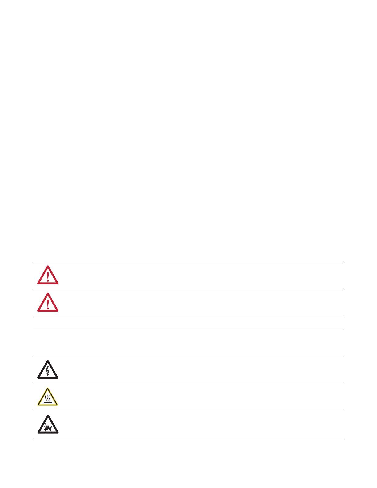
The Allen-Bradley, Bulletin 1502, 400 A vacuum contactors are designed for
applications in the 2400 and 7200V range. The contactor is suitable for all types
of AC loads, for example: three-phase motors, transformers, power capacitors
and resistive heating loads.
The contactor uses three interrupters (hereafter referred to as vacuum bottles)
operated by an electromagnet assembly through a mechanical linkage. They are
resistant to adverse atmospheric conditions and provide long mechanical and
electrical life.
The contactors are utilized in various starter and drive configurations, for
example: full-voltage non-reversing, full-voltage reversing, two-speed, reduced
voltage, synchronous, drive input/output and bypass applications. They are
generally fixed mounted within the structures and the line and load terminations
are made at the rear of the device. In most configurations, the main contactor is
mechanically interlocked with the external operating handle and isolating switch.
Bulletin 1502 vacuum contactors are designed for use with the IntelliVAC and
IntelliVAC Plus control module (refer to Publication 1503-UM053_-EN-P
and 1503-UM054_-EN-P
with an electromechanical (relay) control panel.
Bulletin 1502 electrically held and mechanical latch vacuum contactors are
provided with coils rated for 108 VDC. The IntelliVAC and IntelliVAC Plus control
module can accept a wide array of supply voltages for maximum flexibility (refer to
Publication 1503-UM053_-EN-P
). The mechanical latch contactor may also be applied
and 1503-UM054_-EN-P).
Figure 1 - 400A Contactor
Rockwell Automation Publication 1502-UM052H-EN-P - June 2013 5
Page 6
Chapter 1 Product Description
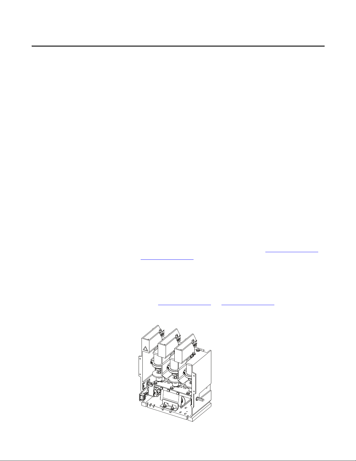
Arc Shield
Contact Wear
Indicator Line
Fixed shaft
Ceramic
Contacts
Bellows
Bearing
Movable Shaft
Vacuum Bottle Description
Each vacuum bottle (Figure 2) consists of two contacts enclosed in a ceramic
housing: an upper contact mounted to a fixed shaft, and a lower contact mounted
to a movable shaft. A stainless steel bellows ensures the vacuum integrity of the
bottle while letting the lower contact move towards and away from the fixed
contact.
Figure 2 - Vacuum Bottle Cross Section
Standard Electrically Held Contactor Operation
Each vacuum bottle (Figure 2) consists of two contacts enclosed in a ceramic
housing: an upper contact mounted to a fixed shaft, and a lower contact mounted
to a movable shaft. A stainless steel bellows ensures the vacuum integrity of the
bottle while letting the lower contact move towards and away from the fixed
contact.
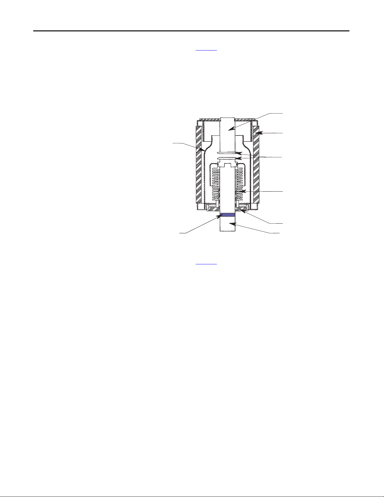
The standard electrically held contactor consists of three vacuum bottles. An
electro-magnet assembly and a mechanical linkage are used to close the contacts.
• When the IntelliVAC or IntelliVAC Plus control module receives a close
command, the contactor coils (two connected in series) are energized, and
the current creates an electromagnet with the coils.
• The electromagnet pulls the armature plate towards the coils’ core,
rotating the shaft and causing the actuator plate to move upwards.
• As the actuator plate moves, it pushes the insulator and movable shaft up,
closing the contacts in the vacuum bottle.
• The IntelliVAC or IntelliVAC Plus control module supplies the current
required to close the coils for 200 milliseconds. Afterward, the coil current
is reduced to a lower hold-in value.
• When the IntelliVAC or IntelliVAC Plus control module has the close
command removed, the coils are de-energized, opening the contactor.
6 Rockwell Automation Publication 1502-UM052H-EN-P - June 2013
Page 7
Figure 3 - Vacuum Contactor Operation
Insulator
Armature Plate & Shaft
Auxiliary Actuator
Armature Stop Bracket
Control Wire Plug
Line Terminal
Vacuum Bottle
Load Terminal
Flexible Bus
Return Spring
Actuator Plate
Gap Adjustment Screw
Magnet/Coil Assembly
C.P.T. Fuse Clip
Contactor Open
Contactor Closed
Product Description Chapter 1
Mechanically Latched Contactor Operation
The mechanically latched contactor operates in much the same way as the
electrically held (Figure 3
) with only a few exceptions.
IntelliVAC and IntelliVAC Plus Control
• Once the contactor is closed, a spring-loaded mechanism moves a roller
against the armature plate to hold it against the electromagnetic core.
• The contactor can be opened electrically by energizing a trip coil (via
IntelliVAC or IntelliVAC Plus ‘open’ [TCO] output) which pulls the
latch away from the armature, or by a push button mounted on the power
cell door that mechanically releases the contactor.
Electromechanical Control
• When the control circuit is energized, the current creates an electromagnet
in the closing coil.
• The electromagnet pulls the armature plate towards the coils’ core,
rotating the shaft and causing the actuator plate to move upwards.
• As the actuator plate moves, it pushes the insulator and movable shaft up,
closing the contacts in the vacuum bottle.
• Once the contactor is closed, a spring-loaded mechanism moves a roller
against the armature plate to hold it against the electromagnetic core.
• The control circuit economizing auxiliary contact, on the left side of the
contactor, changes from the normally closed state to the normally open
state as the contactor closes. This de-energizes the relay that controls the
closing coils.
Rockwell Automation Publication 1502-UM052H-EN-P - June 2013 7
Page 8
Chapter 1 Product Description
• The contactor can be opened electrically by energizing a trip coil which
pulls the latch away from the armature, or by a push button mounted on
the power cell door that mechanically releases the contactor.
Note : The standard mechanical latch contactor requires external 120V AC (or
DC) control relays and rectification circuit to control the standard DC closing
and trip coils on the contactor (when IntelliVAC or IntelliVAC Plus is not used).
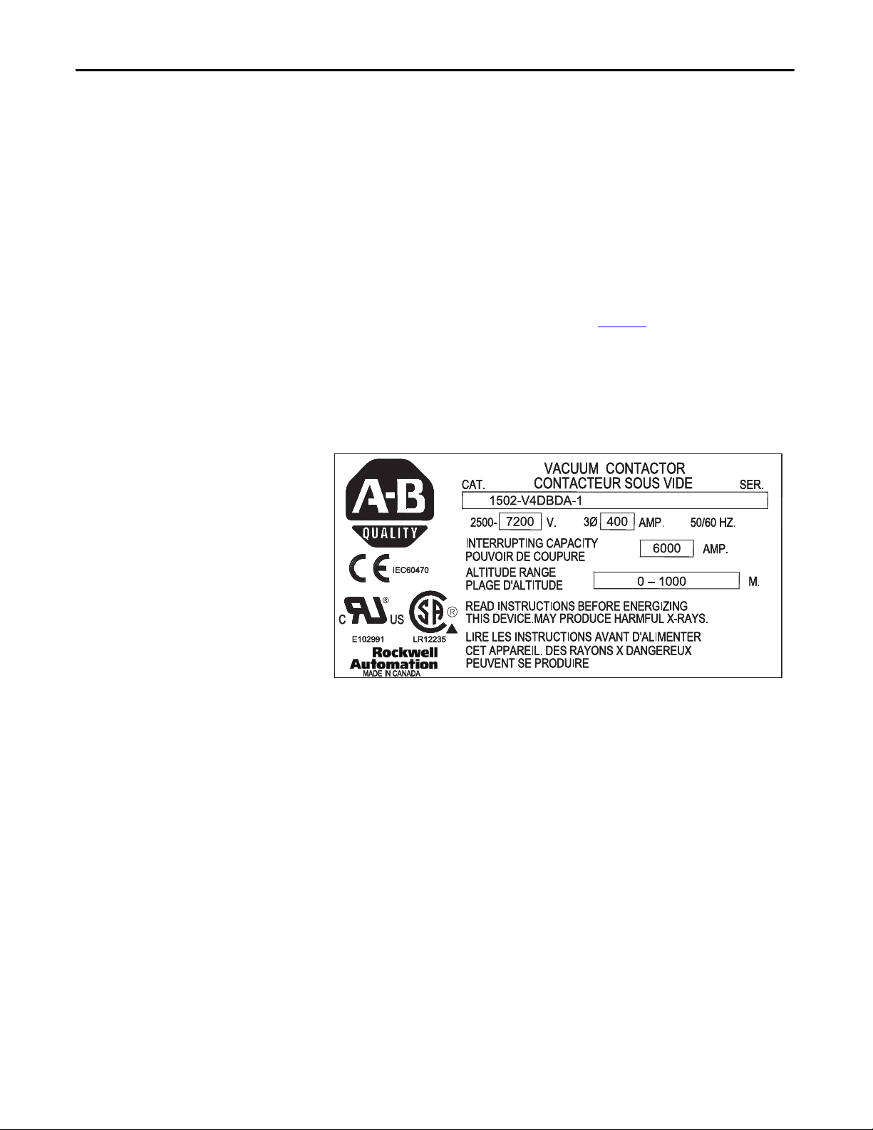
Contactor Identification
Each contactor is identified with a rating label (Figure 4) attached to the
armature plate at the front of the contactor. The rating label information
includes the Catalog Number (Cat.) Series Letter (Ser.) Voltage Rating, NonEnclosed Current Rating, Interrupting Capacity, Altitude Range (in meters),
CSA, UL and CE markings.
Figure 4 - Contactor Rating Label (400A)
8 Rockwell Automation Publication 1502-UM052H-EN-P - June 2013
Page 9
Product Description Chapter 1
1502-V4DBDA-1
First
Position
Bulletin
Number
1502
Second
Position
Contactor Type
and Interlock
V
= Vacuum,
VC
=Vacuum,
Optimized for
IntelliVAC control
Third
Position
Contactor
Size
4
= 400 A
Fourth
Position
Nominal
Line Voltage
D
= 7200 V
Fifth
Position
Fuse Mounting
Provisions
B
= 5000 V
C
= 7200 V
Sixth
Position
Coil
Voltage
D
=110VDC
Seventh
Position
Function
Refer to
TABLE
Eighth
Position
Altitude
Code (meters)
0 = -1000 – 5000
1 = 0 – 1000
2 = 1001–200 0
3 = 2001–300 0
4 = 3001–400 0
5 = 4001–500 0
E
= 207 V DC
1502-V4DBDA-1
First
Position
Bulletin
Number
1502
Second
Position
Contactor Type
and Interlock
V
= Vacuum,
VC
=Vacuum,
Optimized for
IntelliVAC control
Third
Position
Contactor
Size
4
= 400 A
Fourth
Position
Nominal
Line Voltage
D
= 7200 V
Fifth
Position
Fuse Mounting
Provisions
B
= 5000 V
C
= 7200 V
Sixth
Position
Coil
Voltage
D
=110VDC
Seventh
Position
Function
Refer to
TABLE 1
Eighth
Position
Altitude
Code (meters)
0 = -1000 – 5000
1 = 0 – 1000
2 = 1001–200 0
3 = 2001–300 0
4 = 3001–400 0
5 = 4001–500 0
E
= 207 V DC
1502-V4DBDA-1
First
Position
Bulletin
Number
1502
Second
Position
Contactor Type
and Interlock
V
= Vacuum,
VC
=Vacuum,
Optimized for
IntelliVAC control
Third
Position
Contactor
Size
4
= 400 A
Fourth
Position
Nominal
Line Voltage
D
= 7200 V
Fifth
Position
Fuse Mounting
Provisions
B
= 5000 V
C
= 7200 V
Sixth
Position
Coil
Voltage
D
=110VDC
Seventh
Position
Function
Refer to
TABLE
Eighth
Position
Altitude
Code (meters)
0 = -1000 – 5000
1 = 0 – 1000
2 = 1001–200 0
3 = 2001–300 0
4 = 3001–400 0
5 = 4001–500 0
E
= 207 V DC
Contactor Catalog Number Explanation
The following catalog number explanation is used to identify the contactor and
should be used when contacting your local Rockwell Automation Sales office, or
the factory, for assistance.
Figure 5 - Contactor Catalog Number Explanation
Table 1 - Vacuum Contactor Function
A 3 pole, electrically held contactor
B 3 pole, mechanically latched contactor with electrical and mechanical release
C 3 pole, electrically held contactor with fast drop-out
Rockwell Automation Publication 1502-UM052H-EN-P - June 2013 9
Page 10

Chapter 1 Product Description
2
Contactor Specifications
Table 2 - Bulletin 1502 Medium Voltage 400 Amp Contactor Ratings
Voltag e Ratings
Maximum Rated Voltage 7200
System Voltages 2400, 3300, 4160
Dielectric Voltage Withstand Rating For 60 seconds (kV) 18.2 / 20 (IEC)
Basic Impulse Level (B.I.L.) Withstand Phase to Ground, Phase to Phase (kV) 60
Frequency Ratings Hertz 50/60
Current Ratings
Rated Continuous Current (Amps) 400
Maximum Interrupting Current Rating 2400 V (RMS Sym Amps) 6300
Maximum Interrupting MVA Rating 2400 V (Sym MVA) 25
(1)
4800, 6600, 6900
(1)
5000 V (RMS Sym Amps) 6300
7200 V (RMS Sym Amps)
(2)
6000
5000 V (Sym MVA) 50
7200 V (Sym MVA)
(2)
75
Short-Circuit Withstand at Rated Voltage Current Peak ½ cycle (kA) 60
Short Time Current Rating Capability For 1 second (kA) 6.0
For 30 seconds (kA) 2.4
Chop Current (Average RMS Amps) 0.5
Make and Break Capability at Rated Voltage (kA) 4.0
Ambient Temperature °C 40
Contactor Coil Data
Control Voltage
)
(V
CTL
Coil Voltage (VCL)
Electro-Mechanical (Relay) Control (Mechanical Latch Only)
120 VAC 110 VDC Close Current (A
Trip Current (A
)5.6
DC
)6.0
DC
Pick-up Voltage 102
Tri p Vo lt age 84
IntelliVAC and IntelliVAC Plus Control (Electrically Held & Mechanical Latch)
110 to 240 VAC
or
110 to 250 VDC
VAC:
= X V
V
CL
(3)
(Max.)
VDC:
= V
V
CL
CTL
Close Current (ADC, 200 milliseconds) 4.3
CTL
Hold Cu rrent (A
Pick-up Voltage
Drop-out Voltage
Trip Current (A
Tri p Vo lt age
)0.48
DC
(3)
(3)
, 200 milliseconds) 5.5
DC
(3)
95
75
70
10 Rockwell Automation Publication 1502-UM052H-EN-P - June 2013
Page 11

Table 2 - Bulletin 1502 Medium Voltage 400 Amp Contactor Ratings (Continued)
Operational Characteristics
Mechanical Life (Operations) x 1000
Electrical Life (Operations) x 1000
(4)
(4)
Switching Frequenc y (O perations per hour) Electrically Held 600
Opening and Closing Times
Maximum Closing Time (120 VAC) 50 or 60 Hz (milliseconds) 160
Maximum Opening Time (120 VAC) 50 or 60 Hz (milliseconds) 50
Maximum Closing Time (50 to 60 Hz) 120 / 240 VAC (milliseconds) 100 / 70
Maximum Opening Time
(without delay, for 50 to 60 Hz)
(5)
Capacitor Switching (max. KVAR)
System Voltage 2400V 800
Electrically Held 2500
Mechanical Latch 100
1000
Mechanical Latch 150
Electro-Mechanical (Relay) Control (Mechanical Latch Only)
IntelliVAC and IntelliVAC Plus Control (Electrically Held & Mechanical Latch)
120 to 240 VAC (milliseconds) 60
4160V 1400
Product Description Chapter 1
6900V 2000
General
Standard Altitude Capability (meters / feet)
(1)(6)
-1000...5000 / 3300...16,500
Contactor Weight (kg / lbs) 21.8 / 48
Auxiliary Contact Rating A600
Auxiliary Contacts on the Vacuum Contactor (Max.)
(1) The voltage and current ratings listed are valid up to 1,000 m (3,300 ft). Please refer to Tab le 3 for ratings above this altitude.
(2) The IEC rating at 7200V (RMS Sym.) is 5300 A / 66 MVA.
(3) Control voltage, as measured at the input of the IntelliVAC or IntelliVAC Plus control module.
(4) Provided that regular maintenance is performed, as detailed in this manual.
(5) A contactor drop-out delay may be configured with the IntelliVAC or IntelliVAC Plus control module (refer to publications 1503-UM053_-EN-P
EN-P).
(6) The full Altitude range is available with the IntelliVAC or IntelliVAC Plus control module only, and the IntelliVAC or IntelliVAC Plus is to be configured accordingly (refer
to publications 1503-UM053_-EN-P
for -1000...1000 m (-3300...3300 ft). Higher altitudes are possible by changing the contactor return springs (refer to Figure 5
(7) The number of contactor auxiliary contacts depends on the contactor type. Some of the contac ts are used in the typical control schemes used.
(7)
and 1503-UM054_-EN-P). The standard mechanical latch contactors, if used with electro-mechanical control, are designed
3 N.O. / 3 N.C.
and 1503-UM054_-
for suitable catalog numbers).
Rockwell Automation Publication 1502-UM052H-EN-P - June 2013 11
Page 12

Chapter 1 Product Description
Table 3 - Altitude Derating
Altitude Rating Reduce Max. Continuous Current Rating By: Reduce B.I.L. Withstand Rating by:
400 A 800 A
0...1000 m (0...3300 ft) – – –
1001...2000 m (3301...6600 ft) 10 A 20 A 6.0 kV
2001...3000 m (6601...9900 ft) 20 A 40 A 12.0 kV
3001...4000 m (9901...13,200 ft) 30 A 60 A 18.0 kV
4001...5000 m (13,201...16,500 ft) 40 A 80 A 24.0 kV
Product Approvals
• UL347
• CSA22.2 No. 14 and T.I.L. D-21
• IEC60470
• CE Mark
12 Rockwell Automation Publication 1502-UM052H-EN-P - June 2013
Page 13

Receiving and Handling
Chapter 2
Receiving
Handling
The contactors have been tested both mechanically and electrically before leaving
the factory. Immediately upon receiving the contactor, remove the packing
material and check the contactor for possible shipping damage. If damage is
found, do not discard any of the packaging material and, if possible note the
damage on the “Bill of Lading” before accepting the shipment. Report any
damage immediately to the claims office of the common carrier. Provide a
description of the damage and as much identification as possible.
Preliminary Inspection
Check for any cracks or breaks due to impact.
Push on armature plate to ensure mechanisms are in good working order.
Use a HiPot tester to ensure vacuum bottle integrity (refer to Vac uum B ot tl e
Integrity Test on page 14).
The contactor weighs approximately 48 lb (21.8 kg) and it is possible for one
person to safely handle the contactor for a short time. When transporting the
contactor over longer distances or sustained lifting, a forklift should be
considered.
When a forklift is used to handle the equipment, the following precautions
should be taken:
• Keep the contactor in an upright position.
• Carefully balance the contactor on the forks.
• Use a safety strap to steady the contactor and avoid shifting or tipping.
• Avoid excessive speeds and sudden starts, stops and turns.
• Never lift a contactor above an area where personnel are located.
Rockwell Automation Publication 1502-UM052H-EN-P - June 2013 13
Page 14
Chapter 2 Receiving and Handling
Pre-Energization Inspection
Storage
Vacuum Bottle Integrity Test
Before placing the contactor in service, inspect it carefully for possible damage
sustained in transit or maintenance:
• Check housing for any cracks or breaks due to impact.
• Push on the armature plate and rotating shaft to ensure mechanism is in
good working order.
• Inspect the contactor for dirt, stray or loose hardware, tools or metal chips.
Vacuum clean if necessary.
If it is necessary to store the contactor before it is put into service, be certain to
store it in a clean, dry area, free from dust and condensation. Do not store
contactor outdoors.
Storage temperature should be maintained between -20...65 °C (-4...149 °F). If
storage temperature fluctuates or if humidity exceeds 85%, space heaters should
be used to prevent condensation.
The internal dielectric condition and vacuum integrity of the vacuum bottles is
determined by this test.
ATT EN TI ON : Do not apply a voltage higher than 25,000V across the open
contacts of a vacuum bottle. Dangerous x-ray emissions may be produced.
ATT EN TI ON : Vacuum bottles are thoroughly tested at the factory; however,
mishandling during shipment may cause damage. It is very important to
perform the vacuum bottle integrity test before energizing the contactor for the
first time, and before it is returned to service after maintenance or repair; test
may result in personal injury or damage to the equipment if the vacuum bottle
integrity fails.
ATT EN TI ON : High voltage testing is potentially hazardous. Use caution when
performing the Hi-pot test. Failure to do so may result in sever burns, injury or
death.
High-potential test instruments can be purchased to perform the vacuum bottle
integrity test. A Megger cannot be used to measure vacuum integrity because the
voltage is too low. One of the following AC Hi-pot testers is recommended as a
test instrument.
MANUFACTURER ADDRESS
Mitsubishi Type VI #4U17 Chicago, Ill., USA
Jennings Model JHP-70A San Jose, CA., USA
Hipotronics Model 7BT 60A Brewster, NY, USA
14 Rockwell Automation Publication 1502-UM052H-EN-P - June 2013
Page 15
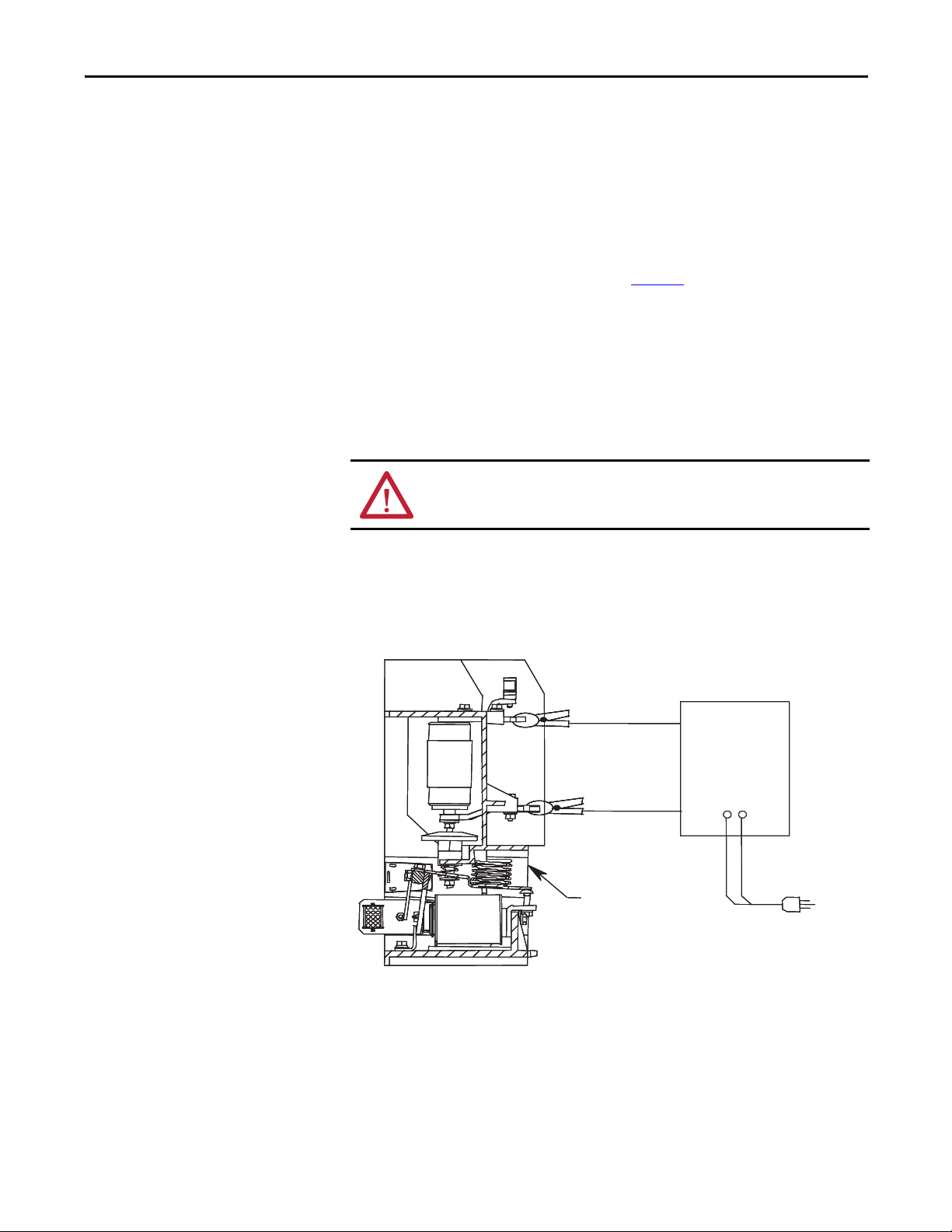
Receiving and Handling Chapter 2
Vacuum
Checker
Vacuum Contactor
in open position
1. Clean the outside of the vacuum bottles with a non-linting cloth or
industrial wipe before performing the test.
2. The contactor may be tested while it is in the power cell. The line
connection of the contactor must be disconnected and the ground lead
from the Hi-pot tester must be connected to the load side of the contactor.
Any fuses in the top of the contactor must be removed.
3. With the contactor in the open position, connect the test leads to the
contactor power terminals as shown in Figure 6
. It is recommended that an
AC Hi-pot tester be used. Apply 16 kV for 60 seconds and monitor the
leakage current. It should not exceed 5 mA. Test each vacuum bottle
individually.
4. If no breakdown occurs, the vacuum bottle is in an acceptable condition. If
a breakdown occurs, repeat the test once more. If the vacuum bottle fails a
second time, it must be replaced. If no breakdown occurs in the second
test, the vacuum bottle is in an acceptable condition.
ATT EN TI ON : If one vacuum bottle fails, Rockwell Automation recommends the
replacement of all three vacuum bottles, if the unit has been in service.
5. After the high potential voltage is removed from the vacuum bottles, the
metal end caps of the vacuum bottles should be discharged with a
grounding rod to remove any residual electrical charge.
Figure 6 - Vacuum Bottle Integrity Test Circuit
The allowable leakage current value of 5 mA is exclusive of leakage due to test
equipment leads. The test setup leakage can be determined by running the
dielectric test with test leads not connected to the contactor and noting the
maximum leakage current. If this value is more than 2 mA, it should be added to
the 5 mA limit when testing the vacuum bottles.
Rockwell Automation Publication 1502-UM052H-EN-P - June 2013 15
Page 16

Chapter 2 Receiving and Handling
Note: Rockwell Automation does not recommend DC Hi-pot testing because
the values obtained during the test may not be a reliable indication of vacuum
bottle integrity. Some specific DC “GO-NO GO” testers may provide suitable
“defective” reading s.
DC Hi-pot testing is unreliable because of a phenomenon known as Cathode Ray
Tube Effect. This occurs when one contact of the vacuum bottle has a deformity,
such as a burr or deposit, while the other contact remains flat and true. This sets
up leakage currents which flow from a small surface to a large surface in one
direction and vice versa when the polarity of the tester is changed. The resultant
current is large in one direction which would incorrectly indicate a faulty vacuum
bottle.
At best, DC testing will verify on some degree of vacuum integrity. It will not give
any indication of the degree of vacuum since the contact surface can change with
each operation of the vacuum contactor. AC testing, on the other hand, will
provide reliable vacuum integrity indication. As well, the degree of vacuum
within the bottle can be determined by comparing initial test results to the
present readings. Increases in leakage current indicate a reduction in vacuum
within the vacuum bottle.
Insulation Resistance Test
For these reasons, Rockwell Automation recommends AC testing as the best and
most reliable method of testing vacuum bottles.
A suitable GO-NO GO DC test unit is:
Manufacturer Address
Programma, Model VIDAR Santa Rosa, CA, USA
Use a 1000V Megger to verify that the resistance from phase-to-phase or phaseto-ground is greater than 500 megohms.
16 Rockwell Automation Publication 1502-UM052H-EN-P - June 2013
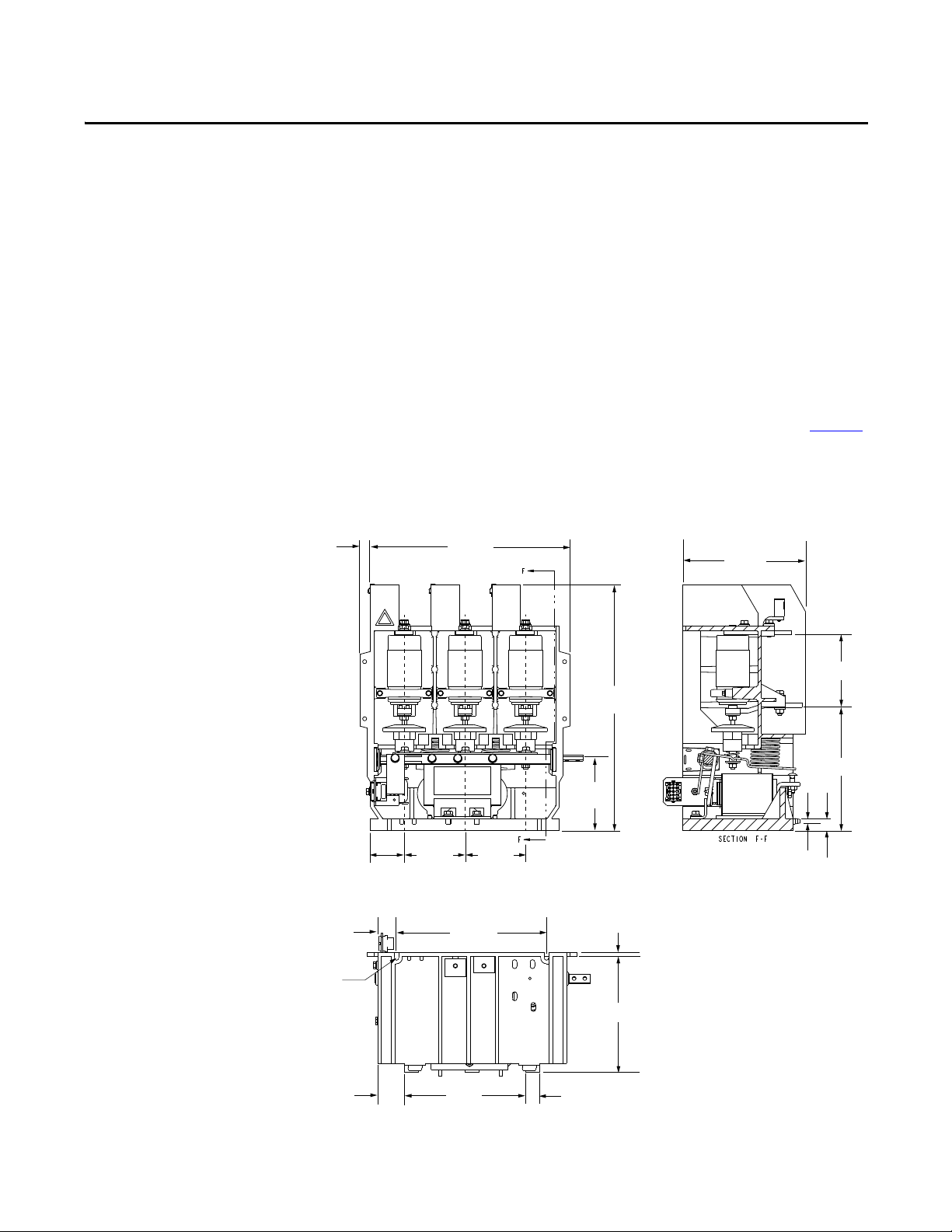
Page 17
Installation
8.64 [219]
4.96 [126]
8.53 [217]
0.37
[9]
0.91
[23]
Front View
Cut-away View
Bottom View
13.22 [336]
0.75 [19]
17.24
[438]
5.00
[127]
3.15 [80]
4.25 [108] 4.25 [108]
8.00 [203]
0.98 [25]
2.12 [54]
10.50 [267]
1.36 [35]
0.281 [7]
wide slots
7.87 [200]
0.37 [9]
Chapter 3
Mounting
The electrically held and the mechanically latched contactors are fixed mounted
(bolted down) in the controller’s cabinet. Two retaining tabs at the rear of the
contactor’s molded base can be used for mounting. The two mounting slots at the
front of the contactor’s molded base are used to secure the contactor with
1/4 in. bolts. The appropriate mounting configuration is provided inside the power cells
of Allen-Bradley controllers. If the contactor is supplied as an OEM component for
installation in a custom application, refer to the dimensional information in Figure 7
If the contactor is to be mounted in an enclosure designed by an OEM, make sure
there is a minimum of 3 in. (76 mm) of air space between live parts (terminals and
vacuum bottles) and any part of the enclosure.
Figure 7 - Contactor Mounting Details
.
Rockwell Automation Publication 1502-UM052H-EN-P - June 2013 17
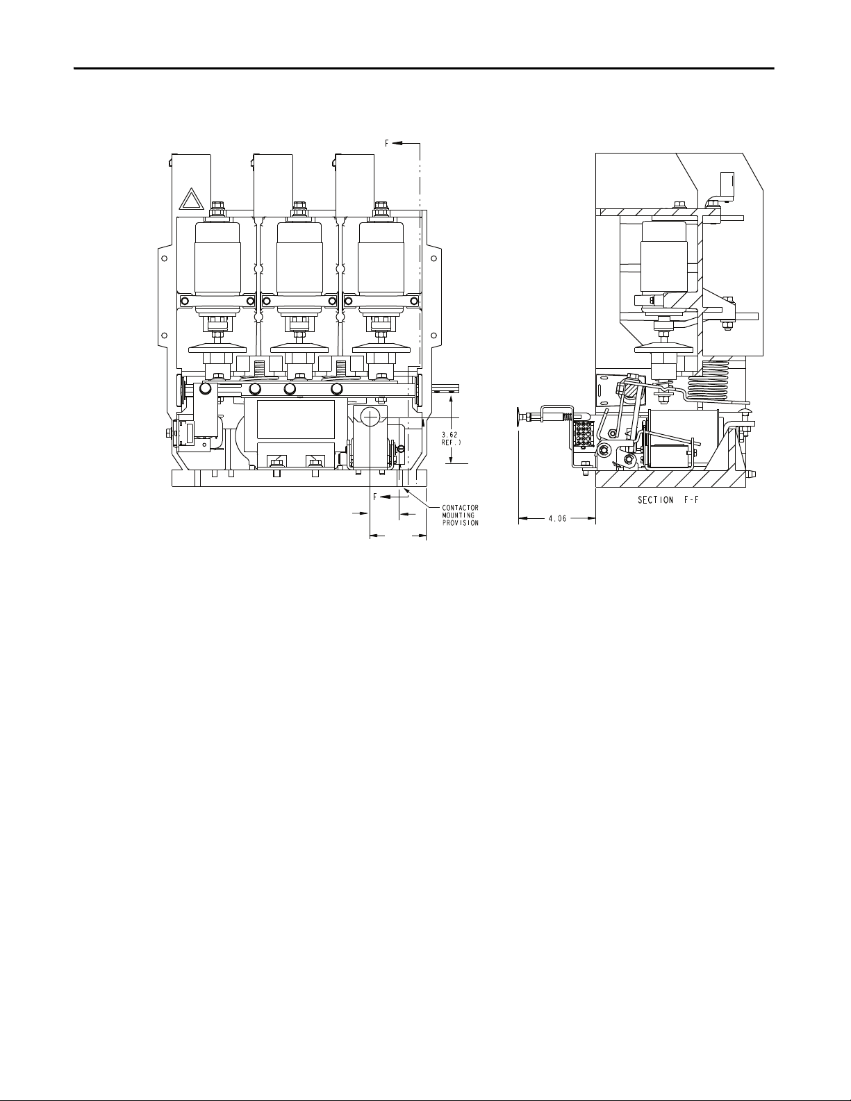
Page 18
Chapter 3 Installation
2.93
1.53
Figure 8 - Mechanical Latch Dimensions (Optional)
Electrical Connections
A wire harness connects the control wiring to the contactor from the low voltage
control panel. The harness connects to a wire plug on the lower left side of the
contactor. If the contactor is supplied as an OEM component for installation in a
custom application, the following two control options and a connecting wire
harness are available from Rockwell Automation.
• IntelliVAC and IntelliVAC Plus control modules
• Electromechanical control panel (for latch contactors only)
Connect incoming power to the line side terminals at the top, rear of the
contactor near the control fuse clips. Use 3/8 in. (10 mm) bolts torqued to
•ft (292 N•m) to secure the connection.
20 lb
Connect outgoing power to the load side terminals halfway down the rear of the
contactor. Use 3/8 in. (10 mm) bolts torqued to 20 lb
•ft (292 N•m) to secure the
connection.
For mechanically latched contactors, ensure the manual trip button in the cabinet
door is in line with the trip lever on the contactor.
18 Rockwell Automation Publication 1502-UM052H-EN-P - June 2013
Page 19

Figure 9 - Electrical Connections (Rear View)
Line Side
Terminals
Load Side
Terminals
Control Circuit Transformer
Primary Fuse Clips
Control Wire Plug
Installation Chapter 3
Rockwell Automation Publication 1502-UM052H-EN-P - June 2013 19
Page 20

Chapter 3 Installation
Wiring and Schematic Diagrams
Figure 10 - Wiring Diagram - Electrically Held Contactor (for use with IntelliVAC and IntelliVAC
Plus control modules only)
20 Rockwell Automation Publication 1502-UM052H-EN-P - June 2013
Page 21

Installation Chapter 3
Figure 11 - Wiring Diagram - Mechanical Latch Contactor (for use with IntelliVAC and IntelliVAC
Plus control modules only)
Rockwell Automation Publication 1502-UM052H-EN-P - June 2013 21
Page 22

Chapter 3 Installation
Figure 12 - Wiring Diagram - Mechanical Latch Contac tor (for use with Electro-mechanic al Control
Panel Only)
22 Rockwell Automation Publication 1502-UM052H-EN-P - June 2013
Page 23

Installation Chapter 3
Figure 13 - Wiring Diagram - Electrically Held Contactor, 120V AC (Normal Drop-out Time)
Rockwell Automation Publication 1502-UM052H-EN-P - June 2013 23
Page 24

Chapter 3 Installation
Figure 14 - Wiring Diagram - Electrically Held Contactor, 230V AC (Normal Drop-out Time)
24 Rockwell Automation Publication 1502-UM052H-EN-P - June 2013
Page 25

Installation Chapter 3
Figure 15 - Wiring Diagram - Electrically Held Contactor, 120V AC (Fast Drop-out Time)
Rockwell Automation Publication 1502-UM052H-EN-P - June 2013 25
Page 26

Chapter 3 Installation
Figure 16 - Wiring Diagram - Electrically Held Contactor, 230V AC (Fast Drop-out Time)
26 Rockwell Automation Publication 1502-UM052H-EN-P - June 2013
Page 27

Figure 17 - Wiring Diagram - Mechanically Latched Contactor (120V AC)
Installation Chapter 3
Rockwell Automation Publication 1502-UM052H-EN-P - June 2013 27
Page 28

Chapter 3 Installation
Figure 18 - Typical Electrical Diagram for 400 A Full-voltage Non-reversing (FVNR) Controller with
Electrically Held Contactor, 120V AC (Normal Drop-out Time)
28 Rockwell Automation Publication 1502-UM052H-EN-P - June 2013
Page 29

Installation Chapter 3
Figure 19 - Typical Electrical Diagram for 400 A Full-voltage Non-reversing (FVNR) Controller with
Mechanically Latched Contactor, 120V AC
Rockwell Automation Publication 1502-UM052H-EN-P - June 2013 29
Page 30

Chapter 3 Installation
TSGRD
GRD BUS
DOOR INTERLOCK
EXTRA AUXILIARY CONTACTS
MAIN CONTACTOR
"IEEE" NUMBER FOR PROTEC TIVE DEVICE
METAL OXIDE VARISTORMOV
TEST SUPPLY POINT
CUSTOMERWIRING
REFER TO DIMENSION DRAWING FOR COMPONENT SIZING NOT
NOTE:
POWER BUS
L1
L2
L3
REMOVE JUMPER WHEN CONNECTIN GREMOTE EQUIPMENT.
REMO TE EQU IPMEN T
LOW VOLTAGE DOOR MOUNTED DEVICELOW VOLTAGE DOOR MOUNTED DEVICE
ISOLATING SWITCH
50/60Hz
120V
CT1 CT2 CT3
OVERLOAD
T1
T2 T3
M
CPT
H1
H2
X1
X2
500VA ISa
57
6
49
42
44
46
47
(6)(5)
X
4.0A
(7) (8)
X
ISb
(1) (2)
(3) (4)
NORMAL
OFF
TEST
X
X
D
D
D
D
RUN
OFF
MEF
MIJ
110198
1A
2
3
1
1
34
30 31
35
OL
4
12
12
M
KLHMG
32
33 36 37
D#D
CONTACTORSTATUS - FAIL SAFE
INTELLIVAC NOTES:
MODULE STATUS - FAIL SAFE
1
14
1
2.0A
2400V-6900V 3Ø, 50/60Hz
CURRENT LIMITING
PRIMARY FUSES
CURRENT LIMITING
POWER FUSES
OL
OUTPUT RELAY CONTACTSSHOWN WITHOUTCONTROL
POWERAPPLIED. THEFOLLOWING FACTORY INSTALLED
CONFIGURATION/POWER-UP STATES ARE IN EFFECT:
INTELLIVAC TO BE PROGRAMMED/CONFIGUREDBY THE
CUSTOMER BEFORE START-UP.
M
A
15 13
B
M
MOV
20
N
17
M
C
1
32
1
EC
-
+
4
TCO
12
11
AUX CCO
5
6
L1 L2/NG
M-IV
+-
M-IV
910
CLOSE
M-IV
15 16
CONTACTOR
STATUS
START
START
STOP
STOP
1
1
Figure 20 - Typical Schematic Diagram for 400A Full-Voltage Non-Reversing (FVNR) Controller
With IntelliVAC Control and Electrically Held Contactor
30 Rockwell Automation Publication 1502-UM052H-EN-P - June 2013
Page 31

Installation Chapter 3
L1
ISOLATING SWITCH
DOOR IN TERLOCK
CURRENT LIMITING
GRDL2 L3
POWER FUSES
PRIMA RY FUSE S
CURRENT LIMI TING
VAC, 3Ø, Hz
V
VA
V
OVERLOA D
592
TEST SUPPLY POINT
MOV
V
D
D
RUN
OFF
VHz
BLK
B
W
R
TO
DEVICENET
NETWORK
+-
17
CAN H
CAN L
24V-
24V+
M-IV+V
IN 8
IN 3
IN 2
IN 1
IN 6
IN 5
IN 4
IN 7
18
19
20
21
22
23
24 COM 25
(OPTIONAL)
32
1
EC
-
+
4
TCO
12
11
AUX CCO
5
6
L1
G
SHD
COM
B
A
OUT
485
RS-
V
M-IV+
1A
M-IV+
910
CLOSE
14
14
1A
60120
TS
F3 4.0A
3534
1
IJM
31
MF
30
E
1
14A
F7
2.0A
C
M
M
17
20
13
M
15
NBA
(1) (2)
(3) (4)
NORMAL
OFF
TEST
X
X
12
12
1
6
11
7
10
8
9
ISb
(7) (8)
X
(5)(6)
X
47
46
44
42
____
120
500
CPT
__E F2__E F2
____ __
T1
T2
T3
CT3
CT2
CT1
M
F1
F1
F1
IS
ISa
5
OL49
OL D
START
V
STOP
D
M-IV
15 16
CONTACTOR
STATUS
321C
INPUT(CUSTOMERDEFINED)
INPUT(CUSTOMERDEFINED)
INPUT(CUSTOMERDEFINED)
INPUT(CUSTOMERDEFINED)
INPUT(CUSTOMERDEFINED)
INPUT(CUSTOMERDEFINED)
INPUT(CUSTOMERDEFINED)
- INTELLIVACMODULEVACUUM CONTACTORAUXILIARY INPU
T
AUX
- INTELLIVACMODULEEXTERNALCAPACITOR INPUTEC
- INTELLIVACMODULECLOSING COIL OUTPUTCCO
- MAIN CONTACTOR INTELLIVACPLUS MODULEM-IV+
- INTELLI VA C MODULETR IP COIL OUTPUTTCO
REMOTE EQUIPMENT
LOWVOLTAGEDOOR MOUNTED DEVICED
REMOVE JUMPER WHEN CONNECTING REMOTEEQUIPMENT
CUSTOMER WIRING
LEGEND
INTELLIVAC PLUS TO BE PROGRAMMED/CONFIGURED BY THE
POWER APPLIED. THE FO LLOWING FACTORY INSTALLED
OUTPUT RELAYCONTACTS SHOWN WITHOUT CONTROL
MODULE STATUS - FAIL SAFE
CONTACTOR STATUS- FAI L SAFE
CUSTOMERBEFORE START-UP.
CONFIGURATION/POWER-UP STATES ARE IN EFFE CT:
INTELLI VAC PLUS NOTES :VFAS CLO SETO INTELLIVAC PLUSAS POSSIBLE.
FERRITE CLAMP INSTALLEDON WIRES13 & 15AND 17 & 20,
F
Figure 21 - Typical Schematic Diagram for 400A Full-Voltage Non-Reversing (FVNR) Controller
With IntelliVAC Plus Control and Electrically Held Contactor (Basic)
Rockwell Automation Publication 1502-UM052H-EN-P - June 2013 31
Page 32

Chapter 3 Installation
TS
EXTRA AUXILIARY CONTACT
TEST SUPPLY POINT
50/60Hz120V
M
H1
H2
X1
X2
49
(6)(5)
X
4.0A
(7) (8)
X
ISb
(1) (2)
(3) (4)
NORMAL
OFF
TEST
X
X
110198
12
12
P
MN
34
34A
MAIN CONTACTOR
G
1
32
1
1A
3
L
M
37
M H
33
OL
OL
2
RUN
OFF
D
D
D
D
MOV
TC
MOV
CC
M
M
I
15
M-IV
32
1
EC
-
+
4
TCO
12
11
AUX CCO
5
6
13
K
19
D
17
C
21
20
M
2.0A
14
1
1
1
G
T1
T2 T3
CT3CT2CT1
42
44
46
47
OVERLOAD
OL
MANUAL
TRIP
GRD
L3
L2
L1
CURRENT LIMITING
2400V-6900V 3Ø, 50/60Hz
ISOLATING SWITCH
POWER BUS
DOOR INTERLOCK
GRD BUS
POWER FUSES
CPT
500VA
CURRENT LIMITING
PRIMARY FUSES
5
ISa
7
6
REFERTO DIMENSION DRAWING FOR COMPONENT SIZING NOT
CUSTOMER WIRING
METAL OXIDE VARISTOR
NOTE:
MOV
INTELLIVAC TO BE PROGRAMMED/CONFIGURED BY THE
CONFIGURATION/POWER-UP STATES ARE IN EFFECT:
POWER APPLIED. THEFOL LOWING FACTORY INSTALLED
OUTPUT RELAY CONTACTS SHOWN WITHOUT CONTROL
CONTACTOR STATUS - FAILSAFE
LOW VOLTAGEDOOR MOUNTED DEVICELOW VOLTAGEDOOR MOUNTED DEVICE
"IEEE" NUMBER FOR PROTECTIVE DEVICE
CUSTOMER BEFORE START-UP.
MODULE STATUS - FAIL SAFE
INTELLIVACNOTES:
D
D
#
1
TC-TRIP COIL
CLOSING COIL
TC
CC
OFF
ON
1
E
30
JM
35
M F
31
+-
+-
M-IV
78
OPEN
M-IV
910
CLOSE
A
B
1B
L1 L2/N
Figure 22 - Typical Schematic Diagram for 400A Full-Voltage Non-Reversing (FVNR) Controller
With IntelliVAC Control and Mechanical Latch Contactor
32 Rockwell Automation Publication 1502-UM052H-EN-P - June 2013
Page 33

Installation Chapter 3
TS
EXTRA AUXILIARY CONTACT
TEST SUPPLY POINT
50/60Hz120V
M
H1
H2
X1
X2
49
(6)(5)
X
4.0A
(7) (8)
X
ISb
(1) (2)
(3) (4)
NORMAL
OFF
TEST
X
X
110198
12
12
P
MN
34
34A
MAIN CONTACTOR
G
1
32
1
1A
3
L
M
37
M H
33
OL
OL
2
RUN
OFF
D
D
D
D
MOV
TC
MOV
CC
M
M
I
15
M-IV
32
1
EC
-
+
4
TCO
12
11
AUX CCO
5
6
13
K
19
D
17
C
21
20
M
2.0A
14
1
1
1
G
T1
T2 T3
CT3CT2CT1
42
44
46
47
OVERLOAD
OL
MANUAL
TRIP
GRD
L3
L2
L1
CURRENT LIMITING
2400V-6900V 3Ø, 50/60Hz
ISOLATING SWITCH
POWER BUS
DOOR INTERLOCK
GRD BUS
POWER FUSES
CPT
500VA
CURRENT LIMITING
PRIMARY FUSES
5
ISa
7
6
REFER TO DIMENSION DRAWING FOR COMPONENT SIZING NOT
CUSTOMER WIRING
METAL OXIDE VARISTOR
NOTE:
MOV
INTELLIVAC TO BE PROGRAMMED/CONFIGURED BY THE
CONFIGURATION/POWER-UP STATES ARE IN EFFECT:
POWER APPLIED. THEFOL LOWING FACTORY INSTALLED
OUTPUT RELAY CONTACTS SHOWN WITHOUT CONTROL
CONTACTOR STATUS - FAILSAFE
LOW VOLTAGEDOOR MOUNTED DEVICELOW VOLTAGEDOOR MOUNTED DEVICE
"IEEE" NUMBER FOR PROTECTIVE DEVICE
CUSTOMER BEFORE START-UP.
MODULE STATUS - FAIL SAFE
INTELLIVACNOTES:
D
D
#
1
TC-TRIP COIL
CLOSING COIL
TC
CC
OFF
ON
1
E
30
JM
35
M F
31
+-
+-
M-IV
78
OPEN
M-IV
910
CLOSE
A
B
1B
L1 L2/N
Figure 23 - Typical Schematic Diagram for 400A Full-Voltage Non-Reversing (FVNR) Controller
With IntelliVAC Plus Control and Electrically Held Contactor (with Input Examples)
Rockwell Automation Publication 1502-UM052H-EN-P - June 2013 33
Page 34

Chapter 3 Installation
TS
EXTRA AUXILIARY CONTACTS
TEST SUPPLY POINT
50/60Hz120V
M
H1
H2
X1
X2
(6)(5)
X
2.0A
(7) (8)
X
ISb
(1) (2)
(3) (4)
NORMAL
OFF
TEST
X
X
110198
12
12
12
M
IKPMN
34
34A 36 36A
REC/MOV
RECTIFIER
-
+
CR1CR1 CR1 CR1
CR2 CR2
19
17B
15A
15
17A
17
17C
M
T
TC
R
D2
CC
D1
BD
AC
M
20
MOV
MANUAL
TRIP
MAIN CONTACTOR
TC-TRIP COIL
CLOSING COIL
E
G
1
32
1
30
3
F
M
31
LM
37
M H
33
OL
M J
35
OL
2
RUN
OFF
D
D
D
D
CR1
CR2
T1 T2
CT1 CT2
T3
OVERLOAD
CT3
47
46
44
42
OL
49
L1
GRD
L3
L2
2400V-6900V 3Ø, 50/60Hz
ISOLATING SWITCH
POWER BUS
GRD BUS
CURRENT LIMITING
DOOR INTERLOCK
POWER FUSES
CURRENT LIMITING
PRIMARY FUSES
CPT
500VA ISa
5
6
7
REFER TO DIMENSION DRAWING FOR COMPONENT SI ZING NOT
CUSTOMER WIRING
METAL OXIDE VARISTOR
NOTE:
MOV
LOW VOLTAGE DOOR MOUNTED DEVICELOW VOLTAGE DOOR MOUNTED DEVICE
"IEEE" NUMBER FOR PROTECTIVE DEVICE
DD
#
TC
CC
OFF
ON
2A
MAIN CONTACTOR
LATCH RELAY
MAIN CONTACTOR
UNLATCH RELAY
Figure 24 - Typical Schematic Diagram for 400A Full-Voltage Non-Reversing (FVNR) Controller
With Electro-Mechanical Control and Mechanical Latch Contactor
34 Rockwell Automation Publication 1502-UM052H-EN-P - June 2013
Page 35

Maintenance
IMPORTANT
Chapter 4
Tool Requirements
Some components of this product incorporate Imperial hardware. Rockwell
Automation recommends the use of the appropriate tools to successfully
complete the maintenance procedure on these components. If you cannot
obtain such tools, contact your area Rockwell Automation sales office for
assistance.
When maintenance is performed on the vacuum contactor, the following tools
may be required:
• 3/8-in. drive ratchet wrench with extension
• 3/8-in. drive torque wrench
• Standard 3/8-in. drive sockets; 7/16 in., 1/2 in.
• Open end wrenches; 7/16 in., 1/2 in., 5/8 in.
• Slot head screwdrivers; 1/8-in. wide, ¼-in. wide
• External retaining ring pliers (STANLEY-PROTO #393 or equivalent)
• Feeler gauge set (0.030 in. [0.76 mm] and 0.075 in. [1.91 mm])
• Feeler gauge set (0.010 in. [0.25 mm]) Mechanical Latch
• 2-inch C-Clamp
• Armature clamping fixture (A-B Part No. 80154-149-51)
• Digital caliper capable of depth measurement
• High potential tester
Recommended Torque Values
Part of the contactor may have to be disassembled for maintenance or
replacement. There are appropriate torque requirements for particular bolt sizes
when reassembling the contactor. For the following bolt sizes, use the specified
torque values in Ta b l e 4
Table 4 - Torque Values
#10 in. Hardware
1/4 in. Hardware
5/16 in. Hardware (Grade 2)
5/16 in. Hardware (Grade 5)
3/8 in. Hardware
(1) All 5/16 hardware is Grade 2 unless otherwise specified.
(2) Refer to Figure 33.
Rockwell Automation Publication 1502-UM052H-EN-P - June 2013 35
.
2.7 lb•ft (3.6 N•m)
6 lb•ft (8 N•m)
(1)
(2)
11 lb•ft (15 N•m)
18 lb•ft (24 N•m)
20 lb•ft (27 N•m)
Page 36

Chapter 4 Maintenance
IMPORTANT
Routine Maintenance
ATT EN TI ON : Before performing any maintenance on the contactor, refer to the
User Manual of the starter configuration in which the contactor is installed for
all service instructions and procedures. Failure to do so may result in injury to
personnel or damage to the controller or contactor.
ATT EN TI ON : To avoid shock hazards, lock out incoming power and disconnect
the control plug from the contactor before working on the unit. Verify with a hot
stick or meter that all circuits are voltage free. Failure to do so may result in
severe burns, injury or death.
The following should be carried out on an annual basis or whenever a contactor is
serviced:
Cleaning
1. Ensure that metal chips or filings are cleaned from around the
electromagnet assembly (coil core pole face and mating armature plate) as
they may affect proper operation of the contactor. Vacuum clean if
necessary.
Do not use compressed air to clean or remove dirt from surfaces or the
enclosure as it will only redistribute the dirt.
2. If dirty, clean the white ceramic area of vacuum bottles with a clean lintfree cloth.
36 Rockwell Automation Publication 1502-UM052H-EN-P - June 2013
Page 37

Maintenance Chapter 4
Vacuum Bottle
Wear indicator line
on operating shaft
Main Contact Inspection
Visually inspect the wear of the main contacts with the contactor energized.
When any part of the wear indicator line, located on the front side of the shaft,
moves up into the bearing, replace all three vacuum bottles (Figure 25
Figure 25 - Vacuum Bottle Wear Indicator
).
HiPot test
Check the vacuum bottle integrity (see page 14).
Check the insulation resistance.
Lubrication
Using Aeroshell No. 7 (1 oz tube, Part No. 40025-198-01) grease the actuator
plate where the overtravel springs and washers make contact (Figure 26
).
Rockwell Automation Publication 1502-UM052H-EN-P - June 2013 37
Page 38

Chapter 4 Maintenance
IMPORTANT
Insulator
Grease
Actuator Plates
Grease
Figure 26 - Grease Locations
Do not grease the armature shaft plastic bearings. These bearings are selflubricating and do not require grease.
Vacuum Bottle Replacement and Set-Up Procedure
Under normal conditions, vacuum bottles will last at least 1,000,000 operations;
however, all three bottles must be replaced if any wear indicator line reaches the
bearing (regardless of the number of operations). Refer to FIX THIS or the part
number(s) required for this procedure.
Use the following procedure to remove and replace the vacuum bottles. This
procedure can be performed with the contactor remaining in the power cell of
the controller.
ATT EN TI ON : To avoid shock hazards, lock out incoming power and disconnect
the control plus from the contactor before working on the unit. Verify with a hot
stick or meter that all circuits are voltage free. Failure to do so may result in
severe burns, injury or death
1. Before removing the vacuum bottles, mark the installed bottles clearly to
avoid confusing them with the replacement vacuum bottles.
2. If the contactor has not been removed from the starter, first remove the
lower terminal connections at the rear of the contactor.
3. Remove the load terminal retaining bolt at the rear of the contactor, and
the vacuum bottle mounting bolt at the top of the contactor (Figure 27
).
38 Rockwell Automation Publication 1502-UM052H-EN-P - June 2013
Page 39

Maintenance Chapter 4
Vacuum Bottle
Mounting Bolt
Load Terminal
Retaining Bolt
and Hardware
Insulator Stud
Load Terminal Nut
Figure 27 - Mounting and Retaining Bolt Removal
4. Loosen the load terminal nut on one bottle assembly, tilt the bottle
forward (out of the contactor) and unscrew it from the insulator stud as
shown in Figure 28
. Repeat this for the two remaining bottles. The load
terminals, insulators and overtravel spring assemblies remain in the
contactor as shown in Figure 28
.
Figure 28 - Removal of Vacuum Bottles
5. Install a new bottle by tilting an insulator forward and threading the bottle
onto the stud (reverse of Step 3). Take care to ensure the threads are
aligned as cross-threading can occur. Thread the bottle down, leaving a gap
of approximately 4.82 mm ± 0.25 mm (0.190 in. ± 0.01 in.) between the
top of the bottle and the bottom surface of the line terminal, as show in
Figure 29
. Use inside calipers and micrometer, or another accurate
measuring tool, to set the gap. This gap is precisely calibrated later in this
section. The wear indicator line on the bottom of the bottle’s movable
shaft must be facing forward (i.e. visible from the front of the contactor).
Repeat this step for the remaining two bottles.
Rockwell Automation Publication 1502-UM052H-EN-P - June 2013 39
Page 40

Chapter 4 Maintenance
0.190 in. [4.82 mm]
Vacuum Bottles
Insulator
Overtravel Gap
0.065 in. [1.65 mm]
Figure 29 - Establishing Contact Gap
6. Install the load terminal retaining bolts at the rear of the contactor. Leave
the load terminal nuts loose for fine adjustment of the overtravel and
contact gap. Install the vacuum bottle mounting bolts at the top of the
contactor (reverse of step 2). Take care to ensure the threads are aligned as
cross-threading can occur. Hold the bottle to prevent it from turning while
torquing the vacuum bottle mounting bolts.
7. Close the contactor by using the TEST control circuit in the starter. Insert
a feeler gauge of 0.065 in. (1.65 mm) into the overtravel gap of a bottle
assembly (Figure 30
). Rotate the insulator until the gap is correctly set.
Repeat this step for the two remaining bottles. This step must be
performed accurately because it establishes synchronization between the
three vacuum bottles.
Figure 30 - Establishing Overtravel
8. With the contactor still energized, measure dimension A1 for all three
bottles (Figure 31
). De-energize (drop out) the contactor and measure
dimension A2 for all three bottles. The contact gap is the difference of A2
minus A1. Record the gap for all three bottles.
40 Rockwell Automation Publication 1502-UM052H-EN-P - June 2013
Page 41

Maintenance Chapter 4
A1
A2
Figure 31 - Measuring Contact Gap
9. The contact gaps must be synchronized within 0.02 in. (0.5 mm). If the
gaps are not synchronized, rotate the insulators as required to achieve this.
Make sure the overtravel remains a minimum of 0.065 in. (1.65 mm) on
each bottle.
10. Tighten the load terminal nut on each bottle assembly. To do this without
damaging the bellows, apply wrenches to the load terminal nut and to the
flattened section of the movable bottle shaft. Tighten the load terminal
nut while holding the bottle shaft steady. Be careful not to turn the
insulator as this will change the gap.
11. The final contact gap for all three bottles must be between 0.180 in. and
0.200 in. (4.57 mm and 5.08 mm). If this is the case, the replacement
procedure is complete. If further adjustment is required, all three gaps can
be adjusted simultaneously by loosening the stop bracket bolts and
adjusting the height of the gap adjustment screw at the rear of the
contactor as shown in Figure 32
. To adjust the height of the screw, first
loosen the locking nut.
12. When the gap is correct, tighten the gap adjustment screw locking nut.
Position the stop bracket lightly against the armature plate and tighten the
bolts securing the stop in position. Make sure that the actuator plate
contacts the gap adjustment screw and the armature plate contacts the stop
bracket as shown in Figure 32
.
Rockwell Automation Publication 1502-UM052H-EN-P - June 2013 41
Page 42

Chapter 4 Maintenance
Stop Bracket Bolts
Gap Adjustment Screw
Gap Adjustment Screw
Locking Nut
Stop Bracket
Figure 32 - Contact Gap Adjustment
Coil Replacement Procedure
ATT EN TI ON : To avoid shock hazards, lock out incoming power and disconnect
the control plug from the contactor before working on the unit. Verify with a hot
stick or meter that all circuits are voltage free. Failure to do so may result in
severe burns, injury or death.
Refer to Chapter 6 for the part number(s) required for this procedure.
1. Remove the auxiliary actuator, front stop bracket and armature plate as
shown in Figure 33
.
Do not remove the bolts which secure the stop bracket, simply loosen them
and slide the bracket out.
42 Rockwell Automation Publication 1502-UM052H-EN-P - June 2013
Page 43

Maintenance Chapter 4
Auxiliary Actuator
Stop Bracket Bolts
Armature Stop Bracket
Armature Plate
Return Spring Actuator Plate
Grade 5 (5/16 Hardware) to mount
return spring actuator plate. Refer
to page 4-1 for torque values.
Grade 5 (5/16 Hardware) to mount
armature plate. Refer to page 4-1
for torque values.
Auxiliary Assembly
Retaining Bolt
Operating Coil
Operating Coil
Retaining Ring
Auxiliary Assembly
Figure 33 - Access to Coils
2. Remove the retaining ring from the core of the coil you wish to replace as
shown in Figure 34
.
3. Loosen the auxiliary assembly retaining bolt and slide the assembly and the
coils forward and out of the contactor as shown in Figure 34
Figure 34 - Coil Removal
.
4. Disconnect the coil leads (take note of their location). Connect the leads
of the new coil making sure that all metal-oxide varistors (MOVs) and/or
diodes are secure. Refer to the appropriate wiring diagram in this manual if
further control wiring details are required (see page 20
5. Slide the new coil into position and install the retaining ring on the core.
).
Install the auxiliary assembly leaving the retaining bolt loose for adjustment
later. See the Auxiliary Contact Set-up Procedure (page 4-10) for
determining the position of the auxiliary assembly.
Rockwell Automation Publication 1502-UM052H-EN-P - June 2013 43
Page 44

Chapter 4 Maintenance
IMPORTANT
Auxiliary Actuator
Armature Plate
Armature Stop Bracket
6. Install the armature plate, auxiliary actuator and stop bracket. Position the
stop bracket by resting it lightly against the armature plate.
This procedure applies to adjustment of existing auxiliaries and installation of
new auxiliaries. Under normal conditions, auxiliaries will last at least
1,000,000 operations. If auxiliary contacts must be replaced, discard the entire
assembly and install a new assembly. This is easier than replacing a single
contact block.
Auxiliary Contact Set-up Procedure
Refer to Chapter 6 for part number(s) required for this procedure.
To facilitate the set-up procedure, the contactor is held closed mechanically by
means of a clamping fixture as shown in Figure 4.13. It is important that the
contactor is held closed tightly with the armature plate against the magnet cores
when gauging the overtravel and auxiliary positioning.
To aid in closing the contactor mechanically, a clamping fixture is required. AllenBradley part number 80154-149-51 is recommended.
Figure 35 - Contactor Components
1. Loosen the nuts on auxiliary assembly retaining bolt. This requires
loosening and removal of the first nut which secures a ground wire at this
location. Leave on nut loosened just enough to permit the assembly to
slide along the adjustment slot as shown in Figure 36
44 Rockwell Automation Publication 1502-UM052H-EN-P - June 2013
.
Page 45

Maintenance Chapter 4
Auxiliary Assembly
Retaining Bolt
Contactor Clamping Fixture
Figure 36 - Auxiliary Contact Adjustment
2. Slide the clamping fixture (part number 80154-149-51) over the top of the
armature stop bracket (Figure 37
). Finger-tighten the two outside fixture
mounting bolts against the armature stop bracket. You may have to push
the armature plate a little to the rear to put the clamp in place.
Figure 37 - Clamping Contactor Closed
3. Place a 5/8” wrench on the main shaft of the contactor, pull down and
close the contactor (Figure 38
) while finger-tightening the top middle
screw on the clamping fixture. (Case should be taken not to bend the
actuator stop plate).
Rockwell Automation Publication 1502-UM052H-EN-P - June 2013 45
Page 46

Chapter 4 Maintenance
Figure 38 - Closing the Contactor
4. After the top screw is finger tight, continue to tighten this screw with a
hand tool. The armature stop bracket will flex a little; this is acceptable but
do not over-tighten and bend the armature stop plate. It is important that
the armature plate is held tightly against the magnet cores. The contactor
must be fully closed.
5. Place a wide blade 0.030 in. (0.76 mm) feeler gauge between the plastic
auxiliary actuator tips and the steel actuator plate. To aid the installation of
the feeler gauge, the gauge can be put in place as the clamping block screw
is being finger-tightened (Step 3). Reference Figure 39
Figure 39 - Gauging the Contacts
and Figure 40.
46 Rockwell Automation Publication 1502-UM052H-EN-P - June 2013
Page 47

Maintenance Chapter 4
IMPORTANT
Put feeler gauge here
0.030 in. [0.76 mm]
Auxiliary Actuator Bolt
Figure 40 - Gauging Auxiliary Contact Location
6. With the gauge in place, slide the assembly forward until the contact
actuator bottoms out. With the gauge still in place, carefully tighten the
auxiliary assembly retaining nut.
Always use a wrench to hold the bolt head as you tighten the nut. Make sure
the auxiliary assembly does no move as you tighten the nut.
7. When the first nut is tightened, slide out and remove the feeler gauge.
8. Reinstall the green ground wire on the auxiliary assembly retaining bolt.
Install and carefully tighten the second nut.
9. Slowly loosen the top screw of the contactor clamping fixture to remove
the pressure on the armature plate. Loosen the two mounting screws on the
contactor clamping fixture. Remove the fixture.
10. Energize the control circuit in “TEST” mode and exercise the contactor to
verify set-up. Contactor should open and close smoothly and solidly.
Rockwell Automation Publication 1502-UM052H-EN-P - June 2013 47
Page 48

Chapter 4 Maintenance
Latch Coil Wires
Mechanically Latched Contactor Trip Coil Replacement Procedure
Parts
Refer to Chapter 6 for the part number(s) required for this procedure.
• Required Tools
• Two 7/16” Wrenches
• 3/8 socket and ratchet
• 5/16 socket and ratchet
• Phillips Screwdriver
• 3/32” Right Angle Allen Key
• Feller gauges
• Side Cutting Pliers
• Wire Ties
• Armature Clamping Fixture, 80154-149-51
Procedure
1. Cut wire ties at the rear of the contactor holding the mechanical latch coil
wires in place (Figure 41
).
Figure 41 - Rear View of Mechanical Latch Contactor (showing wires to trip coil)
48 Rockwell Automation Publication 1502-UM052H-EN-P - June 2013
Page 49

Maintenance Chapter 4
Actuator Plate
Auxiliary Contact
Assembly
Retaining Bolt
2. Using ½” wrench, remove the auxiliary contact actuator plate form the
main shaft assembly (Figure 42
Figure 42 - Auxiliary Actuator Plate Removal
).
3. Using two 7/16” wrenches, loosen the auxiliary contact assembly retaining
bolt and slide the auxiliary contact assembly out of the front of the
contactor (Figure 43
).
Figure 43 - Auxiliary Contact Assembly Removal
4. Disconnect the mechanical latch trip coil leads form the auxiliary contact
assembly using a Phillips screwdriver.
5. Using a 3/8” socket, remove the ¼-20 hardware holding the mechanical
trip mechanism in place, and then remove the mechanical trip mechanism
(Figure 44
).
Rockwell Automation Publication 1502-UM052H-EN-P - June 2013 49
Page 50

Chapter 4 Maintenance
Mechanical Trip
Mechanism
¼-20 Hardware
(Qty 2)
Contactor
Return Spring Seat
Shaft
“E” Clip and Washer
Latch Lever Assembly
Guide/Stop Plate
#10-32 Hardware
Figure 44 - Removal of Mechanical Trip Mechanism
6. Remove the “E” clip and washer from the latch lever assembly shaft and
then remove the shaft (Figure 45
). Remove the latch lever assembly from
the mechanical latch base. Note that the return spring is “seated” on the
right side of the mechanical latch base. (Note: Contactor not shown for
clarity).
Figure 45 - Removal of Latch Lever Assembly
50 Rockwell Automation Publication 1502-UM052H-EN-P - June 2013
Figure 46 - Removal of Guide/Stop Plate
7. Using a 5/16” socket, remove the #10-32 hardware holding the stainless
steel guide/stop plate in place, and then remove the guide/stop plate
(Figure 46
). (Note: Contactor not shown for clarity).
Page 51

Maintenance Chapter 4
Flapper
Step 1:
Slide flapper to right.
Step 2:
Pull flapper forward to remove.
Magnet Coil
Coil Core
Use right angle Allen key
to remove coil core
8. Remove the flapper by sliding it to the right until it stops and then pulling
it towards the front of the contact (Figure 47
). The trip (magnet) coil and
coil core are now exposed (Note: Contactor not shown for clarity).
Figure 47 - Removal of Flapper
9. Using a right angle Allen key, remove the coil core (Figure 48) and trip
(magnet) coil (No te: Contactor not shown for clarity).
Figure 48 - Trip Coil and Core Removal
10. Slide the coil core from the trip (magnet) coil and then place the
11. Connect the new trip (magnet) coil leads to the auxiliary contact assembly.
12. Re-assemble the mechanical latch and auxiliary assembly in reverse order
13. Perform the auxiliary contact assembly adjustment procedure (see
14. Verify that the replacement trip coil functions by using Test Power to close
Rockwell Automation Publication 1502-UM052H-EN-P - June 2013 51
replacement coil onto the coil core.
of this procedure.
page 44
). Note: The contactor will not function correctly if this step is not
performed.
(latch) the contactor. Complete the cycle by opening (tripping ) the
contactor. Perform this sequence 2-3 times to ensure that the contactor
closes (latches and opens (trips) properly.
Page 52

Chapter 4 Maintenance
Mechanically Latched
Contactor Clamping Fixture
0.010 in. [0.25 mm]
Insert feeler gauge here
Mechanically Latched Contactor Set-up Procedure
1. The overtravel, contact gap and auxiliary set-up procedures are the same
for mechanically latched contactors as they are for electrically held
contactors except that instead of energizing the contactor with the
“TEST” circuit, the contactor must be held closed mechanically by means
of a clamp or special fixture as shown in Figure 4.25. It is important that
the contactor is held closed tightly with the armature against the magnet
cores when gauging the overtravel, contact gap and auxiliary positioning.
Allen-Bradley part number 80154-149-51 is recommended, however, a Cclamp can be used at the rear of the contactor to pull up the actuator plate
(care must be taken not to overtighten the C-clamp and bend the actuator
plate).
Figure 49 - Clamping a Mechanically Latched Contactor Closed
2. Clamp the contactor closed as detailed in Step 1. The latch mechanism
should be in place with the mounting bolts loose enough to allow sliding
along the adjustment slots.
3. With the contactor lying on its back, insert a .015 in. (0.38) feeler gauge
between the latch roller and the armature plate as shown in Figure 50
Tighten the mounting blots (do not overtorque 1/4 inch nuts or 5/16 in
bolts).
Figure 50 - Gauging Mechanical Latch Location
.
52 Rockwell Automation Publication 1502-UM052H-EN-P - June 2013
Page 53

Maintenance Chapter 4
IMPORTANT
IMPORTANT
4. With the contactor still clamped, depress the latch lever and release
allowing it to spring up. Ensure smooth, unimpeded motion.
5. Remove the clamp and allow the armature to move out against the roller
such that the contactor is in the “latched” condition.
ATT EN TI ON : The return springs exert a significant force on the armature plate.
To avoid injury, do not place fingers between the armature plate and the stop
bracket at any time.
6. Using the manual trip lever, trip (drop out) the contactor. Apply 2 to 3 lb.
of force to trip the contactor. If too little force is required, the mechanism
must be moved away from the armature slightly (toward the front of the
contactor). If too great a force is required, the mechanism must be moved
toward the armature slightly (toward the back of the contactor). If
adjustment is required, the contactor must be clamped closed and the setup procedure repeated with thicker or thinner feeler gauges as required.
This is a sensitive and critical set-up. A few thousandths of an inch makes a
noticeable difference in the function of the latch. A mechanism which trips too
easily may result in nuisance tripping. A mechanism which requires too much
force may result in failure of the coil to trip the latch.
Altitude Adjustment
Altitude will affect the performance of a vacuum contactor. Atmospheric pressure
assists in closing the main contacts by exerting force on the bellows at the
movable end of the vacuum bottles. The force is proportional to the difference
between the internal bottle pressure and external atmospheric pressure and
adjustments to the operating mechanism must be made to balance the change in
closing force. The 400A contactors are equipped with return springs appropriate
for the specific altitude they will be operating at.
Note: IntelliVAC vacuum contactors typically use the bronze-colored return
springs, and the IntelliVAC and IntelliVAC Plus control modules are used to
compensate. If a mechanical latch contactor is applied without IntelliVAC or
IntelliVAC Plus control, the springs must be changed. (Electrically held
contactors (Series E or later) may only be used with IntelliVAC control. Refer to
publication 1503-UM053_-EN-P
Do not change springs on contactors whose catalog number end in ‘-0’.
If a relay controlled latch contactor is to be moved to a different altitude, refer to
Ta b l e 5
replace the springs and correct the rating label information (catalog number,
altitude range and current rating) per Ta b l e 5
Rating (B.I.L) as it relates to altitude.
to determine the correct return springs for the new altitude range. Simply
or 1503-UM054_-EN-P).
. Note the change Basic Impulse
Rockwell Automation Publication 1502-UM052H-EN-P - June 2013 53
Page 54

Chapter 4 Maintenance
IMPORTANT
Table 5 - Altitude Range Spring Requirements, 400A Mechanical (relay control only)
Altitude Range Spring Part No. Color Code Continuous
Current Rating
0...1000 m 80153-567-01 Bronze 400 A 60 kV
1000...2000 m 80026-007-02 Green 390 A 54 kV
2000...3000 m 80026-008-02 Blue 380 A 48 kV
3000...4000 m 80026-009-02 Black 370 A 42 kV
4000...5000 m 80026-010-02 Olive 360 A 36 kV
B.I.L. Rating
A contactor will only function properly in the altitude range for which it is set
up. If functional tests are required, they must be performed at the proper
altitude or in a pressure chamber which simulates the proper altitude.
54 Rockwell Automation Publication 1502-UM052H-EN-P - June 2013
Page 55

Troubleshooting
Chapter 5
Troubleshooting and Contactor Coil Resistance
If an operating problem occurs, use the following troubleshooting chart to isolate
the cause of the failure and find corrective action. If the corrective action fails to
resolve the problem, consult your local Rockwell Automation field support
representative.
Table 6 - Troubleshooting
Symptom Possible Cause Actions
Contactor Chatte rs
Coil Burn out • Coil leads improperly wired
Contactor does not energize • Loose connections in control circuit
(1)
• Loose connections in control circuit
• Coil leads reverse d
• Control voltage too low
• Foreign material on contactor magnet
• Improper set-up of contactor auxiliary contact
assembly
• Faulty auxiliary contacts
• Faulty CR1 or CR2 interposing relay (mechanical latch
only)
• Faulty IntelliVAC or IntelliVAC Plus
• Latch not engaging
• Faulty IntelliVAC or IntelliVAC Plus control module
• Improper set-up of contactor auxiliary contact
• Control voltage too high
• Damaged contactor auxiliary contacts
• Control voltage too low
• Improper set-up of contactor auxiliary contact assembly
• Faulty CR1 or CR2 interposing relay
• Faulty IntelliVAC or IntelliVAC Plus control module
assembly
(1)
(2)
(1)
(2)
(2)
• Check all connections in contro l circuit for tightness
• Check wiring from the coil to the terminal block
• Measure control voltage. Refer to Contactor
• Clean magnet cores and armature
• Check set-up of contactor auxiliary contact assembly.
• Check master contact cartridges on contactor
• Ensure N.C. contact from contactor auxiliar y assembly
• Replace IntelliVAC or IntelliVAC Plus control module
• Check adjustment of mechanical latch
• Check wiring from the coil to the terminal block
• Replace IntelliVAC or IntelliVAC Plus control module
• Check set-up of contactor auxil iary contact assembly
• Check for correct control voltage
• Check all connections in control circuit for t ightness.
• Replace contactor auxiliary contact assembly
• Measure control voltage. Refer to Contactor
• Check set-up of contactor auxiliary contact assembly
• Check CR1 and CR2 relay
• Check IntelliVAC or IntelliVAC Plus status LEDs
assembly
Specifications for minimum pick-up voltage
is wired to auxiliary input on IntelliVAC or IntelliVAC
Plus
assembly
(1)
Check wiring from the coil to the terminal block
assembly
specifications for minimum pick-up voltage
(1)
(2)
(2)
(1)
(1) Valid if mechanical latch contactors are controlled with electromechanical circuit only.
(2) Valid if IntelliVAC or IntelliVAC Plus control module is used (refer to 1503 -UM053_-EN-P
If faulty contactor coil(s) are the suspected cause of malfunction, refer to Ta b l e 7
for typical coil resistance values and check the contactor coils.
Table 7 - Typical Contactor Coil Resistance Values
Coil Part Number Description DC resistance (Ω)
80026-230-01 Operating Coil (each) 19.2 (9.6 x 2)
80022-067-01
(1) Resistance values listed have a tolerance of ±10%. Refer to page 17 for measurement points at the contactor receptacle.
(2) Supplied only with mechanical latch option.
Rockwell Automation Publication 1502-UM052H-EN-P - June 2013 55
(2)
and 1503-UM054_-EN-P).
(1)
Mechanical Latch Trip Coil 17.6
Page 56

Chapter 5 Troubleshooting
Notes:
56 Rockwell Automation Publication 1502-UM052H-EN-P - June 2013
Page 57

Spare Parts
Vacuum Bottles
Coil Retaining Ring
Auxiliary Actuator Plate
Auxiliary Assembly
Stop Bracket
Armature Plate
Coil
Auxiliary Assembly
Return Spring
Bottle Clamp
Mechanical Latch
Trip Coil
Chapter 6
Bulletin 1502 Spare Parts Diagrams and Chart
Figure 51 - Bulletin 1502, 400A Electrically Held Vacuum Contactor
Figure 52 - Bulletin 1502, 400A Mechanical Latch Assembly
Latch Lever Assembly
Rockwell Automation Publication 1502-UM052H-EN-P - June 2013 57
Page 58

Chapter 6 Spare Parts
Table 8 - Spare Parts
Item Description of Parts
120V Control
1Three Vacuum Bottles
(1)
Part Number
400A
80157-496-52
2 Main Coils (Qty. 2) 80026-230-01
3Auxiliary Assemblies
(2)
Electrically held 80158-743-52
Mechanical latch IntelliVAC or IntelliVAC Plus
80158-744-52
Control
Electromechanical Control 80153-999-60
4 Mechanical Latch Trip Coil (120 VAC) 80022-067-01
5 Return Spring (standard altitude 0...1000 m)
(3)
80153-567-01
6 Coil Retaining Ring 28325-042-01
7 Stop Bracket 80153-565-01
8 Auxiliary Actuator Plate 80153-553-02
9 Armature Plate 80153-552-02
10 Latch Lever Assembly 80158-768-51
11 Bottle Clamp (Qty. 3) PN-129674
(1) Rockwell Automation recommends that if the contactor has been in service, all three (3) bottles be replaced at the same time.
(2) The auxiliary assemb lies include contact blocks, wire harness, female connector and mounting bracket.
(3) Refer to Table 5 on page 54
for Return Spring part number for higher altitude contactors (if mechanical latch contactors are used without IntelliVAC or IntelliVAC Plus control).
58 Rockwell Automation Publication 1502-UM052H-EN-P - June 2013
Page 59

Page 60

Rockwell Automation Support
Rockwell Automation provides technical information on the Web to assist you in using its products.
At http://www.rockwellautomation.com/support
code and links to software service packs, and a MySupport feature that you can customize to make the best use of these
tools. You can also visit our Knowledgebase at http://www.rockwellautomation.com/knowledgebase
information, support chat and forums, software updates, and to sign up for product notification updates.
, you can find technical manuals, technical and application notes, sample
for FAQs, technical
For an additional level of technical phone support for installation, configuration, and troubleshooting, we offer
SM
Te c h C o n n e c t
representative, or visit http://www.rockwellautomation.com/support/
support programs. For more information, contact your local distributor or Rockwell Automation
.
Installation Assistance
If you experience a problem within the first 24 hours of installation, review the information that is contained in this
manual. You can contact Customer Support for initial help in getting your product up and running.
United States or Canada 1.440.646.3434
Outside United States or Canada Use the Wor ldwid e Loc ator at http://www.rockwellautomation.com/rockwellautomation/support/overview.page, or contact your local
Rockwell Automation representative.
New Product Satisfaction Return
Rockwell Automation tests all of its products to help ensure that they are fully operational when shipped from the
manufacturing facility. However, if your product is not functioning and needs to be returned, follow these procedures.
United States Contact your distributor. You must provide a Customer Support case number (call the pho ne number above to obtain one) to your
Outside United States Please contact your local Rockwell Automation representative for the return procedure.
distributor to complete the return process.
Documentation Feedback
Your comments will help us serve your documentation needs better. If you have any suggestions on how to improve this
document, complete this form, publication RA-DU002
Medium Voltage Products, 135 Dundas Street, Cambridge, ON, N1R 5X1 Canada, Tel: (1) 519.740.4100, Fax: (1) 519.623.8930
Online: www.ab.com/mvb
Allen-Bradley, Rockwell Software, Rockwell Automation, and TechConnect are trademarks of Rockwell Automation, Inc.
Trademarks not belonging to Rockwell Automation are property of their respec tive companies.
Publication 1502-UM052H-EN-P - June 2013
Supersedes Publication 1502-UM052G-EN-P - November 2012 Copyright © 2013 Rockwell Automation, Inc . All rights reserved. Printed in Canada.
, available at http://www.rockwellautomation.com/literature/.
 Loading...