

Page 1
FLEX I/Ot SCANportt Module
(Cat. No. 1203FM1)
Installation Instructions
1
7
0
1
8
2
3
6
4
6
Channel 1 Channel 2
S
5
2
3
4
Module
Installation
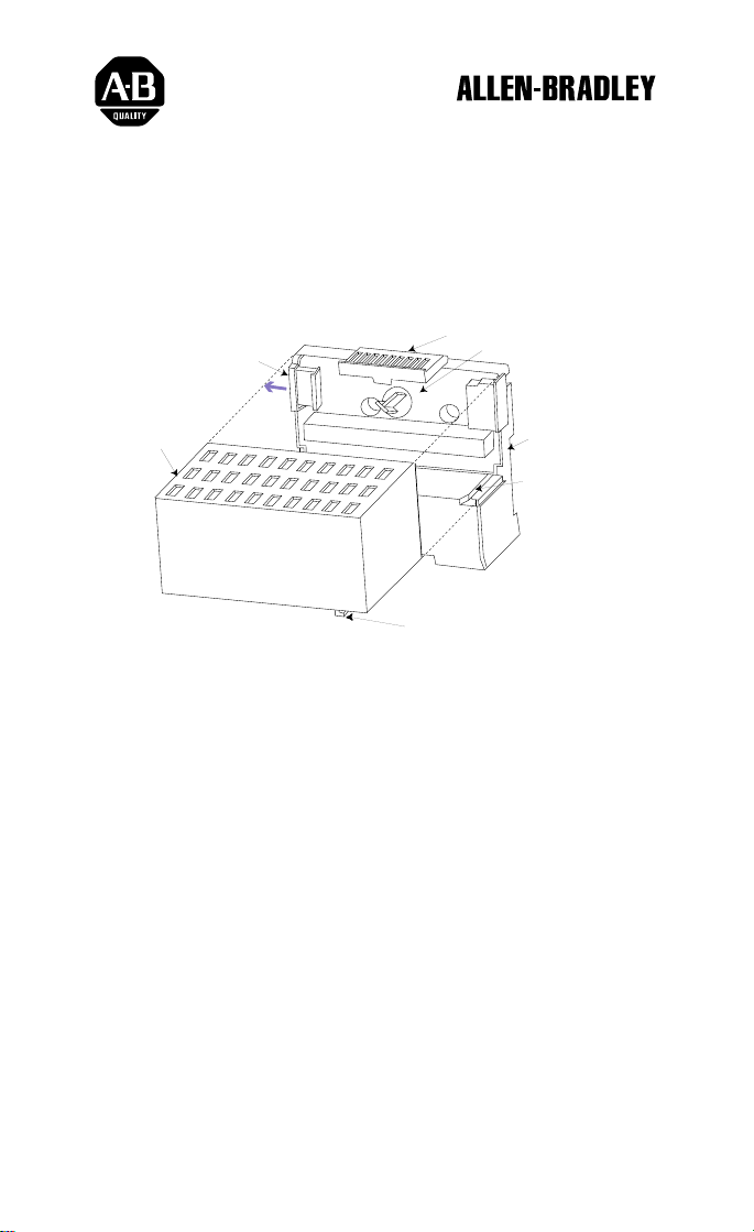
Important: This module mounts on a special 1203 terminal base unit and should
not be used with any other flex base. You can remove and insert
modules under power. However, removal may cause the attached
SCANport device(s) to fault.
To mount this module, you need to:
FLEX I/O is a trademark of AllenBradley Co. Inc.
SCANport is a trademark of Allen-Bradley Co. Inc.
Page 2
1–2
FLEX I/O SCANportt Module Installation Instructions
1. Rotate keyswitch (2) on terminal base unit (3) clockwise to
position 1 as required for this type of module.
2. Make certain the flexbus connector (7) is pushed all the way to
the left to connect with the neighboring terminal base/adapter.
You cannot install the module unless the connector is fully
extended.
3. Make sure that the pins on the bottom of the module are straight
so they will align properly with the connector in the terminal
base unit.
4. Position the module (6) with its alignment bar (5) aligned with
the groove (4) on the terminal base.
5. Press firmly and evenly to seat the module in the terminal base
unit. The module is seated when the latching mechanism (1) is
locked into the module.
6. Repeat the above steps to install the next module in its terminal
base unit.
ATTENTION: The 1203–FM1 may require up to twice the adapter
power supply current of standard flex modules. When installing flex
!
modules, you can use a maximum of four 1203–FM1 modules with any
flex adapter. As a general rule, each 1203–FM1 requires the power
capacity of two of the standard flex modules, so you cannot install as many
standard modules as you normally would when using the 1203–FM1.
Refer to the following chart to determine the number of 1203 and standard
modules that may be installed together in your system.
If you are using this
number of standard
(1794) modules:
7 or 8
5 or 6
3 or 4 2 4
1 or 2 3 6
1203-5.7-- April 1996
Then, the maximum
number of 1203
modules that you can
use is:
0 0
1 2
0 4 8
The number of
SCANport connections
provided is:
Page 3
FLEX I/O SCANportt Module Installation Instructions
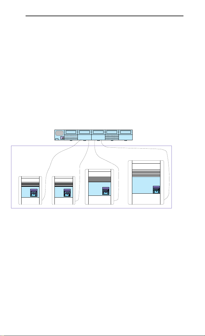
Wiring
To wire the 1203 base used by this module, connect a SCANport
cable from the SCANport device to the desired channel.
SCANport cables are available in either Male–to–Male or
Male–to–Female configurations. You can connect cables of up to
10 meters (33 feet) between a SCANport device and any
SCANport peripheral.
If you use a port expander, you must subtract the cable length between any device
"
and the expander from the maximum cable length used to connect a peripheral.
The following diagram shows a typical network configuration:
Flex Modules
SCANport devices
1–3
1203-5.7-- April 1996
Page 4
1–4
FLEX I/O SCANportt Module Installation Instructions
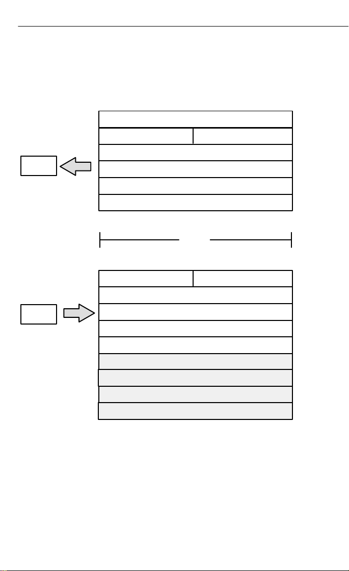
Image Table
The following Flex I/O image table represents the internal data
I/O mapping for the Flex I/O to SCANport module.
Read
6 Words
Write
5 W
ords
I/O Image
Connection Status Channel 2
Logic Status Channel 1
Analog Feedback Channel 1
Logic Status Channel 2
Analog Feedback Channel 2
Connection Enable Channel 2
Logic Command Channel 1
Analog Reference Channel 1
Logic Command Channel 2
Analog Reference Channel 2
Module Image
0
Connection
1 W
ord
Not Used
Not Used
Not Used
Not Used
Status Channel 1
Connection Enable Channel 1
1203-5.7-- April 1996
Page 5

FLEX I/O SCANportt Module Installation Instructions
1–5
Connection
Status W
ord Definition
Connection Status Channel 2 Connection Status Channel 1
Bit:
15 14 13 12 11 10 9 8 7 6 5 4 3 2 1 0
Not Used V2 ID2 Not Used V1 ID1
Description
V1 SCANport channel 1 valid data bit. When high (1), the Logic Status
and Analog Feedback values are valid and can be used. When low
(0), the values should not be used.
ID1 SCANport channel 1 connected peripheral port ID number. This three
bit field contains the port number that channel 1 is connected to on the
SCANport device. It should contain a value between 1 and 7. If this
field is 7, then the channel is not connected to the SCANport device, or
the SCANport device may not be powered.
V2 SCANport channel 2 valid data bit. When high (1), the Logic Status
and Analog Feedback values are valid and can be used. When low
(0), the values should not be used.
ID2 SCANport channel 2 connected peripheral port ID number. This three
bit field contains the port number that channel 2 is connected to on the
SCANport device. It should contain a value between 1 and 7. If this
field is 7, then the channel is not connected to the SCANport device, or
the SCANport device may not be powered.
Logic
Status/Analog Feedback Definition
The Logic Status and Analog Feedback values are defined within
the product manuals of the connected SCANport device(s).
1203-5.7-- April 1996
Page 6
1–6
FLEX I/O SCANportt Module Installation Instructions
Connection
Connection
Bit:
E1 SCANport channel 1 enable bit. When set to 1, the module will
E2 SCANport channel 2 enable bit. When set to 1, the module will
Logic
Enable W
ord Definition
Enable Channel 2Connection Enable Channel 1
15 14 13 12 11 10 9 8 7 6 5 4 3 2 1 0
Not Used E2 Not Used E1
Description
attempt to connect to the SCANport device. When reset to 0, the
module stops communicating with the connected SCANport device.
This usually causes the device to fault.
attempt to connect to the SCANport device. When reset to 0, the
module stops communicating with the connected SCANport device.
This usually causes the device to fault.
Command/Analog Reference Definition
The Logic Command and Analog Reference values are defined
within the product manuals of the connected SCANport device(s).
Indicators
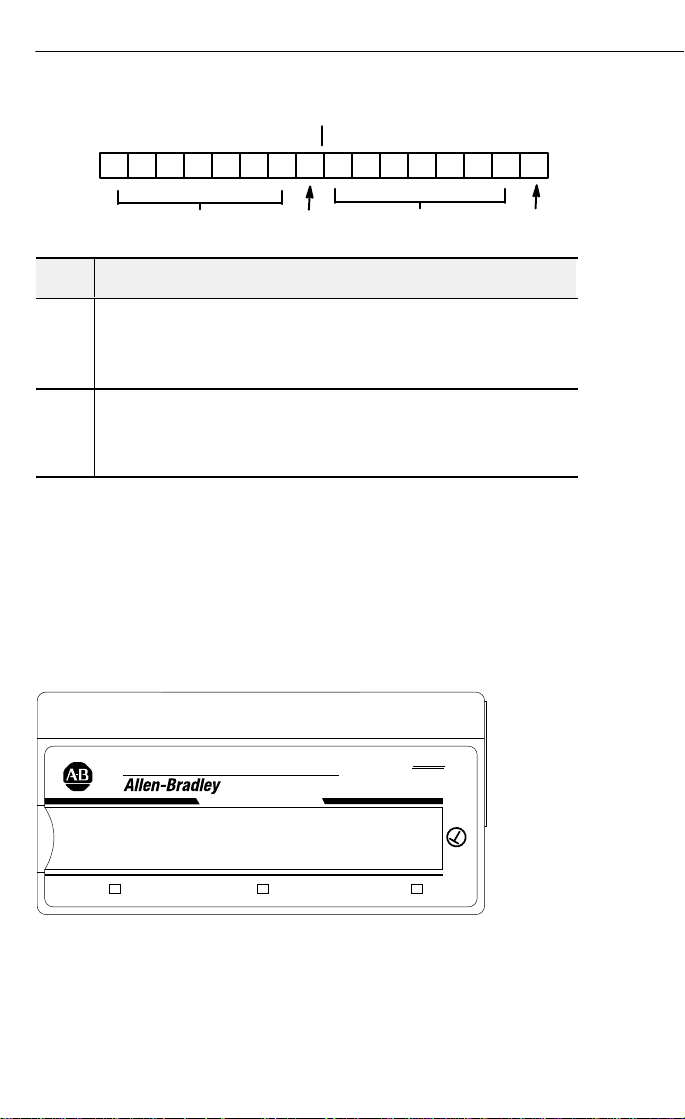
LED
The status LEDs are located on the module’s top label.
CH1 CH2
1203-5.7-- April 1996
SCANPORT
MODULE
Flex I/O
1203-FM1
1
Page 7

FLEX I/O SCANportt Module Installation Instructions
The status LEDs provide the following information:
LED State Description
Module Status
Off Not powered The module is not receiving power.
Green
On-line,
operational
Communications
Red
to the flex adapter
is not operational
Channel 1 or Channel 2 Status
Off
Flashing
green
Solid
green
Flashing
red
No module power The module is not receiving power.
Channel not
enabled
Channel
operational
Channel
communication
problem
Channel
connection or
Solid red
power problem.
Module hardware
problem.
I/O signals are operational between the module
and the flex adapter.
I/O signals are not operational between the
module and the flex adapter.
The enable bit for the channel has not been set.
I/O signals are operational between the module
and the SCANport device.
The module cannot maintain or establish
communications with the SCANport device. You
need to:
•Check the configuration.
•Remove the SCANport cable.
•Re-insert the SCANport cable into the channel
to reset the condition.
The SCANport connection is not operational or the
SCANport device is not powered.
1–7
1203-5.7-- April 1996
Page 8

1–8
Environmental conditions
Temperature
(
)
Operating
0 to
+55°C
(32 to
131°F)
)
Non-operating
40 to
+85°C
185°F)
Humidity
g
Operating
5 to 80% non-condensing
g
Non-operating
5 to 95% non-condensing
Shock
(±1)
Operating
30g peak acceleration
11(±1)ms
pulse width
(±1)
Non-operating
50g peak acceleration
11(±1)ms
pulse width
FLEX I/O SCANportt Module Installation Instructions
Specifications
Category Description
Input voltage rating 5V supplied from Flexbus
Indicators 3 bi-color LEDs
Flexbus current 160mA maximum (refer to Attention on page 2)
Power consumption 0.8W
Keyswitch position 1
Dimensions
Environmental conditions
Temperature
Operating
Non-operating
Humidity
Operating
Non-operating
Shock
Operating
Non-operating
Vibration
Regulatory agencies As specified by product label
45.7H x 94.0W x 53.3D in millimeters
(1.8H x 3.7W x 2.1D in inches)
32 to 131°F
(-40 to
,
,
ms pulse width
ms pulse width
0 to +55°C
-40 to +85°C (-40 to 185°F
-
5 to 80% non-condensin
5 to 95% non-condensin
30g peak acceleration, 11
50g peak acceleration, 11
5g @ 10-500Hz per IEC 68-2-6
1203-5.7-- April 1996
Page 9

FLEX I/O SCANportt Module Installation Instructions
1–9
European
Union Directive Compliance
If this product has the CE mark it is approved for installation
within the European Union and EEA regions. It has been
designed and tested to meet the following directives.
EMC Directive
This product is tested to meet Council Directive 89/336/EEC
Electromagnetic Compatibility (EMC) and the following standards,
in whole or in part, documented in a technical construction file:
• EN 50081-2EMC – Generic Emission Standard, Part 2 – Industrial Environment
• EN 50082-2EMC – Generic Immunity Standard, Part 2 – Industrial Environment
This product is intended for use in an industrial environment.
Low Voltage Directive
This product is tested to meet Council Directive 73/23/EEC
Low Voltage, by applying the safety requirements of EN 61131–2
Programmable Controllers, Part 2 – Equipment Requirements and
Tests.
For specific information required by EN 61131-2, see the appropriate
sections in this publication, as well as the following Allen-Bradley
publications:
• Industrial Automation Wiring and Grounding Guidelines For Noise Immunity, publication
1770-4.1
• Guidelines for Handling Lithium Batteries, publication AG-5.4
• Automation Systems Catalog, publication B111
1203-5.7-- April 1996
Page 10

1–10
FLEX I/O SCANportt Module Installation Instructions
With major offices worldwide.
World
Headquarters,
AllenBradley,
1201 South Second Street,
Milwaukee, WI 53204 USA,
T
el: (1) 414 3822000 Fax: (1) 414 3824444
Publication 12035.8 - April 1996
1203-5.7-- April 1996
Copyright
1996 AllenBradley Company
PN95654201
, Inc. Printed in USA
Page 11

FLEX I/O SCANportt Module Installation Instructions1–46
With majo
World Headquarters,
AllenBradley,
1201 South Second Street,
Milwaukee, WI 53204 USA,
Tel: (1) 414 3822000 Fax: (1) 414 3824444
Publication 12035.8ML - April 1996 PN95654201
r o
ffices worldwide.
Copyright 1996 AllenBradley Company, Inc. Printed in USA
 Loading...