

Page 1

1203-EN1
EtherNet/IP-toSCANport Module
FRN 1.xxx
User Manual
Page 2

Important User Information
Solid state equipment has operational characteristics differing from those of
electromechanical equipment. “Safety Guidelines for the Application, Installation
and Maintenance of Solid State Controls” (Publication SGI-1.1 available from
your local Rockwell Automation Sales Office or online at http://www.ab.com/
manuals/gi) describes some important differences between solid state equipment
and hard-wired electromechanical devices. Because of this difference, and also
because of the wide variety of uses for solid state equipment, all persons
responsible for applying this equipment must satisfy themselves that each intended
application of this equipment is acceptable.
In no event will Rockwell Automation, Inc. be responsible or liable for indirect or
consequential damages resulting from the use or application of this equipment.
The examples and diagrams in this manual are included solely for illustrative
purposes. Because of the many variables and requirements associated with any
particular installation, Rockwell Automation, Inc. cannot assume responsibility or
liability for actual use based on the examples and diagrams.
No patent liability is assumed by Rockwell Automation, Inc. with respect to use of
information, circuits, equipment, or software described in this manual.
Reproduction of the contents of this manual, in whole or in part, without written
permission of Rockwell Automation, Inc. is prohibited.
Throughout this manual we use notes to make you aware of safety considerations.
ATTENTION: Identifies information about practices or circumstances
that can lead to personal injury or death, property damage, or economic
!
loss.
Attentions help you:
• identify a hazard
• avoid the hazard
• recognize the consequences
Important: Identifies information that is especially important for successful
application and understanding of the product.
Shock Hazard labels may be located on or inside the drive to alert
people that dangerous voltage may be present.
ControlFLASH, DriveExplorer, DriveExecutive, DriveTools, and SCANport are trademarks of Rockwell Automation, Inc.
Allen-Bradley and ControlLogix are registered trademarks of Rockwell Automation, Inc.
RSLogix is a trademark of Rockwell Software.
Ethernet is a trademark of Digital Equipment Corporation, Intel Corporation, and Xerox Corporation.
Netscape and Netscape Navigator are registered trademarks of Netscape Communications Corporation.
Windows, Windows CE, Windows NT, Microsoft, and Internet Explorer are either registered trademarks or trademarks of
Microsoft Corporation.
Page 3

Summary of Changes
This is the first release of the 1203-EN1 EtherNet/IP-to-SCANport
module FRN 1.xxx.
Page 4

S-ii Summary of Changes
Page 5

Preface About This Manual
Related Documentation . . . . . . . . . . . . . . . . . . . . . . . . . . . . . P-1
Conventions Used in This Manual . . . . . . . . . . . . . . . . . . . . . P-2
Rockwell Automation Support. . . . . . . . . . . . . . . . . . . . . . . . P-2
Chapter 1 Getting Started
Components . . . . . . . . . . . . . . . . . . . . . . . . . . . . . . . . . . . . . . 1-1
Features . . . . . . . . . . . . . . . . . . . . . . . . . . . . . . . . . . . . . . . . . 1-2
Compatible Products . . . . . . . . . . . . . . . . . . . . . . . . . . . . . . . 1-3
Required Equipment . . . . . . . . . . . . . . . . . . . . . . . . . . . . . . . 1-3
Safety Precautions . . . . . . . . . . . . . . . . . . . . . . . . . . . . . . . . . 1-4
Quick Start . . . . . . . . . . . . . . . . . . . . . . . . . . . . . . . . . . . . . . . 1-5
Modes of Operation . . . . . . . . . . . . . . . . . . . . . . . . . . . . . . . . 1-6
Chapter 2 Installing the Module
Preparing for an Installation. . . . . . . . . . . . . . . . . . . . . . . . . . 2-1
Setting the Web Pages Switch . . . . . . . . . . . . . . . . . . . . . . . . 2-1
Mounting the Module. . . . . . . . . . . . . . . . . . . . . . . . . . . . . . . 2-3
Connecting the Module to the Network and Drive . . . . . . . . 2-5
Applying Power . . . . . . . . . . . . . . . . . . . . . . . . . . . . . . . . . . . 2-6
Commissioning the Module . . . . . . . . . . . . . . . . . . . . . . . . . 2-8
Table of Contents
Chapter 3 Configuring the Module
Configuration Tools . . . . . . . . . . . . . . . . . . . . . . . . . . . . . . . . 3-1
Using DriveExplorer Software. . . . . . . . . . . . . . . . . . . . . . . . 3-2
Using BOOTP . . . . . . . . . . . . . . . . . . . . . . . . . . . . . . . . . . . . 3-3
Setting the IP Address, Subnet Mask, and Gateway Address 3-5
Setting the Data Rate . . . . . . . . . . . . . . . . . . . . . . . . . . . . . . . 3-7
Setting the I/O Configuration. . . . . . . . . . . . . . . . . . . . . . . . . 3-7
Setting the Reference Adjustment . . . . . . . . . . . . . . . . . . . . . 3-8
Selecting Master-Slave or Peer-to-Peer . . . . . . . . . . . . . . . . . 3-9
Setting a Fault Action . . . . . . . . . . . . . . . . . . . . . . . . . . . . . 3-13
Setting Web Features Access . . . . . . . . . . . . . . . . . . . . . . . 3-15
Resetting the Module . . . . . . . . . . . . . . . . . . . . . . . . . . . . . 3-16
Viewing the Module Configuration . . . . . . . . . . . . . . . . . . . 3-17
Chapter 4 Configuring the Scanner or Bridge
Example Network . . . . . . . . . . . . . . . . . . . . . . . . . . . . . . . . . 4-1
Adding a Bridge or Scanner to the I/O Configuration. . . . . . 4-2
Adding the Module and Drive to the I/O Configuration . . . . 4-4
Saving the Configuration . . . . . . . . . . . . . . . . . . . . . . . . . . . . 4-7
Page 6

ii Table of Contents
Chapter 5 Using I/O Messaging
About I/O Messaging . . . . . . . . . . . . . . . . . . . . . . . . . . . . . . . 5-1
Understanding the I/O Image . . . . . . . . . . . . . . . . . . . . . . . . . 5-2
Using Logic Command/Status . . . . . . . . . . . . . . . . . . . . . . . . 5-3
Using Reference/Feedback . . . . . . . . . . . . . . . . . . . . . . . . . . 5-4
Using Datalinks . . . . . . . . . . . . . . . . . . . . . . . . . . . . . . . . . . . 5-5
Example Ladder Logic Program . . . . . . . . . . . . . . . . . . . . . . 5-5
Chapter 6 Using Explicit Messaging
About Explicit Messaging . . . . . . . . . . . . . . . . . . . . . . . . . . . 6-1
Formatting Explicit Messages . . . . . . . . . . . . . . . . . . . . . . . . 6-2
Performing Explicit Messages . . . . . . . . . . . . . . . . . . . . . . . . 6-4
About the Example Explicit Messages . . . . . . . . . . . . . . . . . 6-5
Example Get Attribute Single Message . . . . . . . . . . . . . . . . . 6-6
Example Set Attribute Single Message . . . . . . . . . . . . . . . . . 6-8
Example Get Attributes Scattered Message. . . . . . . . . . . . . 6-10
Example Set Attributes Scattered Message . . . . . . . . . . . . . 6-13
Chapter 7 Troubleshooting
Locating the Status Indicators . . . . . . . . . . . . . . . . . . . . . . . . 7-1
PORT Status Indicator . . . . . . . . . . . . . . . . . . . . . . . . . . . . . . 7-2
MOD Status Indicator . . . . . . . . . . . . . . . . . . . . . . . . . . . . . . 7-3
Net A Status Indicator . . . . . . . . . . . . . . . . . . . . . . . . . . . . . . 7-4
Net B Status Indicator . . . . . . . . . . . . . . . . . . . . . . . . . . . . . . 7-5
Viewing and Clearing Events. . . . . . . . . . . . . . . . . . . . . . . . . 7-6
Chapter 8 Viewing the Module’s Web Pages
Accessing the Module’s Web Home Page . . . . . . . . . . . . . . . 8-1
Process Display Pop-up Windows . . . . . . . . . . . . . . . . . . . . . 8-5
TCP/IP Configuration Web Page . . . . . . . . . . . . . . . . . . . . . . 8-6
Configure E-mail Notification Web Page . . . . . . . . . . . . . . . 8-7
SCANport Device Information Pages . . . . . . . . . . . . . . . . . . 8-9
Appendix A Specifications
Communications . . . . . . . . . . . . . . . . . . . . . . . . . . . . . . . . . A-1
Electrical . . . . . . . . . . . . . . . . . . . . . . . . . . . . . . . . . . . . . . . A-1
Mechanical . . . . . . . . . . . . . . . . . . . . . . . . . . . . . . . . . . . . . . A-1
Environmental . . . . . . . . . . . . . . . . . . . . . . . . . . . . . . . . . . . A-2
Regulatory Compliance . . . . . . . . . . . . . . . . . . . . . . . . . . . . A-2
Appendix B Module Parameters
About Parameter Numbers. . . . . . . . . . . . . . . . . . . . . . . . . . . B-1
Parameter List . . . . . . . . . . . . . . . . . . . . . . . . . . . . . . . . . . . . B-1
Page 7

Table of Contents iii
Appendix C EtherNet/IP Objects
Identity Object . . . . . . . . . . . . . . . . . . . . . . . . . . . . . . . . . . . . C-2
Assembly Object . . . . . . . . . . . . . . . . . . . . . . . . . . . . . . . . . . C-4
Register Object. . . . . . . . . . . . . . . . . . . . . . . . . . . . . . . . . . . . C-6
Parameter Object . . . . . . . . . . . . . . . . . . . . . . . . . . . . . . . . . . C-8
Parameter Group Object. . . . . . . . . . . . . . . . . . . . . . . . . . . . C-11
PCCC Object . . . . . . . . . . . . . . . . . . . . . . . . . . . . . . . . . . . . C-13
SCANport Device Object . . . . . . . . . . . . . . . . . . . . . . . . . . C-18
SCANport Parameter Object . . . . . . . . . . . . . . . . . . . . . . . . C-20
SCANport Fault Object . . . . . . . . . . . . . . . . . . . . . . . . . . . . C-23
SCANport Warning Object . . . . . . . . . . . . . . . . . . . . . . . . . C-25
TCP/IP Interface Object. . . . . . . . . . . . . . . . . . . . . . . . . . . . C-27
Ethernet Link Object . . . . . . . . . . . . . . . . . . . . . . . . . . . . . . C-29
Appendix D Logic Command/Status Words
1336 PLUS II, 1336 PLUS, and 1305 Drives . . . . . . . . . . . D-1
Appendix E N-File Addresses
Appendix F Supported Emulated Block Transfer Commands
What is Emulated Block Transfer . . . . . . . . . . . . . . . . . . . . . F-1
Supported Emulated Block Transfer Commands. . . . . . . . . . F-2
Emulated Block Transfer Status Word. . . . . . . . . . . . . . . . . . F-2
Parameter Value Read . . . . . . . . . . . . . . . . . . . . . . . . . . . . . . F-3
Parameter Value Write . . . . . . . . . . . . . . . . . . . . . . . . . . . . . . F-4
Parameter Read Full. . . . . . . . . . . . . . . . . . . . . . . . . . . . . . . . F-6
Product ID Number Read. . . . . . . . . . . . . . . . . . . . . . . . . . . . F-9
Scattered Parameter Value Read . . . . . . . . . . . . . . . . . . . . . F-11
Scattered Parameter Value Write . . . . . . . . . . . . . . . . . . . . . F-13
NVS Functions. . . . . . . . . . . . . . . . . . . . . . . . . . . . . . . . . . . F-16
Fault Command Write . . . . . . . . . . . . . . . . . . . . . . . . . . . . . F-17
Fault Queue Entry Read Full . . . . . . . . . . . . . . . . . . . . . . . . F-18
Fault Queue Size . . . . . . . . . . . . . . . . . . . . . . . . . . . . . . . . . F-20
Trip Fault Queue Number . . . . . . . . . . . . . . . . . . . . . . . . . . F-22
Glossary
Index
Page 8

iv Table of Contents
Page 9

Preface
About This Manual
Topic Page
Related Documentation
Conventions Used in This Manual P-2
Rockwell Automation Support P-2
Related Documentation
For: Refer to: Publication
EtherNet/IP EtherNet/IP Planning and Installation Manual
DriveExplorer™ http://www.ab.com/drives/driveexplorer, and
DriveExecutive™ http://www.ab.com/drives/drivetools, and
1336 Plus II Drive 1336 Plus II User Manual 1336 PLUS-5.3
1336 IMPACT Drive 1336 IMPACT User Manual 1336 IMPACT-5.0
1336 FORCE Drive 1336 FORCE User Manual 1336 FORCE-5.0
1305 Drive 1305 User Manual 1305-5.2
RSLinx™
or RSLinx Lite
RSLogix™ 5 RSLogix 5 Getting Results Guide
RSLogix™ 500 RSLogix 500 Getting Results Guide, and
®
ControlLogix
1756-ENBT or
1756-ENET/B
and
EtherNet/IP Performance and Application Guide
DriveExplorer Online help (installed with the software)
DriveExecutive Online help (installed with the software)
Getting Results with RSLinx Guide, and
RSLinx Online help (installed with the software)
RSLogix 5 Online help (installed with the software)
RSLogix 500 Online help (installed with the software)
ControlLogix Ethernet Bridge Module User Manual
ControlLogix Ethernet Communications Module User
Manual
P-1
ENET-IN001…
ENET-AP001…
—
—
LINX-GR001…
LG5-GR001…
LG500-GR001…
1756-UM050…
1756-UM051…
Documentation can be obtained online at http://www.ab.com/manuals.
Page 10

P-2 About This Manual
Conventions Used in This Manual
The following conventions are used throughout this manual:
• Parameter names are shown in the format Parameter xx - [*]. The xx
represents the parameter number. The * represents the parameter
name. For example Parameter 01 - [SCANport Adapter].
• Menu commands are shown in bold type face and follow the format
Menu > Command. For example, if you read “Select File > Open,”
you should click the File menu and then click the Open command.
• The firmware release is displayed as FRN X.xxx. The “FRN”
signifies Firmware Release Number. The “X” is the major release
number. The “xxx” is the minor update number.
• RSNetWorx for EtherNet/IP (version 4.01), RSLinx (version 2.41),
and RSLogix5000 (version 12) were used for the screen shots in this
manual. Different versions of the software may differ in appearance
and procedures.
• This manual provides information about the 1203-EN1 EtherNet/IP-
to-SCANport module and using it with SCANport drives. The module
can also be used with other products that support SCANport. Refer to
the documentation for your product for specific information about
how it works with the module.
Rockwell Automation Support
Rockwell Automation, Inc. offers support services worldwide, with over
75 sales/support offices, over 500 authorized distributors, and over 250
authorized systems integrators located through the United States alone.
In addition, Rockwell Automation, Inc. representatives are in every
major country in the world.
Local Product Support
Contact your local Rockwell Automation, Inc. representative for:
• Sales and order support
• Product technical training
• Warranty support
• Support service agreements
Page 11

About This Manual P-3
Technical Product Assistance
If you need to contact Rockwell Automation, Inc. for technical
assistance, please review the information in Chapter 7
first. If you still have problems, call your local Rockwell Automation,
Inc. representative.
U.S. Allen-Bradley Drives Technical Support:
E-mail: support@drives.ra.rockwell.com
Tel: (1) 262.512.8176
Fax (1) 262.512.2222
Online: www.ab.com/support/abdrives
UK Customer Support Center:
E-mail: esupport2@ra.rockwell.com
Tel: +44 (0) 870 2411802
Fax: +44 (0) 1908 838804
Germany Customer Service Center:
E-mail: ragermany-csc@ra.rockwell.com
Tel: +49 (0) 2104 960-630
Fax: +49 (0) 2104 960-501
, Troubleshooting,
Page 12

P-4 About This Manual
Notes:
Page 13
Chapter 1
Getting Started
The 1203-EN1 EtherNet/IP-to-SCANport module is a communication
option intended for use with Allen-Bradley drives and other products
that support SCANport.
Topic Page Topic Page
Components
Features 1-2 Quick Start 1-5
Compatible Products 1-3 Modes of Operation 1-6
Required Equipment 1-3
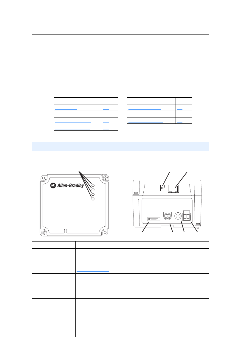
Components
Figure 1.1 Components of the Module
1-1 Safety Precautions 1-4
Front View
1203-EN1
EtherNet/IP to SCANport
10/100 Mbps
➊
PORT
MOD
NET A
NET B
Bottom View
Serial SCANport
➋
N
O
12
DC
+
ADP
➏➐➍
➎
Item Part Description
Status Indicators Four LEDs that indicate the status of the EtherNet/IP connection, SCANpor t,
➊
Web Pages
➋
Switch (SW2)
Ethernet
➌
Connector
24 VDC Power
➍
Terminal Block
AC-to-DC Converter
➎
Connector
SCANport
➏
Connector
and the module itself. Refer to Chapter 7
, Troubleshooting.
Enables and disables the module web pages. Refer to Chapter 2, Setting the
Web Pages Switch. SW1 is unused.
An RJ-45 connector for the Ethernet cable. The connector is CAT-5 compliant
to ensure reliable data transfer on 100Base-TX Ethernet connections.
24 VDC (+15% / -25%) power connection. If the 20-XCOMM-AC-PS1 is used,
this terminal block can be used to daisy-chain 24 VDC to other 1203-EN1’s.
Connection for optional 20-XCOMM-AC-PS1 AC-to-DC converter.
A 20-pin, single-row shrouded male header. An interface cable is
factory-connected to this connector and to a connector on the power supply
board in the 1203-EN1 enclosure base.
RS232 DF1 Port Used to connect software tools using 1203-SFC cable.
➐
➌
+
-
-
DC
Page 14

1-2 Getting Started
Features
The EtherNet/IP-to-SCANport module features the following:
• The module is an external module only. It requires DC power from
either an appropriate DC power source or AC-to-DC converter.
Connectors for both are provided.
• A number of configuration tools can be used to configure the module
and connected drive. These include drive-configuration software tools
such as DriveExplorer (version 4.03 or higher) or DriveExecutive
(version 3.01 or higher). In addition, you can use a BOOTP server to
configure some of the network features on the module (for example,
the IP address).
• Status indicators report the status of the drive, module, and network.
• I/O, including Logic Command/Reference and up to four pairs of
Datalinks, may be configured for your application using parameters.
• Explicit messages (parameter read/write, etc.) are supported.
• Master-Slave and/or Peer-to-Peer hierarchies can be set up so that the
module and connected SCANport drive transmit data to and from a
scanner and/or another SCANport drive on the network.
• User-defined fault actions determine how the module and SCANport
drive respond to communication disruptions on the network.
• Each module has Web pages that display information about the
module and the connected drive.
• The module can be configured to send e-mail messages to desired
addresses when selected drive faults occur and/or are cleared, and/or
when the module takes a communication or idle fault action.
Page 15

Getting Started 1-3
Compatible Products
The EtherNet/IP-to-SCANport module is compatible with Allen-Bradley
drives and other products that support SCANport. SCANport is a
standard peripheral communication interface. At the time of publication,
compatible products include:
• 1305 Drives • 1397 DC Drives
• 1336 PLUS Drives • 1394 Servo Drives
• 1336 PLUS II Drives • 1557 Drives
• 1336 IMPACT Drives • SMC Dialog Plus
• 1336 FORCE Drives • SMP-3 Smart Motor Protectors
• 1336 REGEN Units • 2364F RGU Units
• 1336 SPIDER Drives
Required Equipment
Equipment Shipped with the Module
When you unpack the module, verify that the package includes:
❑ One EtherNet/IP-to-SCANport module in metal enclosure
❑ This manual
User-Supplied Equipment
To install and configure the 1203-EN1 module, you must supply:
❑ A small flathead screwdriver (for wiring the DC power connector)
❑ Bulletin 1202 Communication Cable (1202-Cxx)
❑ Ethernet cable (refer to the EtherNet/IP Media Planning and
Installation Manual, Publication ENET-IN001…, for details.)
❑ Configuration tool, such as:
– DriveExplorer (version 4.03 or higher)
– DriveExecutive (version 3.01 or higher)
– BOOTP Server (version 2.1 or higher) (for network setup only)
❑ Controller configuration software (Example: RSLogix 5000)
❑ A PC connection to the EtherNet/IP network or serial connection via
1203-SFC serial cable
❑ An AC/DC converter such as Allen-Bradley AC Power Adapter
(Catalog # 20-XCOMM-AC-PS1) when DC supply is unavailable.
Page 16

1-4 Getting Started
Safety Precautions
Please read the following safety precautions carefully.
ATTENTION: Risk of injury or equipment damage exists. Only
personnel familiar with drive and power products and the associated
!
machinery should plan or implement the installation, start-up,
configuration, and subsequent maintenance of the product using an
EtherNet/IP module. Failure to comply may result in injury and/or
equipment damage.
ATTENTION: Risk of equipment damage exists. The EtherNet/IP
module contains ESD (Electrostatic Discharge) sensitive parts that can
!
be damaged if you do not follow ESD control procedures. Static control
precautions are required when handling the module. If you are
unfamiliar with static control procedures, refer to Guarding Against
Electrostatic Damage, Publication 8000-4.5.2.
ATTENTION: Risk of injury or equipment damage exists. If the
EtherNet/IP module is transmitting control I/O to the drive, the drive
!
may fault when you reset the module. Determine how your drive will
respond before resetting an module.
ATTENTION: Risk of injury or equipment damage exists.
Parameters 30 - [Comm Flt Action], 31 - [Idle Flt Action], and 51 -
!
[Peer Flt Action] let you determine the action of the module and
connected drive if communications are disrupted or the controller is
idle. By default, these parameters fault the drive. You can set these
parameters so that the drive continues to run. Precautions should be
taken to ensure that the settings of these parameters do not create a risk
of injury or equipment damage. When commissioning the drive, verify
that your system responds correctly to various situations (for example, a
disconnected cable or a faulted controller).
ATTENTION: Risk of injury or equipment damage exists. When a
system is configured for the first time, there may be unintended or
!
incorrect machine motion. Disconnect the motor from the machine or
process during initial system testing.
ATTENTION: Risk of injury or equipment damage exists. The
examples in this publication are intended solely for purposes of
!
example. There are many variables and requirements with any
application. Rockwell Automation, Inc. does not assume responsibility
or liability (to include intellectual property liability) for actual use of
the examples shown in this publication.
Page 17

Getting Started 1-5
Quick Start
This section is provided to help experienced users quickly start using the
EtherNet/IP module. If you are unsure how to complete a step, refer to
the referenced chapter.
Step Refer to . . .
1 Review the safety precautions for the module. Throughout This
2 Verify that the drive is properly installed. Drive User Manual
3 Install the module.
Panel or DIN rail mount the module. Verify that the drive is not
powered. Then, connect the module to the network using an
Ethernet cable and to the drive using a 1202 communications
cable (1202-Cxx).
4 Apply power to the module (and drive).
The module requires DC power, either from a DC power
source or from an AC/DC conver ter. Apply power to the
module. Then apply power to the drive. The status indicators
should be green. If they flash red, there is a problem. Refer to
Chapter 7
, Troubleshooting.
5 Configure the module for your application.
Set the parameters for the following module features as
required by your application:
• IP address, subnet mask, and gateway address
• EtherNet/IP data rate
• I/O configuration
• Master-Slave or Peer-to-Peer hierarchy
• Fault actions
6 Configure the scanner or bridge to communicate with the
module.
Use a software tool such as RSLogix 5000 to configure the
master on the EtherNet/IP network to recognize the module
and drive.
7 Create a ladder logic program.
Use a programming tool such as RSLogix to create a ladder
logic program that enables you to:
• Control the module and connected drive using I/O.
• Monitor or configure the drive using Explicit messages.
Manual
Chapter 2
,
Installing the
Module
,
Chapter 2
Installing the
Module
Chapter 3,
Configuring the
Module
Chapter 4
,
Configuring the
Scanner or Bridge
,
Chapter 5
Using I/O
Messaging
Chapter 6,
Using Explicit
Messaging
Page 18
1-6 Getting Started
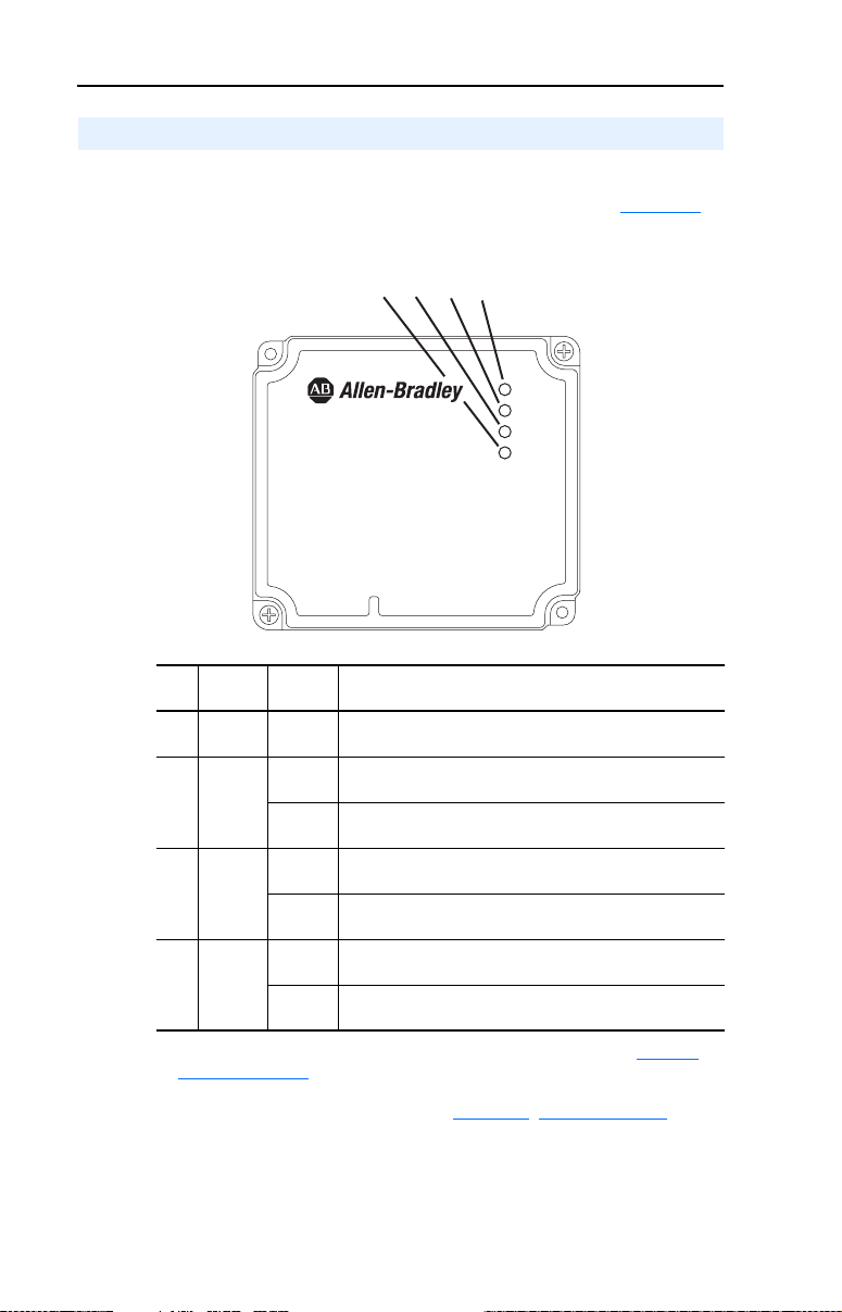
Modes of Operation
The module uses four status indicators to report its operating status.
They can be viewed on the 1203-EN1 enclosure cover. See Figure 1.2
Figure 1.2 Status Indicators
Front View
1203-EN1
EtherNet/IP to SCANport
10/100 Mbps
➍
➌
➋
.
➊
PORT
MOD
NET A
NET B
Item Status
Indicator
PORT Green Normal Operation. The module is properly connected and is
➊
MOD Green Normal Operation. The module is operational and is
➋
NET A Green Normal Operation. The module is properly connected and
➌
NET B Flashing
➍
(1)
If all status indicators are off, the module is not receiving power. Refer to Chapter 2,
Installing the Module
Normal
Status
Flashing
Green
Flashing
Green
Green
Off Normal Operation. The module is not transmitting data
Description
(1)
communicating with the drive.
transferring I/O data.
Normal Operation. The module is operational but is not
transferring I/O data.
communicating on the network.
Normal Operation. The module is properly connected but
does not have an I/O or Explicit Messaging connection.
Normal Operation. The module is properly connected and is
transmitting data packets on the network.
packets.
, for instructions on installing the module.
If any other conditions occur, refer to Chapter 7, Troubleshooting.
Page 19

Chapter 2
Installing the Module
Chapter 2 provides instructions for installing the module.
Topic Page
Preparing for an Installation
Setting the Web Pages Switch 2-1
Mounting the Module 2-3
Connecting the Module to the Network and Drive 2-5
Applying Power 2-6
Commissioning the Module 2-8
Preparing for an Installation
Before installing the EtherNet/IP-to-SCANport module:
• Read the EtherNet/IP Performance and Application Guide,
Publication ENET-AP001…, and EtherNet/IP Media Planning and
Installation Manual, Publication ENET-IN001….
• Verify that you have all required equipment. Refer to Chapter 1
Getting Started
.
2-1
,
Important: To guard against device malfunction, use a grounding wrist
strap when installing the EtherNet/IP module.
Setting the Web Pages Switch
To use the module web pages, the Web Pages Switch must be set to its
“Enable Web” position.
Important: A new setting is recognized only when power is applied to
the module, or the module is reset. If you change a setting,
cycle power or reset the module.
Page 20
2-2 Installing the Module
ATTENTION: Risk of equipment damage exists. The EtherNet/IP
module contains ESD (Electrostatic Discharge) sensitive parts that can
!
be damaged if you do not follow ESD control procedures. Static control
precautions are required when handling the module. If you are
unfamiliar with static control procedures, refer to Guarding Against
Electrostatic Damage, Publication 8000-4.5.2.
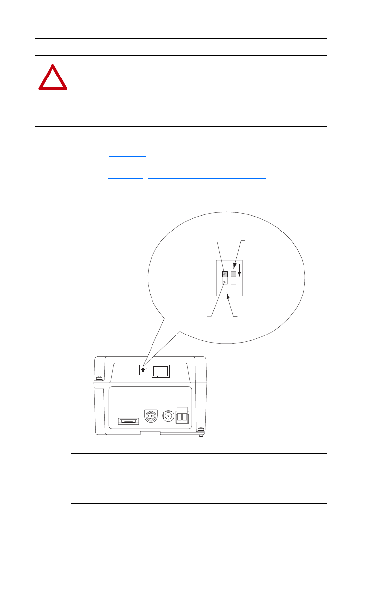
Set the Web Pages Switch (SW2) to enable or disable the module web
pages (see Figure 2.1 and setting descriptions below). By default, the
module web pages are disabled. For complete details on module web
pages, see Chapter 8
Figure 2.1 Setting Web Pages Switch
, Viewing the Module’s Web Pages.
Enable Web
N
O
12
DC
Serial SCANport
ADP
SW2 Setting Description
Up position
Disables the module web pages (default setting).
(UP = OFF)
Down position
Enables the module web pages.
(DN = ON)
Disable Web
Position
Position
+
-
+
-
DC
UNUSED
SWITCH
N
O
12
WEB PAGES
SWITCH
Page 21
Installing the Module 2-3
Mounting the Module
ATTENTION: Risk of equipment damage exists. During panel or
DIN rail mounting, be sure that all debris (metal chips, wire strands,
!
etc.) is kept from falling into the module enclosure. Debris that falls
into the enclosure could cause damage on power up.
Panel or DIN rail mount the module before connecting the module to the
network and drive.
Minimum Spacing
1203-EN1’s can be zero-stacked (side-by-side mounting). Allow 75 mm
(3 in.) of space on the bottom of the module for cable entry. Allow at
least 85 mm (3.2 in.) of enclosure clearance depth to accommodate the
module.
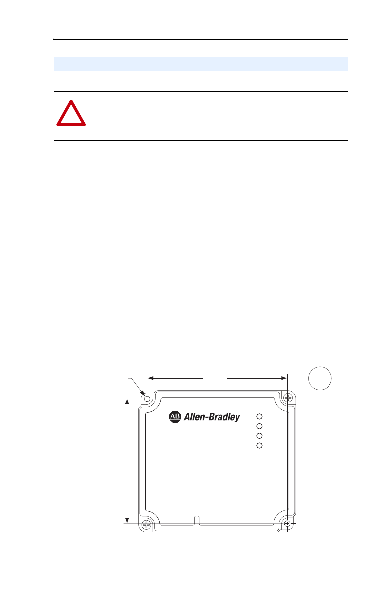
Panel Mounting Using the Dimensional Drawing
Mount the module to a panel using two M4 or #8 panhead screws
(supplied separately).
Figure 2.2 Panel Mounting Dimensions
∅
4
(0.16)
85,3
(3.36)
96,3
(3.79)
1203-EN1
EtherNet/IP to SCANport
10/100 Mbps
PORT
MOD
NET A
NET B
mm
(in.)
Page 22

2-4 Installing the Module
Panel Mounting Procedure Using Module as a Template
The following procedure enables you to use the assembled module as a
template for drilling holes in the panel.
1. Using the assembled module as a template, carefully mark the center
of both holes on the panel.
2. Remove the module to a clean location.
3. Drill and tap the mounting holes for the recommended M4 or #8
panhead screws (supplied separately).
4. Place the module back on the panel, and check for proper hole
alignment.
5. Attach the module to the panel using the mounting screws.
DIN Rail Mounting
The module can be mounted using the following DIN rails:
• 35 x 7.5 mm (EN 50 022 - 35 x 7.5)
• 35 x 15 mm (EN 50 022 - 35 x 15)
Before mounting the module on a DIN rail, open the DIN rail latch.
Press the DIN rail mounting area of the module against the DIN rail, and
manually lock the DIN rail latch (Figure 2.3
Figure 2.3 DIN Rail Mounting
).
Page 23
Installing the Module 2-5
Connecting the Module to the Network and Drive
ATTENTION: Risk of injury or death exists. The drive may contain
high voltages that can cause injury or death. Remove power from the
!
drive, and then verify power has been discharged before installing or
removing an module.
ATTENTION: Risk of equipment damage, injury or death exists.
Unpredictable operation may occur if you fail to verify that parameter
!
settings are compatible with your application. Verify that settings are
compatible with your application before applying power to the drive.
1. Remove power from the drive.
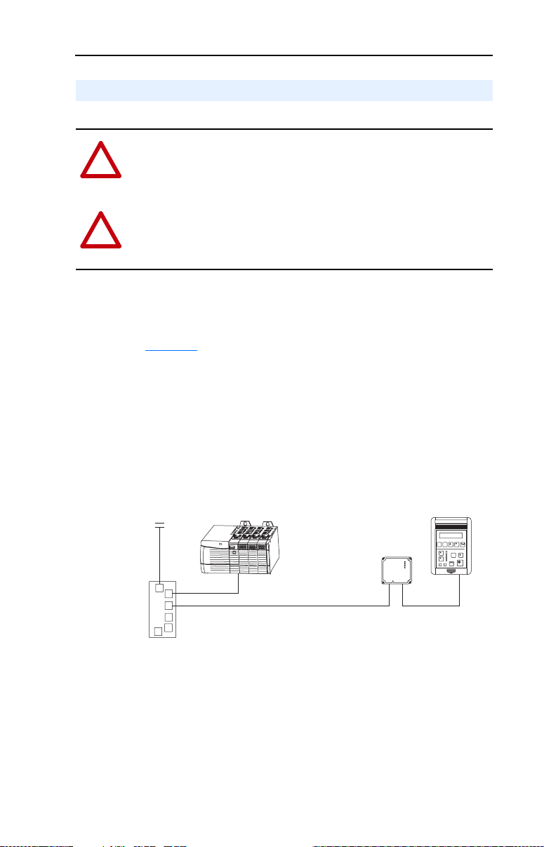
2. Connect an Ethernet cable to the EtherNet/IP network. See
Figure 2.4 for an example of wiring to an EtherNet/IP network.
3. Route the Ethernet cable to the module, and insert the cable’s plug
into the mating module receptacle.
4. Connect a 1202-Cxx Communication Cable to the mating connector
on the module, and then to the port on the drive.
Figure 2.4 Connecting the Ethernet Cable to the Network
Router
(optional)
Switch
ControlLogix with
EtherNet/IP Bridge
EtherNet/IP
Ethernet Cable
1203-EN1
Module
1305 Drive
ESC SEL
JOG
1202-Cxx
Communication
Cable
Page 24

2-6 Installing the Module
Applying Power
ATTENTION: Risk of equipment damage, injury, or death exists.
Unpredictable operation may occur if you fail to verify that parameter
!
settings are compatible with your application. Verify that settings are
compatible with your application before applying power to the drive.
The 1203-EN1 module requires DC power from either an appropriate
DC power source or an AC-to-DC converter. Connectors for both are
provided.
Important: In either case, the DC power source or AC-to-DC converter
that you use must be capable of providing 150 mA @ 18-27
VDC .
Using 24 VDC Power Terminal Block
1. Connect the “+” and “-” wires of your DC power source to the 2-pin
linear plug (provided with the 1203-EN1 module), matching the
respective polarity.
2. Insert the 2-pin linear plug into the mating 24 VDC power terminal
block (Figure 2.1
).
Using AC-to-DC Converter Connector
Plug the AC-to-DC converter such as an Allen-Bradley
20-XCOMM-AC-PS1 AC Power Adapter into the mating DC ADP
receptacle (Figure 2.1
).
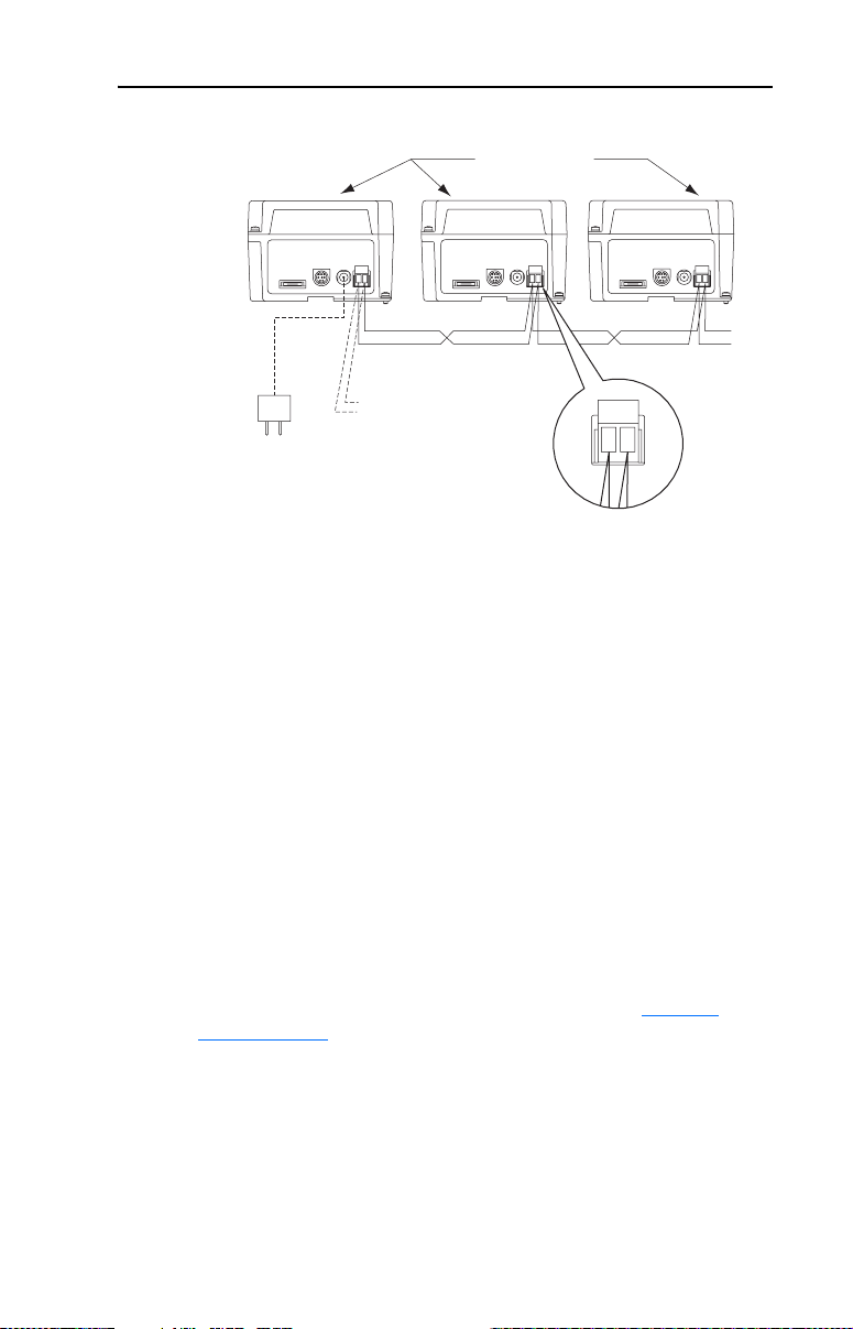
Powering Daisy-Chained 1203-EN1 Modules
You can power additional modules by daisy-chaining them together. For
each module in the chain, connect all DC “+” terminals together and all
DC “-” terminals together (Figure 2.5
twisted wire pairs for better noise immunity.
). We highly recommend using
Page 25
Installing the Module 2-7
Figure 2.5 Powering Multiple Modules via Daisy Chaining
1203-EN1 Modules
+
-
+
-
+
-
. . .
- or -
AC-to-DC
Converter
The number of 1203-EN1’s that can be daisy-chained together is
dependent on the available output capacity of the DC power source or
AC-to-DC converter. The following example illustrates how to
determine the number of daisy-chained 1203-EN1’s that can be powered.
Example: Suppose the 1203-EN1’s being daisy-chained will be powered
by the Allen-Bradley AC-to-DC Converter 20-XCOMM-AC-PS1, which
has an output capacity of 830 mA. Since the current consumed by the
1203-EN1 is 150 mA at 24 VDC, divide the power source’s available
output capacity by this consumption (830 mA ÷ 150 mA = 5.533), and
round down the result. For this example, 5 daisy-chained 1203-EN1’s
can be powered.
LED Status Indication at Power-Up
DC Power
Source
+
-
After making the appropriate power wiring connection(s) to the
module(s), apply power. When power is applied to a module for the first
time, the status indicators should be green or off after an initialization. If
the status indicators go red, there is a problem. Refer to Chapter 7
,
Troubleshooting.
Page 26

2-8 Installing the Module
Commissioning the Module
To commission the module, you must set a unique IP address. (Refer to
the Glossary
and applying power, you can set the IP address by using a BOOTP server
or by setting module parameters.
By default, the module is configured so that you must set the IP address
using a BOOTP server. To set the IP address using module parameters,
you must disable the BOOTP feature. Refer to Chapter 3
the Module, for details.
Important: New settings for some parameters (for example,
for details about IP addresses.) After installing the module
Parameters 03 - [IP Addr Cfg 1] through 06 - [IP Addr
Cfg 4]) are recognized only when power is applied to the
module or the module is reset. After you change parameter
settings, cycle power or reset the module.
, Configuring
Page 27

Chapter 3
Configuring the Module
Chapter 3 provides instructions and information for setting the
parameters in the module.
Topic Page
Configuration Tools
Using DriveExplorer Software 3-2
Using BOOTP 3-3
Setting the IP Address, Subnet Mask, and Gateway Address 3-5
Setting the Data Rate 3-7
Setting the I/O Configuration 3-7
Setting the Reference Adjustment 3-8
Selecting Master-Slave or Peer-to-Peer 3-9
Setting a Fault Action 3-13
Setting Web Features Access 3-15
Resetting the Module 3-16
Viewing the Module Configuration 3-17
For a list of parameters, refer to Appendix B, Module Parameters. For
definitions of terms in this chapter, refer to the Glossary
3-1
.
Configuration Tools
The EtherNet/IP-to-SCANport module stores parameters and other
information in its own non-volatile memory. You must, therefore, access
the module to view and edit its parameters. The following tools can be
used to access the module parameters:
Tool Page
DriveExplorer Software (version 4.03 or higher) 3-2
BOOTP Server (for setting IP address, subnet
mask, and gateway address only)
3-3
Page 28
3-2 Configuring the Module
Using DriveExplorer Software
DriveExplorer can be used with the 1203-EN1 via two connection
methods: RS-232 Serial and EtherNet/IP.
RS-232 Serial (DriveExplorer Lite and Full versions)
A 1203-SFC cable (comes with 1203-SSS AnaCANda and available
separately) is used to connect a PC to the DF1 serial port on the
1203-EN1. The user can adjust parameters on the 1203-EN1 and the
connected Host drive. The Full version of DriveExplorer can also route
out over EtherNet/IP and access other Allen-Bradley drives on the
network. Refer to DriveExplorer documentation for details on
establishing a serial connection.
EtherNet/IP (DriveExplorer Full Version)
Most PC's today come with a built-in Ethernet port. EtherNet/IP
connectivity allows high speed communications (10/100 Mbps) and
faster updates versus an RS-232 serial connection. Refer to
DriveExplorer documentation for details on establishing an EtherNet/IP
connection.
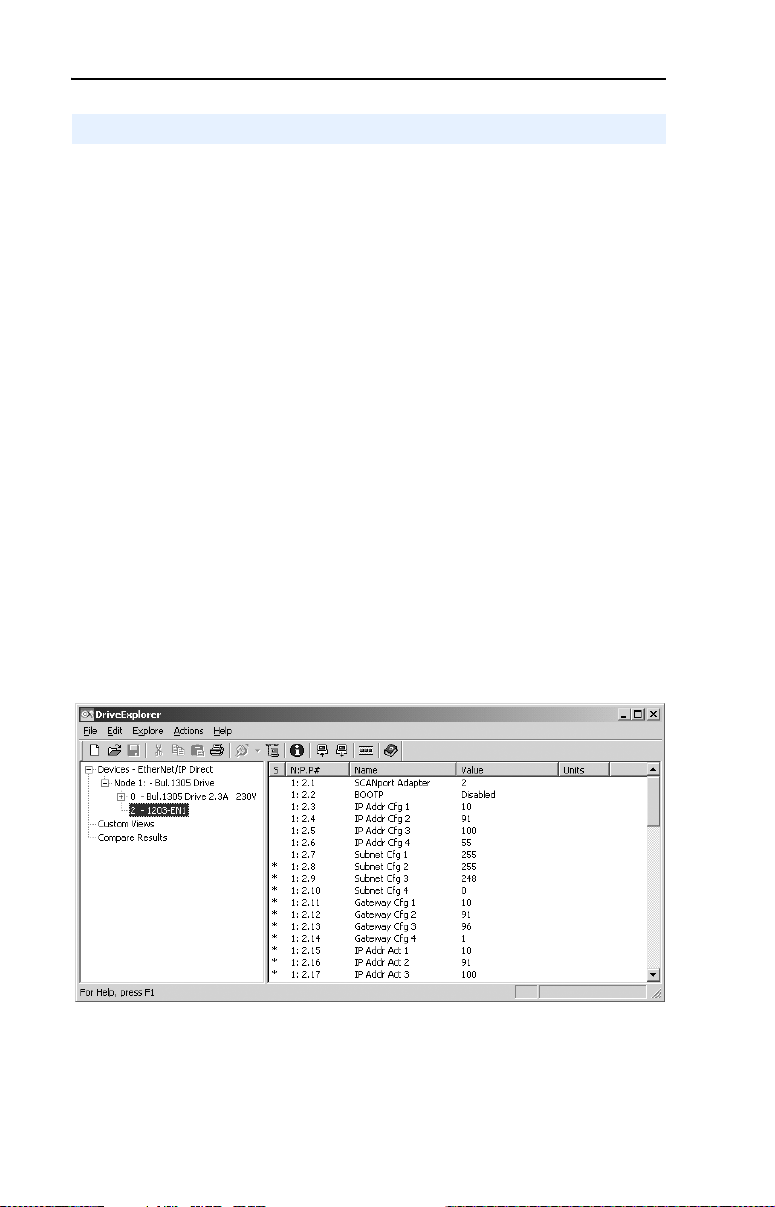
Figure 3.1 Launched DriveExplorer Window for Configuring 1203-EN1 Module
After launching DriveExplorer, access the appropriate configuration
screens to set module parameters. Refer to the respective sections in this
chapter for setup details.
Page 29
Configuring the Module 3-3
Using BOOTP
By default, the module is configured so that you can set its IP address,
subnet mask, and gateway address by using a BOOTP utility. You can
select from a variety of BOOTP utilities. These instructions use
Rockwell’s BOOTP Server (version 2.1), a stand-alone program that
incorporates the functionality of standard BOOTP utilities with a
graphical interface. It is available from http://www.ab.com/networks.
Refer to the Readme file and online Help for detailed directions and
information.
TIP: If desired, you can disable BOOTP and configure the IP address,
subnet mask, and gateway address by setting parameters. For details,
refer to Setting the IP Address, Subnet Mask, and Gateway Address
this chapter.
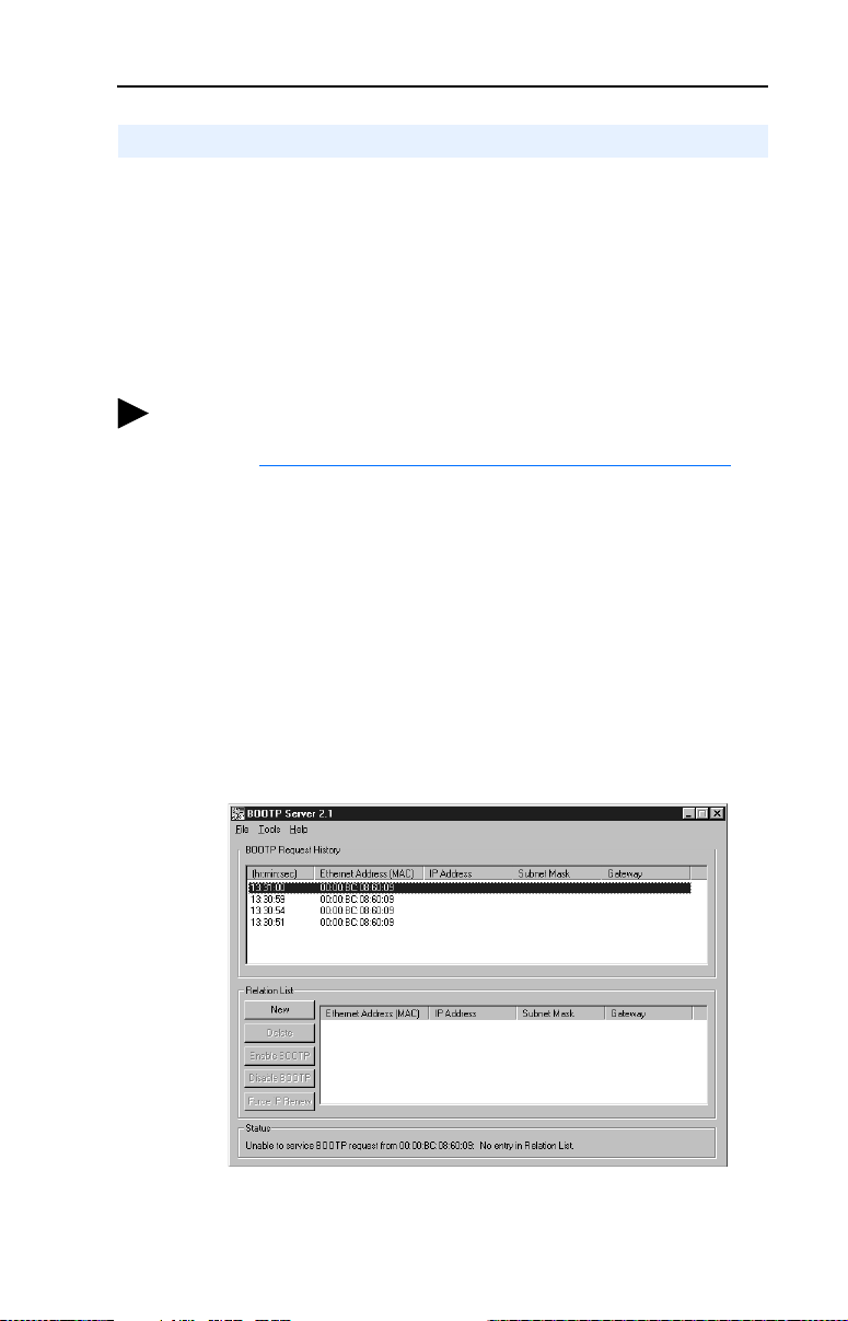
To configure the module IP address, subnet mask, and gateway address using BOOTP Server
1. On the module label, locate and note the module’s hardware address.
2. On a computer connected to the EtherNet/IP network, start the
BOOTP software. The BOOTP Server window appears. Devices on
the network issuing BOOTP requests appear in the BOOTP Request
History list.
in
Figure 3.2 BOOTP Server Window
3. In the BOOTP Request History list, double-click the hardware
address (Ethernet MAC address) of the module.
Page 30
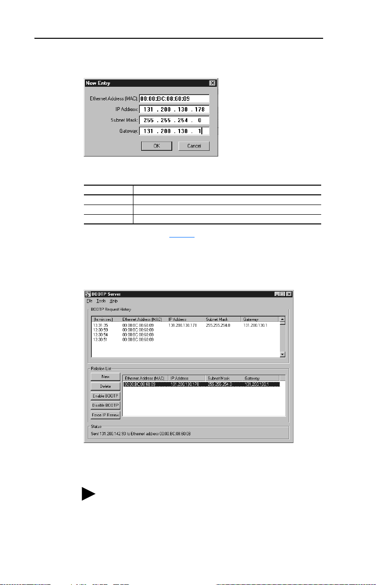
3-4 Configuring the Module
The New Entry dialog box appears.
Figure 3.3 New Entry Dialog Box
4. Enter in the following data:
(1)
Box
IP Address A unique IP address for the module
Subnet Mask The subnet mask for the module’s network
Gateway The IP address of the gateway device on the module’s network
(1)
For definitions, refer to the Glossary.
Type
5. Click OK to apply the settings. The module appears in the Relation
List with the new settings.
Figure 3.4 BOOTP Server Window with a Module in the Relation List
6. To assign this configuration to the module permanently, click
Disable BOOTP. When power is cycled on the module, it will use
the configuration you assigned it and not issue new BOOTP requests.
TIP: To enable BOOTP for an module that has had BOOTP
disabled, first select the module in the Relation List (add if
necessary), then click Enable BOOTP, and finally reset the
module.
7. To save the Relation List, select File > Save.
Page 31

Configuring the Module 3-5
Setting the IP Address, Subnet Mask, and Gateway Address
By default, the module is configured so that you set its IP address, subnet
mask, and gateway address using a BOOTP server. If you want to set
these features using the module’s parameters instead, you must disable
BOOTP and then set the appropriate parameters in the module using a
serial connection.
DriveExplorer (version 4.03) was used for set up examples in this
chapter. Different versions of software may differ in appearance and
procedures.
To disable the BOOTP feature
1. Set the value of Parameter 02 - [BOOTP] to Disabled.
Table 3.A Parameter 02 - [BOOTP] Setup Values
Value Setting
0Disabled
1 Enabled (Default)
2. Reset the module. See Resetting the Module
section in this chapter.
After disabling the BOOTP feature, you can then configure the IP
address, subnet mask, and gateway using the module’s parameters.
To set an IP address using parameters
1. Verify that Parameter 02 - [BOOTP] is set to Disabled. This
parameter must be set to Disabled to configure the IP address using
parameters.
2. Set the value of Parameters 03 - [IP Addr Cfg 1] through 06 - [IP
Addr Cfg 4] to a unique IP address.
Figure 3.5 Example IP Address Parameter Setup Values
Default = 0.0.0.0
[IP Addr Cfg 1]
255 . 255 . 255 . 255
[IP Addr Cfg 2]
[IP Addr Cfg 3]
[IP Addr Cfg 4]
Page 32

3-6 Configuring the Module
3. Reset the module. See Resetting the Module section in this chapter.
The Net A status indicator will be solid green or flashing green if the
IP address is correctly configured.
To set a subnet mask using parameters
1. Verify that Parameter 02 - [BOOTP] is set to Disabled. This
parameter must be set to Disabled to configure the subnet mask using
parameters.
2. Set the value of Parameters 07 - [Subnet Cfg 1] through 10 [Subnet Cfg 4] to the desired value for the subnet mask.
Figure 3.6 Example Subnet Mask Parameter Setup Values
Default = 0.0.0.0
[Subnet Cfg 1]
255 . 255 . 255 . 255
[Subnet Cfg 2]
[Subnet Cfg 3]
[Subnet Cfg 4]
3. Reset the module. See Resetting the Module section in this chapter.
To set a gateway address for the module using parameters
1. Verify that Parameter 02 - [BOOTP] is set to Disabled. This
parameter must be set to Disabled to configure the gateway address
using parameters.
2. Set the value of Parameters 11 - [Gateway Cfg 1] through 14 [Gateway Cfg 4] to the IP address of the gateway device.
Figure 3.7 Example Gateway Parameter Setup Values
Default = 0.0.0.0
[Gateway Cfg 1]
255 . 255 . 255 . 255
[Gateway Cfg 2]
[Gateway Cfg 3]
[Gateway Cfg 4]
3. Reset the module. See Resetting the Module section in this chapter.
Page 33

Configuring the Module 3-7
Setting the Data Rate
By default, the module is set to autodetect, so it automatically detects the
data rate and duplex setting used on the network. If you need to set a
specific data rate and duplex setting, the value of Parameter 27 - [EN
Rate Cfg] determines the Ethernet data rate and duplex setting that the
module will use to communicate. For definitions of data rate and duplex,
refer to the Glossary
1. Set the value of Parameter 27 - [EN Rate Cfg] to the data rate at
which your network is operating.
Table 3.B Parameter 27 - [EN Rate Cfg] Data Rate Setup Values
Value Data Rate
0 Autodetect (default)
1 10 Mbps Full
2 10 Mbps Half
3 100 Mbps Full
4 100 Mbps Half
2. Reset the module. See Resetting the Module section in this chapter.
.
Setting the I/O Configuration
The I/O configuration determines the data that is sent to and from the
drive. Logic Command/Status, Reference/Feedback, and Datalinks may
be enabled or disabled. A “1” enables the I/O. A “0” disables the I/O.
1. Set the bits in Parameter 32 - [SP I/O Cfg].
Table 3.C Parameter 32 - [SP I/O Cfg] Bit Assignments
Bit Description
0 Logic Command/Reference (Default)
1 Datalink A
2 Datalink B
3 Datalink C
4 Datalink D
5 - 7 Not Used
Bit 0 is the right-most bit.
2. If Logic Command/Reference is enabled, configure the parameters in
the drive to accept the Logic Command and Reference from the
module. For example, set Parameter 5 - [Freq Select 1] in a 1305
Page 34

3-8 Configuring the Module
drive to “Adapter 2” so that the drive uses the Reference from the
module. Also, verify that the mask parameters (for example,
Parameter 92 - [Logic Mask]) in the drive are configured to receive
the desired logic from the module. Refer to the documentation for
your drive for details.
3. If you enabled one or more Datalinks, configure parameters in the
drive to determine the source and destination of data in the
Datalink(s). For example, configure the datalinks in 1305 drives by
setting Parameters 111 - [Data In A1] to 126 - [Data Out D2].
Also, ensure that the EtherNet/IP module is the only module using
the enabled Datalink(s).
4. Reset the module. See Resetting the Module
The module is ready to receive I/O. You must now configure the module
to receive I/O from a master or peer device. Refer to Selecting
Master-Slave or Peer-to-Peer in this chapter. If you select a Master-Slave
hierarchy, you must also configure the master to communicate with the
module. Refer to Chapter 4
, Configuring the Scanner or Bridge.
section in this chapter.
Setting the Reference Adjustment
A Reference Adjustment is a percent scaling factor for the Reference
from the network and can be set from 0 to 200%. This allows the drive’s
Reference to either match the network Reference (=100%), scale below
the network Reference (<100%), or scale above the network Reference
(>100%).
ATTENTION: To guard against equipment damage and/or
personal injury, note that changes to Parameter 47 - [Ref
!
Adjust] take effect immediately. A drive receiving its
Reference from the module will receive the newly scaled
Reference, resulting in a change of speed.
If the module is receiving a Reference, adjust the scale using Parameter
47 - [Ref Adjust]. It can be scaled between 0.00 and 200.00%. The
default is 100.00%.
The adjustment takes effect as soon as it is entered.
Page 35

Configuring the Module 3-9
Selecting Master-Slave or Peer-to-Peer
A hierarchy determines the type of device with which the module
exchanges data. In a Master-Slave hierarchy, a module exchanges data
with a master, such as a scanner or bridge. In a Peer-to-Peer hierarchy, a
module exchanges data with one or more EtherNet/IP modules connected
to devices that have compatible Logic Command/Status words.
For both master-slave and peer-to-peer hierarchies, the devices
exchanging data must be on the same IP subnet. See “IP Addresses” in
the Glossary
To set a Master-Slave hierarchy
1. Enable the desired I/O in Parameter 32 - [SP I/O Cfg]. Refer to
Setting the I/O Configuration
2. Set the bits in Parameter 45 - [M-S Input]. This parameter
determines the data received from the master by the drive. A “1”
enables the I/O. A “0” disables the I/O.
Table 3.D Parameter 45 - [M-S Input] Bit Assignments
for information about IP subnets.
in this chapter.
Bit Description
0 Logic Command/Reference (Default)
1 Datalink A Input
2 Datalink B Input
3 Datalink C Input
4 Datalink D Input
5 - 7 Not Used
Bit 0 is the right-most bit.
3. Set the bits in Parameter 46 - [M-S Output]. This parameter
determines the data transmitted from the drive to the scanner. A “1”
enables the I/O. A “0” disables the I/O.
Table 3.E Parameter 46 - [M-S Output] Bit Assignments
Bit Description
0 Status/Feedback (Default)
1 Datalink A Output
2 Datalink B Output
3 Datalink C Output
4 Datalink D Output
5 - 7 Not Used
Bit 0 is the right-most bit.
Page 36

3-10 Configuring the Module
4. Reset the module. See Resetting the Module section in this chapter.
The module is ready to receive I/O from the master (i.e., scanner). You
must now configure the scanner to recognize and transmit I/O to the
module. Refer to Chapter 4
To set a module to transmit Peer-to-Peer data
1. Verify that Parameter 61 - [Peer Out Enable] is set to Off. This
parameter must be Off while you configure peer output parameters.
Table 3.F Parameter 61 - [Peer Out Enable] Setup Values
Value Setting
0 Off (Default)
1On
2. Select the source of the data to output to the network in Parameter
59 - [Peer A Output].
Table 3.G Parameter 59 - [Peer A Output] Setup Values
Value Description
0 Off (Default)
1 Logic Command/Reference
2 - 5 Datalink A, B, C, or D Input
6 - 9 Datalink A, B, C, or D Output
, Configuring the Scanner or Bridge.
3. If desired, select an additional source of the data to output to the
network in Parameter 60 - [Peer B Output].
Table 3.H Parameter 60 - [Peer B Output] Setup Values
Value Description
0 Off (Default)
1 Logic Command/Reference
2 - 5 Datalink A, B, C, or D Input
6 - 9 Datalink A, B, C, or D Output
4. Set Parameters 62 - [Peer Out Time] and 63 - [Peer Out Skip] to
establish the minimum and maximum intervals between Peer
messages. Because the module transmits Peer messages when a
change-of-state condition occurs, minimum and maximum intervals
are required.
– The minimum interval ensures that the module does not transmit
messages on the network too often, thus minimizing network
traffic. It is set in Parameter 62 - [Peer Out Time]. The default
is 10.00 seconds.
Page 37

Configuring the Module 3-11
– The maximum interval ensures that the module transmits
messages often enough so that the receiving module(s) can
receive recent data and verify that communications are working
or, if communications are not working, can timeout. The
maximum interval is the value of Parameter 62 - [Peer Out
Time] multiplied by the value of Parameter 63 - [Peer Out
Skip], which has a default of 1.
For example, suppose the minimum interval (Parameter 62 - [Peer
Out Time]) is set to 2.00 seconds, and the desired maximum interval
is 4.00 seconds. Then, the Parameter 63 - [Peer Out Skip] value
would be “2” (2.00 x 2 = 4.00).
5. Set Parameter 61 - [Peer Out Enable] to On (value = 1). The
module will transmit the data selected in Parameters 59 - [Peer A
Output] and 60 - [Peer B Output] to the network. Another module
must be configured to receive the Peer I/O data.
To set a module to receive Peer-to-Peer data
1. Verify that Parameter 57 - [Peer Inp Enable] is set to Off. This
parameter must be set to Off while you configure the peer input
parameters.
Table 3.I Parameter 57 - [Peer Inp Enable] Setup Values
Value Setting
0 Off (Default)
1On
2. In Parameters 52 - [Peer Inp Addr 1] through 55 - [Peer Inp Addr
4], set the IP address of the node from which you want to receive
data. Valid nodes must have 1203-EN1 modules connected to drives
with compatible Logic Command/Status words.
Figure 3.8 Example Peer Input Address 1 Parameter Setup Values
IP Address of Node
Transmitting Peer I/O
[Peer Inp Addr 1]
Default = 0.0.0.0
255 . 255 . 255 . 255
[Peer Inp Addr 2]
[Peer Inp Addr 3]
[Peer Inp Addr 4]
Page 38

3-12 Configuring the Module
3. Select the destination of the data that is input to the drive as Peer A in
Parameter 48 - [Peer A Input].
Table 3.J Parameter 48 - [Peer A Input] Setup Values
Value Description
0 Off (Default)
1 Logic Command/Reference
2 - 5 Datalink A, B, C, or D Input
4. If desired, select the destination of the data to input to the drive as
Peer B in Parameter 49 - [Peer B Input].
Table 3.K Parameter 49 - [Peer B Input] Setup Values
Value Description
0 Off (Default)
1 Logic Command/Reference
2 - 5 Datalink A, B, C, or D Input
5. If the module receives a Logic Command, set the bits in Parameter
50 - [Peer Cmd Mask] that the drive should use. The bit definitions
for the Logic Command word will depend on the drive to which the
module is connected. Refer to Appendix D
ATTENTION: If the module receives a Logic Command from both a
Master device and a Peer device, each command bit must have only one
!
source. This includes the stop bit. The source of command bits set to
“0” will be the Master device. The source of command bits set to “1”
will be the Peer device.
or drive documentation.
Table 3.L Parameter 50 - [Peer Cmd Mask] Setup Values
Value Description
0 Ignore this command bit. (Default)
1 Use this command bit.
6. Set Parameter 56 - [Peer Inp Timeout] to the maximum amount of
time the module will wait for a message before timing out. The
default is 10.00 seconds.
Important: This value must be greater than the product of
Parameter 62 - [Peer Out Time] multiplied by
Parameter 63 - [Peer Out Skip] in the module from
which you are receiving I/O.
For example, if the value of Parameter 62 - [Peer Out Time] is 2.00
and the value of Parameter 63 - [Peer Out Skip] is 2 (2.00 x 2 =
Page 39

Configuring the Module 3-13
4.00), then Parameter 56 - [Peer Inp Timeout] needs to have a
value greater than 4.00, such as 5.00.
7. Set the action in Parameter 51 - [Peer Flt Action] that the module
will take if it times out.
ATTENTION: Risk of injury or equipment damage exists.
Parameter 51 - [Peer Flt Action] lets you determine the action of the
!
module and connected drive if communications are disrupted. By
default, this parameter faults the drive. You can set this parameter so
that the drive continues to run. Precautions should be taken to ensure
that the setting of this parameter does not create a hazard of injury or
equipment damage. When commissioning the drive, verify that your
system responds correctly to various situations (for example, a
disconnected cable).
Table 3.M Parameter 51 - [Peer Flt Action] Setup Values
Value Description
0 Fault (Default)
1 Zero Data
2 Hold Last
3 Send Flt Cfg
For details, see Setting a Fault Action
8. Set Parameter 57 - [Peer Inp Enable] to On (value = 1).
9. Reset the module. See Resetting the Module
The module is now configured to receive Peer I/O from the specified
node. Ensure that the specified node is configured to transmit Peer I/O.
Parameter 58 - [Peer Inp Status] will display “Running” if Peer I/O is
working.
section in this chapter.
section in this chapter.
Setting a Fault Action
By default, when communications are disrupted (for example, a cable is
disconnected) or the scanner is idle (for example, in program mode or its
controller is faulted), the drive responds by faulting if it is using I/O from
the network. You can configure a different response to communication
disruptions using Parameter 30 - [Comm Flt Action] and a different
response to an idle scanner using Parameter 31 - [Idle Flt Action].
Page 40

3-14 Configuring the Module
ATTENTION: Risk of injury or equipment damage exists.
Parameters 30 - [Comm Flt Action] and 31 - [Idle Flt Action] let you
!
determine the action of the module and connected drive if
communications are disrupted or the scanner is idle. By default, these
parameters fault the drive. You can set these parameters so that the
drive continues to run. Precautions should be taken to ensure that the
settings of these parameters do not create a risk of injury or equipment
damage. When commissioning the drive, verify that your system
responds correctly to various situations (for example, a disconnected
cable or faulted controller).
To change the fault action
Set the values of Parameters 30 - [Comm Flt Action] and 31 -[Idle Flt
Action] to the desired responses:
Table 3.N Parameters 30 - [Comm Flt Action] and 31 - [Idle Flt Action] Setup Values
Value Action Description
0 Fault The drive is faulted and stopped. (Default)
1 Zero Data The drive is sent 0 for output data after a communications
2 Hold Last The drive continues in its present state after a
3 Send Flt Cfg The drive is sent the data that you set in the fault
disruption. This does not command a stop.
communications disruption.
configuration parameters (Parameters 34 - [Flt Cfg Logic]
through 43 - [Flt Cfg D2 In]).
Changes to these parameters take effect immediately. A reset is not required.
To set the fault configuration parameters
If you set Parameter 30 - [Comm Flt Action] or 31 - [Idle Flt Action]
to “Send Flt Cfg,” the values in the following parameters are sent to the
drive after a communications fault and/or idle fault occurs. You must set
these parameters to values required by your application.
Parameter Name Description
34 Flt Cfg Logic A 16-bit value sent to the drive for Logic Command.
35 Flt Cfg Ref A 16-bit value (0 – 65535) sent to the drive as a
36 – 43 Flt Cfg x1 In
or
Flt Cfg x2 In
Changes to these parameters take effect immediately. A reset is not required.
Reference or Datalink.
Page 41

Configuring the Module 3-15
Setting Web Features Access
By accessing the IP address set for the module using a web browser, you
can view the module’s web pages for information about the module and
the drive to which it is connected. Additionally, the module can be
configured to automatically send e-mail messages to desired addresses
when selected drive faults occur and/or are cleared, and/or when the
module takes a communication or idle fault action. For more details on
the module’s web pages, refer to Chapter 8
Pages.
By default, the module web pages are disabled.
To enable the module web pages
• Refer to Figure 2.1 and set the Web Pages Switch (SW2) to the
“Enable Web” (down) position.
Important: For a change to the switch setting to take effect, the
module must be reset (see Resetting the Module
in this chapter).
Bit 0 of Parameter 65 - [Web Features] is used to protect the
configured settings for e-mail notification. By default, settings are not
protected. To protect an e-mail configuration, set the value of E-mail Cfg
Bit 0 to “0” (Disabled). You can unprotect the configuration by changing
Bit 0 back to “1” (Enabled). E-mail notification will always remain
active regardless of whether or not its settings are protected — unless
e-mail notification was never configured. For more information about
configuring module e-mail notification or stopping e-mail messages,
refer to Chapter 8
Table 3.O Parameter 65 - [Web Features] Bit Assignments
, Configure E-mail Notification Web Page).
, Viewing the Module’s Web
section
Bit Description
0 (right-most bit) E-mail Cfg (Default = 1 = Enabled)
1 - 7 Not Used
Changes to this parameter take effect immediately. A reset is not required.
Page 42

3-16 Configuring the Module
Resetting the Module
Changes to switch settings and some module parameters require that you
reset the module before the new settings take effect. You can reset the
module by cycling power to the module or by using the following
parameter:
ATTENTION: Risk of injury or equipment damage exists. If the
module is transmitting control I/O to the drive, the drive may fault when
!
you reset the module. Determine how your drive will respond before
resetting a connected module.
Set Parameter 29 - [Reset Module] to Reset Module.
Table 3.P Parameter 29 - [Reset Module] Setup Values
Value Description
0 Ready (Default)
1 Reset Module
2 Set Defaults
When you enter 1 = Reset Module, the module will be immediately
reset. When you enter 2 = Set Defaults, the module will set all module
parameters to their factory-default settings. After performing a Set
Defaults, enter 1 = Reset Module so that the new values take effect. The
value of this parameter will be restored to 0 = Ready after the module is
reset.
Page 43

Configuring the Module 3-17
Viewing the Module Configuration
The following parameters provide information about how the module is
configured. You can view these parameters at any time using
DriveExplorer (version 4.03 or higher) or DriveExecutive (version 3.01
or higher) software.
Param Number Name Description
28 EN Rate Act The data rate used by the module.
15 – 18 IP Addr Act 1 – 4 The actual IP address used by the module.
19 – 22 Subnet Act 1 – 4 The actual subnet mask used by the module.
23 – 26 Gateway Act 1 – 4 The actual gateway address used by the module.
33 SP I/O Act The Reference/Feedback and Datalinks used by
58 Peer Inp Status The status of the consumed peer input connection:
the module. This value is the same as Parameter
32 - [SP I/O Cfg] unless the parameter was
changed and the module was not reset.
Val ues
0 = Off
1 = Waiting
2 = Running
3 = Faulted
Page 44

3-18 Configuring the Module
Notes:
Page 45

Chapter 4
Configuring the Scanner or Bridge
Chapter 4 provides instructions on how to configure a ControlLogix
bridge to communicate with the module and connected 1305 drive.
Topic Page
Example Network
Adding a Bridge or Scanner to the I/O Configuration 4-2
Adding the Module and Drive to the I/O Configuration 4-4
Saving the Configuration 4-7
Example Network
After the module is configured, the connected drive and module will be a
single node on the network. This chapter provides the steps that are
needed to configure a simple network like the network in Figure 4.1
our example, we will configure a 1756-ENBT bridge to communicate
with a drive using Logic Command/Status, Reference/Feedback, and
four 16-bit datalinks over the network.
4-1
. In
Figure 4.1 Example EtherNet/IP Network
ControlLogix Controller
with 1756-ENBT Bridge
Switch
1203-EN1
EtherNet/IP
Module
Computer with
Ethernet/IP Connection
1305 Drive
ESC SEL
JOG
Page 46

4-2 Configuring the Scanner or Bridge
Adding a Bridge or Scanner to the I/O Configuration
To establish communications over an EtherNet/IP network, you must
first add the controller and its scanner or bridge to the I/O configuration.
1. Start RSLogix 5000. The RSLogix 5000 window appears.
Figure 4.2 RSLogix 5000 Window
2. In the Control Organizer pane, right-click the I/O Configuration
folder and select New Module (Figure 4.2
dialog box (Figure 4.3) appears.
Figure 4.3 Select Module Type Dialog Box
). The Select Module Type
➌
➌
➍
Page 47

Configuring the Scanner or Bridge 4-3
3. In the list, select the EtherNet/IP scanner or bridge used by your
controller and then select the major revision of its firmware in the
Major Revision box. In this example (Figure 4.3
), we use a
1756-ENBT EtherNet/IP Bridge (Series B), so the 1756-ENBT/B
option is selected.
4. Click OK. The Module Properties dialog box (Figure 4.4
Figure 4.4 Module Properties Dialog Box - Page 1
5. Edit the following:
Box Type
Name A name to identify the scanner or bridge.
Slot The slot of the EtherNet/IP scanner or bridge in the rack.
Revision The minor revision of the firmware in the scanner. (You
IP Address The IP address of the EtherNet/IP scanner or bridge.
Electronic Keying Compatible Module. This setting for Electronic Keying
already set the major revision in the Select Module Type
dialog box, Figure 4.3
ensures the physical module is consistent with the software
configuration before the controller and scanner or bridge
make a connection. Therefore, ensure that you have set the
correct revision in this dialog box. Refer to the online Help if
the controller and scanner have problems making a
connection and you want to change this setting.
.)
) appears.
6. Click Finish>>. The scanner or bridge is now configured for the
EtherNet/IP network. It appears in the I/O Configuration folder. In
our example, a 1756-ENBT bridge appears under the I/O
Configuration folder (Figure 4.5
Figure 4.5 RSLogix 5000: I/O Configuration Folder
).
Page 48

4-4 Configuring the Scanner or Bridge
Adding the Module and Drive to the I/O Configuration
To transmit data between the scanner or bridge and the module, you must
add the 1203-EN1 module as a child device of the scanner or bridge.
1. In the Control Organizer pane, right-click on the scanner or bridge
and select New Module (Figure 4.6
on the 1756-ENBT/B bridge.
Figure 4.6 Right-Clicking on the Scanner
The Select Module Type dialog box (Figure 4.7) appears.
Figure 4.7 Select Module Type Dialog Box
). In our example, we right-click
2. Select ETHERNET-MODULE (Figure 4.7) to configure a
1203-EN1, and then click OK.
The Module Properties dialog box (Figure 4.8
) appears.
Page 49

Configuring the Scanner or Bridge 4-5
Figure 4.8 Module Properties Dialog Box - Page 1
3. Edit the following information about the module:
Box Type
Name A name to identify the module and drive.
Comm. Format Data - INT.
This setting formats the data in 16-bit words.
IP Address The IP address of the module.
4. Under Connection Parameters, edit the following:
Box Assembly Instance Size
Input 1
(This value is required.)
Output 2
(This value is required.)
Configuration 6
(This value is required.)0 (This value is required.)
The value will vary based on your
application (setting of Parameters 32 -
[SP I/O Cfg] and 46 - [M-S Output]).
The value will vary based on your
application (setting of Parameters 32 -
[SP I/O Cfg] and 45 - [M-S Input]).
The following table defines the number of 16-bit words that you need
for input and output depending on your configuration.
Table 4.A 1305 Drive (16-bit Reference/Feedback and Datalinks)
Input
Output
Size
Logic Command/
Status
Size
42✔✔
64✔✔ ✔
86✔✔ ✔✔
10 8 ✔ ✔ ✔✔✔
12 10 ✔ ✔ ✔✔✔✔
Reference/
Feedback (16-bit)
Datalinks (16-bit)
ABCD
Page 50

4-6 Configuring the Scanner or Bridge
TIP: For instructions on configuring the I/O for the
module (Parameter 32 - [SP I/O Cfg]) and the
Master-Slave Hierarchy (Parameters 45 - [M-S Input]
and 46 - [M-S Output]), refer to Chapter 3
the Module.
5. Click Next > to display the next page.
Figure 4.9 Module Properties Dialog Box - Page 2
6. In the Requested Packet Interval (RPI) box, set the value to 5.0
milliseconds or greater. This value determines the maximum interval
that a controller should use to move data to or from the module. To
conserve bandwidth, use higher values for communicating with low
priority devices.
, Configuring
7. Click Finish>>. The new node (“AB1305_Drive” in this example)
now appears under the scanner or bridge (“ENet_Scanner” in this
example) in the I/O Configuration folder. If you double-click the
Data Types folder and then double-click on the Module-Defined
folder, you will see that module-defined data types and tags have
been automatically created. After you save and download the
configuration, these tags allow you to access the Input and Output
data of the module via the controller’s ladder logic.
Figure 4.10 RSLogix 5000 - Data Types and I/O Configuration Folders
Page 51

Configuring the Scanner or Bridge 4-7
Saving the Configuration
After adding the scanner or bridge and the module to the I/O
configuration, you must download the configuration to the controller.
You should also save the configuration to a file on your computer.
1. Select Communications > Download. The Download dialog box
(Figure 4.11) appears.
Figure 4.11 Download Dialog Box
TIP: If a message box reports that RSLogix is unable to go
online, select Communications > Who Active to try to find
your controller in the Who Active dialog box. If it does not
appear, you need to add or configure the EtherNet/IP driver in
RSLinx. Refer to the RSLinx online help.
2. Click Download to download the configuration to the controller.
When the download is completed successfully, RSLogix enters
online mode and the I/O OK box in the upper-left part of the screen
is green.
3. Select File > Save. If this is the first time that you saved the project,
the Save As dialog box appears. Navigate to a folder, type a file
name, and click Save to save the configuration to a file on your
computer.
Page 52

4-8 Configuring the Scanner or Bridge
Notes:
Page 53

Chapter 5
Using I/O Messaging
Chapter 5 provides information and examples that explain how to use a
ControlLogix controller to send I/O Messaging to control, configure, and
monitor a SCANport-based drive. A 1305 drive is used for the examples
in this chapter.
Topic Page Topic Page
About I/O Messaging
Understanding the I/O Image 5-2 Using Datalinks 5-5
Using Logic Command/Status 5-3 Example Ladder Logic Program 5-5
ATTENTION: Risk of injury or equipment damage exists. The
examples in this publication are intended solely for purposes of
!
example. There are many variables and requirements with any
application. Rockwell Automation, Inc. does not assume responsibility
or liability (to include intellectual property liability) for actual use of
the examples shown in this publication.
Important: At the time of publication, only ControlLogix controllers can
make an EtherNet/IP network I/O connection as described in
this chapter; PLC-5’s and SLC’s cannot. However, these
controllers can perform control using explicit messaging to the
CIP Register object and PCCC N41: and N42: files.
5-1 Using Reference/Feedback 5-4
About I/O Messaging
On EtherNet/IP, I/O messaging is used to transfer the data that controls
the 1305 drive and sets its Reference. I/O can also be used to transfer
data to and from Datalinks in 1305 drives.
The module provides many options for configuring and using I/O, including:
• The size of I/O can be configured by enabling or disabling the Logic
Command/Reference and Datalinks.
• A Master-Slave hierarchy or a Peer-to-Peer hierarchy can be set up.
Chapter 3
Scanner or Bridge, discuss how to configure the module and scanner or
bridge on the network for these options. The Glossary defines the
different options. This chapter discusses how to use I/O after you have
configured the module and scanner or bridge.
, Configuring the Module, and Chapter 4, Configuring the
Page 54

5-2 Using I/O Messaging
Understanding the I/O Image
The terms input and output are defined from the scanner’s point of view.
Therefore, Output I/O is data produced by the scanner and consumed by
the EtherNet/IP module. Input I/O is status data that is produced by the
module and consumed as input by the scanner. The I/O image table will
vary based on the following:
• Configuration of I/O (Parameter 32 - [SP I/O Cfg]). If any of the I/O
is not enabled, the image table is truncated. The image table always
uses consecutive words starting at word 0.
Figure 5.1
illustrates an example of an I/O image with all Datalinks enabled.
Figure 5.1 Example I/O Image with All I/O Enabled
EtherNet/IP
Controller
Scanner
Output
Image
(Write)
Input
Image
(Read)
Message
Handler
Adapter
Word and I/O
0 Logic Command
1 Reference
2 Datalink A1
3 Datalink A2
4 Datalink B1
5 Datalink B2
6 Datalink C1
7 Datalink C2
8 Datalink D1
9 Datalink D2
(1)
0 Pad Word
1 Pad Word
2 Logic Status
3 Feedback
4 Datalink A1
5 Datalink A2
6 Datalink B1
7 Datalink B2
8 Datalink C1
9 Datalink C2
10 Datalink D1
11 Datalink D2
(1)
Message
Buffer
SCANport
Drive
Logic Command
Reference
Data In A1
Data In A2
Data In B1
Data In B2
Data In C1
Data In C2
Data In D1
Data In D2
Logic Status
Feedback
Data Out A1
Data Out A2
Data Out B1
Data Out B2
Data Out C1
Data Out C2
Data Out D1
Data Out D2
Message
Handler
(1)
Required by ControlLogix. May or may not be required by other controllers.
In Figure 5.1, the configuration is shown using 10 words of output and
12 words of input (the scanner adds two pad words at the beginning of
the input). Depending on your application needs, this may vary.
Page 55

Using I/O Messaging 5-3
Figure 5.2 illustrates an example of an I/O image that does not use all of
the I/O data. Only the Logic Command/Reference and Datalink B are
enabled.
Figure 5.2 Example I/O Image with Only Logic/Reference and Datalink B Enabled
EtherNet/IP
Controller
(1)
Required by ControlLogix. May or may not be required by other controllers.
Scanner
Output
Image
(Write)
Input
Image
(Read)
Adapter
Word and I/O
0 Logic Command
1 Reference
2 Datalink B1
3 Datalink B2
0 Pad Word
1 Pad Word
2 Logic Status
3 Feedback
4 Datalink B1
5 Datalink B2
(1)
(1)
SCANport
Logic Command
Reference
Data In A1
Data In A2
Data In B1
Data In B2
Data In C1
Data In C2
Data In D1
Data In D2
Logic Status
Feedback
Data Out A1
Data Out A2
Data Out B1
Data Out B2
Data Out C1
Data Out C2
Data Out D1
Data Out D2
Drive
Using Logic Command/Status
When enabled, the Logic Command is word 0 in the output image and
the Logic Status is word 2 in the input image. The Logic Command is a
16-bit word of control produced by the scanner and consumed by the
module. The Logic Status is a 16-bit word of status produced by the
module and consumed by the scanner.
This manual contains the bit definitions for compatible products
available at the time of publication in Appendix D
Status Words. For other products, refer to their documentation.
, Logic Command/
Page 56

5-4 Using I/O Messaging
Using Reference/Feedback
When enabled, Reference begins at word 1 (16-bit) in the Output image
and Feedback begins at word 3 in the Input image. The Reference (16
bits) is produced by the controller and consumed by the module. The
Feedback (16 bits) is produced by the module and consumed by the
controller.
The Reference value is a scaled value; it is not an engineering value. For
example, in 1305 drives, the Reference is scaled based on the value of
Parameter 19 - [Maximum Freq] where “32,767” equals the Parameter
19 frequency value, and “0” equals 0 Hz. Table 5.A
References and their results on a 1305 drive that has its Parameter 19 -
[Maximum Freq] set to 60 Hz (default).
Table 5.A Example Speed Reference and Feedback for a 1305 Drive
Reference
Value
32767 100% 60 Hz 60 Hz 32767
16384 50% 30 Hz 30 Hz 16384
8192 25% 15 Hz 15 Hz 8192
0 0% 0 Hz 0 Hz 0
Scale
shows example
Output Speed
Feedback
ValuePercent Value
For Reference/Feedback details about other SCANport products, refer to
their respective User Manuals.
Page 57

Using I/O Messaging 5-5
Using Datalinks
A Datalink is a mechanism used by SCANport drives to transfer data to
and from the controller. Datalinks allow parameter values to be changed
without using an Explicit Message. When enabled, each Datalink
occupies two 16-bit words in both the input and output image.
Rules for Using Datalinks
• Each set of Datalink parameters in a SCANport drive can be used by
only one module. If more than one module is connected to a single
drive, multiple modules must not try to use the same Datalink.
• Parameter settings in the drive determine the data passed through the
Datalink mechanism. For example, the 1305 drive uses Parameter
111 - [Data In A1] and Parameter 119 - [Data Out A1] to configure
the parameter(s) pointed to using Datalink A1. Refer to the
documentation for your drive.
• When you use a Datalink to change a value, the value is not written to
the Non-Volatile Storage (NVS). The value is stored in volatile
memory and lost when the drive loses power. Thus, use Datalinks
when you need to change a value of a parameter frequently.
Example Ladder Logic Program
The example ladder logic program works with a ControlLogix controller
and a 1305 drive. The example program will also work with a 1336
PLUS II drive.
Function of the Example Program
This example program enables you to:
• Obtain Logic Status information from the drive.
• Use the Logic Command to control the drive (for example, start, stop).
• Send a Reference to the drive and receive Feedback from the drive.
• Send/receive Datalink data to/from the drive.
Page 58

5-6 Using I/O Messaging
Example Parameter Settings in the Drive
Example Parameter Settings in the Module
Page 59

Using I/O Messaging 5-7
RSLogix 5000 Configuration
Controller Tags
When you add the module and drive to the I/O configuration (refer to
Chapter 4), RSLogix 5000 automatically creates controller tags for them.
You can expand the Output and Input tags to reveal the output and input
configuration. The Output tag for this example program requires ten
16-bit words of data and the Input tag for this example requires twelve
16-bit words of data (see Figure 5.3
Figure 5.3 Input/Output Tags for the Example Ladder Program
).
Program Tags
In addition to the Controller tags that are automatically created, you need
to create the following tags for this example program.
Page 60

5-8 Using I/O Messaging
Figure 5.4 MainProgram Tags for the Example Ladder Program
Logic Command/Status Words
This example uses the Logic Command word and Logic Status word for
a 1305 drive. Refer to Appendix D, Logic Command/Status Words, to
view these. The definition of the bits in these words may vary if you are
using a different SCANport product. Refer to the documentation for your
product.
Page 61

Using I/O Messaging 5-9
A
A
A
A
A
A
A
A
A
A
A
A
A
A
A
A
A
A
A
A
A
A
A
A
Example ControlLogix Ladder Logic Program
Figure 5.5 Example ControlLogix Ladder Logic Program for I/O Messaging
ControlLogix to 1305 drive on EtherNet/IP
The ControlLogix system consists of a 1756-ENBT in slot 5 communicating over EtherNet/IP with a 1305 drive using a
The ControlLogix system consists of a 1756-ENBT in slot 5 communicating over EtherNet/IP with a 1305 drive using a
1203-EN1 EtherNet/IP module.
1203-EN1 EtherNet/IP module.
The I/O image is as follows:
The I/O image is as follows:
INPUT (12 INT words) OUTPUT (10 INT words)
INPUT (12 INT words) OUTPUT (10 INT words)
B1305_Drive:I.Data[0] = ENBT Overhead AB1305_Drive:O.Data[0] = Drive Logic Command
B1305_Drive:I.Data[0] = ENBT Overhead AB1305_Drive:O.Data[0] = Drive Logic Command
B1305_Drive:I.Data[1] = ENBT Overhead AB1305_Drive:O.Data[1] = Drive Reference
B1305_Drive:I.Data[1] = ENBT Overhead AB1305_Drive:O.Data[1] = Drive Reference
B1305_Drive:I.Data[2] = Drive Logic Status AB1305_Drive:O.Data[2] = Datalink A1
B1305_Drive:I.Data[2] = Drive Logic Status AB1305_Drive:O.Data[2] = Datalink A1
B1305_Drive:I.Data[3] = Drive Feedback AB1305_Drive:O.Data[3] = Datalink A2
B1305_Drive:I.Data[3] = Drive Feedback AB1305_Drive:O.Data[3] = Datalink A2
B1305_Drive:I.Data[4] = Datalink A1 AB1305_Drive:O.Data[4] = Datalink B1
B1305_Drive:I.Data[4] = Datalink A1 AB1305_Drive:O.Data[4] = Datalink B1
B1305_Drive:I.Data[5] = Datalink A2 AB1305_Drive:O.Data[5] = Datalink B2
B1305_Drive:I.Data[5] = Datalink A2 AB1305_Drive:O.Data[5] = Datalink B2
B1305_Drive:I.Data[6] = Datalink B1 AB1305_Drive:O.Data[6] = Datalink C1
B1305_Drive:I.Data[6] = Datalink B1 AB1305_Drive:O.Data[6] = Datalink C1
B1305_Drive:I.Data[7] = Datalink B2 AB1305_Drive:O.Data[7] = Datalink C2
B1305_Drive:I.Data[7] = Datalink B2 AB1305_Drive:O.Data[7] = Datalink C2
B1305_Drive:I.Data[8] = Datalink C1 AB1305_Drive:O.Data[8] = Datalink D1
B1305_Drive:I.Data[8] = Datalink C1 AB1305_Drive:O.Data[8] = Datalink D1
B1305_Drive:I.Data[9] = Datalink C2 AB1305_Drive:O.Data[9] = Datalink D2
B1305_Drive:I.Data[9] = Datalink C2 AB1305_Drive:O.Data[9] = Datalink D2
B1305_Drive:I.Data[10] = Datalink D1
B1305_Drive:I.Data[10] = Datalink D1
B1305_Drive:I.Data[11] = Datalink D2
B1305_Drive:I.Data[11] = Datalink D2
This matches the I/O Configuration for the ETHERNET-MODULE AB1305_Drive (click on it and you will see that the
This matches the I/O Configuration for the ETHERNET-MODULE AB1305_Drive (click on it and you will see that the
connection size for Inputs is set to 12 and Outputs is set to 10).
connection size for Inputs is set to 12 and Outputs is set to 10).
Logic Status information rungs are provided for display purposes only. The AB1305_Drive:I.Data[2].x bits could be used
Logic Status information rungs are provided for display purposes only. The AB1305_Drive:I.Data[2].x bits could be used
directly elsewhere in the ladder program.
directly elsewhere in the ladder program.
1305
Logic Status
ENABLED
AB1305_Drive:I.Data[2].0
0
Logic Status
RUNNING
AB1305_Drive:I.Data[2].1
1
Logic Status
COMMAND
DIRECTION
AB1305_Drive:I.Data[2].2
2
Logic Status
COMMAND
DIRECTION
AB1305_Drive:I.Data[2].2
3 /
Logic Status
FAULT
AB1305_Drive:I.Data[2].7
4
Logic Status
AT SPEED
AB1305_Drive:I.Data[2].8
5
1305
1305
1305
1305
1305
ENABLED
Drive_Ready
RUNNING
Drive_Active
FORWARD
Drive_Forward
REVERSE
Drive_Reverse
Drive_Fault
AT SPEED
Drive_At_Speed
1305
1305
1305
1305
1305
FAULT
1305
Page 62

5-10 Using I/O Messaging
A
A
A
A
A
A
A
A
A
A
A
A
A
A
A
A
A
A
Figure 5.5 Example ControlLogix Ladder Logic Program for I/O Messaging (Cont.)
This rung displays the Feedback word from the 1305 drive. Note that the value is in an engineering unit, where "32,767"
This rung displays the Feedback word from the 1305 drive. Note that the value is in an engineering unit, where "32,767"
equals the Parameter 19 [Maximum Freq] value and "0" equals 0 Hz. The relationship is linear. For example, if Parameter
equals the Parameter 19 [Maximum Freq] value and "0" equals 0 Hz. The relationship is linear. For example, if Parameter
19 = 60 Hz (default setting), then:
19 = 60 Hz (default setting), then:
32,767 = 60 Hz
32,767 = 60 Hz
16,384 = 30 Hz
16,384 = 30 Hz
8,192 = 15 Hz
8,192 = 15 Hz
4,096 = 7.5 Hz
4,096 = 7.5 Hz
0 = 0 Hz (etc.)
0 = 0 Hz (etc.)
6
Datalink data from drive. This rung is used for display purposes only. The AB1305_Drive:I.Data[*] tags could be used
Datalink data from drive. This rung is used for display purposes only. The AB1305_Drive:I.Data[*] tags could be used
directly elsewhere in the ladder program.
directly elsewhere in the ladder program.
B1305_Drive:I.Data[4] = Datalink A1 1305 Pr.111 = 7 [Accel Time 1]
B1305_Drive:I.Data[4] = Datalink A1 1305 Pr.111 = 7 [Accel Time 1]
B1305_Drive:I.Data[5] = Datalink A2 1305 Pr.112 = 8 [Decel Time 1]
B1305_Drive:I.Data[5] = Datalink A2 1305 Pr.112 = 8 [Decel Time 1]
B1305_Drive:I.Data[6] = Datalink B1 1305 Pr.113 = 10 [Stop Select]
B1305_Drive:I.Data[6] = Datalink B1 1305 Pr.113 = 10 [Stop Select]
B1305_Drive:I.Data[7] = Datalink B2 1305 Pr.114 = 24 [Jog Frequency]
B1305_Drive:I.Data[7] = Datalink B2 1305 Pr.114 = 24 [Jog Frequency]
B1305_Drive:I.Data[8] = Datalink C1 1305 Pr.115 = 27 [Preset Freq 1]
B1305_Drive:I.Data[8] = Datalink C1 1305 Pr.115 = 27 [Preset Freq 1]
B1305_Drive:I.Data[9] = Datalink C2 1305 Pr.116 = 28 [Preset Freq 2]
B1305_Drive:I.Data[9] = Datalink C2 1305 Pr.116 = 28 [Preset Freq 2]
B1305_Drive:I.Data[10] = Datalink D1 1305 Pr.117 = 29 [Preset Freq 3]
B1305_Drive:I.Data[10] = Datalink D1 1305 Pr.117 = 29 [Preset Freq 3]
B1305_Drive:I.Data[11] = Datalink D2 1305 Pr.118 = 73 [Preset Freq 4]
B1305_Drive:I.Data[11] = Datalink D2 1305 Pr.118 = 73 [Preset Freq 4]
7
Move
Source
16384
Dest Feedback
16384
Copy File
Source
Dest Datalinks_from_Drive[0]
Length 8
1305
Feedback
MOV
B1305_Drive:I.Data[3]
Pr.7 Accel Time 1
COP
B1305_Drive:I.Data[4]
Logic Command bit control rungs are provided for display purposes only. The AB1305_Drive:O.Data[0].x bits could be used
Logic Command bit control rungs are provided for display purposes only. The AB1305_Drive:O.Data[0].x bits could be used
directly elsewhere in the ladder program.
directly elsewhere in the ladder program.
Stop_Command
8
9
10
Start_Command
ClearFault_Command
1305
Logic Command
STOP
AB1305_Drive:O.Data[0].0
AB1305_Drive:O.Data[0].1
AB1305_Drive:O.Data[0].3
1305
Logic Command
START
1305
Logic Command
CLEAR FAULTS
Page 63

Using I/O Messaging 5-11
A
A
A
A
A
A
A
A
A
A
A
A
A
A
A
A
A
A
Figure 5.5 Example ControlLogix Ladder Logic Program for I/O Messaging (Cont.)
1305
Logic Command
FORWARD
Forward_Command
11
Forward_Command
12 /
This rung provides the Reference word to the 1305 drive. Note that the value is in an engineering unit, where "32,767"
This rung provides the Reference word to the 1305 drive. Note that the value is in an engineering unit, where "32,767"
equals the Parameter 19 [Maximum Freq] value and "0" equals 0 Hz. The relationship is linear. For example, if Parameter
equals the Parameter 19 [Maximum Freq] value and "0" equals 0 Hz. The relationship is linear. For example, if Parameter
19 = 60 Hz (default setting), then:
19 = 60 Hz (default setting), then:
32,767 = 60 Hz
32,767 = 60 Hz
16,384 = 30 Hz
16,384 = 30 Hz
8,192 = 15 Hz
8,192 = 15 Hz
4,096 = 7.5 Hz
4,096 = 7.5 Hz
0 = 0 Hz (etc.)
0 = 0 Hz (etc.)
13
Datalink data sent to drive. This rung is used for display purposes only. The AB1305_Drive:O.Data[*] tags could be used
Datalink data sent to drive. This rung is used for display purposes only. The AB1305_Drive:O.Data[*] tags could be used
directly elsewhere in the ladder program.
directly elsewhere in the ladder program.
B1305_Drive:O.Data[2] = Datalink A1 1305 Pr.111 = 7 [Accel Time 1]
B1305_Drive:O.Data[2] = Datalink A1 1305 Pr.111 = 7 [Accel Time 1]
B1305_Drive:O.Data[3] = Datalink A2 1305 Pr.112 = 8 [Decel Time 1]
B1305_Drive:O.Data[3] = Datalink A2 1305 Pr.112 = 8 [Decel Time 1]
B1305_Drive:O.Data[4] = Datalink B1 1305 Pr.113 = 10 [Stop Select]
B1305_Drive:O.Data[4] = Datalink B1 1305 Pr.113 = 10 [Stop Select]
B1305_Drive:O.Data[5] = Datalink B2 1305 Pr.114 = 24 [Jog Frequency]
B1305_Drive:O.Data[5] = Datalink B2 1305 Pr.114 = 24 [Jog Frequency]
B1305_Drive:O.Data[6] = Datalink C1 1305 Pr.115 = 27 [Preset Freq 1]
B1305_Drive:O.Data[6] = Datalink C1 1305 Pr.115 = 27 [Preset Freq 1]
B1305_Drive:O.Data[7] = Datalink C2 1305 Pr.116 = 28 [Preset Freq 2]
B1305_Drive:O.Data[7] = Datalink C2 1305 Pr.116 = 28 [Preset Freq 2]
B1305_Drive:O.Data[8] = Datalink D1 1305 Pr.117 = 29 [Preset Freq 3]
B1305_Drive:O.Data[8] = Datalink D1 1305 Pr.117 = 29 [Preset Freq 3]
B1305_Drive:O.Data[9] = Datalink D2 1305 Pr.118 = 73 [Preset Freq 4]
B1305_Drive:O.Data[9] = Datalink D2 1305 Pr.118 = 73 [Preset Freq 4]
14
AB1305_Drive:O.Data[0].4
1305
Logic Command
REVERSE
AB1305_Drive:O.Data[0].5
Reference
MOV
Move
Source Reference
16384
Dest
B1305_Drive:O.Data[1]
16384
Datalink A1
COP
Copy File
Source Datalinks_to_Drive[0]
Dest
B1305_Drive:O.Data[2]
Length 8
Page 64

5-12 Using I/O Messaging
Example Datalink Data
The following figure shows the Datalink data used in the example
program.
Figure 5.6 Example Datalink Data for the Example Ladder Program
Page 65

Chapter 6
Using Explicit Messaging
Chapter 6 provides information and examples that explain how to use
Explicit Messaging to read/write parameters on a SCANport-based
drive. The examples used in this chapter are a continuation of the 1305
drive ladder example in Chapter 5
Topic Page
About Explicit Messaging
Formatting Explicit Messages 6-2
Performing Explicit Messages 6-4
About the Example Explicit Messages 6-5
Example Get Attribute Single Message 6-6
Example Set Attribute Single Message 6-8
Example Get Attributes Scattered Message 6-10
Example Set Attributes Scattered Message 6-13
ATTENTION: Risk of injury or equipment damage exists. The
examples in this publication are intended solely for purposes of
!
example. There are many variables and requirements with any
application. Rockwell Automation, Inc. does not assume responsibility
or liability (to include intellectual property liability) for actual use of
the examples shown in this publication.
ATTENTION: Risk of equipment damage exists. If Explicit Messages
are programmed to write parameter data to Non-Volatile Storage (NVS)
!
frequently, the NVS will quickly exceed its life cycle and cause the
drive to malfunction. Do not create a program that frequently uses
Explicit Messages to write parameter data to NVS. Datalinks do not
write to NVS and should be used for frequently changed parameters.
.
6-1
Refer to Chapter 5 for information about the I/O image, using Logic
Command/Status, Reference/Feedback, and Datalinks.
About Explicit Messaging
Explicit Messaging is used to transfer data that does not require
continuous updates. With Explicit Messaging, you can configure and
monitor a device’s parameters on the EtherNet/IP network.
Page 66

6-2 Using Explicit Messaging
11
Formatting Explicit Messages
Explicit Messages for the ControlLogix Controller
ControlLogix scanners and bridges accommodate both downloading
Explicit Message Requests and uploading Explicit Message Responses.
The scanner or bridge module can accommodate one request or response
for each transaction block. Each transaction block must be formatted as
shown in Figure 6.1
Figure 6.1 ControlLogix Message Format in RSLogix 5000
➊
.
11
➓
➋
➌
➎
Refer to page 6-3 for a description of the data that is required in each box
(1 – 11).
TIP: To display the Message Configuration dialog box in RSLogix
5000, add a message instruction (MSG), create a new tag for the
message (properties: Base tag type, MESSAGE data type, controller
scope), and click the blue box inside the message.
➍
➏
➐
➑
➒
Page 67

Using Explicit Messaging 6-3
11
ControlLogix Message Requests and Responses
Box Description
Message Type
➊
The message type is usually CIP Generic.
Service Type
➋
The service type indicates the service (for example, Get Attribute Single or Set
Attribute Single) that you want to perform. Available services depend on the class
and instance that you are using. Refer to Appendix C
Service Code
➌
The service code is the code for the requested EtherNet/IP service. This value
changes based on the Service Type that has been selected. In most cases, this is
a read-only box. If you select “Custom” in the Service Type box, then you need to
specify a service code in this box (for example, 32 for a Get Attributes Scattered
service or 34 for a Set Attributes Scattered service).
Class
➍
The class is an EtherNet/IP class. Refer to Appendix C
available classes.
Instance
➎
The instance is an instance (or object) of an EtherNet/IP class. Refer to
Appendix C
Attribute
➏
The attribute is a class or instance attribute. Refer to Appendix C
Objects, for available attributes for each class or instance.
Source Element
➐
This box contains the name of the tag for any service data to be sent from the
scanner or bridge to the module and drive.
Source Length
➑
This box contains the number of bytes of service data to be sent in the message.
Destination
➒
This box contains the name of the tag that will receive service response data from
the module and drive.
Path
➓
The path is the route that the message will follow.
Tip: Click Browse to find the path or type in the name of an module that you
previously mapped.
Name
11
The name for the message.
, EtherNet/IP Objects, for available instances for each class.
, EtherNet/IP Objects.
, EtherNet/IP Objects, for
, EtherNet/IP
Page 68

6-4 Using Explicit Messaging
Performing Explicit Messages
There are five basic events in the Explicit Messaging process. The details
of each step will vary depending on the controller. Refer to the
documentation for your controller.
Important: There must be a request message and a response message
for all Explicit Messages, whether you are reading or
writing data.
Figure 6.2 Explicit Message Process
Complete Explicit
➎
Message
Retrieve Explicit
➍
Message Response
Set up and send Explicit
➊
Message Request
➋
➌
ESC SEL
JOG
Event
1. You format the required data and set up the ladder logic program to
send an Explicit Message request to the scanner or bridge module.
2. The scanner or bridge module transmits the Explicit Message
Request to the slave device over the EtherNet/IP network.
3. The slave device transmits the Explicit Message Response back to
the scanner. The data is stored in the scanner buffer.
4. The controller retrieves the Explicit Message Response from the
scanner’s buffer.
5. The Explicit Message is complete.
Page 69

Using Explicit Messaging 6-5
About the Example Explicit Messages
These examples show how to format and execute the following types of
Explicit Messages using a ControlLogix controller:
• Get Attribute Single
• Set Attribute Single
• Get Attributes Scattered
• Set Attributes Scattered
Message Formats
When formatting an example message, refer to Formatting Explicit
Messages in this chapter for an explanation of the content of each box.
Also, to format and execute these example messages, you need the
Controller tags displayed in Figure 6.3
Figure 6.3 Controller Tags for Explicit Messages
.
Ladder Logic Rungs
The ladder logic rungs for the examples in this chapter can be appended
after rung 14 in the ladder logic program (Figure 5.5
) in Chapter 5,
Using I/O Messaging.
Source and Destination Data
The example values for the source and destination data that appear in
this chapter may vary in your application.
Page 70

6-6 Using Explicit Messaging
Example Get Attribute Single Message
A Get Attribute Single message reads a single attribute value. In this
example, we read the value of a parameter in a 1305 drive.
Example Message Format
Figure 6.4 Message Format for a Get Attribute Single Message
The following table identifies key settings for the message format:
Configuration Value Description Refer to . . .
Service Type
Service Code
Class
Instance
Attribute
Destination
(1)
The default setting for Service Type is “Custom,” which enables you to enter a Service
Code that is not available from the Service Type pull-down menu. When you select a
Service Type other than “Custom” from the pull-down menu, an appropriate Hex. value
is automatically assigned to the service Code box which grays out (unavailable).
(1)
Get Attribute Single
(1)
e (Hex.)
f (Hex.)
74 (Dec.)
1 (Hex.)
ParameterReadValue
Read parameter data
Get Attribute Single
CIP Parameter Object
Parameter 74 - [Preset Freq 5]
Parameter Value
Controller tag for response data
C-22
C-10
C-20
C-20
C-21
—
Page 71

Using Explicit Messaging 6-7
Example Ladder Logic Rung
Figure 6.5 Example Get Attribute Single Message
Explicit Messaging Examples
Explicit Messaging Examples
Reading a single parameter (Get Attribute Single command). In this example, Parameter 74 [Preset Freq 5] is read.
Reading a single parameter (Get Attribute Single command). In this example, Parameter 74 [Preset Freq 5] is read.
PerformParameterRead
15
Type - CIP Generic
Message Control ParameterReadMessage
MSG
Example Destination Data
In this example, the Get Attribute Single message reads Parameter 74 [Preset Freq 5] in the 1305 drive and returns its value to the destination
tag named ParameterReadValue.
EN
DN
...
ER
Page 72

6-8 Using Explicit Messaging
Example Set Attribute Single Message
A Set Attribute Single message writes a value for a single attribute. In
this example, we write the value of a parameter in a 1305 drive.
Example Message Format
Figure 6.6 Message Format for a Set Attribute Single Message
The following table identifies key settings for the data format:
Configuration Value Description Refer to . . .
Service Type
Service Code
Class
Instance
Attribute
Source Element
Source Length
(1)
The default setting for Service Type is “Custom,” which enables you to enter a Service
Code that is not available from the Service Type pull-down menu. When you select a
Service Type other than “Custom” from the pull-down menu, an appropriate Hex. value
is automatically assigned to the service Code box which grays out (unavailable).
(1)
Set Attribute Single
(1)
10 (Hex.)
f (Hex.)
74 (Dec.)
1 (Hex.)
ParameterWriteValue
2 bytes
Write parameter data
Set Attribute Single
CIP Parameter Object
Parameter 74 - [Preset Freq 5]
Parameter Value
Controller tag for write data
One 16-bit word of data is sent
C-22
C-10
C-20
C-20
C-21
—
—
Page 73

Using Explicit Messaging 6-9
Example Ladder Logic Rung
Figure 6.7 Example Set Attribute Single Message
Writing a single parameter (Set Attribute Single command). In this example, Parameter 74 [Preset Freq 5] is written.
Writing a single parameter (Set Attribute Single command). In this example, Parameter 74 [Preset Freq 5] is written.
PerformParameterWrite
16
Type - CIP Generic
Message Control ParameterWriteMessage ...
MSG
Example Source Data
In this example, the Set Attribute Single message writes the value in the
source tag named ParameterWriteValue to Parameter 74 - [Preset Freq
5] in the 1305 drive.
EN
DN
ER
Page 74

6-10 Using Explicit Messaging
Example Get Attributes Scattered Message
A Get Attributes Scattered message reads the values of multiple
attributes. In this example, we read the values of various parameters in a
1305 drive.
Example Message Format
Figure 6.8 Message Format for a Get Attributes Scattered Message
The following table identifies key settings for the message format:
Configuration Value Description Refer to . . .
Service Type
Service Code
Class
Instance
Attribute
Source Element
Source Length
Destination
Custom
32
93 (Hex.)
0 (Dec.)
0 (Hex.)
ScatteredReadRequest
16 Bytes
ScatteredReadResponse
Required for scattered messages
Code for Get Attributes Scattered
SCANport Pass-Through Parameter Object
Required for scattered messages
Required for scattered messages
Controller tag for request data
Eight 16-bit words of data
Controller tag for response data
—
C-22
C-20
—
—
6-12
6-12
6-11
Page 75

Example Ladder Logic Rung
Figure 6.9 Example Get Attributes Scattered Message
Reads a scattered group of parameters (not a contiguous block).
Reads a scattered group of parameters (not a contiguous block).
PerformScatteredRead
17
Explanation of Source and Destination Data
The data structures in Figure 6.10 uses 16-bit words and can get up to 40
parameters in a single message. In the Response Message, a parameter
number with the high bit set indicates that the associated parameter value
field contains an error code.
Figure 6.10 Data Structures for Get Scattered Attributes Messages
Request (Source Data) Response (Destination Data)
Word 0 Parameter Number Word 0 Parameter Number
1 Pad Word 1 Parameter Value
2 Parameter Number 2 Parameter Number
3 Pad Word 3 Parameter Value
4 Parameter Number 4 Parameter Number
5 Pad Word 5 Parameter Value
6 Parameter Number 6 Parameter Number
7 Pad Word 7 Parameter Value
8 Parameter Number 8 Parameter Number
9 Pad Word 9 Parameter Value
10 Parameter Number 10 Parameter Number
11 Pad Word 11 Parameter Value
...
Using Explicit Messaging 6-11
Type - CIP Generic
Message Control ScatteredReadMessage
MSG
...
EN
DN
...
ER
Page 76

6-12 Using Explicit Messaging
Example Data
In this example, we use the data structure in Figure 6.11 in the source tag
named ScatteredReadRequest to read the following four parameters:
Parameter 54 - [Output Current], 1 - [Output Voltage], 53 - [DC Bus
Voltage], and 4 - [Last Fault].
The Get Attributes Scattered message reads the multiple parameters and
returns their values to the destination tag (ScatteredReadResponse).
Figure 6.11 Example Scattered Read Data
In this example, the parameters have the following values:
Parameter Value
54 - [Output Current] 0.41 Amps
1 - [Output Voltage] 118.37 VAC
53 - [DC Bus Voltage] 293 VDC
4 - [Last Fault] 0 (no fault)
Page 77

Using Explicit Messaging 6-13
Example Set Attributes Scattered Message
A Set Attributes Scattered message writes values to multiple attributes.
In this example, we write the values of various parameters in a 1305
drive.
Example Message Format
Figure 6.12 Message Format for a Set Attributes Scattered Message
The following table identifies key settings for the message format:
Configuration Value Description Refer to . . .
Service Type
Service Code
Class
Instance
Attribute
Source Element
Source Length
Destination
Custom
34
93 (Hex.)
0 (Dec.)
0 (Hex.)
ScatteredWriteRequest
16 Bytes
ScatteredWriteResponse
Required for scattered messages
Code for Get Attributes Scattered
SCANport Pass-Through Parameter Object
Required for scattered messages
Required for scattered messages
Controller tag for request data
Eight 16-bit words of data
Controller tag for response data
—
C-22
C-20
—
—
6-15
6-15
6-15
Page 78

6-14 Using Explicit Messaging
Example Ladder Logic Rung
Figure 6.13 Example Set Attributes Scattered Message
Writes a scattered group of parameters (not a contiguous block).
Writes a scattered group of parameters (not a contiguous block).
PerformScatteredWrite
18
Explanation of Source and Destination Data
The data structures in Figure 6.14 use 16-bit words and can set up to 40
parameters in a single message. In the Response Message, a parameter
number with the high bit set indicates that the associated pad word field
contains an error code.
Figure 6.14 Data Structures for Set Attributes Scattered Messages
Request (Source Data) Response (Destination Data)
Word 0 Parameter Number Word 0 Parameter Number
1 Parameter Value 1 Pad Word or Error Code
2 Parameter Number 2 Parameter Number
3 Parameter Value 3 Pad Word or Error Code
4 Parameter Number 4 Parameter Number
5 Parameter Value 5 Pad Word or Error Code
6 Parameter Number 6 Parameter Number
7 Parameter Value 7 Pad Word or Error Code
8 Parameter Number 8 Parameter Number
9 Parameter Value 9 Pad Word or Error Code
10 Parameter Number 10 Parameter Number
11 Parameter Value 11 Pad Word or Error Code
...
Type - CIP Generic
Message Control ScatteredWriteMessage
MSG
...
EN
DN
...
ER
Page 79

Using Explicit Messaging 6-15
Example Data
In this example, we use the data structure in Figure 6.15 in the source tag
(ScatteredWriteRequest) to write new values for the following four
parameters:
Parameter Value
30 - [Accel Time 2] 5.5 Sec.
75 - [Preset Freq 6] 60.01 Hz.
31 - [Decel Time 2] 5.5 Sec.
76 - [Preset Freq 7] 70.01 Hz.
The results of the message appear in the destination tag named
ScatteredWriteResponse. Values of “0” indicate no errors occurred.
Figure 6.15 Example Scattered Write Data
Page 80

6-16 Using Explicit Messaging
Notes:
Page 81

Chapter 7
Troubleshooting
Chapter 7 provides information for diagnosing and troubleshooting
potential problems with the module.
Topic Page Topic Page
Locating the Status Indicators
PORT Status Indicator 7-2 Net B Status Indicator 7-5
MOD Status Indicator 7-3 Viewing and Clearing Events 7-6
Locating the Status Indicators
The EtherNet/IP-to-SCANport module has four status indicators. They
can be viewed when the 1203-EN1 enclosure cover is installed or
removed. See Figure 7.1
Figure 7.1 Status Indicators
Front View
7-1 Net A Status Indicator 7-4
.
➊
➋
➌
➍
PORT
MOD
NET A
1203-EN1
EtherNet/IP to SCANport
10/100 Mbps
Item Status Indicator Description Page
PORT SCANpor t Connection Status 7-2
➊
MOD Module Status 7-3
➋
Net A EtherNet/IP Connection Status 7-4
➌
Net B EtherNet/IP Transmit Status 7-5
➍
NET B
Page 82

7-2 Troubleshooting
PORT Status Indicator
Status Cause Corrective Action
Off The module is not powered or
Flashing Red The module is not receiving a
Solid Red The drive has refused an
Flashing Green The module is establishing an
Solid Green The module is properly
Flashing Red/
Green
is not connected properly to
the drive.
ping message from the drive.
I/O connection from the
module.
Another SCANport peripheral
is using the same SCANport
port as the module.
I/O connection to the drive.
connected and is
communicating with the drive.
The module is performing a
self-test.
• Securely connect the module to the drive using a
1202-Cxx Communication cable.
• Apply power to the module.
• Verify that the 1202-Cxx Communication cable is
securely connected.
• Cycle power to the drive and/or module.
Important: Cycle power to the drive and/or module
after making any of the following corrections:
• Verify that all 1202-Cxx cables are securely
connected and not damaged. Replace cables if
necessary.
• Verify that the SCANport Host supports Datalinks.
• Configure the module to use a Datalink that is not
already being used by another peripheral.
No action required. Normal behavior if no SCANport
I/O is enabled.
No action required.
No action required.
Page 83

Troubleshooting 7-3
MOD Status Indicator
Status Cause Corrective Action
Off The module is not powered. • Securely connect the module to the drive using a
Flashing Red The module has failed the
Solid Red The module has failed the
Flashing Green The module is operational,
Solid Green The module is operational
Flashing Red/
Green
firmware test.
The module is being flash
upgraded.
hardware test.
but is not transferring I/O
data.
and transferring I/O data.
The module is in boot mode. • Flash the module with the latest firmware release
If Port and Net A are also
flashing Red/Green, then the
module is performing a
self-test.
1202-Cxx Communication cable.
• Apply power to the module.
• Clear faults in the module.
• Cycle power to the drive and/or module.
• If cycling power does not correct the problem, the
parameter settings may have been corrupted.
Reset defaults and reconfigure the module.
• If resetting defaults does not correct the problem,
flash the module with the latest firmware release.
• Cycle power to the module.
• Replace the module.
• Place the controller in RUN mode.
• Program the controller to recognize and transmit
I/O to the module.
• Configure the module for the program in the
controller.
• Normal behavior if no SCANport I/O is enabled.
No action required.
over the serial port.
• No action required.
Page 84

7-4 Troubleshooting
Net A Status Indicator
Status Cause Corrective Action
Off The module is not
Solid Red The module failed
Flashing Red An EtherNet/IP connection
Flashing Red/
Green
Flashing Green The module is properly
Solid Green The module is properly
powered, the module is not
connected properly to the
network, or the module
needs an IP address.
duplicated IP address
detection test.
has timed out.
The module is performing
a self-test.
connected but is not
communicating with any
devices on the network.
connected and
communicating on the
network.
• Securely connect the module to the drive using a
1202-Cxx Communication cable.
• Securely connect the Ethernet cable to the Ethernet
connector.
• Set a unique IP address using a BOOTP server or
by disabling BOOTP and using parameters.
• Apply power to the drive and module.
Configure the module to use a unique IP address and
cycle power.
• Place the controller in RUN mode, or apply power to
the peer device that will send I/O.
• Check the amount of traffic on the network.
No action required.
• Place the controller in RUN mode, or apply power to
the peer device that will send I/O.
• Program a controller or peer device to recognize
and transmit I/O or make a messaging connection to
the module.
• Configure the module for the program in the
controller or the I/O from the peer device.
No action required.
Page 85

Net B Status Indicator
Status Cause Corrective Action
Off The module is not powered
or is not transmitting on the
EtherNet/IP network.
Flashing Green The module is transmitting
on the EtherNet/IP
network.
If Net A is off:
• Securely connect the module to the drive using a
1202-Cxx Communication cable.
• Securely connect the Ethernet cable to the Ethernet
connector.
• Set a unique IP address using a BOOTP server or
by disabling BOOTP and using parameters.
If Net A is solid red:
• Configure the module to use a unique IP address
and cycle power.
If Net A is flashing red/green or red:
• Check the IP address in the module and scanner.
• Ping the module.
Normal condition if the module is idle.
No action required.
Troubleshooting 7-5
Page 86

7-6 Troubleshooting
Viewing and Clearing Events
The module maintains an event queue that reports the history of its
actions. You can view the event queue using DriveExplorer (4.03 or
higher) or DriveExecutive (3.01 or higher) software.
Events
Many events in the Event queue occur under normal operation. If you
encounter unexpected communications problems, the events may help
you or Allen-Bradley personnel troubleshoot the problem. The following
events may appear in the event queue:
Code Event Description
1 No Event Empty event queue entry.
2 SCANport
Bus Off Flt
3 Ping Time Flt A ping message was not received on SCANport within the
4 Port ID Flt The module is not connected to a correct port on a SCANport
5 Port Change
Flt
6 Host Sent
Reset
7 EEPROM
Sum Flt
8 Online @
125kbps
9 Reserved Not used.
10 Bad Host Flt The module was connected to an incompatible product.
11 Reserved Not used.
12 Type 2 Login The module has logged in for type 2 control.
13 Type 2 Time
Flt
14 DL Login The module has logged into a Datalink.
15 DL Reject Flt The drive rejected an attempt to log in to a Datalink because the
16 DL Time Flt The module has not received a Datalink message within the
17 Reserved Not used.
18 Reserved Not used.
19 Reserved Not used.
20 Reserved Not used.
21 Reserved Not used.
22 App Updated Startup sequence detected new application firmware.
A bus-off condition was detected on SCANport. This event may
be caused by loose or broken cables or by noise.
specified time.
product.
The SCANport port changed.
The drive sent a reset event message.
The EEPROM in the module is corrupt.
The module detected that the drive is communicating at 125
kbps.
The module has not received a type 2 status message within the
specified time.
Datalink is not supported or is used by another peripheral.
specified time.
Page 87

Troubleshooting 7-7
Code Event Description
23 Net Comm Flt The module detected a communications fault on the network.
24 Net Sent
Reset
25 Net Close Flt An I/O connection from the network to the module was closed.
26 Net Idle Flt The module is receiving “Idle” packets from the network.
27 Net Open An I/O connection to the module from the network has been
28 Net Timeout
Flt
29 PCCC IO
Close
30 PCCC IO
Open
31 PCCC IO
Time Flt
32 Watchdog
T/O Flt
33 EEPROM Init Startup sequence detected a blank EEPROM map revision.
34 Normal
Startup
35 Manual Reset The module was reset by the user.
36 ENET Link
Down
37 ENET Link UpAn Ethernet link is available for the module.
The module received a reset from the network.
opened.
An I/O connection from the network to the module has timed
out.
The device sending PCCC control messages to the module has
sent the PCCC Control Timeout to a value of zero.
The module has begun receiving PCCC control messages (the
PCCC Control Timeout was previously set to a non-zero value).
The module has not received a PCCC control message within
the specified PCCC Control Timeout interval.
The software detects a failure.
Intended to happen in factory test.
The module successfully started up.
The Ethernet link was removed from the module.
38 BOOTP
Response
39 Duplicate IP
Addr
40 Peer IO Open The module received the first Peer I/O message.
41 Peer IO Time
Flt
42 Email Failure The module attempted to send an e-mail notice, but could not
The module received a response to its BOOTP request.
The module uses the same IP address as another device on the
network.
The module has not received a Peer I/O message for longer
than the Peer I/O Timeout.
deliver the message to the mail server.
Page 88

7-8 Troubleshooting
Notes:
Page 89

Chapter 8
Viewing the Module’s Web Pages
Chapter 8 provides instructions on how to monitor the module and
connected SCANport drive using the module’s web interface.
Topic Page
Accessing the Module’s Web Home Page
Process Display Pop-up Windows 8-5
TCP/IP Configuration Web Page 8-6
Configure E-mail Notification Web Page 8-7
SCANport Device Information Pages 8-9
Future enhancements may result in web pages that look different than
the examples shown in this chapter.
Accessing the Module’s Web Home Page
After configuring the module, you can view its web pages. These pages
present information about the module, and the drive to which it is
connected.
8-1
TIP: By default the module web pages are disabled. To enable the web
pages, set the Web Pages Switch (SW2 in Figure 2.1
Web” position and then reset the module.
The module can be configured to automatically send e-mail messages to
desired addresses when selected drive faults or warnings occur and/or
are cleared, and/or when the module takes a communication or idle fault
action. For more details, see the Configure E-mail Notification Web Page
section in this chapter.
Bit 0 of Parameter 65 - [Web Features] can be used to protect the
configured settings for e-mail notification. Refer to Chapter 3
Web Features Access for more information.
) to its “Enable
, Setting
Page 90

8-2 Viewing the Module’s Web Pages
To view the web pages of the module
1. On a computer with access to the EtherNet/IP network on which the
module is installed, launch a web browser such as Microsoft
Internet Explorer (version 5.0 or higher) or Netscape
(version 4.6 or higher).
The computer can access the module web pages if it is connected to
the same network as the module, or if it is connected to a network
with access to the module’s network via a gateway device (for
example, a router).
2. In the Address (Explorer) or Location (Navigator) box, type the IP
address of the module and then press ENTER. The web Home Page
for the module appears.
Important: Clicking the browser’s Refresh button always re-displays
the Home Page even while viewing another module web
page.
Figure 8.1 Module Web Home Page Example
®
Navigator®
Page 91

Viewing the Module’s Web Pages 8-3
Title Bar on Module Web Pages
The title bar appears on all module web pages, including its Home Page.
It consists of three elements:
Item Description
Allen-Bradley logo
(at far left)
Module Title (middle) Shows the module type and title.
Rockwell Automation logo
(at far right)
This logo is also a link. Click it to view the ab.com web Home
Page.
This logo is also a link. Click it to view the Rockwell
Automation web Home Page.
Navigation Menu on Module Web Pages
The navigation menu appears on the left side of all module web pages,
including its Home Page. The navigation menu consists of links and link
folders which can be expanded or minimized. The following table shows
all of the navigation menu’s links and link folders:
Link/Folder Description
Home link Click this link to view the module’s Home Page (Figure 8.1
Process Display link Click this link to view the Host’s Process Display pop-up window
TCP/IP configuration
link
Configure e-mail
notification link
Browse SCANport
devices folder
Port folders Click a respective Port folder to expand and view its device’s:
Online user manuals
link
Software tools Web site
link
Launch my
DriveExplorer software
link
(Figure 8.2
every 3 seconds).
Click this link to view the module’s TCP/IP Configuration web
page showing information about the TCP/IP configuration, such
as the module’s IP address and the number of packets being
sent. Figure 8.3
page.
Click this link to view the module’s Configure E-mail Notification
web page (Figure 8.4
automatic e-mail messages. See Figure 8.5
e-mail message.
Click this folder to expand and view the Port folders for the
SCANport drive and module.
• “Module information” link (for drive or module)
• “Fault queue” link and “Warning queue” link (for drive only)
• “Event queue” link (for module only)
These links take you to their related information screens. See
Figure 8.6
Click this link to view Allen-Bradley’s web page with
documentation for drives and other devices.
Click this link to view Allen-Bradley’s web page with information
about software tools such as DriveExplorer and DriveExecutive.
Click this link to launch the DriveExplorer software already
installed on your PC.
) showing dynamic process infor mation (updates
shows an example TCP/IP Configuration web
) for configuring the module to send
for an example
and Figure 8.8 for example screens.
).
Page 92

8-4 Viewing the Module’s Web Pages
Link/Folder Description
Launch my
DriveExecutive
software link
E-mail technical
support link
Click this link to launch the DriveExecutive software already
installed on your PC.
Click this link to view a new e-mail message window to send a
message to Allen-Bradley’s Technical Support Team.
Information on Module Home Page
The module Home Page displays the following information for the
module and host:
Item Description
Module Information • Device Name
Host Information • Device Name
• Revision
• IP Address
• Ethernet Address (MAC)
• Serial Number
• Status
• I/O connection status
• Revision
• Status
• Commanded direction
• Rotation direction
• Process status
Page 93

Viewing the Module’s Web Pages 8-5
Process Display Pop-up Windows
The Process Display pop-up window dynamically shows the SCANport
product’s information. To view this window, click the “Process Display”
link in the navigation menu.
Figure 8.2 Example of Process Display Pop-up Window for SCANport Product
Information Description
Product text Description of SCANport product.
Status Status of SCANport product.
Commanded direction Commanded direction of SCANport product.
Rotation direction Rotation direction of SCANport product.
Process status Line 1 – desired parameter of SCANport product and its
(1)
The parameter whose value is shown on this line can be set by using the drive HIM. For
details, refer to the drive User Manual.
dynamic value.
Line 2 – desired parameter of SCANport product and its
dynamic value.
Line 3 – desired parameter of SCANport product and its
dynamic value.
(1)
(1)
(1)
Page 94

8-6 Viewing the Module’s Web Pages
TCP/IP Configuration Web Page
The TCP/IP Configuration web page provides details about the module’s
Ethernet settings and network activities.
Figure 8.3 Example of TCP/IP Configuration Web Page
Information Description
IP Address IP address of the module.
Subnet Mask Subnet mask for the module’s network.
Gateway Address Address for the gateway device on the module’s network.
BOOTP Whether BOOTP is being used to configure the module’s
Ethernet Address Hardware address for the module.
Ethernet received packets Number of packets that the module has received.
Ethernet received errors Number of receive errors reported by the hardware.
Ethernet received overruns Number of receive buffer overruns reported by the
Ethernet transmitted packets Number of packets that the module has sent.
Ethernet transmit errors Number of transmit errors reported by the hardware.
network information.
hardware.
Page 95

Viewing the Module’s Web Pages 8-7
Configure E-mail Notification Web Page
The Configure E-mail Notification web page contains selections and
data fields for configuring the module to automatically send e-mail
messages to desired addresses when selected types of events occur. By
default, this configuration is not protected. After configuration, the
settings can be protected by setting the Parameter 65 - [Web Features]
E-mail Cfg Bit 0 value to “0” (Disabled). To change a protected
configuration, it must first be unprotected by setting the E-mail Cfg Bit 0
value back to “1” (Enabled). For more information, see Chapter 3
Setting Web Features Access.
Figure 8.4 Example of Configure E-mail Notification Web Page
,
To configure e-mail notification
1. Click the SCANport product’s desired fault and/or warning check
boxes you want to occur that will send e-mail notification:
– If you only want e-mail notification when specific faults or warnings
occur, click this radio button and type their numbers in the box.
– If you only want e-mail notification when all faults or warnings
except specific ones occur, click this radio button and type their
Page 96

8-8 Viewing the Module’s Web Pages
numbers in the box.
2. Click the module’s desired communication and/or idle fault action
check boxes you want to occur that will send e-mail notification.
3. Type the following information in their respective boxes:
Information Description
“IP address of …” Type in the address of the mail server that will be
“E-mail addresses to notify …” Type in addresses to where you want e-mail
“Subject of e-mail message …” Type in the desired subject text for the e-mail
4. Click Save changes.
Important: It is recommended that Parameter 65 - [Web
Features] E-mail Cfg Bit 0 value be set to “0”
(Disabled) after E-mail Notification has been
configured. Otherwise the configuration can be changed
anytime the web page is accessed with a browser.
Figure 8.5 Example of E-mail Message Sent by Module
used to deliver the e-mail messages.
messages to be sent. Multiple addresses can be
used, but they must be separated by commas
(comma delimited).
message.
TIP: To stop e-mail messages, do one of the following:
• Delete all e-mail addresses from the Configure E-mail
Notification web page.
• Uncheck all of the “Send an e-mail message when …” boxes.
Disabling the module web pages by setting the Web Pages Switch
(SW2 in Figure 2.1
) to the “Disable Web” position will NOT stop
the module from sending e-mail messages. Also, turning off the
E-mail Cfg Bit 0 will NOT stop e-mail messages from being sent.
Page 97

Viewing the Module’s Web Pages 8-9
SCANport Device Information Pages
SCANport device information pages show a device’s module
information, and a fault and/or warning queue (for drive only) or event
queue (for module only). Figure 8.6
module information and fault queue example pages for the Port 0 device
(host). Figure 8.8
shows an event queue example page for the Port 2
device (1203-EN1 module).
Figure 8.6 Example of Port 0 (1336 Plus II Drive) Module Information Page
and Figure 8.7 respectively show
Information Description
Product text Text identifying the device
Vendor ID 1 = Allen-Bradley
Device type 128
Product code Code for the product name and its rating
Revision Firmware revision used by the device
Serial number Serial number of the device
Status Operating status of the device (for example, at reference)
Page 98

8-10 Viewing the Module’s Web Pages
Figure 8.7 Example of Port 0 (1336 Plus II Drive) Fault Queue Page
Figure 8.8 Example of Port 2 (1203-EN1 Module) Event Queue Page
Page 99

Appendix A
Specifications
Appendix A presents the specifications for the module.
Topic Page Topic Page
Communications
Electrical A-1 Regulatory Compliance A-2
Mechanical A-1
Communications
Network
Protocol
Data Rates
Drive
Protocol
Data Rates
A-1 Environmental A-2
EtherNet/IP
10 Mbps Full Duplex, 10 Mbps Half Duplex, 100 Mbps Full
Duplex, or 100 Mbps Half Duplex
SCANport
125 kbps
Electrical
Consumption
Drive
Network
DC Power Supply
30 mA at 12 VDC supplied by the host (for example, drive)
None
150 mA at 18-27 VDC
Mechanical
Dimensions
Width
Height (with terminal
connector attached)
Depth
Weight 340g (12 oz.)
108 mm (4.25 inches)
108 mm (4.25 inches)
75 mm (2.95 inches)
Page 100

A-2 Specifications
Environmental
Temperature
Operating
Storage
Relative Humidity 5 to 95% non-condensing
Atmosphere Important: Module must not be installed in an area where
Shock
Operational
-10 to 50° C (14 to 149° F)
-40 to 85° C (-40 to 185° F)
the ambient atmosphere contains volatile or corrosive gas,
vapors or dust. If the module is not going to be installed for a
period of time, it must be stored in an area where it will not
be exposed to a corrosive atmosphere.
30g, 11 ms (DIN Rail Mount)
50g, 11 ms (Panel Mount)
Non-Operational
Vibration
Operational
Non-Operational
30g, 11 ms (DIN Rail Mount)
50g, 11 ms (Panel Mount)
2.5g, 5 to 2000 Hz
5.0g, 5 to 2000 Hz
Regulatory Compliance
UL UL508C
cUL CAN / CSA C22.2 No. 14-M91
CE EN50178 and EN61800-3
CTick EN61800-3
NOTE: In order to remain CE and CTick compliant, the SCANport
cable length may not exceed 30 m (98.4 ft.).
NOTE: This is a product of category C2 according to IEC 61800-3. In a
domestic environment this product may cause radio interference in
which case supplementary mitigation measures may be required.
 Loading...