

Page 1

Allen-Bradley
ControlNet™
Communications
Module
Cat. No. 1203-CN1
Firmware 2.xxx
User Manual
Page 2

Important User Information
Because of the variety of uses for the products described in this publication, those responsible for the application and use of this control
equipment must satisfy themselves that all necessary steps have been
taken to assure that each application and use meets all performance
and safety requirements, including any applicable laws, regulations,
codes and standards.
The illustrations, charts, sample programs and layout examples
shown in this guide are intended solely for purposes of example.
Since there are many variables and requirements associated with any
particular installation, Rockwell Automation does not assume
responsibility or liability (to include intellectual property liability) for
actual use based upon the examples shown in this publication.
Rockwell Automation publication SGI-1.1, Safety Guidelines for the
Application, Installation, and Maintenance of Solid-State Control
(available from your local Rockwell Automation office), describes
some important differences between solid-state equipment and
electromechanical devices that should be taken into consideration
when applying products such as those described in this publication.
Reproduction of the contents of this copyrighted publication, in
whole or in part, without written permission of Rockwell
Automation, is prohibited.
Throughout this manual we use notes to make you aware of safety
considerations:
ATTENTION: Identifies information about practices
or circumstances that can lead to personal injury or
!
Attention statements help you to:
• Identify a hazard.
• Avoid the hazard.
• Recognize the consequences.
Important: Identifies information that is critical for successful
application and understanding of the product.
death, property damage or economic loss.
Page 3

Summary of Changes
Summary of Changes
Updated Information
Getting Started
Appendix A
Appendix B
Parameter 21 Serial Port Rate
The following changes to this manual have occurred since Publication
1203-5.13 – July 1998, P/N189939 (02).
Section: Establishing a Serial Connection with the 1203-CN1 Module
Paragraph added:
DriveExplorer (v1.01 or higher) software can now also be used on
1203-CN1s that are v2.001 or higher. Do not use DriveExplorer
software with v1.xxx CN1s.
Power Consumption specification updated to 250mA at 24V DC
(-20% / +30%).
Valid Value/Settings updated.
0 = 2400
1 = 4800
2 = 9600
3 = 19.2K
4 = 38.4K
Appendix D
Default setting updated.
2 = 9600
Important statement added to description.
Important: These settings are valid for v1.004 or higher CN1s.
v1.003 or lower CN1s only have two settings: 0 = 9600 and
1 = 19.2K.
Section: Class Code 0x99 - SCANport Pass-Through Link Object
Common Services:
Service Code updated.
0x0E
0x10
Publication 1203-5.13 – February, 2002
Page 4

Notes:
Summary of Changes
Publication 1203-5.13 – February, 2002
Page 5

Table of Contents
Preface Objectives . . . . . . . . . . . . . . . . . . . . . . . . . . . . . . . . . . . . . . . . . . . . . . . . . . . . . . . . . .P-1
Who Should Use This Manual?. . . . . . . . . . . . . . . . . . . . . . . . . . . . . . . . . . . . . . . . . .P-1
What Is the 1203-CN1 ControlNet Communications Module? . . . . . . . . . . . . . . . . . .P-1
Purpose of this Manual . . . . . . . . . . . . . . . . . . . . . . . . . . . . . . . . . . . . . . . . . . . . . . . .P-1
Contents of this Manual . . . . . . . . . . . . . . . . . . . . . . . . . . . . . . . . . . . . . . . . . . . . .P-2
Safety Precautions . . . . . . . . . . . . . . . . . . . . . . . . . . . . . . . . . . . . . . . . . . . . . . . . . . .P-3
Terms and Abbreviations . . . . . . . . . . . . . . . . . . . . . . . . . . . . . . . . . . . . . . . . . . . . . .P-3
Conventions Used in this Manual . . . . . . . . . . . . . . . . . . . . . . . . . . . . . . . . . . . . . . . .P-4
Rockwell Automation Support. . . . . . . . . . . . . . . . . . . . . . . . . . . . . . . . . . . . . . . . . . .P-4
Local Product Support . . . . . . . . . . . . . . . . . . . . . . . . . . . . . . . . . . . . . . . . . . . . . .P-4
Technical Product Assistance . . . . . . . . . . . . . . . . . . . . . . . . . . . . . . . . . . . . . . . . .P-4
Overview Chapter 1
Chapter Objectives . . . . . . . . . . . . . . . . . . . . . . . . . . . . . . . . . . . . . . . . . . . . . . . . . . .1-1
Overview of the 1203-CN1 ControlNet Communications Module . . . . . . . . . . . . . . . .1-1
What Is ControlNet? . . . . . . . . . . . . . . . . . . . . . . . . . . . . . . . . . . . . . . . . . . . . . . . . . .1-2
SCANport Products. . . . . . . . . . . . . . . . . . . . . . . . . . . . . . . . . . . . . . . . . . . . . . . . . . .1-3
What Hardware Is Included?. . . . . . . . . . . . . . . . . . . . . . . . . . . . . . . . . . . . . . . . . . . .1-4
Overview of Setting Up the 1203-CN1 Module . . . . . . . . . . . . . . . . . . . . . . . . . . . . . .1-5
Required Tools and Equipment. . . . . . . . . . . . . . . . . . . . . . . . . . . . . . . . . . . . . . . . . .1-5
Installation Chapter 2
Chapter Objectives . . . . . . . . . . . . . . . . . . . . . . . . . . . . . . . . . . . . . . . . . . . . . . . . . . .2-1
Required Tools and Equipment. . . . . . . . . . . . . . . . . . . . . . . . . . . . . . . . . . . . . . . . . .2-1
Selecting Cables . . . . . . . . . . . . . . . . . . . . . . . . . . . . . . . . . . . . . . . . . . . . . . . . . . . . .2-1
SCANport Cables . . . . . . . . . . . . . . . . . . . . . . . . . . . . . . . . . . . . . . . . . . . . . . . . . . 2-2
ControlNet Cable Taps . . . . . . . . . . . . . . . . . . . . . . . . . . . . . . . . . . . . . . . . . . . . . .2-2
Electrostatic Discharge Precautions . . . . . . . . . . . . . . . . . . . . . . . . . . . . . . . . . . . . . .2-3
Installing Your 1203-CN1 Module . . . . . . . . . . . . . . . . . . . . . . . . . . . . . . . . . . . . . . . . 2-4
Removing the 1203-CN1 Module . . . . . . . . . . . . . . . . . . . . . . . . . . . . . . . . . . . . . . . . 2-8
Publication 1203-5.13 – February, 2002
Page 6

ii Table of Contents
Getting Started Chapter 3
Chapter Objectives . . . . . . . . . . . . . . . . . . . . . . . . . . . . . . . . . . . . . . . . . . . . . . . . . . 3-1
Factory-Default Settings for the 1203-CN1 Module’s Parameters. . . . . . . . . . . . . . . 3-1
Required Tools and Equipment . . . . . . . . . . . . . . . . . . . . . . . . . . . . . . . . . . . . . . . . . 3-2
Electrostatic Discharge Precautions . . . . . . . . . . . . . . . . . . . . . . . . . . . . . . . . . . . . . 3-2
Establishing a Serial Connection with the 1203-CN1 Module . . . . . . . . . . . . . . . . . . 3-2
Using a PC Running Terminal Emulation Software . . . . . . . . . . . . . . . . . . . . . . . . 3-3
Using a VT100-Compatible Terminal . . . . . . . . . . . . . . . . . . . . . . . . . . . . . . . . . . . 3-7
Navigation Techniques . . . . . . . . . . . . . . . . . . . . . . . . . . . . . . . . . . . . . . . . . . . . . . . 3-8
Editing Parameters in the 1203-CN1 Module . . . . . . . . . . . . . . . . . . . . . . . . . . . . . . 3-9
Displaying and Clearing the Event Queue in the 1203-CN1 Module. . . . . . . . . . . . 3-10
Displaying the 1203-CN1 module’s Current I/O Data . . . . . . . . . . . . . . . . . . . . . . . 3-11
Displaying the DF1 Protocol Statistics in the 1203-CN1 Module. . . . . . . . . . . . . . . 3-12
Viewing Your 1203-CN1 Module’s Serial Number. . . . . . . . . . . . . . . . . . . . . . . . . . 3-13
Performing a Flash Upgrade to the 1203-CN1 Module . . . . . . . . . . . . . . . . . . . . . . 3-14
Configuring a
Controller to
Communicate with the
1203-CN1 Module
Chapter 4
Chapter Objectives . . . . . . . . . . . . . . . . . . . . . . . . . . . . . . . . . . . . . . . . . . . . . . . . . . 4-1
What is RSNetWorx?. . . . . . . . . . . . . . . . . . . . . . . . . . . . . . . . . . . . . . . . . . . . . . . . . 4-1
Required Equipment and Software . . . . . . . . . . . . . . . . . . . . . . . . . . . . . . . . . . . . . . 4-1
Configuring a Controller to Communicate with the 1203-CN1 Module . . . . . . . . . . . 4-2
Using Online Mode in RSNetWorx . . . . . . . . . . . . . . . . . . . . . . . . . . . . . . . . . . . . 4-2
Mapping the 1203-CN1 Module to the ControlNet Network . . . . . . . . . . . . . . . . . 4-6
Verifying Network Properties . . . . . . . . . . . . . . . . . . . . . . . . . . . . . . . . . . . . . . . . . 4-1
PLC Ladder Logic
Programming
Chapter 5
Chapter Objectives . . . . . . . . . . . . . . . . . . . . . . . . . . . . . . . . . . . . . . . . . . . . . . . . . . 5-1
What Is RSLogix5? . . . . . . . . . . . . . . . . . . . . . . . . . . . . . . . . . . . . . . . . . . . . . . . . . . 5-1
What Are PLC Ladder Logic Programs? . . . . . . . . . . . . . . . . . . . . . . . . . . . . . . . . . . 5-2
Required Equipment and Software . . . . . . . . . . . . . . . . . . . . . . . . . . . . . . . . . . . . . . 5-3
Example Ladder Logic Program . . . . . . . . . . . . . . . . . . . . . . . . . . . . . . . . . . . . . . . . 5-3
Using Messages Chapter 6
Chapter Objectives . . . . . . . . . . . . . . . . . . . . . . . . . . . . . . . . . . . . . . . . . . . . . . . . . . 6-1
Required Equipment and Software . . . . . . . . . . . . . . . . . . . . . . . . . . . . . . . . . . . . . . 6-1
Using Messages . . . . . . . . . . . . . . . . . . . . . . . . . . . . . . . . . . . . . . . . . . . . . . . . . . . . 6-1
Examples. . . . . . . . . . . . . . . . . . . . . . . . . . . . . . . . . . . . . . . . . . . . . . . . . . . . . . . . . . 6-2
Example PLC-5 Typed Read of 10 Parameter Values . . . . . . . . . . . . . . . . . . . . . . 6-2
Example PLC-5 Typed Read of All Information about a Parameter. . . . . . . . . . . . 6-4
Example Fault Queue Read Emulated Block Transfer. . . . . . . . . . . . . . . . . . . . . . 6-6
More Information on Emulated Block Transfers . . . . . . . . . . . . . . . . . . . . . . . . . . . 6-8
Publication 1203-5.13 – February, 2002
Page 7

Troubleshooting Chapter 7
Chapter Objectives . . . . . . . . . . . . . . . . . . . . . . . . . . . . . . . . . . . . . . . . . . . . . . . . . . 7-1
LEDs on the 1203-CN1 Module. . . . . . . . . . . . . . . . . . . . . . . . . . . . . . . . . . . . . . . . . 7-1
Understanding the ControlNet LEDs . . . . . . . . . . . . . . . . . . . . . . . . . . . . . . . . . . . . . 7-2
Understanding the SCANport LED . . . . . . . . . . . . . . . . . . . . . . . . . . . . . . . . . . . . . . 7-3
Understanding the Module LED . . . . . . . . . . . . . . . . . . . . . . . . . . . . . . . . . . . . . . . . 7-4
Specifications Appendix A
Appendix Objectives . . . . . . . . . . . . . . . . . . . . . . . . . . . . . . . . . . . . . . . . . . . . . . . . . A-1
Specifications . . . . . . . . . . . . . . . . . . . . . . . . . . . . . . . . . . . . . . . . . . . . . . . . . . . . . . A-1
Table of Contents iii
1203-CN1 Module
Parameters
Appendix B
Appendix Objectives . . . . . . . . . . . . . . . . . . . . . . . . . . . . . . . . . . . . . . . . . . . . . . . . . B-1
What Are Datalinks? . . . . . . . . . . . . . . . . . . . . . . . . . . . . . . . . . . . . . . . . . . . . . . . . . B-1
What Are Fault Configurable Inputs? . . . . . . . . . . . . . . . . . . . . . . . . . . . . . . . . . . . . B-1
Parameters . . . . . . . . . . . . . . . . . . . . . . . . . . . . . . . . . . . . . . . . . . . . . . . . . . . . . . . . B-2
N-File Structure Appendix C
Appendix Objectives . . . . . . . . . . . . . . . . . . . . . . . . . . . . . . . . . . . . . . . . . . . . . . . . . C-1
N-File Structure . . . . . . . . . . . . . . . . . . . . . . . . . . . . . . . . . . . . . . . . . . . . . . . . . . . . . C-1
ControlNet Objects Appendix D
Appendix Objectives . . . . . . . . . . . . . . . . . . . . . . . . . . . . . . . . . . . . . . . . . . . . . . . . . D-1
Object Classes . . . . . . . . . . . . . . . . . . . . . . . . . . . . . . . . . . . . . . . . . . . . . . . . . . . . . D-1
Class Code 0x01 — Identity Object. . . . . . . . . . . . . . . . . . . . . . . . . . . . . . . . . . . . . . D-2
Class Attributes . . . . . . . . . . . . . . . . . . . . . . . . . . . . . . . . . . . . . . . . . . . . . . . . . . . D-2
Instances . . . . . . . . . . . . . . . . . . . . . . . . . . . . . . . . . . . . . . . . . . . . . . . . . . . . . . . . D-2
Instance Attributes. . . . . . . . . . . . . . . . . . . . . . . . . . . . . . . . . . . . . . . . . . . . . . . . . D-3
Common Services . . . . . . . . . . . . . . . . . . . . . . . . . . . . . . . . . . . . . . . . . . . . . . . . . D-3
Get_Attribute_All Response . . . . . . . . . . . . . . . . . . . . . . . . . . . . . . . . . . . . . . . . . D-4
Class Code 0x02 — Message Router Object . . . . . . . . . . . . . . . . . . . . . . . . . . . . . . D-5
Class Attributes . . . . . . . . . . . . . . . . . . . . . . . . . . . . . . . . . . . . . . . . . . . . . . . . . . . D-5
Instances . . . . . . . . . . . . . . . . . . . . . . . . . . . . . . . . . . . . . . . . . . . . . . . . . . . . . . . . D-5
Instance Attributes. . . . . . . . . . . . . . . . . . . . . . . . . . . . . . . . . . . . . . . . . . . . . . . . . D-6
Common Services . . . . . . . . . . . . . . . . . . . . . . . . . . . . . . . . . . . . . . . . . . . . . . . . . D-6
Get_Attribute_All Response . . . . . . . . . . . . . . . . . . . . . . . . . . . . . . . . . . . . . . . . . D-6
Class Code 0x04 — Assembly Object. . . . . . . . . . . . . . . . . . . . . . . . . . . . . . . . . . . . D-7
Class Attributes . . . . . . . . . . . . . . . . . . . . . . . . . . . . . . . . . . . . . . . . . . . . . . . . . . . D-7
Instances . . . . . . . . . . . . . . . . . . . . . . . . . . . . . . . . . . . . . . . . . . . . . . . . . . . . . . . . D-7
Instance Attributes. . . . . . . . . . . . . . . . . . . . . . . . . . . . . . . . . . . . . . . . . . . . . . . . . D-7
Common Services . . . . . . . . . . . . . . . . . . . . . . . . . . . . . . . . . . . . . . . . . . . . . . . . . D-8
Class Code 0x06 — Connection Manager Object. . . . . . . . . . . . . . . . . . . . . . . . . . . D-9
Class Attributes . . . . . . . . . . . . . . . . . . . . . . . . . . . . . . . . . . . . . . . . . . . . . . . . . . . D-9
Instances . . . . . . . . . . . . . . . . . . . . . . . . . . . . . . . . . . . . . . . . . . . . . . . . . . . . . . . . D-9
Instance Attributes. . . . . . . . . . . . . . . . . . . . . . . . . . . . . . . . . . . . . . . . . . . . . . . . . D-9
Common Services . . . . . . . . . . . . . . . . . . . . . . . . . . . . . . . . . . . . . . . . . . . . . . . . D-10
Publication 1203-5.13 – February, 2002
Page 8

iv Table of Contents
Class Code 0x07 — Register Object. . . . . . . . . . . . . . . . . . . . . . . . . . . . . . . . . . . . D-11
Class Attributes . . . . . . . . . . . . . . . . . . . . . . . . . . . . . . . . . . . . . . . . . . . . . . . . . . D-11
Instances . . . . . . . . . . . . . . . . . . . . . . . . . . . . . . . . . . . . . . . . . . . . . . . . . . . . . . . D-11
Instance Attributes. . . . . . . . . . . . . . . . . . . . . . . . . . . . . . . . . . . . . . . . . . . . . . . . D-12
Common Services . . . . . . . . . . . . . . . . . . . . . . . . . . . . . . . . . . . . . . . . . . . . . . . . D-12
Class Code 0x0F — Parameter Object . . . . . . . . . . . . . . . . . . . . . . . . . . . . . . . . . . D-13
Class Attributes . . . . . . . . . . . . . . . . . . . . . . . . . . . . . . . . . . . . . . . . . . . . . . . . . . D-13
Instances . . . . . . . . . . . . . . . . . . . . . . . . . . . . . . . . . . . . . . . . . . . . . . . . . . . . . . . D-13
Instance Attributes. . . . . . . . . . . . . . . . . . . . . . . . . . . . . . . . . . . . . . . . . . . . . . . . D-14
Bit definitions for Instance Attribute 4 . . . . . . . . . . . . . . . . . . . . . . . . . . . . . . . . . D-15
Data Types for Instance Attribute 5 . . . . . . . . . . . . . . . . . . . . . . . . . . . . . . . . . . . D-16
Common Services . . . . . . . . . . . . . . . . . . . . . . . . . . . . . . . . . . . . . . . . . . . . . . . . D-17
Get_Attribute_All Response . . . . . . . . . . . . . . . . . . . . . . . . . . . . . . . . . . . . . . . . D-17
Object Specific Services . . . . . . . . . . . . . . . . . . . . . . . . . . . . . . . . . . . . . . . . . . . D-18
Class Code 0x10 — Parameter Group Object. . . . . . . . . . . . . . . . . . . . . . . . . . . . . D-19
Class Attributes . . . . . . . . . . . . . . . . . . . . . . . . . . . . . . . . . . . . . . . . . . . . . . . . . . D-19
Instances . . . . . . . . . . . . . . . . . . . . . . . . . . . . . . . . . . . . . . . . . . . . . . . . . . . . . . . D-19
Instance Attributes. . . . . . . . . . . . . . . . . . . . . . . . . . . . . . . . . . . . . . . . . . . . . . . . D-19
Common Services . . . . . . . . . . . . . . . . . . . . . . . . . . . . . . . . . . . . . . . . . . . . . . . . D-20
Get_Attribute_All Response . . . . . . . . . . . . . . . . . . . . . . . . . . . . . . . . . . . . . . . . D-20
Class Code 0xF0 — ControlNet Object. . . . . . . . . . . . . . . . . . . . . . . . . . . . . . . . . . D-21
Class Attributes . . . . . . . . . . . . . . . . . . . . . . . . . . . . . . . . . . . . . . . . . . . . . . . . . . D-21
Instances . . . . . . . . . . . . . . . . . . . . . . . . . . . . . . . . . . . . . . . . . . . . . . . . . . . . . . . D-21
Instance Attributes. . . . . . . . . . . . . . . . . . . . . . . . . . . . . . . . . . . . . . . . . . . . . . . . D-21
Common Services . . . . . . . . . . . . . . . . . . . . . . . . . . . . . . . . . . . . . . . . . . . . . . . . D-23
Class Code 0xA1 — Non-Volatile Storage Object. . . . . . . . . . . . . . . . . . . . . . . . . . D-24
Class Attributes . . . . . . . . . . . . . . . . . . . . . . . . . . . . . . . . . . . . . . . . . . . . . . . . . . D-24
Instances . . . . . . . . . . . . . . . . . . . . . . . . . . . . . . . . . . . . . . . . . . . . . . . . . . . . . . . D-24
Instance Attributes. . . . . . . . . . . . . . . . . . . . . . . . . . . . . . . . . . . . . . . . . . . . . . . . D-25
Common Services . . . . . . . . . . . . . . . . . . . . . . . . . . . . . . . . . . . . . . . . . . . . . . . . D-25
Class Specific Services . . . . . . . . . . . . . . . . . . . . . . . . . . . . . . . . . . . . . . . . . . . . D-25
Class Code 0x93 — SCANport Pass-Through Parameter Object. . . . . . . . . . . . . . D-26
Class Attributes . . . . . . . . . . . . . . . . . . . . . . . . . . . . . . . . . . . . . . . . . . . . . . . . . . D-26
Instance Attributes. . . . . . . . . . . . . . . . . . . . . . . . . . . . . . . . . . . . . . . . . . . . . . . . D-26
Common Services . . . . . . . . . . . . . . . . . . . . . . . . . . . . . . . . . . . . . . . . . . . . . . . . D-26
Object-Specific Services . . . . . . . . . . . . . . . . . . . . . . . . . . . . . . . . . . . . . . . . . . . D-26
Class Code 0x97 — SCANport Pass-Through Fault Object . . . . . . . . . . . . . . . . . . D-27
Class Attributes . . . . . . . . . . . . . . . . . . . . . . . . . . . . . . . . . . . . . . . . . . . . . . . . . . D-27
Instance Attributes. . . . . . . . . . . . . . . . . . . . . . . . . . . . . . . . . . . . . . . . . . . . . . . . D-27
Class Code 0x98 — SCANport Pass-Through Warning Object . . . . . . . . . . . . . . . D-28
Class Attributes . . . . . . . . . . . . . . . . . . . . . . . . . . . . . . . . . . . . . . . . . . . . . . . . . . D-28
Instance Attributes. . . . . . . . . . . . . . . . . . . . . . . . . . . . . . . . . . . . . . . . . . . . . . . . D-28
Publication 1203-5.13 – February, 2002
Page 9

Table of Contents v
Class Code 0x99 — SCANport Pass-Through Link Object . . . . . . . . . . . . . . . . . . . D-29
Class Attributes . . . . . . . . . . . . . . . . . . . . . . . . . . . . . . . . . . . . . . . . . . . . . . . . . . D-29
Instance Attributes. . . . . . . . . . . . . . . . . . . . . . . . . . . . . . . . . . . . . . . . . . . . . . . . D-29
Common Services . . . . . . . . . . . . . . . . . . . . . . . . . . . . . . . . . . . . . . . . . . . . . . . . D-29
Object-Specific Services . . . . . . . . . . . . . . . . . . . . . . . . . . . . . . . . . . . . . . . . . . . D-29
Class Code 0x67 — PCCC Object . . . . . . . . . . . . . . . . . . . . . . . . . . . . . . . . . . . . . D-30
Class Attributes . . . . . . . . . . . . . . . . . . . . . . . . . . . . . . . . . . . . . . . . . . . . . . . . . . D-30
Instance Attributes. . . . . . . . . . . . . . . . . . . . . . . . . . . . . . . . . . . . . . . . . . . . . . . . D-30
Common Services . . . . . . . . . . . . . . . . . . . . . . . . . . . . . . . . . . . . . . . . . . . . . . . . D-30
Object Specific Services . . . . . . . . . . . . . . . . . . . . . . . . . . . . . . . . . . . . . . . . . . . D-30
Message Structure . . . . . . . . . . . . . . . . . . . . . . . . . . . . . . . . . . . . . . . . . . . . . . . D-30
More Information . . . . . . . . . . . . . . . . . . . . . . . . . . . . . . . . . . . . . . . . . . . . . . . . . D-30
Supported PCCC
Messages
Supported Emulated
Block Transfer
Commands
Appendix E
Appendix Objectives . . . . . . . . . . . . . . . . . . . . . . . . . . . . . . . . . . . . . . . . . . . . . . . . . E-1
Supported PCCC Messages . . . . . . . . . . . . . . . . . . . . . . . . . . . . . . . . . . . . . . . . . . . E-1
PCCC Error Response Codes . . . . . . . . . . . . . . . . . . . . . . . . . . . . . . . . . . . . . . . . . . E-2
Related documentation . . . . . . . . . . . . . . . . . . . . . . . . . . . . . . . . . . . . . . . . . . . . . . . E-2
Appendix F
Appendix Objectives . . . . . . . . . . . . . . . . . . . . . . . . . . . . . . . . . . . . . . . . . . . . . . . . . F-1
Supported Emulated Block Transfer Commands . . . . . . . . . . . . . . . . . . . . . . . . . . . F-1
Emulated Block Transfer Status Word. . . . . . . . . . . . . . . . . . . . . . . . . . . . . . . . . . . . F-2
Parameter Value Read . . . . . . . . . . . . . . . . . . . . . . . . . . . . . . . . . . . . . . . . . . . . . . . F-3
PLC Block Transfer Emulation Instruction Data . . . . . . . . . . . . . . . . . . . . . . . . . . . F-3
Message Operation . . . . . . . . . . . . . . . . . . . . . . . . . . . . . . . . . . . . . . . . . . . . . . . . F-3
Example. . . . . . . . . . . . . . . . . . . . . . . . . . . . . . . . . . . . . . . . . . . . . . . . . . . . . . . . . F-3
Parameter Value Write . . . . . . . . . . . . . . . . . . . . . . . . . . . . . . . . . . . . . . . . . . . . . . . F-4
PLC Block Transfer Emulation Instruction Data . . . . . . . . . . . . . . . . . . . . . . . . . . . F-4
Message Operation . . . . . . . . . . . . . . . . . . . . . . . . . . . . . . . . . . . . . . . . . . . . . . . . F-4
Example. . . . . . . . . . . . . . . . . . . . . . . . . . . . . . . . . . . . . . . . . . . . . . . . . . . . . . . . . F-4
Parameter Read Full . . . . . . . . . . . . . . . . . . . . . . . . . . . . . . . . . . . . . . . . . . . . . . . . . F-5
PLC Block Transfer Emulation Instruction Data . . . . . . . . . . . . . . . . . . . . . . . . . . . F-5
Message Operation . . . . . . . . . . . . . . . . . . . . . . . . . . . . . . . . . . . . . . . . . . . . . . . . F-6
Example. . . . . . . . . . . . . . . . . . . . . . . . . . . . . . . . . . . . . . . . . . . . . . . . . . . . . . . . . F-6
Product ID Number Read . . . . . . . . . . . . . . . . . . . . . . . . . . . . . . . . . . . . . . . . . . . . . F-8
PLC Block Transfer Emulation Instruction Data . . . . . . . . . . . . . . . . . . . . . . . . . . . F-8
Message Operation . . . . . . . . . . . . . . . . . . . . . . . . . . . . . . . . . . . . . . . . . . . . . . . . F-9
Example. . . . . . . . . . . . . . . . . . . . . . . . . . . . . . . . . . . . . . . . . . . . . . . . . . . . . . . . . F-9
Scattered Parameter Value Read . . . . . . . . . . . . . . . . . . . . . . . . . . . . . . . . . . . . . . F-10
Message Operation . . . . . . . . . . . . . . . . . . . . . . . . . . . . . . . . . . . . . . . . . . . . . . . F-11
Example. . . . . . . . . . . . . . . . . . . . . . . . . . . . . . . . . . . . . . . . . . . . . . . . . . . . . . . . F-11
Scattered Parameter Value Write . . . . . . . . . . . . . . . . . . . . . . . . . . . . . . . . . . . . . . F-12
PLC Block Transfer Emulation Instruction Data . . . . . . . . . . . . . . . . . . . . . . . . . . F-12
Message Operation . . . . . . . . . . . . . . . . . . . . . . . . . . . . . . . . . . . . . . . . . . . . . . . F-13
Example. . . . . . . . . . . . . . . . . . . . . . . . . . . . . . . . . . . . . . . . . . . . . . . . . . . . . . . . F-13
Publication 1203-5.13 – February, 2002
Page 10

vi Table of Contents
NVS Functions. . . . . . . . . . . . . . . . . . . . . . . . . . . . . . . . . . . . . . . . . . . . . . . . . . . . . F-14
PLC Block Transfer Emulation Instruction Data . . . . . . . . . . . . . . . . . . . . . . . . . . F-14
Message Operation . . . . . . . . . . . . . . . . . . . . . . . . . . . . . . . . . . . . . . . . . . . . . . . F-14
Example. . . . . . . . . . . . . . . . . . . . . . . . . . . . . . . . . . . . . . . . . . . . . . . . . . . . . . . . F-14
Fault Command Write . . . . . . . . . . . . . . . . . . . . . . . . . . . . . . . . . . . . . . . . . . . . . . . F-15
PLC Block Transfer Emulation Instruction Data . . . . . . . . . . . . . . . . . . . . . . . . . . F-15
Message Operation . . . . . . . . . . . . . . . . . . . . . . . . . . . . . . . . . . . . . . . . . . . . . . . F-15
Fault Queue Entry Read Full . . . . . . . . . . . . . . . . . . . . . . . . . . . . . . . . . . . . . . . . . . F-16
PLC Block Transfer Emulation Instruction Data . . . . . . . . . . . . . . . . . . . . . . . . . . F-16
Message Operation . . . . . . . . . . . . . . . . . . . . . . . . . . . . . . . . . . . . . . . . . . . . . . . F-17
Example. . . . . . . . . . . . . . . . . . . . . . . . . . . . . . . . . . . . . . . . . . . . . . . . . . . . . . . . F-17
Fault Queue Size. . . . . . . . . . . . . . . . . . . . . . . . . . . . . . . . . . . . . . . . . . . . . . . . . . . F-18
PLC Block Transfer Emulation Instruction Data . . . . . . . . . . . . . . . . . . . . . . . . . . F-18
Message Operation . . . . . . . . . . . . . . . . . . . . . . . . . . . . . . . . . . . . . . . . . . . . . . . F-18
Example. . . . . . . . . . . . . . . . . . . . . . . . . . . . . . . . . . . . . . . . . . . . . . . . . . . . . . . . F-18
Trip Fault Queue Number . . . . . . . . . . . . . . . . . . . . . . . . . . . . . . . . . . . . . . . . . . . . F-19
PLC Block Transfer Emulation Instruction Data . . . . . . . . . . . . . . . . . . . . . . . . . . F-19
Message Operation . . . . . . . . . . . . . . . . . . . . . . . . . . . . . . . . . . . . . . . . . . . . . . . F-19
Example. . . . . . . . . . . . . . . . . . . . . . . . . . . . . . . . . . . . . . . . . . . . . . . . . . . . . . . . F-19
Index Index . . . . . . . . . . . . . . . . . . . . . . . . . . . . . . . . . . . . . . . . . . . . . . . . . . . . . . . . . . . . . .I-1
Publication 1203-5.13 – February, 2002
Page 11

Preface
Preface
Objectives
Who Should Use This Manual?
Read this preface to become familiar with the rest of the manual. This
preface covers the following topics:
• Who should use this manual.
• An overview of the 1203-CN1 ControlNet™ communications
module.
• The purpose of this manual.
• Terms and abbreviations.
• Conventions used in this manual.
• Rockwell Automation support.
Use this manual if you are responsible for installing, wiring,
programming, or troubleshooting control systems that use the
1203-CN1 ControlNet communications module.
This manual is intended for qualified service personnel responsible
for setting up and servicing the 1203-CN1 module. You must have
previous experience with and a basic understanding of electrical
terminology, programming procedures, required equipment, required
software, networking, and safety precautions.
What Is the 1203-CN1 ControlNet
Communications Module?
Purpose of this Manual
The 1203-CN1 ControlNet communications module provides an
interface between a ControlNet network and a single SCANport™
product.
This manual is a learning and reference guide for the 1203-CN1
ControlNet communications module. It describes the procedures
needed to install, configure, and troubleshoot the module. Before you
initialize, operate, or service the module, you should read this manual
in its entirety.
Publication 1203-5.13 – February, 2002
Page 12

P-2 Preface
Contents of this Manual
This manual contains the following information:
Chapter Title Contents
Preface Describes the purpose, background, and
scope of this manual. Also provides
information on safety precautions and
technical support.
1 Overview Provides an overview of the 1203-CN1
module, ControlNet, and SCANport.
2 Installation Provides procedures for installing the
1203-CN1 module.
3 Getting Started Provides procedures for configuring the
1203-CN1 module, including how to set
up a serial connection to the module,
navigate in the module’s software, edit its
parameters, view its serial number,
perform a flash upgrade to its firmware,
and view its event queue.
4 Configuring a Controller to
Communicate with the
1203-CN1 Module
5 PLC Ladder Logic
Programming
6 Using Messages Provides information on and examples of
7 Troubleshooting Explains how to troubleshoot the
A Specifications Provides specifications for the 1203-CN1
B 1203-CN1 Module
Paramet ers
C N-File Structure Lists the N-file structure for the 1203-CN1
Provides procedures for using
RSNetWorx to set up a ControlNet
network and configure controllers to
communicate with devices, such as the
1203-CN1 module.
Provides information on and an example
of a ladder logic program used to control
the SCANport product.
messages used to set and monitor data in
the SCANport product.
1203-CN1 module using its LEDs.
module.
Provides information on datalinks,
information on fault configurable inputs,
and a list of the 1203-CN1 module’s
parameters.
module and attached SCANport
products.
Publication 1203-5.13 – February, 2002
D ControlNet Objects Provides a reference list of ControlNet
objects.
E Supported PCCC
Messages
F Supported Emulated Block
Transfer Commands
Provides a reference list of PCCC
messages supported by the 1203-CN1
module.
Provides a reference list of emulated
block transfer commands.
Page 13

Preface P-3
Safety Precautions
Please read the following safety precautions carefully.
ATTENTION: Only personnel familiar with
SCANport devices and the associated machinery should
!
plan or implement the installation, start-up,
configuration, and subsequent maintenance of the
1203-CN1 module. Failure to comply may result in
personal injury and/or equipment damage.
ATTENTION: The 1203-CN1 ControlNet
communications module contains ESD (Electrostatic
!
Discharge) sensitive parts. Static control precautions are
required when installing, testing, or servicing this
module. Device malfunction may occur if you do not
follow ESD control procedures. If you are not familiar
with static control procedures, refer to Allen-Bradley
publication 8000-4.5.2, Guarding Against Electrostatic
Damage, or other applicable ESD protection handbook.
Terms and Abbreviations
The following terms and abbreviations are specific to this product.
For a complete listing of Allen-Bradley terminology, refer to the
Allen-Bradley Industrial Automation Glossary, Publication AG-7.1.
Term: Definition
ControlNet An open network that provides deterministic I/O control and
unscheduled messaging through a time division multiplexing scheme.
ControlNet offers a redundant media option.
SCANport A standard peripheral communications interface for various
Allen-Bradley drives and power products.
SCANport
Peripheral
SCANport
Product
1203-CN1
ControlNet
Communications
Module
A device that provides an interface between SCANport and a
network. It is often referred to as an adapter. For example, the
1203-CN1 module is a SCANport peripheral.
A device that uses the SCANport communications interface to
communicate with one or more peripheral devices. For example, a
motor drive such as a 1336 PLUS is a SCANport product.
In this manual, it is also called “1203-CN1 module” or “module.”
Publication 1203-5.13 – February, 2002
Page 14

P-4 Preface
Conventions Used in this Manual
Rockwell Automation Support
The following conventions are used throughout this manual:
• Bulleted lists provide information, not procedural steps.
• Numbered lists provide sequential steps or hierarchical
information.
• Italic type is used for chapter names and for parameter names.
• Bold type is used for names of menus, menu options, screens, and
dialog boxes.
Important: This type of paragraph contains tips or notes that have
been added to call attention to useful information.
Rockwell Automation offers support services worldwide, with over
75 sales/support offices, over 500 authorized distributors, and over
250 authorized systems integrators located through the United States
alone. In addition, Rockwell Automation representatives are in every
major country in the world.
Local Product Support
Contact your local Rockwell Automation representative for:
• Sales and order support.
• Product technical training.
• Warranty support.
• Support service agreements.
Technical Product Assistance
If you need to contact Rockwell Automation for technical assistance,
please review the information in the Troubleshooting chapter first. If
you are still having problems, then call your local Rockwell
Automation representative.
Refer to http://www.ab.com for updates and supporting
documentation.
Publication 1203-5.13 – February, 2002
Page 15

Overview
Chapter
1
Chapter Objectives
Overview of the 1203-CN1
ControlNet Communications
Module
Chapter 1 provides an overview of your 1203-CN1 ControlNet
communications module. It provides the following information:
• Description of how the 1203-CN1 module works.
• Overview of ControlNet.
• Overview of SCANport products.
• Parts of the 1203-CN1 module.
• Overview of setting up the module.
• Required equipment and tools.
The 1203-CN1 ControlNet communications module provides an
electronic communications interface between a ControlNet network
and any single SCANport product.
Figure 1.1
Example of 1203-CN1 Modules Connecting SCANport Products to ControlNet
1305
1336 IMPACT
1336 PLUS
ControlNet
A SCANport cable connects the module to a SCANport product
through a SCANport interface port on the SCANport product. One or
two ControlNet cable taps connect the module to the ControlNet bus,
depending on whether you are using non-redundant or redundant
connections.
Publication 1203-5.13 – February, 2002
Page 16

1-2 Overview
The module translates the ControlNet messages into SCANport
messages that can be understood by the SCANport product. Both
scheduled I/O data and unscheduled messages can be transferred
through the module. ControlNet capability enhances the functionality
and usefulness of the connected product and lets you communicate
with the SCANport product from any node on the ControlNet
network.
What Is ControlNet?
ControlNet is a real-time, control-layer network providing high-speed
transport of both scheduled time-critical I/O data and unscheduled
messaging data, including upload/download of programming and
configuration data and peer-to-peer messaging, on a single physical
media link. Deterministic and repeatable, ControlNet’s high-speed (5
Mbps) control and data capabilities significantly enhance the size and
speed of I/O data and messaging data transfers.
Specifically, ControlNet provides:
• Bandwidth for I/O, real-time interlocking, peer-to-peer
messaging and programming—all on the same link, without
impacting time-critical I/O.
• Deterministic, repeatable performance for both discrete and
process applications.
• Multicast of both inputs and peer-to-peer data.
• Fiber media, media redundancy and intrinsically safe options.
• Simple and flexible installation requiring no special tools to
install or tune the network.
• Network access for any node.
Publication 1203-5.13 – February, 2002
• Support for up to 99 nodes per subnet to help flatten architectures
and support more distributed systems.
• User-configured real-time remote analog updates for more
flexibility and process capabilities.
Page 17

Overview 1-3
SCANport Products
Some SCANport products support one peripheral; others support up
to six peripherals. The table below lists SCANport products, the
number of peripherals each supports, and the minimum and
maximum I/O words allowed between the product and module.
Number of
Product
1305 AC MICRO Drive
1336 IMPACT™ Drive
1336 PLUS AC Drive
1336 PLUS II Drive
1336 FORCE™ Drive
1336 Line Regeneration Package 2 0 2
1394 AC Mult-Axis Motion Control
System
SMC Dialog Plus 1 0 2
SMP-3 Smart Motor Protector 2 0 2
Peripherals
Supported
➀
5
➁
6
➁
6
➁
6
➁
6
6
I/O Words
Minimum Maximum
010
010
010
010
010
010
1397 Digital DC Drive 5 0 10
1557 Medium Voltage Drive
2364 RGU DC Bus Regeneration
Front End
➀
Early versions of the 1305 AC MICRO Drive firmware may not support some types of
communications.
➁
Lower horsepower products may not support a sixth peripheral. Refer to your user
manual to verify that your product supports a sixth peripheral.
5
6
010
010
Important: If you intend to use datalinks to communicate with and
control your SCANport product, verify that your SCANport product
supports datalinks before enabling them in the module.
Important: To connect multiple peripherals to a SCANport product,
a port expander may be required. Refer to your product’s
documentation for more information.
Publication 1203-5.13 – February, 2002
Page 18
1-4 Overview
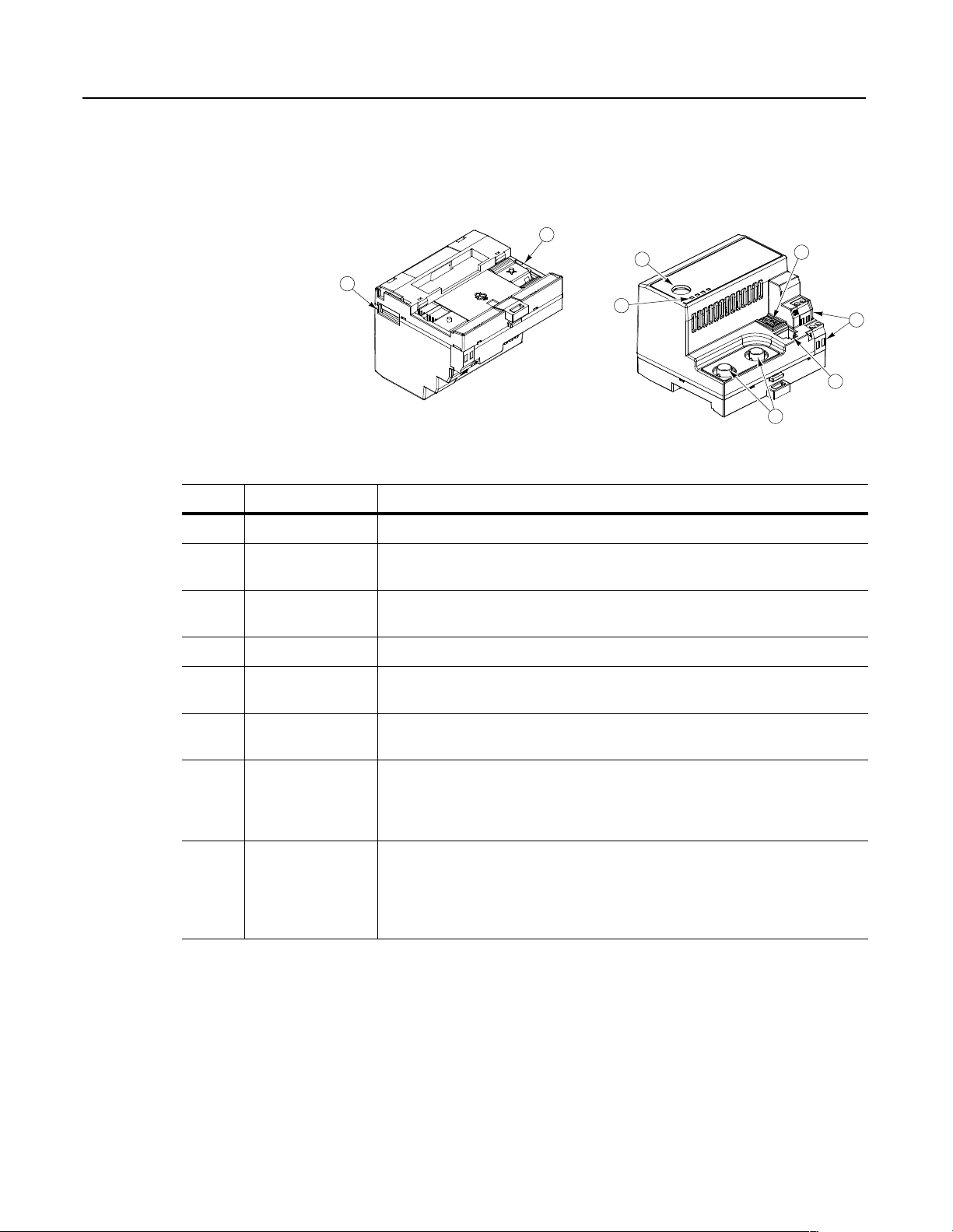
What Hardware Is Included?
Number Part Description
1 DIN Rail Mount Securely attaches and electronically grounds the module to the DIN rail.
2 ControlNet Coax
Connections
Figure 1.2 and the table below illustrate and list the main parts of the
1203-CN1 ControlNet communications module:
Figure 1.2
Parts of the Communications Module
1
4
8
3
Provide connections for ControlNet cable taps to allow either redundant or non-redundant
communications over the ControlNet network.
5
6
7
2
3 Bi-Color LEDs Indicate the status of each ControlNet media channel, of the SCANport connection, and of
the module. For more information, refer to Chapter 7, Troubleshooting.
4 SCANport Connection Provides a standard SCANport 8-pin circular mini-DIN connector for the SCANport cable.
5 ControlNet Node
Address Indicator
6 +24V DC Power
Connections
7 ControlNet Network
Access Port
8 RS-232 Serial Port Provides a connection for terminals capable of RS-232 serial communications. This por t can
Displays the ControlNet node address for the module. Use the push buttons to set the
address before applying power.
Provide for a +24V DC power supply connection. Multiple connections let you daisy chain
power through a group of modules placed close to each other.
Provides an RJ-45 connection for devices capable of communicating over ControlNet. The
module as well as other operational network devices can be accessed. A ControlNet network
access cable (1786-CP) and 1784-KTCX communication card, 1784-PCC communication
card, or 1770-KFC communication interface are required to use this por t.
be used to edit the module’s parameters, download a file needed to perform a flash to the
module’s operating code, and support devices that monitor and test the module. A 1203-SFC
serial cable and a PC running a terminal emulation program or a VT100-compatible terminal
are required to use this port.
Publication 1203-5.13 – February, 2002
Page 19

Overview 1-5
Overview of Setting Up the
1203-CN1 Module
Required Tools and Equipment
To set up the 1203-CN1 module, you must perform the following
tasks:
1. Install the module. Refer to Chapter 2, Installation.
2. If desired, configure the module’s parameters. Refer to Chapter 3,
Getting Started.
3. Configure the module on the ControlNet network. Refer to
Chapter 4, Configuring a Controller to Communicate with the
1203-CN1 Module.
To install and configure a 1203-CN1 module, you need the following
equipment:
• Grounding wrist strap (shipped with the module).
• 1203-CN1 ControlNet communications module.
• 35 x 7.5 mm DIN rail A (Allen-Bradley part number (199-DR1;
46277-3; EN 50022).
• 1/8 in. (3.2 mm) flathead screwdriver.
• Blunt, pointed instrument (not pen or pencil) for setting the node
address.
•Ohm meter.
• Appropriate cables for SCANport and ControlNet connections.
Refer to Chapter 2, Installation, for more information.
• 1203-SFC serial cable.
• Either a PC running a Windows™ terminal emulation program
(e.g., HyperTerminal) or a VT100-compatible terminal.
• PC that is:
– Running RSNetWorx™, RSLogix5™, and RSLinx™.
– Connected to the ControlNet network using a 1784-KTCX
card, 1784-PCC card, or 1770-KFC adapter.
Publication 1203-5.13 – February, 2002
Page 20

1-6 Overview
Notes:
Publication 1203-5.13 – February, 2002
Page 21

Installation
Chapter
2
Chapter Objectives
Required Tools and Equipment
Chapter 2 provides the information that you need to install the
1203-CN1 ControlNet communications module. This information
includes:
• A list of tools and equipment needed for the installation.
• A discussion of available cables for SCANport and ControlNet
connections.
• Instructions for installing the module.
• Instructions for removing the module.
After installing the module, refer to Chapter 3, Getting Started, for
procedures on how to configuring the module’s parameters and refer
to Chapter 4, Configuring a Controller to Communicate with the
1203-CN1 Module, for information on configuring the module on the
ControlNet network.
To install your 1203-CN1 module, you will need the following tools
and equipment:
• Grounding wrist strap.
• 1203-CN1 ControlNet communications module.
Selecting Cables
• 35 x 7.5 mm DIN rail A (Allen-Bradley part number 199-DR1;
46277-3; EN 50022).
• 1/8 in. (3.2 mm) flathead screwdriver.
• Blunt, pointed instrument (not pen or pencil) for setting the node
address.
• Appropriate cables for SCANport and ControlNet connections.
Refer to the Selecting Cables section in this chapter.
•Ohm meter.
To connect the 1203-CN1 module to the SCANport product and the
ControlNet network, you must select an appropriate SCANport cable
and one or two ControlNet cable tap(s). Use the following
information to select appropriate cables for each connection.
Publication 1203-5.13 – February, 2002
Page 22

2-2 Installation
SCANport Cables
When selecting the SCANport cable to connect the module to the
SCANport product, you need to:
• Use an Allen-Bradley SCANport cable. Refer to the table below.
Male to Male Connection
Length Catalog Number Length Catalog Number
1/3 m 1202-C03 1/3 m 1202-H03
1 m 1202-C10 1 m 1202-H10
3 m 1202-C30 3 m 1202-H30
9 m 1202-C90 9 m 1202-H90
➀
For most installations, a male-to-male connection on the cable is required.
➀
Male to Female Connection
• Do not exceed 10 meters (33 feet) of cable between the
SCANport product and module.
• Keep SCANport cables away from high power cables to guard
against introducing noise into your system.
ControlNet Cable Taps
A tap connects a node on the ControlNet network, such as a module,
to the cable system via an integral 1 m (39.6 in.) drop cable. When
selecting a tap to connect the module to the ControlNet network, you
need to:
• Determine if your network uses a redundant media system. If so,
you will need two taps.
• Use one or two Allen-Bradley tap(s). Refer to the table below.
Type Catalog Number
Straight T-Tap 1786-TPS
Straight Y-Tap 1786-TPYS
Right-Angle T-Tap 1786-TPR
Right-Angle Y-Tap 1786-TPYR
For more information on ControlNet taps and ControlNet networks,
refer to Publication 1786-6.2.1, ControlNet Cable System Planning
and Installation Manual.
Publication 1203-5.13 – February, 2002
Page 23

Installation 2-3
Electrostatic Discharge
Precautions
Please read the following safety precautions carefully before
installing the 1203-CN1 module
ATTENTION: The 1203-CN1 ControlNet
communications module contains ESD (Electrostatic
!
Important: You must wear a grounding wrist strap that is properly
grounded when you handle the 1203-CN1 module.
Discharge) sensitive parts. Static control precautions
are required when installing, testing, or servicing this
module. Device malfunction may occur if you do not
follow ESD control procedures. If you are not familiar
with static control procedures, refer to Allen-Bradley
publication 8000-4.5.2, Guarding Against Electrostatic
Damage, or other applicable ESD protection handbook.
Publication 1203-5.13 – February, 2002
Page 24
2-4 Installation
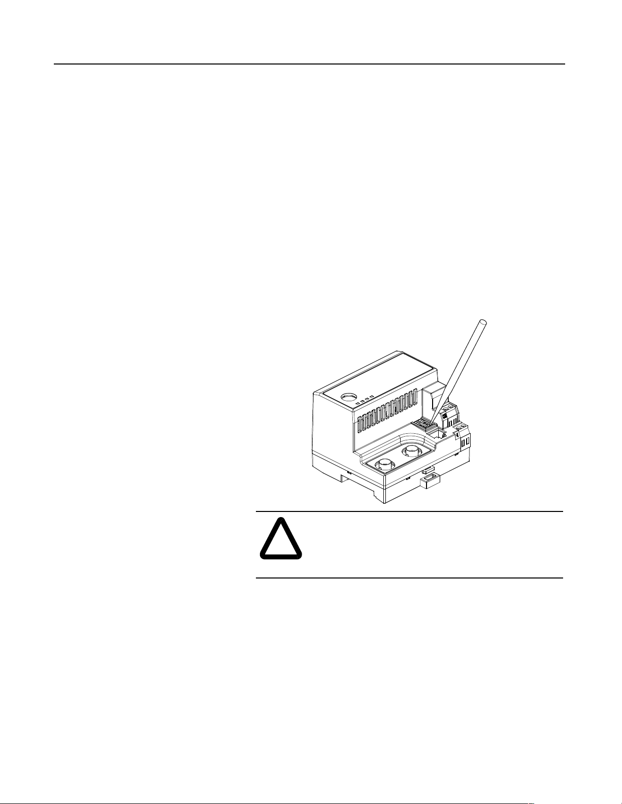
Installing Your 1203-CN1 Module
The following instructions explain how to physically install your
1203-CN1 module.
Important: To guard against device malfunction, you must wear a
grounding wrist strap when installing the 1203-CN1 module.
1. Set the module’s ControlNet node address by clicking the + or button to the desired value for each digit.
Important: Each node on the ControlNet network must have a
unique address.
Important: The node address must be set before power is applied
because the module uses the node address it detects when it first
receives power. To change a node address, you must set the new value
and then remove and reapply power to or reset the module.
Figure 2.1
Setting the Module’s Node Address
Publication 1203-5.13 – February, 2002
ATTENTION: When setting the node address, use a
blunt, pointed instrument. Do not use a pencil or pen
!
2. Ensure the DIN rail to which the module will be attached is
connected to an earth ground.
Important: If EMC compliance is required, the DIN rail should be
properly grounded inside a full metal enclosure. The enclosure should
also be properly connected to an earth ground.
because lead (graphite) or ink may damage the switch
assembly.
Page 25
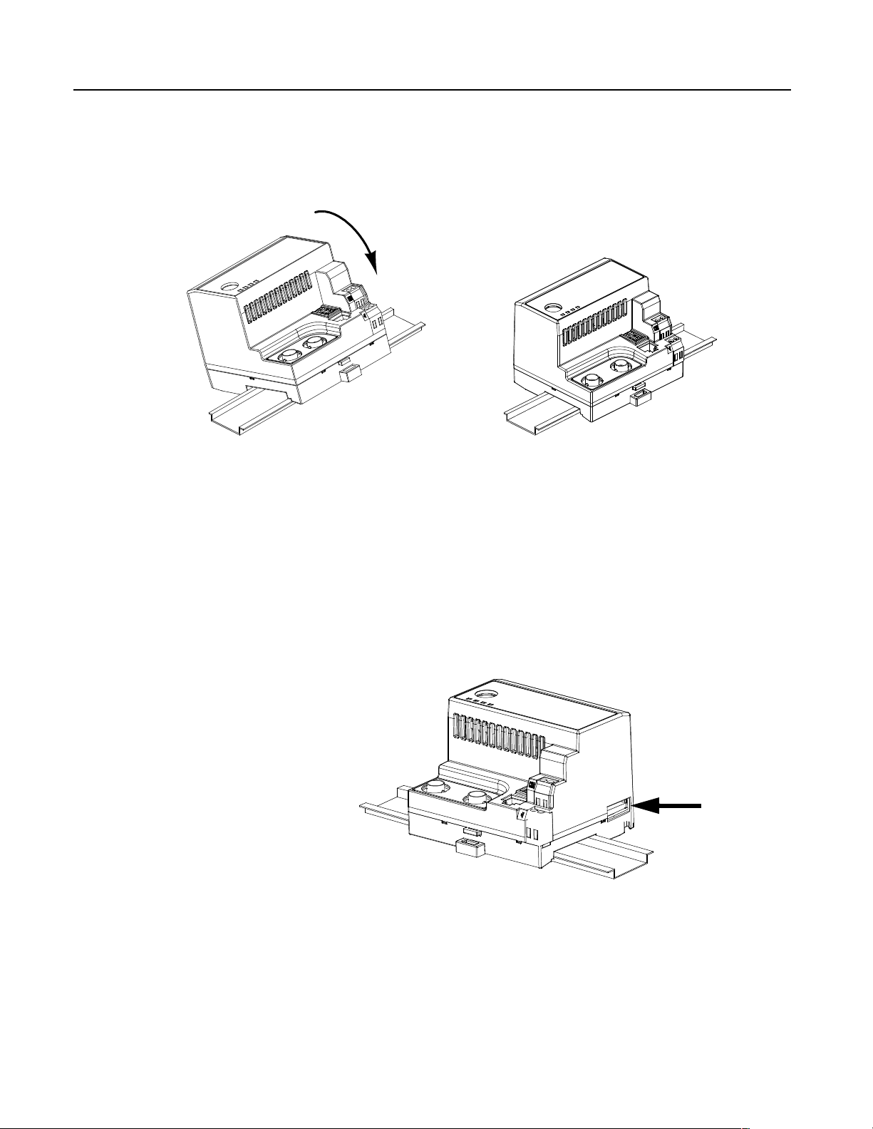
Installation 2-5
3. Hook the top lip of the module’s DIN rail mount onto the top of
the DIN rail and then rotate the module onto the DIN rail. You
will hear the module snap into a locked position.
Figure 2.2
Connecting the Module to the DIN Rail
4. Verify the module is correctly grounded to the DIN rail by using
an Ohm meter to measure between:
• DIN rail’s earth ground.
• Metal shell in the module’s RS-232 serial port.
If the reading is greater than 2 Ohms, you must reconnect the
module to the DIN rail, making sure it attaches securely.
Figure 2.3
Metal Shell of the Module’s RS-232 Serial Port
Publication 1203-5.13 – February, 2002
Page 26
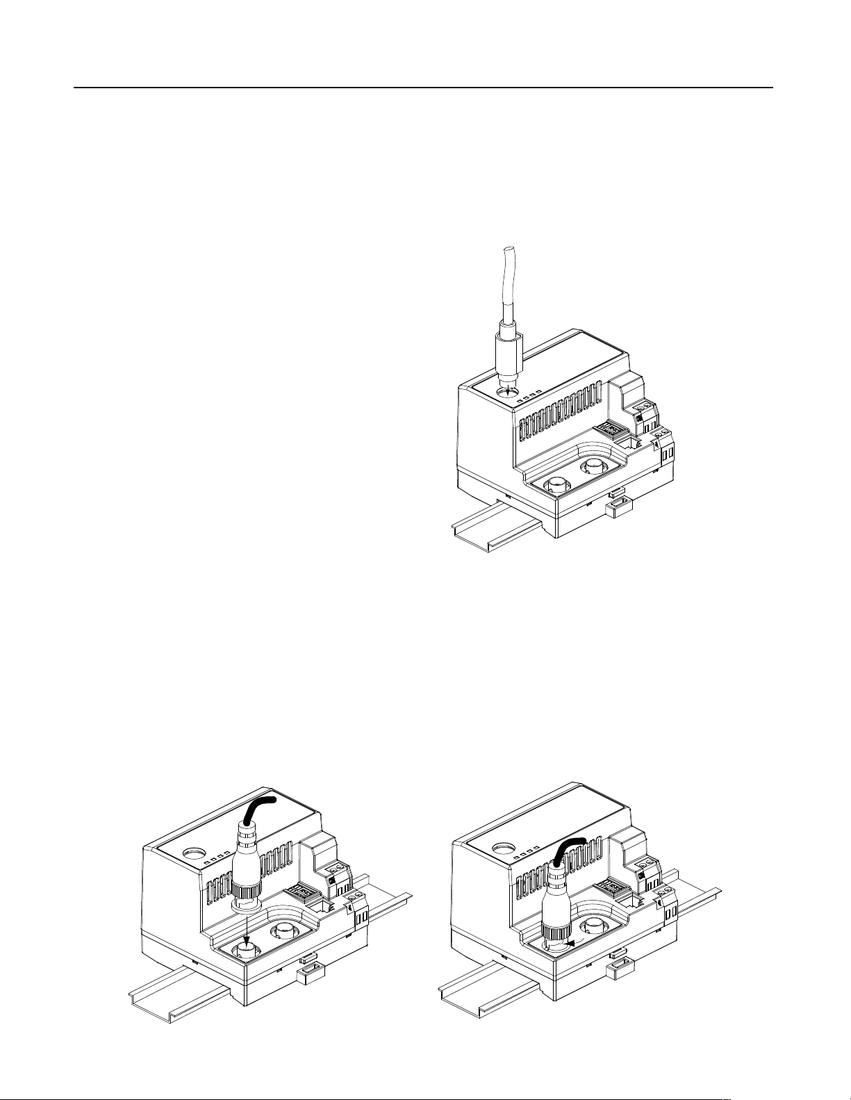
2-6 Installation
5. Connect the SCANport cable to the SCANport product and the
module.
To connect the cable to the module, align the pins on the cable
with the holes in the SCANport connection and then insert the
SCANport cable. The cable will click into a locked position.
Figure 2.4
Connecting the SCANport Cable to the Module
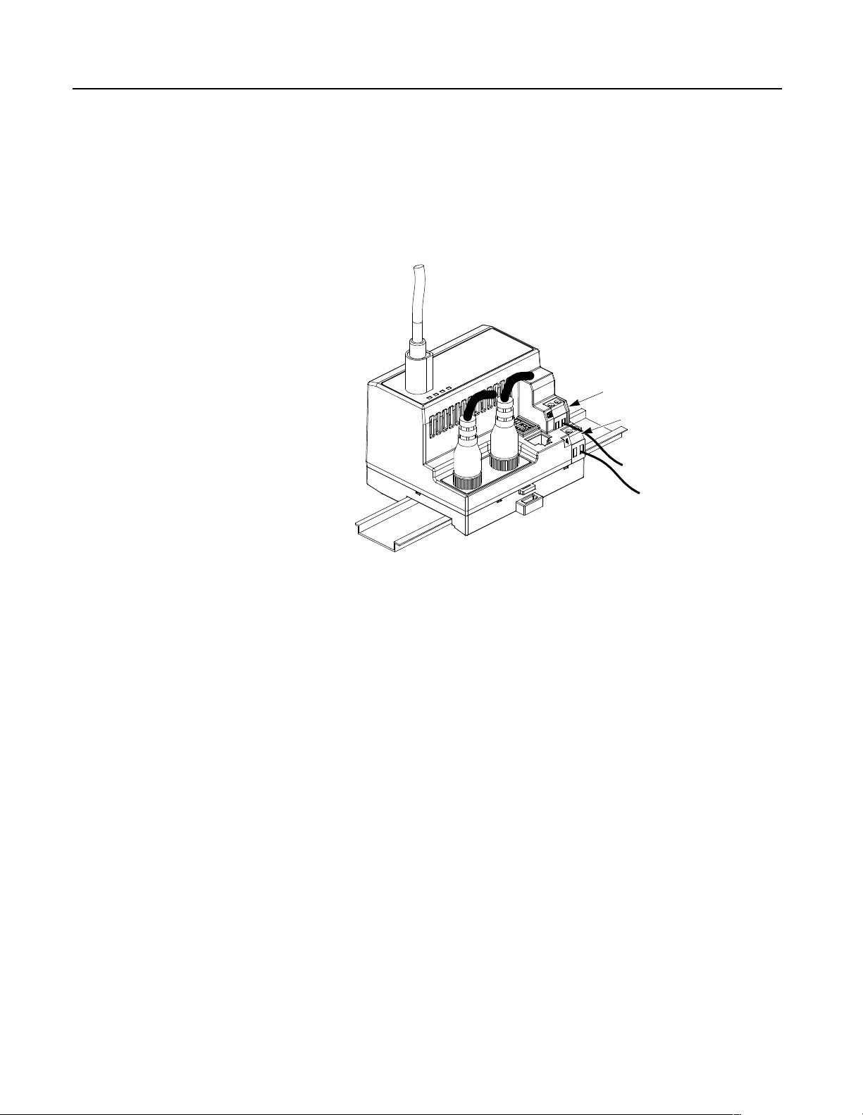
6. Connect the ControlNet cable tap(s) to the ControlNet media and
the module.
To connect the cable tap(s) to the module, twist each onto the
ControlNet Coax connection(s). You will hear the tap(s) click
into a locked position.
Important: Make sure you connect the Channel A cable to the
Channel A connection and the Channel B cable to the Channel B
connection.
Figure 2.5
Connecting a Straight ControlNet Tap to the Module
Publication 1203-5.13 – February, 2002
Page 27
Installation 2-7
7. Connect a +24V power supply. If necessary, loosen the screw to
insert the power supply connection and then re-tighten the screw.
Important: You can use the two sets of holes to daisy chain the
power supply between multiple 1203-CN1 modules placed close
together.
Figure 2.6
Connecting the Power Supply to the Module
COMMON
+ 24 VDC
The module is now physically installed. Its SCANport and
ControlNet LEDs are solid green, and its Module LED is flashing
green. (If your module’s LEDs differ, refer to Chapter 7,
Troubleshooting, for troubleshooting information.)
The flashing green Module LED means that the module is not yet
able to provide an interface between the ControlNet network and the
SCANport product. For it to do so, you must:
1. Configure, if necessary, the module by editing its parameters.
Refer to Chapter 3, Getting Started.
2. Configure the controller on the ControlNet network to recognize
and communicate with the module. Refer to Chapter 4,
Configuring a Controller to Communicate with the 1203-CN1
Module.
3. If desired, write a PLC Ladder Logic program to control the
SCANport product. Refer to Chapter 5, PLC Ladder Logic
Programming.
Important: The 1203-CN1 ControlNet communications module will
not communicate over ControlNet without being connected to a
SCANport product which is powered and operational.
Publication 1203-5.13 – February, 2002
Page 28
2-8 Installation
Removing the 1203-CN1 Module
If you want to remove the 1203-CN1 module, you need to:
Important: To guard against device malfunction, you must wear a
grounding wrist strap when removing the 1203-CN1 module.
1. Turn off the power supply to the module.
2. Disconnect all cables and the power supply from the module.
Important: To disconnect the SCANport cable, gently push in the
cable and then pull it out.
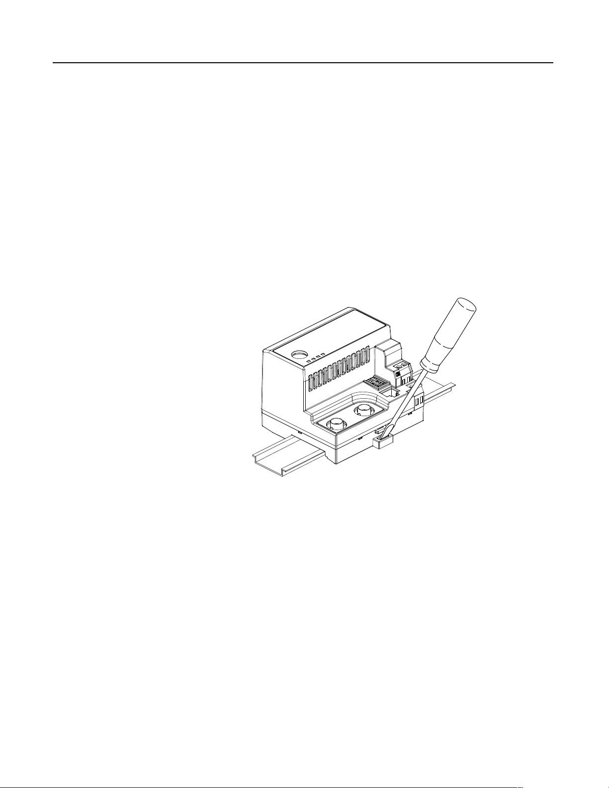
3. With a screw driver in the tab release, gently push its handle
towards the module to release the connection tab, and then pull
the module off of the DIN Rail.
Figure 2.7
Removing the Module from the DIN Rail
Publication 1203-5.13 – February, 2002
Page 29

Getting Started
Chapter
3
Chapter Objectives
Factory-Default Settings for the
1203-CN1 Module’s Parameters
Chapter 3 provides information that you need to configure the
1203-CN1 ControlNet Communications module. This includes:
• Information on the 1203-CN1 module’s default setting.
• Equipment needed to make a serial connection to the module.
• Instructions on how to connect a PC running terminal emulation
software or a VT100-compatible terminal to the module.
• Navigation techniques to use in the module’s software.
• Instructions for editing the module’s parameters.
• Instructions for displaying and clearing the module’s event queue.
• Instructions for displaying the modules I/O data.
• Instructions for displaying DF1 Protocol statistics.
• Instructions for viewing the module’s serial number.
• Instructions for performing a flash upgrade to the module.
The factory-default settings of the 1203-CN1 module enable the
following functions:
• 16-bit Logic Command/Status.
• 16-bit Reference/Feedback.
• If the PLC is put into program mode or the network fails, the
SCANport product will be faulted by the module.
• All datalinks are disabled.
• Baud rate is 9600.
If you wish to change any of these functions (e.g., Fault Configurable
inputs) or add more functions (e.g., datalinks), you must edit the
module’s parameters. To do so, refer to:
• Appendix B, 1203-CN1 Module Parameters, for detailed
information about each of the module’s parameters.
• Instructions in this chapter on establishing a serial connection.
• Instructions in this chapter on how to edit the parameters.
Publication 1203-5.13 – February, 2002
Page 30

3-2 Getting Started
Required Tools and Equipment
Electrostatic Discharge
Precautions
To make a serial connection to the module, you need the following:
• Grounding wrist strap.
• 1203-SFC serial cable.
• Either a PC running a Windows terminal emulation program
(e.g., HyperTerminal) or a VT100-compatible terminal.
Please read the following safety precautions carefully before making
a serial connection to the 1203-CN1 module
ATTENTION: The 1203-CN1 ControlNet
communications module contains ESD (Electrostatic
!
Discharge) sensitive parts. Static control precautions
are required when installing, testing, or servicing this
module. Device malfunction may occur if you do not
follow ESD control procedures. If you are not familiar
with static control procedures, refer to Allen-Bradley
publication 8000-4.5.2, Guarding Against Electrostatic
Damage, or other applicable ESD protection handbook.
.
Establishing a Serial Connection
with the 1203-CN1 Module
You must wear a grounding wrist strap that is properly grounded
when you handle the 1203-CN1 module.
The module’s software lets you do the following:
• Edit the module’s parameters.
• View its serial number.
• View its event queue.
• View its current I/O data.
• View DF1 statistics.
• Perform a flash upgrade.
To access its software, you must make a serial connection between the
module and either a PC running terminal emulation software or a
terminal. Refer to the following table:
If Using: Refer to Page
PC running terminal emulation software 3-3
VT100-compatible terminal 3-7
Publication 1203-5.13 – February, 2002
DriveExplorer (v.101 or higher) software can now also be used on
1203-CN1s that are v2.001 or higher. Do not use DriveExplorer
software with v1.xxx CN1s.
Page 31

Getting Started 3-3
Using a PC Running Terminal Emulation Software
A variety of terminal emulation programs can be used to establish a
serial connection to the module. The following instructions describe
how to establish the initial serial connection to the module using a PC
running Windows 95 HyperTerminal software. Future connections to
the module can use this same configuration by clicking the icon added
to the initial screen when the configuration is saved.
Important: If you are not using Windows 95 HyperTerminal, steps to
establish a serial connection may vary from the following steps.
1. Connect a 1203-SFC serial cable to your PC’s serial port and then
to the RS-232 serial port on the module.
Figure 3.1
Connecting the 1203-SFC Serial Cable to the Module’s RS-232 Serial Port
2. In the Start menu, select Programs, Accessories, and then
HyperTerminal. A HyperTerminal dialog box appears.
Figure 3.2
Example HyperTerminal Dialog Box
Publication 1203-5.13 – February, 2002
Page 32

3-4 Getting Started
3. Double-click HyperTrm.exe. The Connection Description
dialog box appears.
Figure 3.3
Example Connection Dialog Box
4. Enter a name in the Name field and select any icon in the Icon
field. In this example, we enter “1203-CN1” in the Name field.
5. Click OK. The Phone Number dialog box appears.
Figure 3.4
Example Phone Number Dialog Box
Publication 1203-5.13 – February, 2002
6. In the Connect Using field, select the appropriate
communications port (usually COM1 or COM2).
Page 33

Getting Started 3-5
7. Click OK. The Comm Properties dialog box appears.
Figure 3.5
Example Comm Properties Dialog Box
8. Select the following settings:
• 9600 in the Bits per second field.
If you have previously set the module’s Serial Port Rate
(Parameter 21) to enable 19200 bps, set the bps to 19200 in
this field.
• 8 in the Data bits field.
• None in the Parity field.
• 1 in the Stop bits field.
• None in the Flow Control field.
9. Click OK. A blank HyperTerminal screen appears.
Publication 1203-5.13 – February, 2002
Page 34

3-6 Getting Started
10. In the File menu, select Properties. The Properties dialog box
appears.
Figure 3.6
Properties Dialog Box
11. Click the Settings tab.
12. In the Function, arrow, and ctrl keys act as box, verify
Ter mi na l ke y s is selected.
13. In the Emulation field, verify VT100 is selected.
14. Click OK.
15. In the File menu, select Save. The configuration is saved and the
icon you selected will appear in the initial HyperTerminal
window next time you start HyperTerminal.
Figure 3.7
Example Initial HyperTerminal Window
Publication 1203-5.13 – February, 2002
Important: Next time you need to make a connection to the module,
double-click the icon just created. In Figure 3.7, double-clicking the
1203-CN1.ht icon would re-establish the connection to the module.
Page 35

Getting Started 3-7
16. Press the Enter key. The main menu of the1203-CN1 ControlNet
to SCANport Adapter application appears.
Figure 3.8
Main Menu
You now have access to the module’s software. Go to the Navigation
Techniques section on page 3-8 for more information on using it.
Using a VT100-Compatible Terminal
Important: If you are using a PC, skip this section.
The following instructions describe how to establish a serial
connection to the module using a VT100-compatible terminal.
1. Connect a 1203-SFC serial cable to your terminal and then to the
RS-232 serial port on the module. Refer to Figure 3.1.
2. Start your terminal.
3. Select the following settings:
• 9600 in the Bits per second field.
If you have previously set the module’s Serial Port Rate
(Parameter 21) to enable 19200 bps, set the bps to 19200.
• 8 in the Data bits field.
• None in the Parity field.
• 1 in the Stop bits field.
• None in the Flow Control field.
Publication 1203-5.13 – February, 2002
Page 36

3-8 Getting Started
4. Press the Enter key. The main menu of the 1203-CN1 ControlNet
to SCANport Adapter application appears.
Refer to the Navigation Techniques section in this chapter for
information on navigating in the software.
Figure 3.9
Main Menu
Navigation Techniques
You now have access to the module’s software. Go to the Navigation
Techniques section on page 3-8 for more information on using it.
To perform any of the functions in the software (e.g., editing
parameters), you need to know the following navigation techniques:
Press: To
1, 2, 3, 4, 5, 6, 7, 8, 9, 0 Select an option in the Main Menu (1 – 5) or enter a value
for a parameter in the Parameter screen (0 – 9).
Escape Return to Main Menu or abort changes to a parameter.
Down Arrow View the next parameter.
Up Arrow View the previous parameter.
Right Arrow
Left Arrow
Enter Save a value for a parameter.
➀
In the
Fault Config Logic Command
navigate through the 16 bits.
View the next value for a parameter.
View the previous value for a parameter.
parameter (11), the right and left arrow keys let you
➀
➀
Publication 1203-5.13 – February, 2002
Page 37

Getting Started 3-9
Editing Parameters in the 1203-CN1
Module
The 1203-CN1 module has many configurable parameters. Refer to
Appendix B, 1203-CN1 Module Parameters, for a detailed list. If you
do not want to use the module’s default settings, edit its parameters.
Important: You may also edit parameters over the ControlNet
network using PCCC or emulated block transfer messages. Refer to
Chapter 6, Using Messages, for information on and examples of
messaging and refer to the appendixes for information needed to build
messages.
To edit parameters using a serial connection, you need to:
1. Establish a serial connection to access the module’s software.
Refer to the Establishing a Serial Connection with the 1203-CN1
Module section earlier in this chapter.
2. Press 1 to select 1> Display Parameters. The first parameter
appears on the bottom of the screen.
Figure 3.10
Example Display Parameters Screen
Important: If you know the number of the parameter you intend to
edit, press 2 to select 2> Enter Specific Parameter Number and
then enter the parameter number.
3. If necessary, scroll through the list of parameters by pressing the
Up Arrow or Down Arrow key.
Publication 1203-5.13 – February, 2002
Page 38
3-10 Getting Started
4. Edit parameters as necessary using the Left Arrow and Right
Arrow keys. Refer to Navigation Techniques earlier in this
chapter for information on changing values. Refer to Appendix B,
1203-CN1 Module Parameters, for valid values.
5. If necessary, reset power to the module by enabling the Reset
Adapter parameter (22). Refer to Appendix B, 1203-CN1 Module
Param et ers , to see if the parameter you changed requires the
module to be reset in order to take effect.
Displaying and Clearing the Event
Queue in the 1203-CN1 Module
If an unexpected problem occurs with the module, you may need to
check the event queue to view events that have happened in the
module. Follow these instructions:
1. Establish a serial connection to access the module’s software.
Refer to the Establishing a Serial Connection with the 1203-CN1
Module section earlier in this chapter.
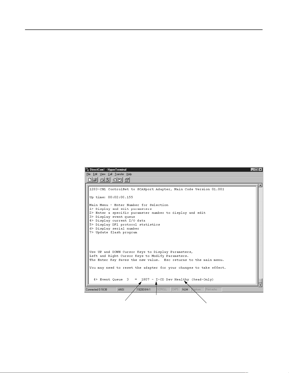
2. Press 3 to select 3> Display event queue. The event queue
appears.
Figure 3.11
Example Event Queue
Publication 1203-5.13 – February, 2002
Internal
Fault ID
Level of Fault
I = information
W = warning
S = severe
F = fatal
Description
Page 39
Getting Started 3-11
3. Scroll through the list of Event Queue parameters by pressing the
Up Arrow or Down Arrow key.
Number Name Description
1 Clr Event Queue Enable = Clears the event queue.
Ready = Leaves the event queue as is.
2 – 33 Event Queue 1 – Event Queue 32 Event in the event queue. Most recent event is listed in Event Queue 1.
4. If desired, clear the current fault in the adapter by setting Clr
Event Queue (1) to Enable and pressing the Enter key.
Important: The Fault is cleared in the module and a “Clear Fault”
event is added to the Event Queue.
5. Press the Escape key to return to the main menu.
Displaying the 1203-CN1 module’s
Current I/O Data
You may need to do diagnostic testing to verify I/O data is passing
through the module. To view the I/O data transmitted through the
module, follow these instructions:
1. Establish a serial connection to access the module’s software.
Refer to the Establishing a Serial Connection with the 1203-CN1
Module section earlier in this chapter.
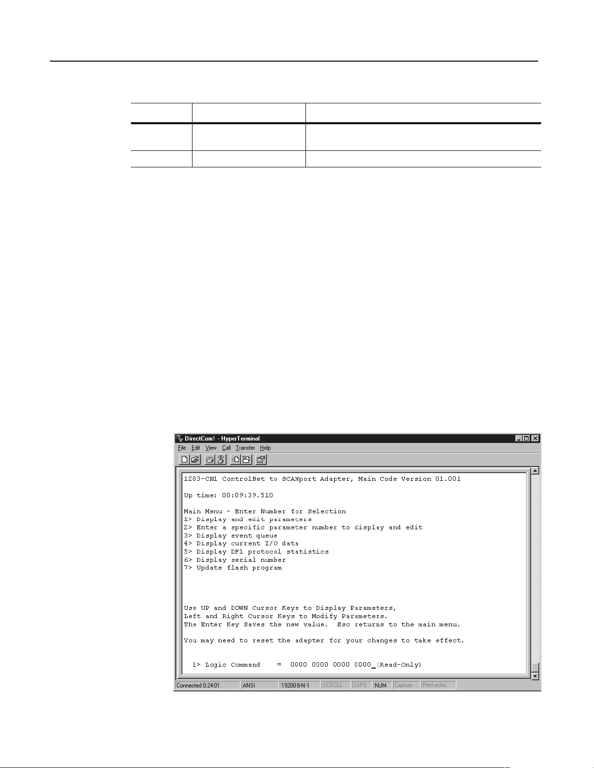
2. Press 4 to select 4> Display current I/O data. The I/O Data
screen appears.
Figure 3.12
Example I/O Data Screen
Publication 1203-5.13 – February, 2002
Page 40

3-12 Getting Started
Number Name Description
5 – 20 Data A1 In Val – Data D2 Out Val Data going to (Input) or coming from (Output) the SCANport device
3. Scroll through the list of I/O Data parameters by pressing the Up
Arrow or Down Arrow key.
1 Logic Command Buffer for Logic Command data
2 Logic Status Buffer for Logic Status data
3 Reference Data Buffer for Reference data
4 Feedback Data Buffer for Feedback data
4. Press the Escape key to return to the main menu.
Displaying the DF1 Protocol
Statistics in the 1203-CN1 Module
If you are working with DF1 communications, you may need to know
how the module is using DF1 communications. To view statistics on
DF1 communications, follow these directions:
1. Establish a serial connection to access the module’s software.
Refer to the Establishing a Serial Connection with the 1203-CN1
Module section earlier in this chapter.
2. Press 5 to select 5> Display DF1 protocol statistics. The DF1
Protocol screen appears.
Figure 3.13
Example DF1 Protocol Statistic
Publication 1203-5.13 – February, 2002
Page 41

Getting Started 3-13
3. Scroll through the list of DF1 statistic parameters by pressing the
Up Arrow or Down Arrow key.
Number Name Description
1 Clear DF1 Counts Ready = Accept default
Enable = Reset all status parameters
2 DF1 Packets Sent Total number of DF1 packets sent by the module
3 DF1 Packets Rcvd Total number of DF1 packets received by the module
4 Undelivered Msgs Total number of messages sent that were not acknowledged
5 ENQ Sent Total number of inquiries sent by the module
6 ENQ Rcvd Total number of inquiries received by the module
7 NAKs Received Total number of NAKs received by the module
8 NAK Bad Packet Total number of NAKs received by the module
9 NAK No Memory Total number of NAKs sent by the module because the previous
command did not yet complete and there was no place to save the new
command
10 Duplicate Msgs Total number of messages received by the module with the TNS number
4. If desired, reset the current DF1 protocol statistics by setting
Clear DF1 Counts to Enable and pressing the Enter key.
Viewing Your 1203-CN1 Module’s
Serial Number
5. Press the Escape key to return to the main menu.
Each 1203-CN1 module has a unique serial number. To view the
serial number, follow these instructions:
1. Establish a serial connection to access the module’s software.
Refer to the Establishing a Serial Connection with the 1203-CN1
Module section earlier in this chapter.
2. Press 6 to select 6> Display serial number. The serial number
for your communications module appears.
3. Press Escape to return to the Main Menu.
Publication 1203-5.13 – February, 2002
Page 42

3-14 Getting Started
Performing a Flash Upgrade to the
1203-CN1 Module
To upgrade the 1203-CN1 module’s flash firmware using the
module’s serial port, you need to perform a flash upgrade.
Important: To perform a flash upgrade to your module’s firmware,
you must use a PC running terminal emulation software.
Important: To exit the flash upgrade option before the download has
started, simultaneously press the Control and X keys.
ATTENTION: Exiting the flash upgrade procedure
once the download has begun can cause the module to
!
To perform a flash upgrade, you need to:
1. Obtain the software file that contains the upgrade and record its
location.
2. Establish a serial connection to access the module’s software.
Refer to the Establishing a Serial Connection with the 1203-CN1
Module section earlier in this chapter.
become inoperable. If the module becomes inoperable,
you must perform and complete a flash upgrade to fix
the module.
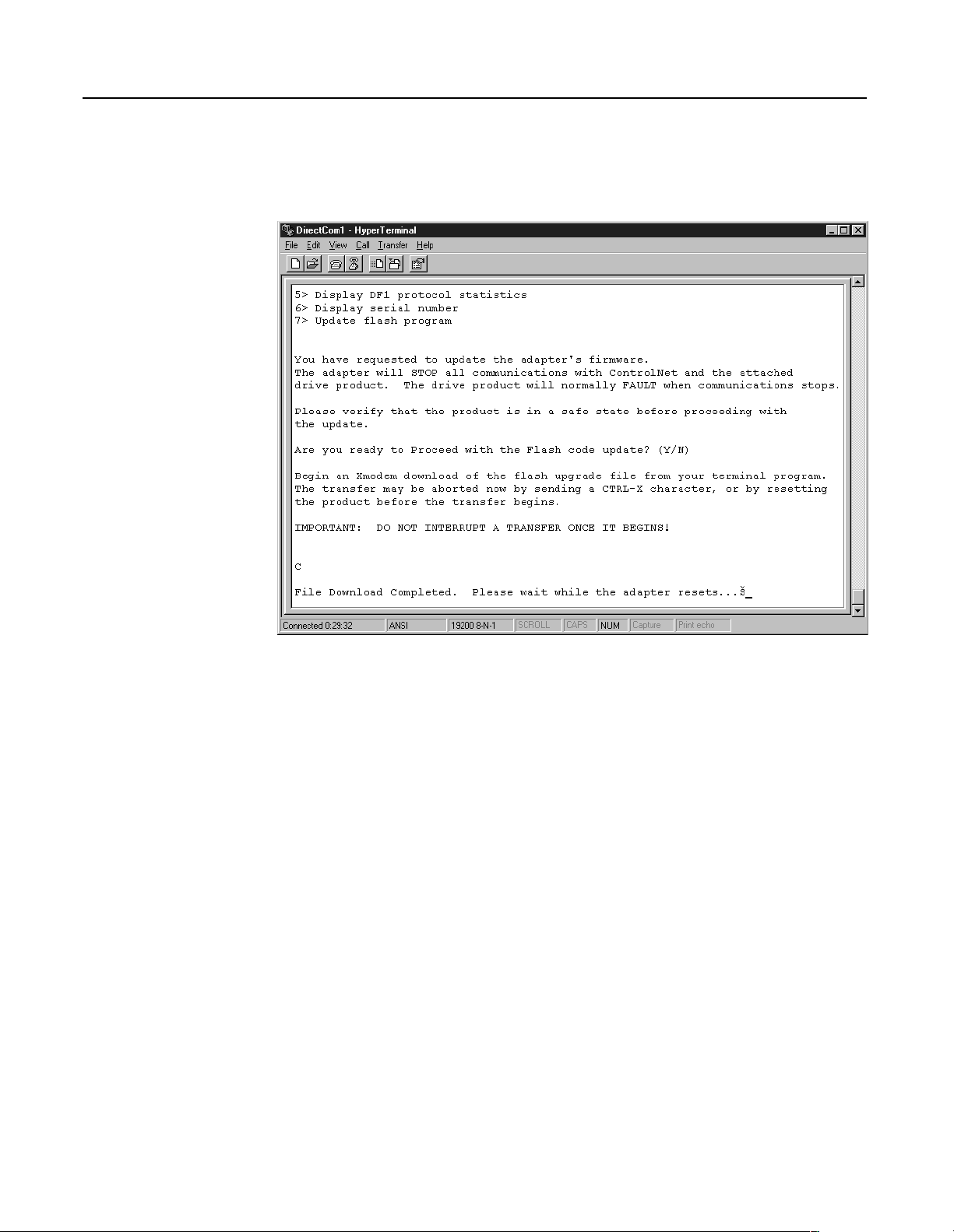
3. Press 7 to select 7> Update Flash Program. The following
screen appears.
ATTENTION: Hazard of personal injury or death
exists when stopping a drive to perform a flash upgrade.
!
When you perform a flash upgrade, the drive will fault
and stop the motor if the drive is receiving control data
from the 1203-CN1 module. Make sure the motor will
stop safely or the drive will receive control data from
an alternate source before beginning a flash upgrade.
Publication 1203-5.13 – February, 2002
Page 43

Figure 3.14
Initial Update Flash Program Screen
Getting Started 3-15
4. Press Y to verify that you want to perform a flash upgrade when
prompted.
5. In the Trans fer menu, select Send File. The Send File dialog
box appears.
Figure 3.15
Send File Dialog Box
6. In the Filename field, select the file that contains the flash
upgrade.
Important: You can click the Browse button to locate the file that
contains the flash upgrade.
7. In the Protocol field, select Xmodem.
Publication 1203-5.13 – February, 2002
Page 44
3-16 Getting Started
8. Click Send. A dialog box appears to report the flash is in
progress. When the flash is complete, a message appears to tell
you the download is complete and the module will reset itself.
Figure 3.16
Message Reporting the Flash Is Complete
The module resets itself, and then the Main menu appears. You must
clear the drive’s fault in order to restart the drive.
Publication 1203-5.13 – February, 2002
Page 45

Chapter
4
Configuring a Controller to Communicate
with the 1203-CN1 Module
Chapter Objectives
What is RSNetWorx?
Chapter 4 provides instructions for configuring your controller to
communicate with the 1203-CN1 ControlNet communications
module. This allows the product connected to the 1203-CN1 module
to be an active node on the ControlNet network. This chapter provides
information on:
•RSNetWorx.
• Equipment and software needed for the configuration.
• Configuring a controller to communicate with the 1203-CN1
module.
This chapter assumes you have experience using RSNetWorx to
configure a ControlNet network.
RSNetWorx for ControlNet is a 32-bit Windows application program
that lets you configure ControlNet networks. Using a graphical
representation of your network, you can configure network-wide
parameters and the network-wide schedule.
After installing and configuring the module, you must use
RSNetWorx to configure the controller to recognize and
communicate with the module.
Required Equipment and Software
For more information on RSNetWorx, refer to:
• Getting Results with RSNetWorx for ControlNet, Doc. ID
9399-CNETGR.
• Hardware Configuration Reference Guide, Doc. ID
9399-HDWAREREF.
• RSNetWorx online help.
Before configuring the controller, your PC must be:
• Running RSNetWorx and RSLinx applications. Refer to
http://www.software.rockwell.com for more information on these
products.
• Connected to and communicating with the ControlNet network
using a 1784-KTCX card, 1784-PCC card, or 1770-KFC adapter.
Publication 1203-5.13 – February, 2002
Page 46
4-2 Configuring a Controller to Communicate with the 1203-CN1 Module
Configuring a Controller to
Communicate with the 1203-CN1
Module
For the controller on the ControlNet network to transmit control I/O
and/or messages to the 1203-CN1 module, you must configure it to
recognize and communicate with the 1203-CN1 module.
These instructions describe how to use RSNetWorx to configure a
new ControlNet network in online mode. The main steps in the
configuration are:
• Using online mode in RSNetWorx.
• Mapping the 1203-CN1 module to the network.
• Verifying the network properties.
Important: RSNetWorx 1.6 and RSLinx 2.0.82 were used for these
instructions. If you are using other versions, you may notice
differences between these instructions and your screens.
Using Online Mode in RSNetWorx
It is easiest to configure the ControlNet network online because you
can view a graphical representation of your network in RSNetWorx.
Follow these instructions:
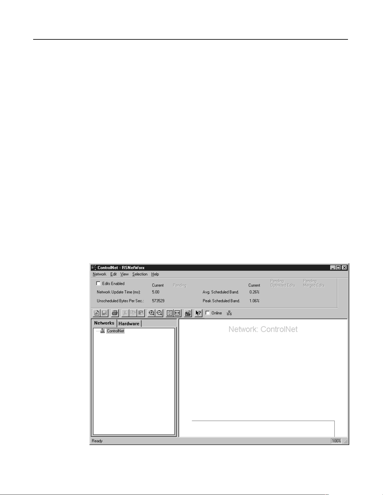
1. Start RSNetWorx. The RSNetWorx screen appears.
Figure 4.1
RSNetWorx Screen
Publication 1203-5.13 – February, 2002
Page 47

Configuring a Controller to Communicate with the 1203-CN1 Module 4-3
2. Click the Online box. RSLinx starts in the background to provide
a communications interface and then the Browse for Network
dialog box appears.
Figure 4.2
Example Browse for Network Dialog Box
3. If available, click the Autobrowse box.
4. If necessary, click the plus sign to view the available networks.
Figure 4.3
Example Browse for Network Dialog Box with Available Networks Displayed
Publication 1203-5.13 – February, 2002
Page 48

4-4 Configuring a Controller to Communicate with the 1203-CN1 Module
5. Select your ControlNet network and click OK. A graphical
representation of your network appears.
Figure 4.4
Example Network Displayed in RSNetWorx
Publication 1203-5.13 – February, 2002
Important: Note the following about our example:
• In Figure 4.4, Node 1 is the controller (PLC-5), Node 4 is the
SCANport product to which the 1203-CN1 module is
connected, and Node 20 is the PC we are using to configure
the network.
• The 1203-CN1 module is transparent on the ControlNet
network, so an icon for the SCANport product connected to it
is displayed in RSNetWorx. In our example, we used a 1305
drive and set the node address on the 1203-CN1 module to
Node 4.
• Above the icons are plus flags that indicate the devices are
not configured for the network.
Page 49

Configuring a Controller to Communicate with the 1203-CN1 Module 4-5
6. In the Network menu, select Actions and then Configurations
List. The ControlNet Configuration dialog box appears.
Figure 4.5
Example ControlNet Configuration Dialog Box
7. Identify the device(s) that need(s) to be mapped to the network.
The Current Configuration list (blank in Figure 4.5) shows the
devices configured on the ControlNet network. The Network
Configuration list shows devices on the network. Because we are
creating a new ControlNet network from scratch in our example,
no devices are currently configured. Your network may already
have devices configured on it.
The only device that we will need to map to the network is the
1203-CN1 module. The other devices (PLC-5/40
®
) and
(1784-KTCX) do not need to be configured on the network.
8. Click OK to close the dialog box. The RSNetWorx screen
reappears.
You are now in online mode and know which device(s) need to be
mapped to the network.
Publication 1203-5.13 – February, 2002
Page 50

4-6 Configuring a Controller to Communicate with the 1203-CN1 Module
Mapping the 1203-CN1 Module to the ControlNet Network
You must configure the 1203-CN1 module on the ControlNet network
so that the controller can communicate with it. Follow these
instructions:
1. Click the Edits Enabled box.
Important: If the Online/Offline Mismatch dialog box appears,
click OK to use the online data. If prompted to save, save the data.
2. Right-click on the controller’s icon (PLC-5) and select
ControlNet Configuration. The ControlNet Configuration
screen appears.
Figure 4.6
Sample ControlNet Configuration Screen
Publication 1203-5.13 – February, 2002
Page 51

Configuring a Controller to Communicate with the 1203-CN1 Module 4-7
3. Select the line with the SCANport product you want to configure.
Important: You can verify that you’ve selected the correct line by
making sure it has the same node number that you set for the module
during the installation.
4. In the Insert menu, select Device Connection.
Figure 4.7
Example of the Product Line after Drive Connection Is Selected
5. Fill in each of the following fields on the bottom of the screen
with unique, valid N-file numbers for the controller you are using.
(Each N-file number must be unique.)
• Diagnostics
• Status
• Configuration
• Data Input
•Data Output
6. Note the N-file numbers you filled in the fields. You will need
them to develop a ladder logic program.
Publication 1203-5.13 – February, 2002
Page 52

4-8 Configuring a Controller to Communicate with the 1203-CN1 Module
7. Double-click the Input Size field in your product’s row and select
the appropriate size.
Valid sizes are 2, 4, 6, 8, and 10. To determine the size, add 2 if
Control I/O is enabled and add 2 for each datalink that is enabled.
For example, if Control I/O data and all datalinks are enabled, the
size would be 10.
8. Double-click the Output Size field in your product’s row and
select the appropriate size. This Output size should be the same
value as the Input size.
9. Click the RPI(ms) field in your product’s row and enter the
desired time for required packet interval.
Important: Note the value you enter. Ensure that this value is equal
to or greater than the value you will set later in the Network Update
Time field in the Network Properties: ControlNet dialog box.
Important: The actual packet interval (API) may vary from the
requested packet interval (RPI).
Important: The rate at which a SCANport product reports
information to the module varies based on the number of datalinks
enabled, the number of peripherals attached to the product, and the
type of product.
Figure 4.8
Example Configuration with Size Inputs Set for Control I/O Data Only
Publication 1203-5.13 – February, 2002
Page 53

Configuring a Controller to Communicate with the 1203-CN1 Module 4-9
10. In the Configuration menu, select Auto Map and then All
Entries. Addresses are put in the Input Address and Output
Address columns.
Figure 4.9
Example Configuration
Important: If you want to map the addresses manually, click in the
correct field and then enter the address. Make sure you insert a valid
address. Refer to the online help for information on manually
mapping an address.
Publication 1203-5.13 – February, 2002
Page 54

4-10 Configuring a Controller to Communicate with the 1203-CN1 Module
11. In the Network menu, select Save. The Save Configuration
dialog box appears.
Figure 4.10
Save Configuration Dialog Box
12. Click OK. The Save As dialog box may appear.
Important: If the ControlNet Services dialog box appears with a
warning about the MAX scheduled node being set too low, click OK.
You will correct the problem later while verifying network properties.
Figure 4.11
Save As Dialog Box
Publication 1203-5.13 – February, 2002
13. In the File name field, enter a name for the file and then click
Save.
Clicking Save saves the configuration to a file on the PC and
downloads the configuration to the controller on the network.
Page 55

Configuring a Controller to Communicate with the 1203-CN1 Module 4-11
14. In the Network menu, select Exit. The ControlNet
Configuration screen closes and the RSNetWorx screen
reappears.
Figure 4.12
Example RSNetWorx Screen with Configured Network
Important: The icon for the SCANport product connected to the
1203-CN1 module (node 4 in Figure 4.12) should appear with a gray
flag on it to indicate it is configured. The ≠ sign may appear in the
flag to indicate your drive’s firmware revision is not matching that in
RSNetWorx. If so, proceed.
Publication 1203-5.13 – February, 2002
Page 56

4-12 Configuring a Controller to Communicate with the 1203-CN1 Module
15. In the Network menu, select Action and then Configuration
List. The ControlNet Configuration dialog box appears.
Figure 4.13
Example ControlNet Configuration Dialog Box
16. Verify all devices are configured on your network.
Devices configured on the network will appear in the Current
Configuration list. Figure 4.13 shows all devices are configured
on our example network.
17. Click OK to close the dialog box.
When all devices are mapped to the network, you must verify that
network properties are set correctly.
Publication 1203-5.13 – February, 2002
Page 57

Configuring a Controller to Communicate with the 1203-CN1 Module 4-13
Verifying Network Properties
For your network to function properly, you must set the correct
properties. To verify that the correct properties are set, follow these
instructions:
1. Click the Edits Enabled box.
2. In the Network menu, select Properties. The Network
Properties: ControlNet dialog box appears.
Figure 4.14
Network Parameters Tab of the Network Properties: ControlNet Dialog Box
3. In the Network Parameters tab, verify:
• The value in the Network Update Time(ms) field is 5 or
greater.
Important: Do not set the Network Update Time lower than 5 ms.
Important: Set the Network Update Time equal to or lower than the
RPI times set for the devices on the network.
• The number in the Max Scheduled Address field is higher
than or equal to the highest node number with which you’ll
do I/O.
• The number in the Max Unscheduled Address field is
higher than or equal to the highest node number on the
network.
• The correct type of media redundancy is selected in the
Media Redundancy field.
Publication 1203-5.13 – February, 2002
Page 58

4-14 Configuring a Controller to Communicate with the 1203-CN1 Module
4. If a special media configuration is required (e.g., repeater), select
the Media Configuration tab and make the appropriate changes.
Refer to the online help for more information.
Figure 4.15
Media Configuration Tab
5. If desired, select the General tab and enter a name and
description for the network.
Figure 4.16
Example General Tab
Publication 1203-5.13 – February, 2002
Page 59

Configuring a Controller to Communicate with the 1203-CN1 Module 4-15
6. Click OK.
7. In the Network menu, select Save to save the properties and
download them to the PLC.
The module is now mapped on the network and the controller will
communicate with it. If all mapped devices are present and
operational:
• I/O and ControlNet Channel LEDs on the controller will be solid
green.
• ControlNet LED(s) on the 1203-CN1 will be solid green.
For information on how to create a PLC ladder logic program to
transmit control data to the SCANport product attached to the
1203-CN1 module, refer to Chapter 5, PLC Ladder Logic
Programming.
Publication 1203-5.13 – February, 2002
Page 60

4-16 Configuring a Controller to Communicate with the 1203-CN1 Module
Notes:
Publication 1203-5.13 – February, 2002
Page 61

Chapter
PLC Ladder Logic Programming
5
Chapter Objectives
What Is RSLogix5?
Chapter 5 provides information needed to create the PLC Ladder
Logic program that the controller will use to transmit control I/O and
messages to and from the SCANport product. This information
includes:
• Discussion of PLC ladder logic programs.
• Equipment and software needed to create a PLC Ladder Logic
program.
• Example PLC ladder logic program to control the drive.
This chapter assumes you already have experience creating ladder
logic programs using RSLogix5.
RSLogix5 software lets you create the ladder logic programs you
need and download them to the PLC. It also lets you monitor the
program as the PLC is using it.
For more information on creating PLC ladder logic programs, consult
the documentation for your controller.
For more information on RSLogix5, consult the documentation for
RSLogix5.
Publication 1203-5.13 – February, 2002
Page 62

5-2 PLC Ladder Logic Programming
What Are PLC Ladder Logic
Programs?
Controller
➀
Output
Nxx:0
Nxx:1
Nxx:2
Nxx:3
Nxx:4
Nxx:5
Nxx:6
Nxx:7
Nxx:8
Nxx:9
A PLC ladder logic program lets you control the drive and the
messaging from the PLC to the drive. Figure 5.1 shows how the I/O
image table for the controller (e.g., PLC) relates to the 1336 PLUS
drive when a 1203-CN1 module is used.
Figure 5.1
I/O Image Table
ControlNet SCANport
1203-CN1 Module
Logic Command
Reference
Data Link A1
Data Link A2
Data Link B1
Data Link B2
Data Link C1
Data Link C2
Data Link D1
Data Link D2
➂
1336 PLUS Drive
Logic Command
Reference
Data In A1
Data In A2
Data In B1
Data In B2
Data In C1
Data In C2
Data In D1
Data In D2
➃
➁
Input
Nxx:0
Nxx:1
Nxx:2
Nxx:3
Nxx:4
Nxx:5
Nxx:6
Nxx:7
Nxx:8
Nxx:9
➀
The N-file number depends on the value entered for the Data Output File field in RSNetWorx. You can also configure this
Logic Status
Feedback
Data Link A1
Data Link A2
Data Link B1
Data Link B2
Data Link C1
Data Link C2
Data Link D1
Data Link D2
Logic Status
Feedback
Data Out A1
Data Out A2
Data Out B1
Data Out B2
Data Out C1
Data Out C2
Data Out D1
Data Out D2
as an I/O address.
➁
The N-file number depends on the value entered for the Data Input File field in RSNetworx. You can also configure this as
an I/O address.
➂
You must enable each datalink in the module. Refer to Appendix B,
Started
, for more information.
➃
You must configure the datalinks in the SCANport product. Refer to your SCANport product’s user manual for more
1203-CN1 Module Parameters
, and Chapter 3,
Getting
information.
Publication 1203-5.13 – February, 2002
Page 63

PLC Ladder Logic Programming 5-3
Required Equipment and Software
Example Ladder Logic Program
Before creating a PLC ladder logic program, your PC should be:
• Running RSLogix5 and RSLinx applications. Refer to
http://www.software.rockwell.com for more information on these
products.
• Connected to and communicating with the ControlNet network
using a 1784-KTCX card, 1784-PCC card or 1770-KFC adapter.
The following is an example ladder logic program for a 1305 drive or
a 1336 PLUS drive.
ATTENTION: The example ladder logic program
shown in this manual is intended solely for purpose
!
of example. Because there are many variables and
requirements associated with any particular
installation, Rockwell Automation does not assume
responsibility or liability (to include intellectual
property liability) for actual use based upon the
example shown in this publication.
Important: Consult your SCANport product’s user manual for I/O
patterns. Different SCANport products have different Logic
Command Data and Logic Status Data patterns.
The 1305 or 1336 PLUS drive in this example accepts the following
Logic Command Data from the PLC.
Logic Status Bits
1514131211109876543210
X Stop 1=Stop, 0=No Operation
X Start 1=Start, 0=No Operation
X Jog 1=Jog, 0=No Operation
X Clear Faults 1=Clear, 0=No Operation
X X Direction 00=No Operation, 01=Forward, 10=Reverse
X Local 1=Local, 0=Multiplexed
X MOP Increment 1=Increment MOP, 0=No Operation
X X Accel Rate Select 00=No Operation, 01=Rate 1, 10=Rate 2
X X Decel Rate Select 00=No Operation, 01=Rate 1, 10=Rate 2
X X X Reference Selection 000=No Operation
X MOP Decrement 1=Decrement MOP, 0=No Operation
Function Description
001=External Reference 1 (Par 5)
010=External Reference 2 (Par 6)
011=Preset 3
100=Preset 4
101=Preset 5
110=Preset 6
111=Preset 7
Publication 1203-5.13 – February, 2002
Page 64

5-4 PLC Ladder Logic Programming
The 1305 or 1336 PLUS drive in this example sends the following
Logic Status Data to the PLC.
Logic Status Bits
1514131211109876543210
X Enabled 1=Enabled, 0=Not Enabled
X Running 1=Running, 0=Not Running
X Command Direction 1=Forward, 0=Reverse
X Rotating Direction 1=Forward, 0=Reverse
X Acceleration 1=Accelerating, 0=Not
X Deceleration 1=Decelerating, 0=Not
X Warning 1=Warning Present, 0=Not
X Fault 1=Faulted, 0=Not Faulted
X At Reference 1=At Speed, 0=Not At Speed
X X X Local 000=Terminal I/O has Local
XXXX Reference Source0000=External Reference 1
Function Description
001=Port 1 has Local
010=Port 2 has Local
011=Port 3 has Local
100=Port 4 has Local
101=Port 5 has Local
110=Port 6 has Local
111=Multiplexed Control
0001 – 0111=Presets 1 – 7
1000=External Reference 2
1001 – 1110=Port 1 – 6 Direction
1111=Jog
This example program for the 1305 or 1336 PLUS drive provides
basic control functions, including starting, stopping, clearing faults,
displaying drive status, controlling drive frequency reference, and
displaying drive frequency feedback. Two words of control I/O have
been enabled for this program by accepting the module’s default
configuration and by entering 2 for the Input Size and Output Size in
RSNetWorx.
Publication 1203-5.13 – February, 2002
Page 65

0000
0001
PLC Ladder Logic Programming 5-5
The portion of the program shown in Figure 5.2 controls the starting
and stopping of the drive. When the start button is pushed, the drive
will start. When the stop button is pushed, the drive will stop.
Figure 5.2
Start/Stop Logic
Note that commands sent to the drive should be maintained long enough for the drive to receive the command -- a bit that is true for
one PLC program scan may not be sufficient because of the asynchronous communication loops between the PLC and the drive. This
program does not include any logic for this purpose.
Operator
Start
Pushbutton
I:000
0
Operator
Stop
Pushbutton
I:000
1
Start/Stop Logic
Drive
START
Command
Bit
N13:0
1
Drive
STOP
Command
Bit
N13:0
0
The portion of the program shown in Figure 5.3 allows the operator to
clear faults in the drive by pushing a Clear Faults button.
0002
Operator
Clear Faults
Pushbutton
I:000
2
Figure 5.3
Clear Faults Logic
Fault Clearing Logic
Drive
CLEAR FAULTS
Command
Bit
N13:0
3
Publication 1203-5.13 – February, 2002
Page 66

5-6 PLC Ladder Logic Programming
Drive
ENABLED
Status
Bit
0003
0004
0005
N12:0
0
Drive
RUNNING
Status
Bit
N12:0
1
Drive
FAULTED
Status
Bit
N12:0
7
The portion of the program shown in Figure 5.4 displays the status of
the drive by reading the status information in the drive’s logic status
word and displaying it at the operator’s station.
Figure 5.4
Drive Status Display logic
Status Display Logic
Operator
Drive Enabled
Status
Display
O:000
0
Operator
Drive Running
Status
Display
O:000
1
Operator
Drive Faulted
Status
Display
O:000
2
0006
0007
The portion of the program shown in Figure 5.5 moves a Frequency
Reference to the drive. The word is scaled 0 to 32767 equals 0 to
maximum frequency. Scaling may differ for other products.
Figure 5.5
Drive Frequency Reference
This rung moves a frequency reference from N7:0 to the drive's FREQUENCY REFERENCE input word at N13:1.
Frequency scaling on the 1305 AC Drive is such that 0 - 32767 = zero - max frequency.
Frequency Reference
MOV
MOV
Move
Source N7:0
16383<
Dest N13:1
16383<
The portion of the program shown in Figure 5.6 moves the drive’s
Frequency Feedback from the drive’s feedback word to the PLC. The
word is scaled 0 to 32767 equals 0 to maximum frequency. This
scaling may differ on other SCANport products.
Figure 5.6
Drive Frequency Feedback Display
This rung moves the drive's FREQUENCY FEEDBACK from the drive's feedback word at N12:1 to N7:1.
Frequency feedback scaling on the 1305 AC drive is such that 0 - 32767 = zero to max frequency.
Frequency Feedback
MOV
MOV
Move
Source N12:1
0<
Dest N7:1
0<
0008
Publication 1203-5.13 – February, 2002
END
Page 67

Using Messages
Chapter
6
Chapter Objectives
Required Equipment and Software
Using Messages
Chapter 6 provides information about using messages on the
ControlNet network. It includes the following:
• Required equipment and software.
• Discussion of messaging.
• Examples of rungs that enable messaging.
This chapter assumes you already have experience creating ladder
logic programs and using messages in RSLogix5.
Before adding messages to a PLC ladder logic program, your PC
should be:
• Running RSLogix5 and RSLinx applications. Refer to
http://www.software.rockwell.com for more information on these
products.
• Connected to and communicating with the ControlNet network
using a 1784-KTCX card, 1784-PCC card or 1770-KFC adapter.
Messaging lets you view and modify SCANport product parameters
as well as provides access to other internal SCANport-related
information and services.
To use messaging, you need to:
1. Insert a MSG rung in your ladder logic program. A unique
message number must be used for each message.
2. Insert a control word in the MSG rung.
3. Configure the message using the MSG dialog box.
The following must be completed in the This PLC-5 section:
•In the Communication Command field, use the drop-down
list to specify whether the MSG instruction performs a read
or write operation and what type of message is used.
•In the Data Table Address field, enter the data table address
containing the message in the controller (e.g., PLC-5).
•In the Size in Elements field, enter the number of elements
being transferred.
•In the Port Number field, enter 2 to enable the ControlNet
dialog parameters.
Publication 1203-5.13 – February, 2002
Page 68

6-2 Using Messages
The following must be completed in the Target Device section:
•In the Data Table Address field, enter the starting address of
the source or the destination file in the 1203-CN1 module.
Refer to Appendix C, N-File Structure, to see what data is
contained in each N-file.
•In the ControlNet Path field, enter the node address for the
1203-CN1 module.
Important: For more information, refer to the RSLogix5 online help.
4. Read the message by viewing the N-file set in the Data Table
Address field in the PLC-5 section.
Examples
0000
User
Input
I:000
The following examples show the addition of message rungs to the
example ladder logic program for the 1305 or 1336 PLUS drive
shown in Chapter 5, PLC Ladder Logic Programming. For each type
of message, the following are shown:
• Rung(s) in the ladder logic program.
• Configuration in the MSG dialog box.
• Example results.
Example PLC-5 Typed Read of 10 Parameter Values
Figure 6.1 contains an example of a PCCC message. This message
allows the PLC to read ten parameters from the drive, beginning with
parameter 1.
Figure 6.1
Read Parameters Logic
Read 10 Parameter Values starting with Parameter Number 1
MSG
MSG
Read/Write Message
15
Control MG15:0
Setup Screen
EN
DN
ER
Publication 1203-5.13 – February, 2002
In the MSG dialog box (Figure 6.2), the configuration for the
message is specified. Note the following:
•In the Data Table Address field in the This PLC-5 section,
N20:0 is specified. This is where the results will be reported.
•In the Size in Elements field in the This PLC-5 section, 10 is
specified. The response will be 10 elements.
•In the Data Table Address field in the Target Device section,
N10:1 is specified. This is the location where the first parameter
value is found.
Page 69

Using Messages 6-3
Important: If you refer to Appendix C, N-File Structure, you will
find that SCANport product parameter values are contained in the
N10:1 – N12:999.
Important: To view the 1203-CN1 module’s parameters, you would
specify N13:1 instead of N10:1.
Figure 6.2
Read Parameters Logic.
Figure 6.3 contains the values read by this example rung. The zero
element contains the value of parameter 1, the one element contains
the value of parameter 2, etc.
Figure 6.3
Example Results in Decimal Text
Publication 1203-5.13 – February, 2002
Page 70

6-4 Using Messages
User
Input
I:000
0001
Example PLC-5 Typed Read of All Information about a Parameter
Figure 6.4 contains an example of a PCCC message. This message
allows the PLC to read all information about parameter 1 in the drive.
Figure 6.4
Example Full Read Rung
Read All Information available about Parameter Number 1
MSG
MSG
16
Read/Write Message
Control MG15:1
Setup Screen
In the MSG dialog box (Figure 6.5), the configuration for the
message is specified. Note the following:
•In the Data Table Address field in the This PLC-5 section,
N21:0 is specified. This is where the results will be reported.
•In the Size in Elements field in the This PLC-5 section, 20 is
specified. The response will be 20 elements.
EN
DN
ER
Important: A read of all information about a parameter requires 20
elements. You can read all information from one to five parameters at
one time. For example, you can read five parameters at one time by
specifying the size as 100.
•In the Data Table Address field in the Target Device section,
N30:1 is specified. This is the location where the parameter’s
value is found.
Important: If you refer to Appendix C, N-File Structure, you will
find that SCANport product parameter full/all information read data
is contained in N30:1 – N32:999.
Important: Parameters for the 1203-CN1 module start at N33:1.
Figure 6.5
Example MSG Dialog Box
Publication 1203-5.13 – February, 2002
Page 71

Using Messages 6-5
Figure 6.6 and Figure 6.7 display the same results in ASCII and
decimal text, respectively.
Figure 6.6
Example Results in ASCII Text
Important: In Figure 6.6, elements 6 – 12 spell out “Output Voltage.”
The text in each bit is reversed (e.g., element 6 is “uO” instead of
“Ou”) because of the method used to display ASCII text in an N-file.
Figure 6.7
Example Results in Decimal Code
Publication 1203-5.13 – February, 2002
Page 72

6-6 Using Messages
This rung sends a message that instructs the 1203-CN1 what information to gather from the 1305 AC Drive. The message can be 3 to
64 words long.
User
Input
I:000
0002
When the previous MSG instruction completes, this rung reads the information requested from the 1203-CN1. The response message
can be 3 to 64 words long.
Write Probe
Message
Completed
MG15:2
0003
DN
Example Fault Queue Read Emulated Block Transfer
Figure 6.8 contains an example of an emulated block transfer. In
emulated block transfers, the first rung always writes the data from
the drive to the N:40 file in the module; the second rung then reads
the data from this file.
Important: You can activate only one emulated block transfer
message at a time. If more than one message is active, data may be
processed out of order and inaccurate results may be supplied.
Figure 6.8
Read Fault Queue Entry #1 Logic
Block Transfer Emulation
MSG
MSG
Read/Write Message
17
Control MG15:2
Setup Screen
MSG
MSG
Read/Write Message
Control MG15:3
Setup Screen
EN
DN
ER
EN
DN
ER
0004
END
The MSG dialog box in Figure 6.9 specifies the configuration for the
Write Probe message. Note the following:
•In the Data Table Address field in the This PLC-5 section,
N22:0 is specified. This is where the results will be reported.
•In the Size in Elements field in the This PLC-5 section, 10 is
specified. The response will be 10 elements.
•In the Data Table Address field in the Target Device section,
N40:0 is specified. This is the location where the fault queue data
will be stored.
Important: If you refer to Appendix C, N-File Structure, you will
find that block transfer emulation data is contained in N40:0 –
N40:63.
Publication 1203-5.13 – February, 2002
Page 73

Using Messages 6-7
Figure 6.9
MG15:1 Message Control Block Setup
The MSG dialog box in Figure 6.10 specifies the configuration for
the Read Response message.
•In the Data Table Address field in the This PLC-5 section,
N23:0 is specified. This is where the results will be reported.
•In the Size in Elements field in the This PLC-5 section, 20 is
specified. The response will be 20 elements.
•In the Data Table Address field in the Target Device section,
N40:0 is specified. This is the location where the fault queue data
is stored after the previous message block executes.
Important: If you refer to Appendix C, N-File Structure, you will
find that block transfer emulation data is contained in N40:0 –
N40:63.
Figure 6.10
MG15:2 Message Control Block Setup
Publication 1203-5.13 – February, 2002
Page 74

6-8 Using Messages
Figure 6.11 shows the results of the typed write command.
Figure 6.11
Example Results of the Typed Write
Figure 6.12 and Figure 6.13 display the same results of the typed read
command in ASCII and decimal text, respectively.
Figure 6.12
Example Results in ASCII Text
Important: In Figure 6.12, elements 3 – 8 spell out “Serial Fault.”
The text in each element is reversed (e.g., element 3 is “eS” instead of
“Se”) because of the method used to display ASCII text in an N-file.
Figure 6.13
Example Results in Decimal Text
More Information on Emulated Block Transfers
The same ladder logic used to read the fault queue can also be used to
obtain other information from the drive and send various commands
to the drive. For more information on emulated block transfers, refer
to Appendix F, Supported Emulated Block Transfer Commands.
Publication 1203-5.13 – February, 2002
Page 75

Troubleshooting
Chapter
7
Chapter Objectives
LEDs on the 1203-CN1 Module
Chapter 7 provides information about the LEDs and basic
troubleshooting procedures. This chapter covers the following topics:
• Locating the LEDs.
• Using the LEDs to troubleshoot.
Your 1203-CN1 module has four LED status indicators. The LEDs
provide status information about ControlNet channel(s), SCANport,
and the module itself. Refer to Figure 7.1.
Figure 7.1
LED Status Indicators
Module
SCANport
ControlNet
Channel B
ControlNet
Channel A
Publication 1203-5.13 – February, 2002
Page 76

7-2 Troubleshooting
Understanding the ControlNet
LEDs
When viewing the ControlNet LEDs, the color and status (solid or
flashing) of the LEDs are significant. In addition, the ControlNet
Channel A and Channel B LEDs may need to be viewed together or
independently, depending on their state. Refer to this table.
LEDs Viewed: If: Cause: Action:
Both LEDs are off. A reset has occurred or there is no power. Apply power to the module.
ControlNet
A and B
Tog et he r
Both LEDs are steady
red.
LEDs are alternating red/
green.
LEDs are alternating red/
off.
One channel LED is
steady off.
A link interface failed. 1. Check media for broken cables, loose
connectors, missing terminators, etc.
2. Power cycle or reset the module.
If problem persists, contact Rockwell Automation
support.
The module is in self-test mode. None. The module will exit this mode when the
self-test is completed.
There is a bad node configuration. 1. Verify that all node addresses are unique.
2. Check the module’s ControlNet configuration
parameter.
3. Check media for broken cables, loose
connectors, missing terminators, etc.
4. Power cycle or reset the module.
That channel is disabled or not supported. Program the network for redundant media, if
required.
ControlNet
A or B
Independently
One channel LED is
flashing red/green.
One channel LED is
flashing red/off.
One channel LED is
flashing green/off.
One channel LED is
steady green.
There is an invalid link configuration for that
channel.
There is a link fault or no frames received for
that channel.
A temporary channel error has occurred, or the
channel is in listen-only mode.
Normal operation for that channel. None.
1. Power cycle or reset the module.
2. Reset the controller.
If problem persists, contact Rockwell Automation
support.
1. Check media for broken cables, loose
connectors, missing terminators, etc.
2. Add other nodes to the network.
Verify the controller is present on the network
and working.
Publication 1203-5.13 – February, 2002
Page 77

Troubleshooting 7-3
Understanding the SCANport LED
When viewing the SCANport LED, the color and status (solid or
flashing) of the LED are significant. Refer to this table.
LEDs Viewed: If: Cause: Action:
Solid red Either the SCANport interface is not connected
to a SCANport product, or it is connected but for
some reason has not detected a valid SCANport
ID.
Flashing red The SCANport interface has detected an error,
such as no communications from the SCANport
product or a datalink is configured in the module
and your product does not support it or another
adapter is using it.
Solid orange A SCANpor t compatibility problem exists. Contact Rockwell Automation support.
SCANport
Solid green The SCANport interface is fully functional for
both messaging and control I/O. The adapter is
communicating normally with the connected
SCANport product.
Flashing green A valid SCANport ID has been detected and
messages are being received from the
SCANport product. The module has not been
configured for control I/O messages to the
SCANport product. This indicates that the
SCANport interface is in a messaging-only
mode and no I/O enables are present in the
current configuration.
1. Verify the SCANport product is powered.
2. Check media for broken cables, loose
connectors, etc.
1. Temporarily disconnect the cable to the
SCANport product and then reconnect it.
2. Verify the module’s configuration works with
the product’s configuration.
3. Power cycle or reset the module or the
SCANport product.
None
If control I/O communication is desired,
configure the module’s parameters to enable
control I/O.
Publication 1203-5.13 – February, 2002
Page 78

7-4 Troubleshooting
Understanding the Module LED
When viewing the Module LED, the color, status (solid or flashing),
and flash pattern (number of flashes before a pause) are significant.
Refer to this table.
LEDs Viewed: If: Cause: Action:
Off The adapter is not receiving power. Check that the power supply is functional and
apply power.
Module
Solid red The hardware or firmware is bad.
Flashing red
(1 flash)
Flashing red
(2 flashes)
Flashing red
(3 flashes)
Flashing red
(4 flashes)
Flashing red
(5 flashes)
Flashing red
(6 flashes)
Flashing red
(7 flashes)
A flash update is in progress or the firmware has
detected an error.
RAM test failed.
Non-Volatile Storage Cyclic Redundancy Check
(CRC) failed.
Boot Code CRC failed.
ASIC Code CRC failed.
Application Code CRC failed.
ControlNet chip self-test failed.
1. Ensure all connections are made properly.
2. Power cycle or reset the module.
3. Perform a flash upgrade to the module.
4. Contact Rockwell Automation customer
service or replace the module.
1. Verify all parameters are correct.
2. Change and save at least one parameter.
1. Ensure all connections are made properly.
2. Power cycle or reset the module.
3. Perform a flash upgrade to the module.
4. Contact Rockwell Automation customer
service or replace the module.
Flashing red
(8 flashes)
Flashing red
(9 flashes)
Solid green No failures have occurred during the diagnostics
Flashing green The adapter is configured for I/O, but no
SCANport Controller Test failed.
Factory diagnosis mode.
mode testing or since the module has been
running.
ControlNet I/O connection has been made.
None.
Configure the PLC to communicate with the
module. Refer to Chapter 4.
Publication 1203-5.13 – February, 2002
Page 79

Specifications
Appendix
A
Appendix Objectives
Specifications
Appendix A provides the specifications that you may need to install,
repair, or use your 1203-CN1 ControlNet communications module.
The following table gives the specifications for the 1203-CN1
ControlNet communications module.
Category Specifications
Dimensions 3.92 x 2.69 x 3.54 in (99.5 x 68.4 x 90.0 mm)
Weight 0.52 lbs. (236.7 g)
Operating Temperature 0 to +55°C (32 to 131°F)
Storage Temperature -40 to +85
Relative Humidity (Operating) 5 to 80% non-condensing
Relative Humidity (Non-Operating) 5 to 95% non-condensing
Shock (Operating) 30g peak acceleration, 11(+/-1)ms pulse width
Shock (Non-Operating) 50g peak acceleration, 11(+/-1)ms pulse width
Vibration (Operating) 2.5g @5Hz-2KHz
Vibration (Non-Operating) 5g @5Hz-2KHz
C (-40 to 185°F)
°
Power Consumption 250mA at 24V DC (-20% / +30%)
ESD Susceptibility (IEC 1000-4-2) 6KV contact, 8KV open air
Regulatory Agencies UL 508 and CUL
European Union EMC and Low Voltage Directives
DIN Rail Mounting Standard 1.38 x 0.30 in. (35 x 7.5 mm)
ATTENTION: The 1203-CN1 ControlNet
communications module contains ESD (Electrostatic
!
Important: To meet EMC Emission (Class A, Group 1) require-
ments, you must place the module in a full metal enclosure. It is the
end user’s responsibility to choose a full metal enclosure that will
provide adequate emission protection.
Discharge) sensitive parts. Static control precautions are
required when installing, testing, or servicing this
assembly. Device malfunction may occur if you do not
follow ESD control procedures. If you are not familiar
with static control procedures, refer to Allen-Bradley
publication 8000-4.5.2, Guarding Against Electrostatic
Damage, or other applicable ESD protection handbook.
Publication 1203-5.13 – February, 2002
Page 80

A-2 Specifications
Notes:
Publication 1203-5.13 – February, 2002
Page 81

1203-CN1 Module Parameters
Appendix
B
Appendix Objectives
What Are Datalinks?
Appendix B provides information on the 1203-CN1 SCANport to
ControlNet module’s parameters. The information includes:
• Discussion of datalinks.
• Discussion of Fault Configurable inputs.
• List of parameters.
Datalinks let you increase the scheduled I/O values to and from a
SCANport device (provided the SCANport device supports
datalinks). By enabling datalinks, you can continuously change or
monitor the value of a parameter without using the ControlNet to
SCANport messaging function.
Each datalink consists of two 16-bit words of input and two 16-bit
words of output when enabled. Up to eight words in and eight words
out of data are available if supported in the connected SCANport
device.
SCANport devices that support this function have a group of
parameters for datalink configuration. These parameters are Data In
A1 – D2 and Data Out A1 – D2.
What Are Fault Configurable
Inputs?
If you intend to use datalinks, you must do the following:
1. Enable desired DataLink parameters within the 1203-CN1
module. Refer to Chapter 3, Getting Started, for instructions on
editing parameters.
2. Configure or link the Data In A1 – D2 and Data Out A1 – D2
parameters in the SCANport device. Refer to the documentation
for your SCANport product.
3. Set the Input Size and Output Size to the correct values in
RSNetWorx. Refer to Chapter 4, Configuring a Controller to
Communicate with the 1203-CN1 Module, for instructions on
setting these.
You can select constant values that your 1203-CN1 module will
maintain in the event of a controller mode change or error. These
constant values are referred to as Fault Configurable inputs. When the
controller is placed in program mode or a ControlNet network fault
occurs, the control outputs from the module to the SCANport product
can be set to automatically switch to the constant values set in the
Fault Cfg In parameters. This lets you define a safe operating state for
Publication 1203-5.13 – February, 2002
Page 82

B-2 1203-CN1 Module Parameters
controlled devices that depend on pre-programmed output from the
module.
ATTENTION: Risk of severe bodily injury or loss of
life exists. The Idle Flt Action (9) and Comm Flt Action
!
(10) parameters allow the user to change the default
configuration that would allow the module and
associated drive to continue to operate if
communication is lost. Precautions should be taken to
assure that your settings for these parameters and your
application do not create a hazard of bodily injury or
loss of life.
If you intend to use Fault Configurable inputs, you must do the
following:
1. Set desired values for the Fault Cfg Logic, Fault Cfg Ref, and
Fault Cfg In parameters.
2. Set the Idle Fault Config parameter and/or the Comm Flt Action
parameter to Fault Cfg.
Parameters
#Name
SCANport Adapter
1
CN Node Address
2
CN Data Rate
3
4
5
Cmd/Stat
DataLnk A Config
Refer to Chapter 3, Getting Started, for instructions on editing
parameters.
The following table provides information on the parameters for the
1203-CN1 module.
Valid Values/
Settings
0 – 7 0 No No Identifies the port number to which the module is
0 – 99 0 No Yes Provides the ControlNet node address for the
0 = 5 Mbps 0 No No Speed of ControlNet.
0 = Disabled
1 = Enabled
0 = Disabled
1 = Enabled
Default Writable
1=Enabled Yes Yes Determines whether to pass logic command and
0=Disabled Yes Yes Determines whether to pass control data contained in
Reset or
Power Cycle
to Take Effect
Description
connected on the SCANport product.
1203-CN1 module.
analog reference control data from a ControlNet
connection to a SCANport product.
datalink A from a ControlNet connection to the
SCANport product.
6
DataLnk B Config
Important: For information on accessing and editing parameters, refer to Chapter 3,
Publication 1203-5.13 – February, 2002
0 = Disabled
1 = Enabled
0=Disabled Yes Yes Determines whether to pass control data contained in
Getting Started.
datalink B from a ControlNet connection to the
SCANport product.
Page 83

1203-CN1 Module Parameters B-3
#Name
DataLnk C Config
7
DataLnk D Config
8
9
Idle Flt Action
Comm Flt Action
10
Valid Values/
Settings
0 = Disabled
1 = Enabled
0 = Disabled
1 = Enabled
0 = Fault
1 = Zero Data
2 = Hold Last
3 = Fault Cfg
0 = Fault
1 = Zero Data
2 = Hold Last
3 = Fault Cfg
Reset or
Default Writable
0=Disabled Yes Yes Determines whether to pass control data contained in
0=Disabled Yes Yes Determines whether to pass control data contained in
0=Fault Yes No Determines the action the module should instruct the
0=Fault Yes No Determines the action the module should instruct the
Power Cycle
to Take Effect
!
!
Description
datalink C from a ControlNet connection to the
SCANport product.
datalink D from a ControlNet connection to the
SCANport product.
SCANport product to take if the module detects that
the PLC is set to program mode.
ATTENTION: Risk of severe bodily injury or loss of
life exists. The
user to change the default configuration that would
allow the module and associated drive to continue to
operate if communication is lost. Precautions should
be taken to assure that your settings for these
parameters and your application do not create a
hazard of bodily injury or loss of life.
SCANport product to take if the module detects a
network failure.
ATTENTION: Risk of severe bodily injury or loss of
life exists. The
the user to change the default configuration that would
allow the module and associated drive to continue to
operate if communication is lost. Precautions should
be taken to assure that your settings for these
parameters and your application do not create a
hazard of bodily injury or loss of life.
Idle Flt Action
Comm Flt Action
(9) parameter allows the
(10) parameter allows
Fault Cfg Logic
11
12
13
14
15
Fau l t Cfg Re f
Fault Cfg A1 In
Fault Cfg A2 In
Fault Cfg B1 In
Important: For information on accessing and editing parameters, refer to Chapter 3,
0 – 65535 0 Yes No Provides the logic command data to the SCANport
product when the module is instructed to use the
values for the Fault Cfg parameters.
0 – 65535 0 Yes No Provides the analog reference data to the SCANport
product when the module is instructed to use the
values for the Fault Cfg parameters.
0 – 65535 0 Yes No Provides the first word of datalink A data to the
SCANport product when the module is instructed to
use the values for the Fault Cfg parameters.
0 – 65535 0 Yes No Provides the second word of datalink A data to the
SCANport product when the module is instructed to
use the values for the Fault Cfg parameters.
0 – 65535 0 Yes No Provides the first word of datalink B data to the
SCANport product when the adapter is instructed to
use the values for the Fault Cfg parameters.
Getting Started.
Publication 1203-5.13 – February, 2002
Page 84

B-4 1203-CN1 Module Parameters
#Name
Fault Cfg B2 In
16
Fault Cfg C1 In
17
18
Fault Cfg C2 In
19
Fault Cfg D1 In
Fault Cfg D2 In
20
21
Serial Port Rate
Valid Values/
Settings
0 – 65535 0 Yes No Provides the second word of datalink B data to the
0 – 65535 0 Yes No Provides the first word of datalink C data to the
0 – 65535 0 Yes No Provides the second word of datalink C data to the
0 – 65535 0 Yes No Provides the first word of datalink D data to the
0 – 65535 0 Yes No Provides the second word of datalink D data to the
0 = 2400
1 = 4800
2 = 9600
3 = 19.2K
4 = 38.4K
Default Writable
2=9600 Yes Yes Sets the baud rate for the 1203-CN1 module’s serial/
Reset or
Power Cycle
to Take Effect
Description
SCANport product when the module is instructed to
use the values for the Fault Cfg parameters.
SCANport product when the adapter is instructed to
use the values for the Fault Cfg parameters.
SCANport product when the module is instructed to
use the values for the Fault Cfg parameters.
SCANport product when the adapter is instructed to
use the values for the Fault Cfg parameters.
SCANport product when the module is instructed to
use the values for the Fault Cfg parameters.
DF1 port.
Important: These settings are valid for v1.004 or
higher CN1s. v1.003 or lower CN1s only have two
settings: 0 = 9600 and 1 = 19.2K.
Important: If you change the baud rate in the module,
you must also change it in your terminal emulation
software or terminal.
Reset Adapter
22
23
Active I/O Cfg
Important: For information on accessing and editing parameters, refer to Chapter 3,
0 = Ready
1 = Enable
2 = Set Defaults
b0 = Logic/Ref
b1 = Datalink A
b2 = Datalink B
b3 = Datalink C
b4 = Datalink D
0=Ready Yes No 1 = Resets the module if set to Enable.
2 = Sets all parameters to their default values and
then resets the module.
0 No No Determines whether each of the control data
connections (logic command / analog reference
(LSB), datalink A, B, C, and D (MSB) are currently
logged into the SCANport product.
Getting Started.
Publication 1203-5.13 – February, 2002
Page 85

N-File Structure
Appendix
C
Appendix Objectives
N-File Structure
Appendix C details the N-file structure in the 1203-CN1 module. The
N-files contain data for the 1203-CN1 module and the connected
SCANport product. If you need to access information in the product
using messages or program a PLC or PC, you will need to know what
data is stored in each N-file.
The following table lists the N-files and a description of each N-file’s
content.
N-File Description
N10:0 Number of SCANport Product Parameters
N10:1 – N10:999
N11:0 – N11:999
N12:0 – N12:999
N13:0 Number of 1203-CN1 Module Parameters
N13:1 – N13:999 1203-CN1 Module Parameter Value Read/Write
N20:0 – N20:127 Status of last SCANport parameter write (into N10 – N19)
N30:1 – N30:999
N31:0 – N31:999
N32:0 – N32:999
N33:1 – N33:999 1203-CN1 Module Parameter Full/All Info Read
N40:0 – N40:63 Block Transfer Emulation
N42:6 Max Network Node (Read Only)
SCANport Product Parameter Value Read/Write
(Parameters 1 – 2999)
(Parameters 1 – 999)
(0-good, 1 – 7 = SCANport error code)
If ten parameter values are written to N10 with a single
PCCC message, each of the first ten elements will contain a
status code for the respective SCANport write operation. If
twenty parameter values are written, the first twenty
elements of this file will contain these codes. It makes no
difference if the parameter write began at some element
other than 0 because the resulting status codes will still
begin at N20:0.
SCANport Product Parameter Full/All Info Read
(Parameters 1 – 2999)
(Parameters 1 – 999)
N42:7 1203-CN1 Module’s Port Number (Read Only)
Publication 1203-5.13 – February, 2002
Page 86

C-2 N-File Structure
N-File Description
N50:1 – N50:249
N51:0 – N51:249
SCANport Product Parameter Value Read/Write
(Parameters 1 – 2999)
N52:0 – N52:249
N53:0 – N53:249
N54:0 – N54:249
N55:0 – N55:249
N56:0 – N56:249
N57:0 – N57:249
N58:0 – N58:249
N59:0 – N59:249
N60:0 – N60:249
N61:0 – N61:249
N90:1 – N90:249
N91:0 – N91:249
N92:0 – N92:249
SCANport Product Parameter Full/All Info Read
(Parameters 1 – 2999)
(Each file contains a maximum of 250 parameters)
N93:0 – N93:249
N94:0 – N94:249
N95:0 – N95:249
N96:0 – N96:249
N97:0 – N97:249
N98:0 – N98:249
N99:0 – N99:249
N100:0 – N100:249
N101:0 – N101:249
➀
SCANport Product refers to a drive or other SCANport product connected to the
1203-CN1 module.
Publication 1203-5.13 – February, 2002
Page 87

ControlNet Objects
Appendix
D
Appendix Objectives
Object Classes
Appendix D defines the ControlNet object classes, class services, and
attributes that are supported by the 1203-CN1 ControlNet
communications module. These objects can be used to develop
programs for the module.
This appendix assumes that you have experience in object
programming.
The 1203-CN1 module supports the following object classes.
Class Object Page
0x01 Identity 2
0x02 Message Router 5
0x04 Assembly 7
0x06 Connection Manager 9
0x07 Register 11
0x0F Parameter 13
0x10 Parameter Group 19
0xF0 ControlNet 21
0xA1 Non-Volatile Storage 24
0x93 SCANport Pass-Through Parameter 26
0x97 SCANport Pass-Through Fault Queue 27
0x98 SCANport Pass-Through Warning Queue 28
0x99 SCANport Pass-Through Link 29
0x67 PCCC Object 30
Publication 1203-5.13 – February, 2002
Page 88

D-2 ControlNet Objects: Class Code 0x01 — Identity Object
Class Code 0x01 — Identity Object
Attribute ID Access Rule Name Data Type Description
1
2
6
7
The identity object provides identification and general information
about the device.
Class Attributes
Get Revision UINT Revision of this object.
First revision, value=1.
Get Max Instance UINT Maximum instance number of an object
currently created in this class level of
the device.
Get Max ID (Number of
Class Attributes)
Get Max ID (Number of
Instance Attributes)
UINT The attribute ID number of the last class
attribute of the class definition
implemented in the device.
UINT The attribute ID number of the last
instance attribute of the class definition
implemented in the device.
Instances
The total number of instances depends on the number of
microprocessors in the SCANport product connected to the module.
• Instance 1 includes information on both the module and the
product.
• The instances for the SCANport product’s microprocessors start
at instance 2.
• The instances for the module start after all the instances for the
SCANport product’s microprocessors.
Instance Description
1 Total Product
➀
2 through n - 5
➀
n - 4
➀
n - 3
➀
n - 2
➀
n -1
➀
n
➀
The value of n is the maximum instance in the object. This
value is obtainable via class attribute 2.
Product Microprocessor(s)
Total Module
Module Application Code
Module Boot Code
Module ASIC Code
Module application and ASIC code
Publication 1203-5.13 – February, 2002
Page 89

ControlNet Objects: Class Code 0x01 — Identity Object D-3
Instance Attributes
Attribute ID Access Rule Name Data Type Description
1
2
3
4
5
Get Vendor ID UINT Identification of each vendor by number.
1 = Allen-Bradley
Get Device Type UINT Indication of general type of product.
0x69 = Sub-Component
0x6E = SCANport Device
Get Product Code UINT Identification of a particular product of an
individual vendor.
0x0002 = 1336 PLUS 0.5 – 10 HP
0x0003 = 1336 PLUS 7.5 – 800 HP
0x0007 = 1336 PLUS II
0x0010 = 1336 FORCE w/ PLC Adapter
0x0011 = 2364F RGU
0x0012 = 1394 Motion Drive
0x0013 = 1557 Medium Voltage AC Drive
0x0014 =193 SMP-3
0x0015 = 150 SMC Dialog Plus
0x0017 = 1305 AC Drive
0x0018 = 1397 DC Drive
0x0019 = 1336 VSC
0x0020 = 1336T Force w/ Std Adapter
0x0022 = 1336 IMPACT
Get Revision STRUCT of Revision of the item that this instance of
Major Revision USINT
Minor Revision USINT
Get Status WORD Summary status of product.
the Identity Object represents.
Value varies based on product.
Value varies based on product.
6
7
Get Serial Number UDINT Serial number of product.
Value varies based on product.
Get Product Name SHORT_
STRING
Human readable identification.
Value varies based on product.
Common Services
Implemented for:
Service Code
Class Instance
0x01 Yes Yes Get_Attribute_All
0x05 Yes Yes Reset
0x0E Yes Yes Get_Attribute_Single
Service Name
Publication 1203-5.13 – February, 2002
Page 90

D-4 ControlNet Objects: Class Code 0x01 — Identity Object
Get_Attribute_All Response
At the Class level the order of the attributes returned in the “Object/
service specific reply data” portion of the Get_Attribute_All response
is defined as follows:
Attribute ID Definition
1
2
6
7
Revision (low BYTE) Default = 1.
Revision (high BYTE) Default = 0.
Max Instance (low BYTE) Default = 1.
Max Instance (high BYTE) Default = 0.
Max ID Number of Class Attributes (low BYTE) Default = 0.
Max ID Number of Class Attributes (high BYTE) Default = 0.
Max ID Number of Instance Attributes (low BYTE) Default = 0.
Max ID Number of Instance Attributes (high BYTE) Default = 0.
At the instance level, the order of the attributes returned in the
“Object/service specific reply data” portion of the Get_Attribute_All
response is as follows:
Attribute ID Definition
1 Vendor
2 Device Type
3Product Code
4 Major Revision
5 Status
6 Serial Number
7 Product Name Length
Publication 1203-5.13 – February, 2002
Page 91

ControlNet Objects: Class Code 0x02 — Message Router Object D-5
Class Code 0x02 — Message
Router Object
The Message Router Object provides a messaging connection point
through which a client may address to any object class or instance
residing in the physical devices.
Class Attributes
Attribute ID Access Rule Name Data Type Description
1
4
5
6
7
Get Revision UINT Revision of this object.
First revision, value=1.
Get Optional Attribute
List
Number Attributes UINT Number of attributes in the optional
Optional Attributes ARRAY of
Get Optional Service
List
Number Services UINT Number of services in the optional
Optional Services ARRAY of
Get Max ID (Number of
Class Attributes)
Get Max ID (Number of
Instance Attributes)
STRUCT of List of optional instance attributes
utilized in an object class
implementation.
attribute list.
List of optional attribute numbers.
UINT
STRUCT of A list of service codes specifying the
optional services implemented in the
device for this class.
service list.
List of optional service codes.
UINT
UINT The attribute ID number of the last class
attribute of the class definition
implemented in the device.
UINT The attribute ID number of the last
instance attribute of the class definition
implemented in the device.
Instances
Instance Description
1 Message Router Object
Publication 1203-5.13 – February, 2002
Page 92

D-6 ControlNet Objects: Class Code 0x02 — Message Router Object
Instance Attributes
Attribute ID Access Rule Name Data Type Description
Get Object_List STRUCT of A list of supported objects.
Structure with an array of object class codes
supported by the device via the message router.
1
2 Get Number available UINT Maximum number of connections supported.
Get Number active UINT Number of connections currently used by
3
Get Active connections ARRAY of
4
Number UINT Number of supported classes in the classes
array.
Classes ARRAY of
UINT
UINT
List of supported class codes.
system components.
Not used. Reserved for compatibility purposes.
Value = 0
A list of the connection IDs of the currently
active connections. This attribute not used.
Reserved for compatibility purposes.
Common Services
Implemented for:
Service Code
Class Instance
0x01 Yes Yes Get_Attribute_All
0x0E Yes Yes Get_Attribute_Single
Service Name
Get_Attribute_All Response
At the class level, the order of the attributes returned in the
Get_Attribute_All response is as follows:
Class Attribute ID Definition
1 Revision Default = 1
4 Optional attribute list, number of attributes default = 0
5 Optional service list, number of services default = 0
6 Max ID number of class attributes default = 0
7 Max ID number of instance attributes default = 0
At the instance level, the order of attributes returned in the
Get_Attribute_All response is as follows:
Instance Attribute ID Definition
1 Object list number, number of supported classes default = 0
2 Number available, maximum number of connections default = 0
3Always = 0x000
Publication 1203-5.13 – February, 2002
Page 93

ControlNet Objects: Class Code 0x04 — Assembly Object D-7
Class Code 0x04 — Assembly
Object
Attribute ID Access Rule Name Data Type Description
The Assembly Object binds attributes of multiple objects, allowing
data to or from each object to be sent or received over a single
connection. Assembly objects are used to produce and/or consume
data to/from the network. An instance of the assembly object can both
produce and consume data from the network if designed to do so.
Important: Setting of an assembly attribute can only be accomplished through a connection. This feature is to prevent accidental
control of the SCANport product.
Class Attributes
1
2
Get Revision UINT Revision of this object. First revision,
value=1.
Get Max Instance UINT Maximum instance number of an object
currently created in this class level of
the device.
Instances
Instance Description
1 PLC Input Data from the SCANport Product
2 PLC Output Data to the SCANport Product
3 Controlling Heartbeat
4 Listen Only Heartbeat
5 Redundant Output
6 Dummy Configuration
Instance Attributes
Attribute ID Access Rule Name Data Type Description
1
2
➀
3
➀
Instance attribute 3, Data, contains all of the member data packed into one array. This data may contain many
different data types. For efficiency it is best to keep this data word aligned by packing it on word boundaries and
adding padding as needed. This can be accomplished by using “empty paths” (Member Path Size = 0).
Get Number of Members
in List
Get Member List ARRAY of
Member Data Size UINT Size of member data (in bits).
Member Path Size UINT Size of member path (in BYTEs).
Member Path ARRAY of
Get Data ARRAY of
UINT Number of members in attribute 2.
The member list is an array of paths.
STRUCT
0 = Empty Path
BYTES
BYTES
Path to/from data for this member.
All of the member data packed into one
array.
➀
Publication 1203-5.13 – February, 2002
Page 94

D-8 ControlNet Objects: Class Code 0x04 — Assembly Object
Common Services
Implemented for:
Service Code
Class Instance
0x0E Yes Yes Get_Attribute_Single
Service NameStatic Assembly
Publication 1203-5.13 – February, 2002
Page 95

ControlNet Objects: Class Code 0x06 — Connection Manager Object D-9
Class Code 0x06 — Connection
Manager Object
Attribute ID Access Rule Name Data Type Description
The Connection Manager Object is used to manage the establishment
and maintenance of communication connections.
Class Attributes
1
2
4
Get Revision UINT Revision of this object.
First revision, value=1.
Set Max Instance UINT Maximum instance number of an object
currently created in this class level of
the device.
Get Optional Attribute
List
Number Attributes UINT Number of attributes in the optional
Optional Attributes ARRAY of
STRUCT of List of optional instance attributes used
in an object class implementation.
attribute list.
List of optional attribute numbers.
UINT
Instances
Instance Description
1 Connection Manager
Instance Attributes
Attribute ID Access Rule Name Data Type Description
1
2
3
4
5 Set CloseReqs UINT Number of close requests received.
6
7
8
Set OpenReqs UINT Number of Open Requests received
including Null Open Requests.
Set OpenFormat
Rejects
Set OpenResource
Rejects
Set OpenOther Rejects UINT Number of open requests rejected or
Set CloseFormat
Rejects
Set CloseOther Rejects UINT Number of close requests received
Set Conn Timeouts UINT Number of connections which have
UINT Number of open requests rejected by
this node due to format errors.
UINT Number of open requests rejected by
this node.
timed out by downstream nodes.
UINT Number of close requests rejected by
this node due to format errors.
rejected or timed out by downstream
nodes.
been timed out by this node after they
were opened.
Publication 1203-5.13 – February, 2002
Page 96

D-10 ControlNet Objects: Class Code 0x06 — Connection Manager Object
Attribute ID Access Rule Name Data Type Description
11
12
13
Get Connection Entry
List
NumConnEntries UINT Number of Conn Array Entries (bit field).
9
ConnOpenBits ARRAY of
Get CpuUtilization UINT CPU Utilization in tenths of a percent.
Get MaxBuffSize UDINT Amount of buffer space originally
Get BufSize Remaining UDINT Amount of buffer space available at this
STRUCT of List of connections
BYTE
Important: Instance attribute number 10 is not used.
This attribute, divided by 8 and
incremented for any remainder, gives
the length of the array in the Conn Open
Bits field.
List of connection data which may be
individually queried by the Get/Search
Connection Data Services. Each bit
represents a possible connection.
0 = No Connection
1 = Connection Established
Query for more information
Range of 0 – 1000 representing 0 to
100%.
available. Size is in BYTEs.
time. Size is in BYTEs.
Common Services
Service Code
0x01 Yes Yes Get_Attribute_All
0x02 No Yes Set_Attribute_All
0x0E Yes Yes Get_Attribute_Single
0x10 No Yes Set_Attribute_Single
Implemented for:
Service Name
Class Instance
Publication 1203-5.13 – February, 2002
Page 97

ControlNet Objects: Class Code 0x07 — Register Object D-11
Class Code 0x07 — Register Object
Attribute ID Access Rule Name Data Type Description
1
2
The Register Object is used to address individual bits or a range of
bits. It may operate as either a producer (input) register or a consumer
(output) register. A producer register object produces data onto the
network. A consumer register object consumes data from the
network.
Message writes to the Register Object can perform control functions.
Therefore, message writes are only allowed when the controller is not
actively controlling the module and the message write is done through
a connection with a time-out value not equal to zero. Writes cannot be
performed through an unconnected message. After a write, any
time-out or closure of the connection may cause the SCANport
product to fault.
Important: For firmware 1.001, connections to this object are not
supported. Therefore, it is a read only object.
Class Attributes
Get Revision UINT Revision of this object.
First revision, value = 1.
Get Number of
Instances
UINT Number of instances of object.
Value = 14.
Instances
Instance Description
1 All output data configured from the SCANport device
2 All input data configured to the SCANport device
3 Status/Feedback data
4 Command/Reference data
5 Datalink A input data
6 Datalink A output data
7 Datalink B input data
8 Datalink B output data
9 Datalink C input data
10 Datalink C output data
11 Datalink D input data
12 Datalink D output data
13 Status/Feedback Data
14 Logic Command/Command Mask
➀
The command word is set to the value of the first word of the data where there are ones in
the second word of the data. command = (word 1 and not word 2) or (word 1 and word 2).
This only controls specified bits in the logic command data to the SCANport product and
does not change the reference value.
Publication 1203-5.13 – February, 2002
Page 98

D-12 ControlNet Objects: Class Code 0x07 — Register Object
Instance Attributes
Setting of an assembly attribute can only be accomplished through a
connection. This feature is to prevent accidental control of the
SCANport product.
Attribute ID Access Rule Name Data Type Description
Get Bad Flag BOOL If set to 1, then attribute 4 may contain
1
Set Direction BOOL Direction of data transfer
2
3 Set Size UINT Size of register data in bits
➀
4
➀
The access rule of Set is optional if attribute 2, Direction = 1. If Direction = 0, the access rule is Get.
Conditional
Data ARRAY of
Common Services
invalid, bad or otherwise corrupt data.
0 = good
1 = bad
0 = Producer Register
1 = Consumer Register
Data to be transferred
BITS
Implemented for:
Service Code
Class Instance
0x0E Yes Yes Get_Attribute_Single
0x10 No Yes Set_Attribute_Single
Service Name
Publication 1203-5.13 – February, 2002
Page 99

ControlNet Objects: Class Code 0x0F — Parameter Object D-13
Class Code 0x0F — Parameter
Object
Attribute ID Access Rule Name Data Type Description
10
The Parameter Object provides a known, public interface for device
configuration data. This object also provides all the information
necessary to define and describe each individual configuration
parameter of a device.
Class Attributes
1
2
8
9
Get Revision UINT Revision of this object. First revision,
value=1.
Get Max Instance UINT Maximum instance number of an object
currently created in this class level of
the device.
Get Parameter Class
Descriptor
Get Configuration
Assembly Instance
Set Native Language USINT Language ID for all character array
WORD Bits that describe parameters.
UINT Instance number of the configuration
assembly.
This attribute should be set to zero if a
configuration assembly is not
supported.
accesses.
0 = English
1 = French
2 = Spanish
3 = Italian
4 = German
5 = Japanese
6 = Portuguese
7 = Mandarin Chinese
Instances
The number of instances varies based on the number of parameters in
your SCANport product. The 23 module parameters immediately
follow the SCANport product parameters.
Instance Description
➀
1 through n - 23
n - 22 through n
➀
The value of n is the maximum instance in the object. This
value is obtainable via class attribute 2.
SCANport Product Parameters
➀
Module Parameters
Publication 1203-5.13 – February, 2002
Page 100

D-14 ControlNet Objects: Class Code 0x0F — Parameter Object
Instance Attributes
Attribute ID Access Rule Stub/Full Name Data Type Description
➀
1
Stub Parameter Value Specified in
Descriptor,
Data Type and
Actual value of parameter. Data type
specified in descriptor, data type, and
data size.
➀ ➁
Data Size
attributes.
Set Stub Link Path Size USINT Size of Link Path attribute. If this
2
attribute is 0, then no link is specified.
Number of BYTEs in attribute 3.
Set Stub Link Path ARRAY of path
segments
Path to the object from where this
parameter value is retrieved.
The link path is limited to 255 BYTEs.
Segment type/port BYTE
3
Segment Address Path (format
depends on
data con-
tained in seg-
ment type/
port)
4
5
6
7
Get Stub Descriptor WORD Descriptor of parameter. Refer to the
table on page D-15.
Get Stub Data Type USINT Data type code. Refer to the table on
page D-16.
Get Stub Data Size USINT Number of BYTEs in attribute 1,
Parameter Value.
Get Full Parameter Name
String
SHORT_
STRING
A human readable string representing
the parameter name. For example,
“frequency #1.”
The maximum number of characters is
16. (The first byte is a length code.)
8
9
10
11
12
13 Get Full Scaling Multiplier UINT Multiplier for scaling formula.
14 Get Full Scaling Divisor UINT Divisor for scaling formula.
15 Get Full Scaling Base UINT Base for scaling formula.
Publication 1203-5.13 – February, 2002
Get Full Units String SHORT_
STRING
Get Full Help String SHORT_
STRING
Get Full Minimum Value Same as
attribute 1
Get Full Maximum Value Same as
attribute 1
Get Full Default Value Same as
attribute 1
Engineering unit string.
The maximum number of characters is
4. (The first byte is a length code.)
Help string.
The maximum number of characters is
64. (The first byte is a length code.)
The minimum valid actual value to
which attribute 1, Parameter Value can
be set.
The maximum valid actual value to
which attribute 1, Parameter Value can
be set.
The actual value attribute 1, Parameter
Value should be set to when the user
wants the default for the parameter.
 Loading...