


Rockford Fosgate P300-8P, P300-10, P300-10T, P300-12, P300-12T operation manual
...Installation assistance available at:
www.rockfordfosgate.com/r•ech
102418JF |
|
|
02-71030-1230 |
|
|
In Printed |
600 South Rockford Drive • Tempe, Arizona 85281 United States |
|
Thailand |
||
Direct: (480) 967-3565 • Toll Free: (800) 669-9899 |
||
|
R O C K F O R D F O S G A T E . C O M |
POWERED ENCLOSURE
P300-8P
P300-10
P300-10T
P300-12
P300-12T
P500-12P
Serial Number: |
|
Date of Purchase: |
Installation & Operation

Introduction
Dear Customer,
Congratulations on your purchase of the world’s finest brand of car audio amplifiers. At Rockford Fosgate we are fanatics about musical reproduction at its best, and we are pleased you chose our product. Through years of engineering expertise, hand craftsmanship and critical testing procedures, we have created a wide range of products that reproduce music with all the clarity and richness you deserve.
For maximum performance we recommend you have your new Rockford Fosgate product installed by an Authorized Rockford Fosgate Dealer, as we provide specialized training through Rockford Technical Training Institute (RTTI). Please read your warranty and retain your receipt and original carton for possible future use.
Great product and competent installations are only a piece of the puzzle when it comes to your system. Make sure that your installer is using 100% authentic installation accessories from Rockford Fosgate in your installation. Rockford Fosgate has everything from RCA cables and speaker wire to power wire and battery connectors. Insist on it! After all, your new system deserves nothing but the best.
To add the finishing touch to your new Rockford Fosgate image order your Rockford accessories, which include everything from T-shirts to jackets.
If, after reading your manual, you still have questions regarding this product, we recommend that you see your Rockford Fosgate dealer. If you need further assistance, you can call us direct at 1-800-669-9899. Be sure to have your serial number, model number and date of purchase available when you call.
PRACTICE SAFE SOUND
Continuous exposure to sound pressure levels over 100dB may cause permanent hearing loss. High powered auto sound systems may produce sound pressure levels well over 130dB. Use common sense and practice safe sound.
PRATIQUEZ UNE ÉCOUTE SANS RISQUES
Une exposition continue à des niveaux de pression acoustique upérieurs à 100 dB peut causer une perte d’acuité auditive permanente. Les systèmes audio de forte puissance pour auto peuvent produire des niveaux de pression acoustique bien au-delà de 130 dB. Faites preuve de bon sens et pratiquez une écoute sans risques
PRACTIQUE EL SONIDO SEGURO
El contacto continuo con niveles de presión de sonido superiores a 100 dB puede causar la pérdida permanente de la audición. Los sistemas de sonido de alta potencia para automóviles pueden producir niveles de presión de sonido superiores a los 130 dB. Aplique el sentido común y practique el sonido seguro.
Visit our web site for |
the latest information on all |
|
Rockford |
products; |
www.rockfordfosgate.com |
or, in the U.S. call 1-800-669-9899 or FAX 1-800-398-3985. For all other countries, call +001-480-967-3565 or FAX +001-480-966-3983.
Table of Content
2 |
Introduction |
3-5 |
Specifications |
6 |
Design Features |
7-8 |
Installation |
|
Installation Considerations |
|
Battery and Charging |
|
Wiring the System |
9 |
Operation |
|
Adjusting Gain / Crossover |
|
Phase Switch |
|
Input Level |
|
Auto Turn-on |
|
Punch Bass / Remote Punch Level |
10-21 |
Additional Languages |
|
French |
|
Spanish |
|
German |
|
Italian |
22 |
Limited Warranty Information |
PRAKTIZIEREN SIE SICHEREN SOUND
Fortgesetzte Geräuschdruckpegel von über 100 dB können beim Menschen zu permanentem Hörverlust führen. Leistungsstarke Autosoundsysteme können Geräuschdruckpegel erzeugen, die weit über 130 dB liegen. Bitte wenden Sie gesunden Menschenverstand an und praktizieren Sie sicheren Sound.
OSSERVATE LE REGOLE DEL SUONO SENZA PERICOLI
La costante esposizione a livelli di pressione acustica al di sopra dei 100dB possono causare la perdita permanente dell’udito. I sistemi audio ad alta potenza possono produrre livelli di pressione acustica ben superiori ai 130dB. Si consiglia il buon senso e l’osservanza delle regole del suono senza pericoli
Safety
This symbol with “WARNING” is intended to alert the user to the presence of important
instructions. Failure to heed the
instructions will result in severe injury or death.
This symbol with “CAUTION” is intended to alert the user to the presence of important instructions. Failure to heed the instructions can result in injury or unit damage.
•To prevent injury and damage to the unit, please read and follow the instructions in this manual. We want you to enjoy this system, not get a headache.
•If you feel unsure about installing this system yourself, have it installed by a qualified Rockford Fosgate technician.
•Before installation, disconnect the battery negative (-) terminal to prevent damage to the unit, fire and/or possible injury.
©2012 Rockford Corporation. All Rights Reversed. ROCKFORD FOSGATE and associated logos where applicable are registered
trademarks of Rockford |
Corporation in the United States and/or other |
2 countries. All other trademarks are the property of their respective |
owners. Specifications subject to change without notice. |

Specifications
Model |
P300-10 |
P300-12 |
P300-8P |
Description |
10” Powered Subwoofer |
12” Powered Subwoofer |
8” Powered Subwoofer |
Power Rating |
300W / 600W |
300W / 600W |
300W / 600W |
(RMS/Peak) |
|
|
|
Crossover Slope |
12dB/Oct |
12dB/Oct |
12dB/Oct |
Crossover |
Variable 50Hz-200Hz |
Variable 50Hz-200Hz |
Variable 50Hz-200Hz |
Frequency |
|
|
|
Punch Bass |
Variable 0 - +12dB @ 45Hz |
Variable 0 - +12dB @ 45Hz |
Variable 0 - +12dB @ 45Hz |
Frequency |
35Hz - 200Hz |
35Hz - 200Hz |
35Hz - 200Hz |
Response |
|
|
|
Input Sensitivity |
100mV - 3V |
100mV - 3V |
100mV - 3V |
Fuse Rating |
20A (2 X 10A) |
20A (2 X 10A) |
20A (2 X 10A) |
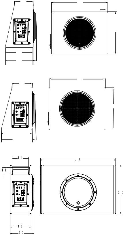
Overall |
13.3” x 18.0” x 8.9”/5.9” |
15.0” x 19.8” x 11.0”/7.0” |
11.38” x 17.6” x 4.84”/3.69” |
Dimensions |
(33.7cm x 45.7cm x |
(38.1cm x 50.3cm x |
(28.9cm x 44.8cm x |
(HxWxD) |
22.6/15cm) |
28/17.8cm) |
14.1/9.36cm) |
See illus.-1.1 for additional dimensions |
|
|
||
Model |
P300-10T |
P300-12T |
P500-12P |
|
Description |
10” Powered Subwoofer |
12” Powered Subwoofer |
12” Powered Subwoofer |
|
Power Rating |
300W / 600W |
300W / 600W |
|
500W / 1000W |
(RMS/Peak) |
|
|
|
|
Crossover Slope |
12dB/Oct |
12dB/Oct |
|
12dB/Oct |
Crossover Frequency |
Variable 50Hz-200Hz |
Variable 50Hz-200Hz |
Variable 50Hz-200Hz |
|
Punch Bass |
Variable 0 - +12dB @ 45Hz |
Variable 0 - +12dB @ 45Hz |
Variable 0 - +12dB @ 45Hz |
|
Frequency Response |
35Hz - 200Hz |
35Hz - 200Hz |
|
20Hz - 200Hz |
Input Sensitivity |
100mV - 3V |
100mV - 3V |
|
130mV - 5V |
Fuse Rating |
20A (2 X 10A) |
20A (2 X 10A) |
|
30A (2 X 15A) |
|
13.31” x 21.73” x |
14.96” x 25.83.” x |
|
12.88” x 24.76.” x |
Overall Dimensions |
11.0”/7.0” |
8.46”/4.8” |
|
”10.91/7.71” |
(HxWxD) |
(33.8cm x 55.2cm x |
(38cm x 65.6cm x |
(32.7cm x 62.9cm x |
|
|
20.1/12.2cm) |
21.5/12.2cm) |
|
27.7/189.2cm) |
|
See illus.-1.1 for additional dimensions |
|
|
|
CEA 2031 |
|
CEA 2006 |
|
|
Power handling on Rockford Fosgate speakers |
Power ratings on Rockford Fosgate amplifiers conform |
|||
conform to CEA-2031 industry standards. This means |
to CEA-2006 industry standards. These guidelines |
|||
your speaker has the capacity to handle power under |
mean your amplifier’s output power ratings are REAL |
|||
continuous demand, not instantaneous power handling, |
POWER numbers, not inflated marketing ratings. |
|||
that over time can damage voice coils. |
|
|
|
|
3
[5.98]
152.0
[8.82]
224.0
[9.85]
250
[7.08]
180
[10.94]  278
278 
[12.1] 307 
3.7
94
1.5
38
4.8
123
5.6
141
Specifications
[17.91]
455
[0.59]
15
|
|
P300-10 |
[13.31] |
||
338 |
|
|
[19.80]
|
|
|
|
380 |
P300-12 |
|
|
|
|
||||
|
|
|
[14.96] |
|||
|
|
|
|
|
|
|
|
|
|
|
|
|
|
17.6
448
|
|
|
|
P300-8P |
|
11.4 |
|
||
|
289 |
|
|
|
illus.-1.1
4

Specifications
4.8 |
21.7 |
|
552 |
||
122 |
||
|
||
338 |
P300-10T |
|
13.3 |
|
7.5 |
190 |
7.9 |
201 |
4.8 |
25.8 |
122 |
656 |
15.0 |
P300-12T |
380 |
|
8.5
215
P500-12P
5
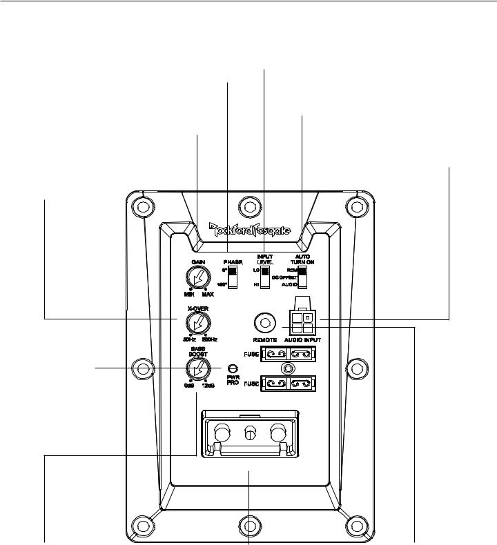
Design Features
Phase Switch
Allows you to select the output phase of the amplifier between 0° and 180°.
Gain Control
The input gain control is preset to match the output of most source units.
Variable Crossover
Is a built-in 12dB/octave Butterworth filter with a crossover point variable from 50Hz to 200Hz.
Power/Protect LED
Power LED illuminates blue when the unit is turned on. Protect LED illuminates red if a short circuit or to low of an impedance is detected at the speaker connections. The amplifier will automatically shut down if this occurs.
Input Level
Set the Input Level switch to match the outputs of your source unit.(LO - RCA or HI - Speaker Level)
Auto Turn On
Three different automatic turn-on modes can be selected; REM(+12V), DC Offset, and Audio.
Audio Input
The RCA/Speaker Harness utilizes either speaker level (high-level) or RCA (lowlevel) inputs.
Punch Bass
This is an adjustable Bass control adjustment variable from 0dB to +12dB @ 45Hz.
Power Connector
The power connector allows for quick connection and disconnection of the amplifier’s Remote, power and ground source. The power and ground are set-screw wire connectors and will accommodate 4 AWG. The remote is a set-screw wire connector and will accommodate 8 AWG.
Remote Punch Level
When connected, the “Gain Control” is linked and allows you to remotely control the output level of the amplifier from the dash or center console.
6 |
illus.-2.1 |
|
Installation
Contents
•Punch Powered Loaded Enclosure
•RCA/Speaker Harness
•Power Connector
•Remote Punch Level Control
•Installation & Operation Manual
•2X 10A Fuses Spare/2X 15A Fuses Spare (P500-12P only)
Installation Considerations
The following is a list of tools needed for installation:
•Fuse-holder and fuse. (See specifications for fuse rating)
•Volt/Ohm Meter
•Wire strippers
•Wire crimpers
•Wire cutters
•#2 Phillips screwdriver
•Battery post wrench
•Hand held drill w/assorted bits
•Assorted connectors
•Adequate Length—Red Power Wire
•Adequate Length—Remote Turn-on Wire
•Adequate Length—Black Grounding Wire
This section focuses on some of the vehicle considerations for installing your new powered loaded enclsoure. Preplanning your system layout and best wiring routes will save installation time. When deciding on the layout of your new system, be sure that each component will be easily accessible for making adjustments.
If you feel unsure about installing this system yourself, have it installed by a qualified technician.
Before installation, disconnect the battery negative (-) terminal to prevent damage to the unit, fire and/or possible
injury.
Before beginning any installation, follow these simple rules:
1.Be sure to carefully read and understand the instructions before attempting to install the unit.
2.For safety, disconnect the negative lead from the battery prior to beginning the installation.
3.For easier assembly, we suggest you run all wires prior to mounting your unit in place.
4.Route all of the RCA cables close together and away from any high current wires.
5.Use high quality connectors for a reliable installation and to minimize signal or power loss.
6.Think before you drill! Be careful not to cut or drill into gas tanks, fuel lines, brake or hydraulic lines, vacuum lines or electrical wiring when working on any vehicle.
7.Never run wires underneath the vehicle. Running the wires inside the vehicle provides the best protection.
8.Avoid running wires over or through sharp edges. Use rubber or plastic grommets to protect any wires routed through metal, especially the firewall.
9.ALWAYS protect the battery and electrical system from damage with proper fusing. Install the appropriate fuse holder and fuse on the +12V power wire within 18” (45.7 cm) of the battery terminal.
10. When grounding to the chassis of the vehicle, scrape all paint from the metal to ensure a good, clean ground connection. Grounding connections should be as short as possible and always be connected to metal that is welded to the main body, or chassis, of the vehicle. Seatbelt bolts should never be used for connecting to ground.
Mounting Locations
Trunk or Passenger Compartment Mounting
Choose a structurally sound location to mount your powered loaded enclosure. Mount the enclosure in such a manner that the amplifier has a minimum of 1” (2.54cm) of air gap around the amplifier’s heatsink to provide proper cooling to ensure optimum performance of the amplifier is strongly recommended.
Battery and Charging
Amplifiers will put an increased load on the vehicle’s battery and charging system. We recommend checking your alternator and battery condition to ensure that the electrical system has enough capacity to handle the increased load of your stereo system. Stock electrical systems which are in good condition should be able to handle the extra load of any Prime Series amplifier without problems, although battery and alternator life can be reduced slightly. To maximize the performance of your amplifier, we suggest the use of a heavy duty battery and an energy storage capacitor.
Wiring the System
If you do not feel comfortable with wiring your new unit, please see your local Authorized Rockford Fosgate Dealer for installation.
Before installation, disconnect the battery negative (-) terminal to prevent damage to the unit, fire and/or possible injury.
Avoid running power wires near the low level input cables, antenna, power leads, sensitive equipment or harnesses. The power wires carry substantial current and could induce noise into the audio system.
1.Plan the wire routing. Keep RCA cables close together but isolated from the amplifier’s power cables and any high power auto accessories, especially electric motors. This is done to prevent coupling the noise from radiated electrical fields into the audio signal. When feeding the wires through the firewall or any metal barrier, protect them with plastic or rubber grommets to prevent short circuits. Leave the wires long at this point to adjust for a precise fit at a later time.
7
 Loading...