


RFX9220M |
Installation & |
|
|
|
Operation |
|
Installation et fonctionnement |
|
Instalación y funcionamiento |
RFX Series
Source Units

INTRODUCTION
Dear Customer,
Congratulations on your purchase of the world’s finest brand of car audio source units. At Rockford Fosgate we are fanatics about musical reproduction at its best, and we are pleased you chose our product.Through years of engineering expertise, hand craftsmanship and critical testing procedures, we have created a wide range of products that reproduce music with all the clarity and richness you deserve.
For maximum performance we recommend you have your new Rockford Fosgate product installed by an Authorized Rockford Fosgate Dealer, as we provide specialized training through Rockford Technical Training Institute (RTTI). Please read your warranty and retain your receipt and original carton for possible future use.
Great product and competent installations are only a piece of the puzzle when it comes to your system. Make sure that your installer is using 100% authentic installation accessories from Connecting Punch in your installation. Connecting Punch has everything from RCA cables and speaker wire to power line and battery connectors. Insist on it! After all, your new system deserves nothing but the best.
To add the finishing touch to your new Rockford Fosgate image order your Rockford accessories, which include everything from T-shirts to jackets and hats.
To get a free brochure on Rockford Fosgate products and Rockford accessories, in the U.S. call 480-967-3565 or FAX 480-967-8132.
For all other countries, call +001-480-967-3565 or FAX +001-480-967-8132.
PRACTICE SAFE SOUND™
Continuous exposure to sound pressure levels over 100dB may cause permanent hearing loss. High powered auto sound systems may produce sound pressure levels well over 130dB. Use common sense and practice safe sound.
If, after reading your manual, you still have questions regarding this product, we recommend that you see your Rockford Fosgate dealer. If you need further assistance, you can call us direct at
1-800-669-9899. Be sure to have your serial number, model number and date of purchase available when you call.
The serial number can be found on the outside of the box. Please record it in the space provided below as your permanent record.This will serve as verification of your factory warranty and may become useful in recovering your source unit if it is ever stolen.
Serial Number: __________________________________________
Model Number: _________________________________________
TABLE OF CONTENTS
. . . . . . . . . . . . . . . . . . . . . . .Introduction |
. . 2 |
. . . . . . . . . . . . . . . . . .Operation-Basic |
10-13 |
Safety Instructions . . . . . . . . . . . . . . . . . |
. . 3 |
Initial Set-Up . . . . . . . . . . . . . . . . . . . . . . . . |
. . . 10 |
Precaution . . . . . . . . . . . . . . . . . . . . . . . . |
3-4 |
Reset Button . . . . . . . . . . . . . . . . . . . . . . . . |
. . . 10 |
Contents of Carton. . . . . . . . . . . . . . . . . . |
. 4 |
Power ON/OFF . . . . . . . . . . . . . . . . . . . . . |
. . . 10 |
Installation . . . . . . . . . . . . . . . . . . . . . . . . |
4-8 |
Clock Operation . . . . . . . . . . . . . . . . . . . . |
. . . 12 |
Remote (Battery Installation) . . . . . . . . . . . . . |
. 4 |
Mode Selection. . . . . . . . . . . . . . . . . . . . . . |
. . . 12 |
Installation Considerations. . . . . . . . . . . . . . . . |
. 5 |
Operation-Tuner . . . . . . . . . . . . . . . . . |
13-14 |
Mounting Locations . . . . . . . . . . . . . . . . . . . . . |
. 5 |
Operation-CD Player. . . . . . . . . . . . . . |
15-17 |
Standard Mount . . . . . . . . . . . . . . . . . . . . . . . . |
. 6 |
Operation-Wired Remote (Optional). |
. . 18 |
ISO-DIN Mount . . . . . . . . . . . . . . . . . . . . . . . . |
. 6 |
Operation-Title Programming. . . . . . . |
. . 19 |
Wiring the System . . . . . . . . . . . . . . . . . . . . . . |
. 7 |
Operation-MP3. . . . . . . . . . . . . . . . . . . |
20-21 |
Wiring Diagram . . . . . . . . . . . . . . . . . . . . . . . . |
. 8 |
Troubleshooting . . . . . . . . . . . . . . . . . . |
22-25 |
Source Unit Features. . . . . . . . . . . . . . . . |
8-9 |
Specifications . . . . . . . . . . . . . . . . . . . . . |
. . 26 |
|
|
Warranty Information . . . . . . . . . . . . . |
. . 27 |
NOTE: Review each section for more detailed information.
2
GETTING STARTED
Welcome to Rockford Fosgate! This manual is designed to provide information for the owner, salesperson and installer. For those of you who want quick information on how to install this product, please turn to the Installation Section of this manual. Other information can be located by using the Table of Contents. We, at Rockford Fosgate, have worked very hard to make sure all the information in this manual is current. But, as we are constantly finding new ways to improve our product, this information is subject to change without notice.
NOTE:This manual uses abbreviations for the following terms:
TUNER = AM/FM Radio Tuner
CDP = In-Dash CD Player
CDX = CD Changer
AUX = External Auxiliary Input
MP3 = Computer Generated Audio File Format
SAFETY INSTRUCTIONS
This symbol with “WARNING” is intended to alert the user to the presence of important instructions. Failure to heed the instructions will result in severe injury or death.
This symbol with “CAUTION” is intended to alert the user to the presence of important instructions. Failure to heed the instructions can result in injury or unit damage.
CAUTION:To prevent injury and damage to the unit, please read and follow the instructions in this manual. We want you to have enjoyment from this system, not a headache.
CAUTION If you feel unsure about installing this system yourself, have it installed by a qualified Rockford Fosgate technician.
CAUTION Before installation, disconnect the battery negative (-) terminal to prevent damage to the unit, fire and/or possible injury.
PRECAUTIONS
SOURCE UNIT AND OPTIONAL CD CHANGER
+65°C
–10°C
Operating Temperature
Be sure the temperature inside the vehicle is between –10° C and +65° C (+14°F and +149°F). DO NOT play a disc if the temperature is higher or lower than the operating range.
Moisture Condensation
The CD playback may waver due to condensation. If this occurs, remove the disc from the source unit and wait approximately an hour for the moisture to evaporate.
Environment Exposure
DO NOT expose the Source Unit or optional CD Changer to any of the following: direct sun and heat, high humidity, excessive dust, excessive vibration and rain or water.
Visit our web site for the latest information on all Rockford products.
www.rockfordfosgate.com
3
PRECAUTIONS
Handling the Detachable Faceplate
DO NOT drop or cause shock to the faceplate as serious damage may occur. Protect the faceplate by storing it in the supplied carrying case.
Avoid Mechanical Malfunction


 DO NOT grab a disc while it is being automatically loaded into the source unit. Doing this may cause serious damage to the playback mechanism and/or damage to the disc.
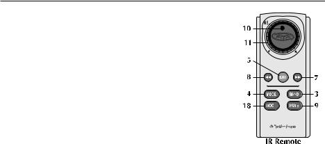
IR REMOTE CONTROLLER
Environment Exposure
DO NOT expose the IR Remote to any of the following: direct sun and heat, high humidity and rain or water.
Handling the IR Remote
DO NOT drop or cause shock to the IR Remote as serious damage may occur.
COMPACT DISCS
|
|
o |
un |
d |
s |
|
|
|
so |
|
|
s |
|
|
o |
|
|
i |
||
|
civ |
|
f
•
e h t
lg
jun
nuj
gle
ht e
•
v |
|
ici |
|
o |
|
|
s |
|
so |
s d |
nu |
|
|
f o |
|
Disc Handling and Care
DO NOT touch the playing side (opposite of label side) of the disc. When handling the disc, only the outer edges or center hole of the disc should be touched. DO NOT affix any sticker or label to the disc. DO NOT apply vinyl record spray, anti-static agent, acetone, or any other volatile chemicals to the disc.
|
|
o |
un |
d |
s |
|
|
|
so |
|
|
s |
|
|
o |
|
|
i |
||
|
civ |
|
f
•
e h t
lg
j
nu
un
j
gle
t eh
•
v |
|
ici |
|
o |
|
|
s |
|
so |
s d |
nu |
|
|
f o |
|
Damaged Disc
DO NOT play a cracked, warped, or damaged disc. Doing this may cause serious damage to the playback mechanism.
|
|
o |
un |
d |
s |
|
|
|
so |
|
|
s |
|
|
o |
|
|
i |
||
|
civ |
|
f
•
L |
|
|
ngle |
IQ ju |
|
||
eU |
|
|
|
th |
ID |
|
|
|
|
S |
|
|
|
W |
|
|
|
O |
|
|
|
|
RD |
|
|
|
IN |
|
|
|
Ct |
|
|
|
eh |
elgn |
uj |
||
|
|
||
•
v |
|
ici |
|
o |
|
|
s |
|
so |
s d |
nu |
|
|
f o |
|
New Discs
The CD player will eject discs that have either been inserted incorrectly or have irregular surfaces. If a new disc is ejected after loading, feel around the outer edge of the CD and its center hole. Any small burrs or irregularities could inhibit proper loading of the disc.To remove the burrs, rub the inside edge of the hole and outside edge of the disc with an object such as a ball point pen.
CONTENTS OF CARTON
Model 9220 Source unit |
Hardware Package |
Installation & Operation Manual |
16-pin Power Harness |
Standard Mounting Sleeve |
Faceplate Cases (1 Soft and 1 Hard) |
Back strap (taped to box insert) |
IR Remote Control (Small Box Inside Carton) |
Chassis Release Keys (2) |
|
|
|
INSTALLATION
REMOTE
Battery Installation
1.Remove the battery cover on the back of the remote.
2Install two (2) AAA batteries with the polarities correct as show by the diagram inside the battery compartment of the remote.
4

|
INSTALLATION |
INSTALLATION CONSIDERATIONS |
|
The following is a list of tools needed for installation: |
|
Volt/Ohm Meter |
Hand held drill w/assorted bits |
Wire strippers |
1/8" diameter heatshrink tubing |
Wire crimpers |
Assorted connectors |
Wire cutters |
Soldering iron |
#2 Phillips screwdriver |
Solder |
Battery post wrench |
Heat gun |
This section focuses on some of the vehicle considerations for installing your new Source Unit. Pre-planning your system layout and best wiring routes will save installation time. When deciding on the layout of your new system, be sure that each component will be easily accessible for making adjustments.
CAUTION:If you feel unsure about installing this system yourself, have it installed by a qualified technician.
CAUTION:Before installation, disconnect the battery negative (-) terminal to prevent damage to the unit, fire and/or possible injury.
Before beginning any installation, follow these simple rules:
1.Be sure to carefully read and understand the instructions before attempting to install the Unit.
2.For safety, disconnect the negative lead from the battery prior to beginning the installation.
3.For easier assembly, we suggest you run all wires prior to mounting your Source Unit in place.
4.Route all of the RCA cables close together and away from any high current wires.
5.Use high quality connectors for a reliable installation and to minimize signal or power loss.
6.Think before you drill! Be careful not to cut or drill into gas tanks, fuel lines, brake or hydraulic lines, vacuum lines or electrical wiring when working on any vehicle.
7.Never run wires underneath the vehicle. Running the wires inside the vehicle provides the best protection.
8.Avoid running wires over or through sharp edges. Use rubber or plastic grommets to protect any wires routed through metal, especially the firewall.
9.ALWAYS protect the battery and electrical system from damage with proper fusing. Install the appropriate fuse holder and fuse on the +12V power wire within 18” (45.7 cm) of the battery terminal.
10.When grounding to the chassis of the vehicle, scrape all paint from the metal to ensure a good, clean ground connection. Grounding connections should be as short as possible and always be connected to metal that is welded to the main body, or chassis, of the vehicle.
MOUNTING LOCATIONS
The mounting position of your source unit will have a great effect on the performance of your in-dash CD Player.The source unit can be installed in a wide range of operating locations. However, care should be taken to ensure optimum performance.
Engine Compartment
Never mount this unit in the engine compartment. Mounting the unit in the engine compartment will void your warranty.
Instrument Panel
Mounting the source unit in the instrument panel provides optimum access.The source unit should be securely mounted using the “Standard Mount” or “ISO-DIN Mount” method to ensure optimum CD Player performance.
5
INSTALLATION
Center Console
Mounting the source unit in the center console provides optimum access. Be sure the installation does not interfere with the operation of the gear shift or parking brake.
Glove Box
Mounting the source unit in the glove box is adequate, but does not provide easy access. Glove box mounting should only be done if “Instrument Panel” or ”Center Console,” mounting is not acceptable (i.e., maintaining integrity of older vehicles with metal dashboards.)
Under Dash
Mounting the source unit under the dash is adequate, but does not provide easy access. Under dash mounting should only be done if “Instrument Panel,” ”Center Console” or ”Glove Box” mounting is not acceptable. Mount the source unit off to the side of the driver's area to reduce interference with the parking brake, gear shift, or operating pedals.
NOTE:The source unit should have a mounting angle within ±20° from horizontal.
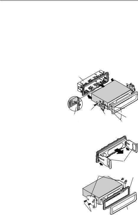
STANDARD MOUNT
Installing;
•Mount the Locks for the Installation Sleeve onto the source unit (use supplied screws).
•Mount the Installation Sleeve into a secure instrument panel.
NOTE: Make sure to mount the Source Unit as close to horizontal as possible for optimum CD Player performance. Mounting Angles of up to ±20˚ from horizontal can be accommodated.
•Bend Appropriate Tabs on all sides of the installation sleeve. See Installation Sheet.
Sleeve
Screw
Back Strap


 Dash
Dash
|
|
+ |
|
|
Trim |
|
|
2 |
|
|
|
o |
|
0 |
|
||
|
|
ϒ |
|
||
H |
ri |
|
|
|
|
|
|
z |
|
|
|
|
|
o |
|
|
|
Lock |
|
|
nt |
|
|
|
- |
|
al |
|
|
|
|
|
|
||
|
|
|
|
|
|
|
|
2 |
|
|
|
|
|
0 |
|
|
|
|
|
|
ϒ |
|
|
•Install Source Unit by sliding unit into installation sleeve until it clicks into place.
•Mount Back Strap securely behind the instrument panel to prevent source unit vibration.
•Back strap Screw should be 6mm max (use supplied screw).
•Connect Antenna to antenna jack on rear of source unit.
Removal;
• Disconnect Back Strap from rear of radio (if used).
• Remove Trim Piece from front of radio.
• Insert Release Keys into left and right sides of source unit to disengage locks.
•Remove Source Unit from installation sleeve with release
keys.
Release Key
Dash
ISO-DIN MOUNT
Installing;
• RemoveTrim Piece and Installation Sleeve from source unit. |
|
|
|
• Factory Bracket should align with two mounting holes on each |
|
|
|
side of source unit. |
|
|
|
• ISOScrews should be 6mm max (use supplied screws). |
|
|
|
• Connect Antenna to antenna jack on rear of source unit. |
|
Trim |
|
• Install Source Unit into instrument panel. |
Screw |
||
|
6
INSTALLATION
WIRING THE SYSTEM
NOTE: See diagram on following page to help you connect your system.
CAUTION: If you do not feel comfortable with wiring your new source unit, please see your local Authorized Rockford Fosgate Dealer for installation.
CAUTION: Before installation, disconnect the battery negative (-) terminal to prevent damage to the unit, fire and/or possible injury.
1.Install the 16-Pin Power Harness by connecting the corresponding wires to the electrical and audio system. Solder and heat shrink all connections for a reliable installation. For each connection, cut a 1" piece of heat shrink tubing and slide over one of the wires. Strip each wire 3/8" then twist together and solder. Slide the tubing over the connection and shrink the tubing with a hot air gun until no bare wire is exposed.
2.Connect the BLACK (Ground) wire to chassis ground. Prepare the chassis ground by scraping any paint from the metal surface and thoroughly clean the area of all dirt and grease. Strip the end of the wire and attach a ring connector. Fasten the wire to the chassis using a non-anodized screw and star washer.
3.Connect the YELLOW (Backup) wire to a source of constant +12V (for retaining memory on userprogrammed functions).The source should always have +12V, even when the ignition is off and the car is not running.
4.Connect the RED (ACC +B) wire (Ignition) to a source of switched +12V (is on only when ignition key is in “accessory” or “run” position). Connect the RED wire to a switched +12 volt positive source.The switched signal is usually taken from the ACC (accessory) position of the ignition. If the vehicle does not have an ACC position, connect the wire to the switched ON position of the ignition.
5.Connect the ORANGE (Dimmer) wire to the lighting switch terminal.This will dim the main display by 30% when the headlights are turned on.
6.Connect the LT. BLUE (Remote B+) wire to the “Remote Turn-On” leads of the amplifier(s).This will turn-on the external amplifiers when the source unit is powered on.
7.Connect the BLUE/RED (Auto Ant.) wire to the “Power Antenna” lead.This will raise a fully automatic
antenna when the source unit is powered on, but only in Tuner Mode.
8.Connect the PINK (Telephone Mute) wire for cell phone mute to the wire on the cell phone harness that provides ground when the phone rings.
9a. Connecting Speakers (Not using external amplifier)
Connect the Speaker Wires to the corresponding speaker leads by soldering and heat shrinking all connections for a reliable installation. If only one pair of speakers is utilized in the system, use only the FRONT speaker leads and heat shrink the unused REAR leads to prevent from shorting out. Be sure to maintain speaker polarity. DO NOT chassis ground any speaker leads as unstable operation may result.
9b. Connecting Speakers (Using external amplifier)
Install the Preamp Output Harness by plugging the RCA cables into the corresponding extension RCAs that feed the input of the amplifiers. Be sure to route the signal cables away from any high current wires to prevent coupling noise from radiated electrical fields into the audio signal.The FRONT OUTPUT connects to the Front speaker's amplifier.The REAR OUTPUT connects to the Rear speaker's amplifier.The SUM OUTPUT connects to the Subwoofer amplifier.
10.Connect the AUX INPUT to the external audio source (this inserts the audio before the volume control on the source unit).The input voltage this circuit can accept is 1–3V RMS.
11.Connect the CD Changer (optional) by plugging the 8-pin DIN cable into the connector located at the rear of the source unit. DO NOT connect the optional Wired Remote into this connector.
12.Connect the Wired Remote (optional) by plugging the 8-pin DIN controller cable into the pigtail connector hanging from the rear of the source unit. DO NOT connect the optional CD Changer into this connector.
13.Connect the Antenna by plugging the antenna cable into the connector located at the rear of the source unit. Be sure the antenna is securely grounded to the vehicle for proper radio reception.
7

INSTALLATION
DO NOT connect optional CD Changer to
DO NOT connect optional Wired Remote to this port.
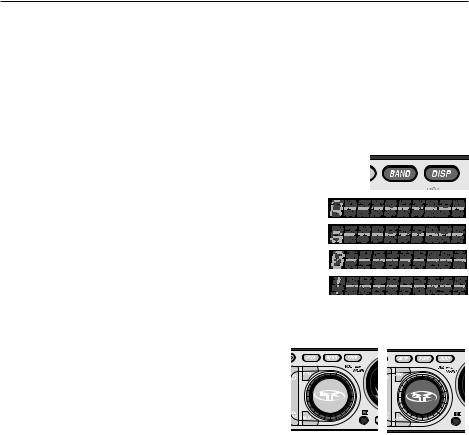
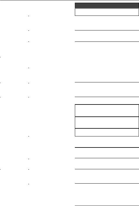
SOURCE UNIT FEATURES
8
SOURCE UNIT FEATURES
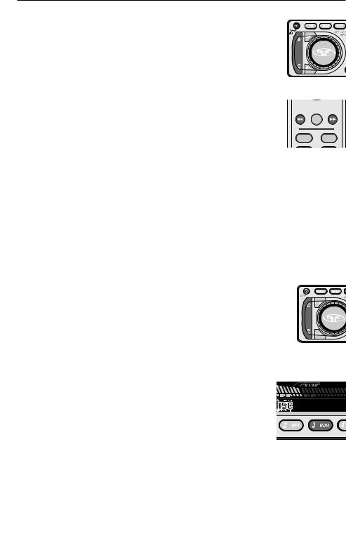
1.OFF – Turns the source unit on and off.
2. DISP – Toggles between different display features in main display; when pressed and held for 1 second, toggles clock between hours and minutes.
3. BAND – Selects which bank of tuner presets (FM1/FM2/AM) should be active.
4. MODE – Selects between TUNER/CDP/CDX/AUX1 modes.
5. ENTER – Enables tracks in MP3 mode.
6. OPEN/EJ – Opens the faceplate and ejects CDs from the in-dash CD player.
7. UP (  ) – Selects the next radio station in TUNER mode and selects the next track in CDP/CDX mode.
8. DN {DOWN} ( ) – Selects the previous radio station in TUNER mode and selects the previous track in CDP/CDX mode.
9.MUTE – Mutes audio in TUNER and AUX1 modes. Pauses the disc in CDP/CDX mode.
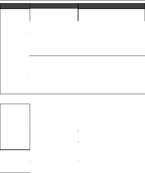
10.SELECT (Volume Center) – When pressed, selects between SUM, BASS,TREBLE, BALANCE, FADER, and VOLUME modes. Press and hold to enter set-up menu (see Setup Options). Press to enter character when using the Programmable Title option.
11.VOLUME (Outside) – Used to control volume level. Adjusts default levels during set-up options. Selects characters when using the Programmable Title option.
12.R – Infrared eye for remote operation.
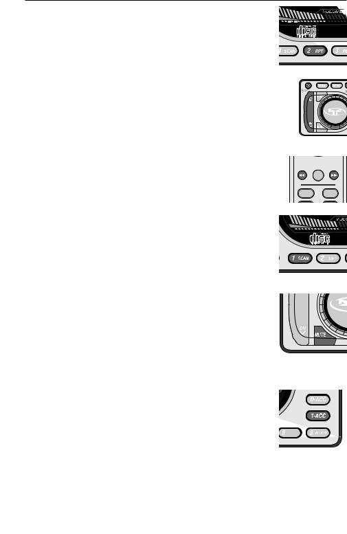
13.PRESET 1/SCAN – Selects radio preset #1 in TUNER mode and scans each track on the disc in CDP/CDX mode.
14.PRESET 2/RPT – Selects radio preset #2 in TUNER mode and repeats the current track in CDP/CDX mode.
15.PRESET 3/RDM – Selects radio preset #3 in TUNER mode and selects tracks at random in CDP/CDX mode.
16.PRESET 4/DOWN – Selects radio preset #4 in TUNER mode, or previous disk in CDX Mode.
17.PRESET 5/UP – Selects radio preset #5 in TUNER mode, or next disk in CDX Mode.
18.PRESET 0/ROOT – Selects radio preset #0 in TUNER mode and returns unit to root directory in MP3 mode.
19.T-ACC – Allows you to enter the track number you want manually .
20.D-ACC – Allows you to enter the disc number you want,CDX mode (available only for 6 disc player).
21.AS – Press to store strongest radio stations in each tuner bank in AUTO STORE mode.
22 PUNCH – Enables bass and treble response to be boosted at all volume levels.
IMPORTANT:The 8-Pin communication BUS on the back of the unit is used ONLY for the optional CD changers, RFX8810 or RFX8620M, and is not backwards compatible with older RFX models. Rockford Fosgate recommends connecting only the appropriate RFX models together. Rockford Fosgate does not assume responsibility when using other manufacturers’ source units with Rockford Fosgate CD changers (or vice versa). DO NOT connect the optional wired remote into this BUS. Connect the wired remote ONLY into the 8-Pin connector on the pigtail.
9
OPERATION – BASIC
INITIAL SETUP
NOTE: Items shown in () refer to remote control functions.
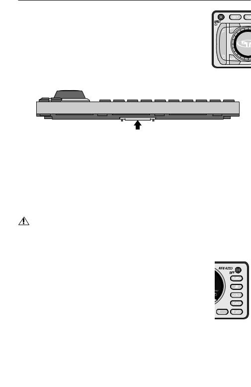
DETACHABLE FACEPLATE
The faceplate is detachable as a theft deterrent.
To Detach the Faceplate:
1. Press the Open Button to cause the faceplate to slide down and forward.
2.Press the release button on the bottom front edge of the faceplate and slide the faceplate away from the unit.
3.The faceplate bracket will automatically close after 5 seconds.
Push
To Attach the Faceplate
1.Make sure that the faceplate bracket is in the closed position.
2.Press the faceplate against the front of the unit until it clicks into place.
 CAUTION:Do not attempt to attach the faceplate to the faceplate bracket when the bracket is in the open position.You may cause damage to the mechanism that may void your warranty
3.If desired, the faceplate can be permanently attached by affixing it to the bracket with the screw provided.
RESET BUTTON
CAUTION: Do not press the Reset Button too hard or you may cause damage that may void your warranty. If you need assistance, please consult an Authorized Rockford Fosgate Dealer.
1.Follow the instructions above to detach the faceplate.
2.Insert a paper clip or other slender object into the Reset Button hole in the lower left corner of the unit and gently press it in until the button clicks.
POWER ON/OFF
1. Press the OFF button to turn the radio on.
2. Press the OFF button again to turn the radio off.
Any Button Wake-Up
Press any button, except OPEN or DISP to “wake-up” the radio from sleep mode.
NOTE: When the radio is off, “sleep mode”, the clock will be displayed.
10
OPERATION – BASIC
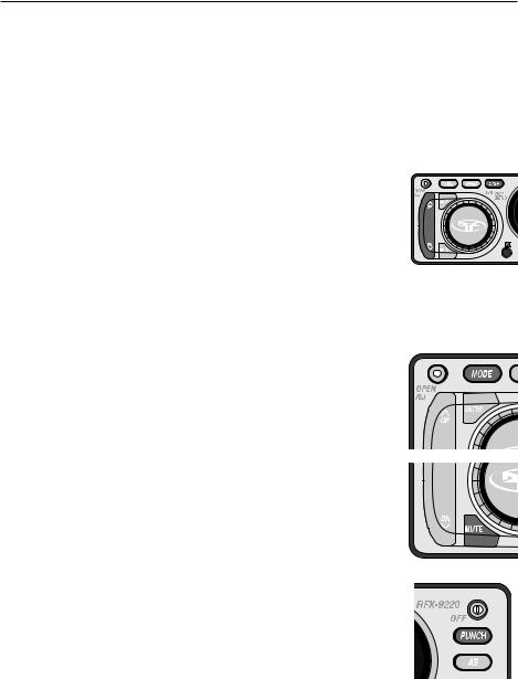
VOLUME KNOB/TONE CONTROLS
The Volume knob is a multifunction controller and handles the Volume,Tone Controls, and Setup Options, see below.
To Control Volume
1.Turn the VOLUME knob (Volume Outside) clockwise to raise volume.
2.Turn the VOLUME knob (Volume Outside) counter-clockwise to lower volume.
To Adjust Tone Controls
1.Press the SELECT button (Volume Center) repeatedly to cycle through SUM > BASS > TREBLE > BALANCE > FADER > VOLUME.
2.Turn the VOLUME knob (Volume Outside) to increase, clockwise, or decrease, counter-clockwise, the selected function.
Source Tone Memory
Turn Outside |
Remote |
|
Press Center
Individual Bass & Treble settings are memorized for TUNER / CD PLAYER / CD CHANGER / AUX1.
NOTE: If no adjustment is made after 5 seconds, the MENU knob will revert to VOLUME mode.
SETUP OPTIONS
The list below shows the default Setup Options.The bracketed items are the alternate options contained within each Setup Option.
Selecting Options
1. Press and hold the SELECT button (Volume Center) for about 1 second until the first Option appears {LOCAL}.
2. |
Press the SELECT button (Volume Center) repeatedly to cycle through all |
Press & Hold Center |
||
|
Setup Options.The first three options only affect the Tuner Mode. |
|||
|
|
|||
3. |
To change an Option, press the UP or DN {Down} Button |
Remote |
||
|
( |
or |
). |
|
4. To store, wait 5 seconds and the Display will return to the last Mode shown.
• LOCAL [DX] — Adjusts the sensitivity of the tuner for rural conditions where there are weak radio stations while Local adjusts the sensitivity for city conditions where there are several strong radio stations.
•AMERICAS [EUR/AUST] — Allows tuning of frequencies available in different parts of the world.
• P. PLAY [EJ MUTE] — Plays the Tuner after you eject a CD while Eject Mute |
ENT |
mutes the Tuner after you eject a CD. |
|
•V/BAR ON [V/BAR OFF] — Displays the Volume Bar at the bottom of the Front Panel while Volume Bar Off turns it off.
•INI VOL 15 — Sets the maximum Initial Volume when the unit turns on. Initial Volume sets point of maximum volume when the unit is turned on. If the volume setting was lower than the initial volume setting when the unit is turned off, then the lower volume will be used at turn on. If the volume setting was higher than the initial volume setting, then the initial volume setting is used at turn on.This feature prevents accidental high volume turn on as well as allows high volume settings to be retained in case another preamplifier is the system’s main volume control.
• CONTRAST [VIEW 6] — Controls the view angle of the display. Allows adjustment for best visibility.
•SUM FLAT [80HZ] — Means third pair of RCA pre-outs is full-range while 80Hz means that the preouts are crossed-over 80Hz low-pass for subwoofer use.
11
OPERATION – BASIC
• SCROLL ON [SCROLL OFF] — Titles scroll across panel screen. Scroll Off prevents scrolling.
•AUX1 IN 0 [+6, –6] — Allows you to boost the input volume of a weak external audio source or diminish a powerful one. Useful for external sources: MP3 players, video games,VCPs, etc.
• VDSEL ON [VDSEL OFF] — This is for the low voltage detction. While "ON", if the power voltage to the unit drops below approximately 10 volts, the unit will begin "beeping".Turning this "OFF" will bypass the low voltage detection.
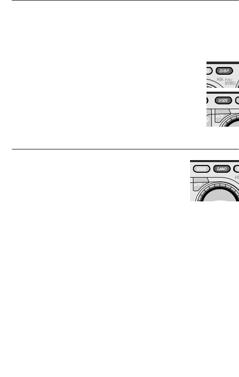
CLOCK OPERATION
Setting the Clock Hours
1. Press and hold the DISP button for 1 second until the hour flashes.
2. Press UP or DN {Down} button to set the hour.
Setting the Clock Minutes
1. Press and the DISP button a second time and the minutes will flash.
2. Press UP or DN {Down} button to set the minutes.
Your settings will be saved after the clock has flashed for 5 seconds.
NOTE: When the radio is off (sleep mode) the clock will be displayed.
MODE SELECTION
Press the MODE button repeatedly to cycle through the following modes:
•CDP PLAY — Enables CD Player if a CD is inserted.
• AUX1 — Allows for an external audio source to attach to the sound system.
• TUNER — Enables the Tuner.
MUTE
1. Press the MUTE button to dampen the volume.
2. Press the MUTE button a second time to revert the audio to the previous level.
NOTE: The panel will display MUTE until the function is canceled.
PUNCH
The Punch button enables the bass and treble response of the audio output to be boosted for all listening levels.
1.Press the PUNCH button to enable the Punch feature.
2.Press the PUNCH button again to disable.
NOTE: The panel will display "Punch" when the Punch feature is on.
PANEL DISPLAY
Tuner Mode:
The panel will display the band, FM1, FM2 or AM1, and the station frequency, unless the default has been changed to TITLE DEFAULT and a station title has been programmed in.
12
OPERATION – BASIC
CD or CDX Modes
While playing a disc the panel will display the track number and the time played, also the disc number if in CDX mode, unless the default has been changed to TITLE DEFAULT and a disc title has been programmed in.
All Other Modes
The panel will display the mode AUX1, unless the default has been changed to TITLE DEFAULT and a title has been programmed in.
PANEL DISPLAY DEFAULT
To set the default, press and hold the DISP button until the hours on the clock begin blinking. Immediately pressing MODE button allows selection of the default Display by toggling between Tuner frequency, or track time in CD Mode, and station or disc name, if titled. See PROGRAMMING TITLES for information.
NOTE: A maximum total of 100 titles can be programmed into the unit.
OPERATION –TUNER
SELECTING A BAND
Press the BAND button repeatedly to cycle through FM1, FM2, and AM.The act of selecting the band automatically enables that band.
TUNER OPTIONS
LOCAL and AMERICAS are the default Tuner Options settings.The bracketed options are alternate options.
•LOCAL [DX]
•AMERICAS [EUR/AUST]
•P. PLAY [EJ MUTE]
Selecting Tuner Options
See SETUP OPTIONS to change tuner options.
SELECTING A STATION
Press the UP or DN {Down} Button ( or
or  ) once and the Tuner will rapidly proceed to the next (UP) or pervious (DOWN) station.
Press and holding either the UP or DN {Down} Button ( or
or  ) for 1 second will put you into TUNER MANUAL mode.You can now manually search up or down at a rate of one digit per click (pressing and holding the UP or DN {Down} Button (
 or
or  ) will allow rapid searching).
PRESET BUTTONS
Each Tuner mode—FM1, FM2, and AM—has 10 presets for a total of 30 presets.
To Set a Preset Button
1.Tune the Tuner to the station you wish to program.
2.Press and hold any preset button (1 to 0) for five seconds and it will program that setting.
13

OPERATION –TUNER
AUTO STORE
If you want the Tuner to select the 10 most powerful stations in order of their signal strength and assign them to Preset buttons 1 to 0, you can use Auto Store.
1. Press and the AS button and the Tuner will scan the entire dial.
2. Auto Store will store radio stations independently in the selected tuner bank
(FM1/FM2/AM).
PROGRAMMING STATION TITLES
The name of a Station can be stored in memory using up to 10 characters as a title.
See PROGRAMMING TITLES at the end of the OPERATION-CD PLAYER section.
Available on International R.D.S. Models Only
AF/TP MODE
TP (Traffic Program) Mode will automatically switch to receive a Traffic Announcement regardless of the current operating mode of the unit. EON TA are stations that do not have a TRAFFIC PROGRAM but can provide information on other radio stations that do.
AF (Alternative Frequencies) Mode compares the signal level of the current station with the signal level of other alternative frequencies on the same radio network (see PTY Mode). If the AF provides a stronger signal than the current frequency, the radio will switch to the stronger AF.
Traffic Program Mode (TP)
1.Press the AF/TP button to engage TP Mode, and again to disengage TP Mode.
2.When TP is blinking,TP Mode is on and there is no TP DATA to receive.
3.The SEEK or AS function will stop only at radio stations providing TP or EON TA.
Alternative Frequencies Mode (AF)
1.Press and hold the AF/TP button for 1 second to engage AF Mode.
2.Press and hold AF/TP again for 1 second to disengage AF Mode.
PTY MODE
PTY (Program Type) can search for radio stations via MUSIC MODE or SPEECH MODE networks. Music Mode categorizes radio stations into Pop, Rock, Modern Music, Light, Classics, and others. Speech Mode categorizes music into News, Affairs, Info, Sports, Education, Drama, Culture, and Science. REG (Region Mode) will switch the station to another that has the same PI CODE (station that provides exactly the same program) but in a different REGION.
Program Type Mode
1.Press the PTY button to cycle through MUSIC, SPEECH, and PTY OFF.
2.Press the PRESET button that corresponds to the mode type (refer to chart).
Region Mode
1.Press and hold the PTY button for 1 second to turn on Region Mode.
2.Press and hold the PTY button again for 1 second to turn off Region Mode.
NOTE: The LCD will display “REG” when AF and REG modes are on.
KEY |
Music Mode |
Speech Mode |
M1 |
POP M |
NEWS |
M2 |
ROCK M |
AFFAIRS |
M3 |
M.O.R.M. |
INFO |
M4 |
LIGHT M |
SPORT |
M5 |
CLASSICS |
EDUCATE |
M6 |
OTHER M |
DRAMA |
M7 |
– |
CULTURE |
M8 |
– |
SCIENCE |
M9 |
– |
VARIED |
14
OPERATION – CD PLAYER
Basic Operation
NOTE: This system will play AUDIO CDs created on a Macintosh
NOTE: This system will play CD-R and CD-RW discs.
To Play a CD
1.Press OPEN button and the Front Panel will slide open.
2.Insert a CD and the Front Panel will slide closed after 5 seconds.
3.CDP PLAY will auto-select and the CD will begin playing track 1 immediately.
4.Use UP or DN {Down} Button ( or
or  )to change tracks.
To Eject a Disc
1.Press the OPEN button, "EJECT" appears on the display and the Front Panel will slide open and eject the disc.
2.Press the OPEN button while Front Panel is open, or wait 5 seconds and the Front Panel will auto-close.
Remote
ENT
MODE BAND
NOTE: If OPEN is pressed and held for longer than 1 second, the Front Panel will open and Eject will not be engaged. If the disc is not romoved after being ejected, the unit will wait 10 seconds before pulling the disc back in and auto-closing the front panel. It will not start playing the disc if this happens.
Panel Display
While playing a disc the panel will display the track number and the time played, also the disc number if in CDX mode, unless the default has been change to TITLE DEFAULT and a disc title has been programmed in. See PANEL DISPLAY DEFAULT in OPERATION-BASIC.
Advanced Operation
The following also works with the optional CDX Multi-Disc Changer if it has been installed. NOTE: Items shown in () refer to remote control functions.
Track Selection
1. Press the UP Button ( ) to select the next track on the disc.
2. Press the DN {Down} Button ( ) to select the previous track.
Considerations
CDP MODE:The disc will start over at track 1 again after the last track plays.
CDX MODE: When the last track number on the current disc is reached, the next disc will load in the CD changer and begin playing track 1.
To Play Tracks at Random
1. Press the 3/RDM button to randomize the tracks on a disk. If you have a multi-disc changer, press and hold the 3/RDM button for 1 second to randomize the discs and tracks.
2. To cancel, press the 3/RDM button a second time.
NOTE:The panel will display RDM until the function is cancelled.
15
OPERATION – CD PLAYER
To Repeat a Track
1. Press the 2/RPT button to to repeat the track currently playing..
2. To cancel, press the 2/RPT button a second time. Pressing the 1/SCAN or 3/RDM button will also cancel repeat, or pressing and holding the UP or DN {Down} Button ( or
or  ).
).
NOTE: The panel will display RPT until the function is cancelled.
Forward/Reverse
Press the DN {Down} Button ( ) and the player will take you to the start of the same track as long as that track is more than 10 seconds in. If the track is less than 10 seconds in, pressing the DN {Down} Button (
 ) will take the player to the beginning of the previous track. Pressing the UP Button (
 ) takes you to the next track.
Fast Forward/Reverse
1.Press and hold the UP Button ( ) to fast forward the track.
2.Press and hold the DN {Down} Button ( ) to fast rewind the track.
NOTE: The panel will display the elapsed time as long as the UP or DN {Down} Button ( or
or  ) is pressed.
Track Scan
Track Scan plays the intro to each track for 10 seconds before moving to the next track on the currently playing disc.
1.Press the 1/SCAN button to begin track scan mode.
2.To cancel, press the 1/SCAN (button a second time.
NOTE: The panel will display 1/SCAN, the CD track number and elapsed time for 10 seconds for each track until the function is cancelled.
Remote
ENT
MODE BAND
Pause CD
1.Press the MUTE button to pause the CD.
2.Press the MUTE button a second time to resume playing the disc.
NOTE: The panel will display PAUSE and the track number until the function is canceled.
Direct Track Access
Direct Track Access allows any track to be immediately selected and played.This method is faster than manually cycling through each track on the disc.
1.Press the T-ACC button to select Direct Track Access mode.
2.Press the number, 1-2-3-4-5-6-7-8-9-0, to access the desired track on the disc.
EXAMPLE: Pressing the T-ACC button, then 01 takes you to track 1, pressing 12 takes you to track 12 and so forth. Pressing just 1 digit, 7, will take you to track 7 after 5 seconds.
16
OPERATION – CD PLAYER
RFX 8620M CD Changer Operation (Optional Accessory)
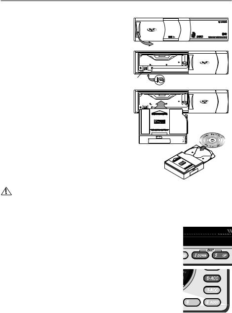
Magazine Eject
1.Slide door open in the direction shown.
2.Press the EJECT button to release the disc magazine from the CD changer.
NOTE: The panel will display NO CD, if in CDX mode, then go to AUX1 mode.
NOTE: If the front eject button does not work, a manual eject lever is visible through a hole at the bottom of the unit. Move the lever in the direction shown to eject magazine.
Loading Disc to the Magazine
1.Pull out the desired disc tray number from the magazine.
2.Place the disc into the magazine, label side up.
3.Push the disc tray back into the magazine.
NOTE: Discs numbers are arranged from the bottom up.
Slide Door
Eject |
Manual Eject |
|
Label |
|
Side Up |
Loading the Magazine to the CD Changer
The INSERT IN THIS DIRECTION arrow indicates the proper direction that the magazine should be loaded into the CD changer.
6  5
5  4
4  3
3  2
2  1
1
PUSH
CAUTION: Avoid installing or leaving the
magazine where it would be subject to high temperatures such as from direct sunlight or from hot air from the heater. Doing so will damage the unit.
CD Changer Mode
1.Press the MODE button until CDX PLAY is displayed.
2.The CD changer will immediately begin playing track #1 of the first available disc.
3.If the changer was previously initialized, the changer will resume playing the last 


 track initialized.
Disc Selection
1. Press the PRESET 5–UP button to select the next disc in the magazine.
2. Press the PRESET 4–DOWN button to select the previous disc in the magazine.
3. Press the D-ACC button and numbers 1-8 for direct disc access.
Panel Display
While playing a disc the panel will display the track number and the time played, also the disc number, unless the default has been change to TITLE DEFAULT and a disc title has been programmed in. See PANEL DISPLAY DEFAULT in
OPERATION-BASIC.
NOTE: When the last track # on the current disc is reached, the next disc will load and begin playing track #1.
17
OPERATION – WIRED REMOTE (OPTIONAL)
RFX MR1 Wired Remote Control (Optional Accessory)
CAUTION:To prevent injury and/or damage to the unit and/or vehicle, read and follow all safety precautions.
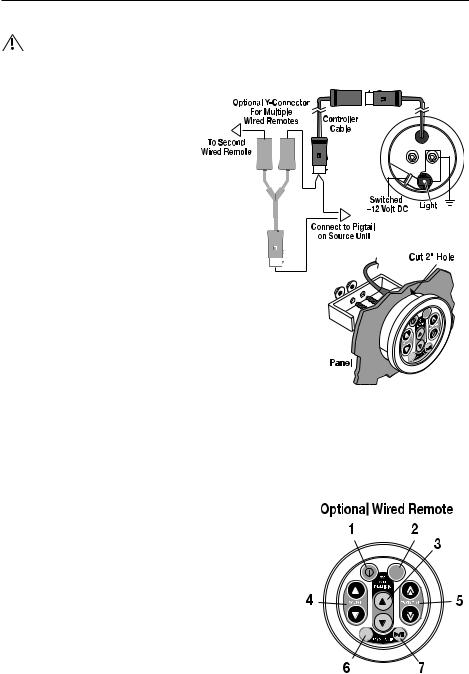
Installation
1.cut a 2" hole into the panel where the
controller will be mounted.
Light Connection
2. Connect a wire from a source of switched +12V, is on only when ignition key is in “accessory” or “run” position, to the tab on the back of remote.The switched signal is usually taken from the ACC (accessory) position of the ignition. If the vehicle does not have an ACC position, connect the wire to the switched ON position of the ignition.
3. Connect wire from chassis ground to one of the screw posts on the back of the remote.
Remote Connection
3. Connect the controller cable to the connector on the remote.
NOTE:Extra controller cables are available for longer reach.
4.Route the cable to the source unit and connect to the pigtail connector hanging from the back.
NOTE:DO NOT connect the cable to the 8-Pin BUS port on the back of the source unit.This is for the optional CD changer.
4.Mount the remote into place using the bracket and nuts.
NOTE:Multiple remotes can be connected using the optional Y-Connector.
Remote Features
1. PWR – Turns the source unit on and off.
2. MODE – Selects between TUNER/CDP/CDX/AUX1 modes.
3.PRESET / DISC – When in tuner mode, allows you to select up and down though radio presets. When in CDX mode, allows
you to go to the previous or next disc.
4. VOLUME – Used to control volume level.
5. TRACK / TUNE – When in tuner mode, allows you to select up and down though radio stations. When in CDP or CDX mode, allows you to go to the previous or next track on a disc.
6.BAND – Selects which bank of tuner presets (FM1/FM2/AM)
should be active.
7.MUTE – Mutes audio in TUNER and AUX1 modes. Pauses the disc in CDP/CDX mode.
18
OPERATION –TITLE PROGRAMMING
Programmable Disc Title Memory
NOTE: A maximum total of 100 titles can be programmed into the unit.
The name of a Station, CD or AUX1 channel can be stored in memory using up to 10 characters as a title.
Title Memory
1.Select the mode you are going to be titling, (Tuner, CDP, CDX or AUX1). If in tuner mode, select the station to be titled.
NOTE: The disc to be titled must be in the unit, either in CDP or CDX, and selected.
2.Press and hold the BAND button for 1 second and the first digit of the 10-digit front panel will begin to blink.
3. Press the DISP button to cycle through the following character types:
Type 1: (space)ABCDEFGHIJKLMNOPQRSTUVWXYZ
Type 2: abcdefghijklmnopqrstuvwxyz
Type 3: 0123456789
Type 4: /\\.+?!*’")
4. Turn the VOLUME knob (Volume Outside) to select the proper character.
5.Press the SELECT button (Volume Center) to move to the next space.
6.Press and hold the SELECT button (Volume Center) for 1 second to store the title into memory.
Title Erasing
1. Press and hold the MUTE button for 1 second.
2. Turn the VOLUME knob to select the title for erasing.
3. Press and hold the SELECT button (Volume Center) for 1 |
|
|
second to erase the title. |
Turn Outside |
Press Center |
|
19

OPERATION – MP3
MP3 Player Operation — Basic Playing
NOTE: RFX players do not recognize MP3 CDs created on a Macintosh.
NOTE: RFX players recognize MP3’s recorded on either CD-R or CD-RW discs.
With support for multi-session as well.
NOTE: Playability may depend on the type of CD-R/CD-RW used, CD surface condition, CD writer performance and condition and/or software used. For more information, visit our website.
To Play an MP3 Disc
1.Press OPEN button and the Front Panel will slide open.
2.Insert an MP3 disc and the Front Panel will slide closed after 5 seconds, or press OPEN to close immediately.
3.CDP PLAY will auto-select and the MP3 disc will begin playing track 1.
4.Press the UP and DN {Down} buttons (  or
or  ) to go forward and backward when changing tracks.
NOTE: Random (RDM), repeat (RPT), PAUSE and EJECT work the same as a regular CD.
Negotiating the MP3 Directory
The ROOT Level
The ROOT Level contains the name of the disc, but no folder or song information.The first song on the disc will automatically begin playing when a disc is inserted.
Directly Selecting a Song by Title
The MP3 file management system is a folder-based system similar to the Windows™ File Manager. Because of this, the UP or DN {Down} Buttons (  or
or  ) function differently than they do in CD Mode. Instead of going forward or backward through your disc respectively, they go up and down through the file list.
1.Press the ROOT button and the display will show the disc name.The display will then immediately switch to show the name of the first folder on the disc and display it for 5 seconds. If no action is taken during this 5 second period, the
display will default back to the song currently playing.
2. While the name of the first folder is showing, press the DN {Down} Button
( |
) to scroll through the list of folders. Press the UP Button ( |
) to scroll |
back up through the folders. |
|
|
3. Press the ENTER button (ENT) and the name of the first song in the selected folder will be displayed.
4. Press the DN {Down} Button (  ) to scroll from the first song contained in the selected folder. Press the UP button (
  ) to scroll back through the songs.
NOTE: If The song name will remain displayed for 5 seconds in steps 1 through 4 above. If no action is taken during this 5 second period, the display will default back to the song currently playing.
5. Press ENTER (ENT) to select the song and the song will begin playing.
NOTE: If no disc is loaded into the CD player, NO CD will be displayed and the source unit will revert to AUX1 mode.
Remote
20
OPERATION – MP3
DN {Down} Button
When playing an MP3 track, pressing the DN {Down} Button ( ) will take you to the beginning of the previous track. For example, if listening to track 3, pressing the DN {Down} Button (
 ) goes to the beginning of track 2, not the beginning of track 3.
However, if playing a regular audio CD track and the DOWN button is pressed, the player will take you to the beginning of the same track as long as the playing track has been playing for more than 10 seconds. If the
track is within 10 seconds of its beginning, pressing the DN {Down} Button ( |
) will take the player to the |
beginning of the previous track. |
|
Fast Forward/Fast Reverse
This function is possible in MP3 Mode, but the time will not display and there will be no sound.
Maximum Writing Speed and Bit Depth
The maximum speed of the CD ROM burner accepted by the RFX units is 12X.The maximum bit rate range possible is 32kb/sec–320kb/sec. For best performance of scrolling display, before creating a file system in your CDR burning program, select the CD layout properties menu and file system tabs. Use JOLIET file format, this allows a maximum of 32 upper and lowercase scrolling characters to be displayed.
NOTE: Make sure that when a MP3 CD is burned that it is formatted as a data disc and NOT as an audio disc.
Programmable Titling
Programmable Titling is not available in MP3 mode. However, default is selectable to track/time or song title on disc.
Directory Structure
The MP3 directory is set up in three levels and is comprised of three components: (1) the Root, (2) Folders,
and (3) Songs. Songs are played in the order and level in |
|
|
|
|
|
|
|
which they are located. As shown in the diagram to the |
LEVEL 1 |
|
|
ROOT |
|
|
|
right, all songs in Level 2 are played before the songs |
LEVEL 2 |
|
|
|
|
|
|
contained in Level 3 or lower.These levels are descriptive |
Song01 |
Directory01 |
Directory02 |
|
Directory03 |
||
|
|
||||||
|
|
|
|
|
|
|
|
of the function of having songs in folders and subfolders. |
|
|
Song02 |
Directory04 |
Directory05 |
Song05 |
|
Any song in a level below Level 3 is treated as though it |
|
|
|
|
|||
LEVEL 3 |
|
Song03 |
|
|
|
Song06 |
|
were in Level 3, but will play in the level order as shown. |
|
|
Song04 |
|
|
|
Song07 |
The songs in the diagram at the right are numbered in the |
Any level |
|
|
Song08 |
|
|
Song10 |
order they will play. |
deeper than |
|
|
|
|
||
LEVEL 3 |
|
|
|
|
|
|
|
will be |
|
|
Song09 |
|
|
Song11 |
|
NOTE: Songs located in subfolders will not display when |
treated as |
|
|
|
|
||
LEVEL 3 |
|
|
|
|
|
|
|
|
|
|
|
|
|
|
|
scrolling within the folder. Songs and folders will |
LEVEL 1 |
|
|
"My MP3s" |
|
|
|
display in the same order as they appear in your |
|
|
|
|
|
|
|
file manager on your PC. |
LEVEL 2 |
Song01 |
Soft Rock |
Hard Rock |
|
|
Top 40 |
|
|
|
|||||
|
|
|
|
|
|
|
|
|
|
|
Song02 |
Speed Metal |
|
Classics |
Song05 |
|
|
|
|
|
|
||
|
LEVEL 3 |
|
Song03 |
|
|
|
Song06 |
|
|
|
Song04 |
|
|
|
Song07 |
|
Any level |
|
|
Song08 |
|
|
Song10 |
|
deeper than |
|
|
|
|
||
|
LEVEL 3 |
|
|
|
|
|
|
|
will be |
|
|
Song09 |
|
|
Song11 |
|
treated as |
|
|
|
|
||
|
LEVEL 3 |
|
|
|
|
|
|
21

TROUBLESHOOTING
NOTE: If the error still continues after doing one of the easy remedies, before taking the unit to a service dealer, try resetting the system by pressing the reset button.
General
SYMPTOM |
DIAGNOSIS |
REMEDY |
|
|
|
|
|
Source Unit does |
Voltage applied to Red andYellow |
Check battery, connections and fuses and repair or |
|
not turn on |
wires is not between 10.8 and 16 |
replace as necessary. If voltage is above +16 volts, |
|
|
volts or there is no voltage present |
have the electrical system inspected by an |
|
|
|
authorized car service center. |
|
|
|
|
|
|
Unit is not properly grounded |
Check wiring and repair as necessary |
|
|
|
|
|
|
|
|
|
No backlight |
Detachable faceplate not properly |
Detach faceplate and reinstall into chassis |
|
illumination |
connected |
|
|
|
|
|
|
Speakers pop |
Auto antenna and remote B+ are |
Check wiring and repair as necessary. Refer to |
|
when turning |
not configured properly |
“Wiring the System” section of this manual for |
|
Source Unit |
|
further information |
|
On/Off |
|
|
|
Bad component in the signal chain |
Check connections and bypass all components |
||
|
|||
|
|
between the source unit and the amplifier. Connect |
|
|
|
one component at a time to determine the culprit. |
|
|
|
Connect this component to the Blue wire and |
|
|
|
check for pops. Repair or replace component as |
|
|
|
necessary |
|
|
|
|
|
Tuner fails to |
Antenna is disconnected |
Check connections and repair as necessary |
|
tune any radio |
|
|
|
|
|
|
|
Tuner has poor |
Antenna is disconnected or not |
Check connections and installation of antenna and |
|
reception |
properly grounded to vehicle |
repair or replace as necessary |
|
|
|
|
|
|
Antenna cable is intermittent or |
Disconnect antenna and test with known working |
|
|
damaged |
antenna. If tuner works, check installation and repair |
|
|
|
antenna as necessary |
|
|
|
|
|
|
Antenna is wrong type for AM/FM |
Consult your local Authorized Rockford Fosgate |
|
|
frequencies |
Dealer for proper antenna selection |
|
|
|
|
|
Disc will not load |
Voltage applied to Red andYellow |
Check battery, connections and fuses, and repair or |
|
into Source Unit |
wires is not between 10.8 and 16 |
replace as necessary. If voltage is above +16 volts, |
|
(also see error |
volts or there is no voltage present |
have the electrical system inspected by an |
|
codes) |
|
authorized car service center |
|
|
|
||
|
|
|
|
Disc will not |
Voltage applied toYellow wire is not |
Check battery, connections and fuses, and repair or |
|
eject |
between 10.8 and 16 volts or there |
replace as necessary. If voltage is above +16 volts, |
|
(also see error |
is no voltage present |
have the electrical system inspected by an |
|
codes) |
|
authorized car service center |
|
|
|
||
|
|
|
22
TROUBLESHOOTING
SYMPTOM |
DIAGNOSIS |
|
|
|
|
ERROR 1 |
No initialization |
|
(Initialize Error) |
|
|
Mechanism is jammed and loading |
||
|
||
|
motor (or driving circuit) is |
|
|
defective |
|
|
|
|
ERROR 3 |
Foreign objects are preventing |
|
(Loading Error) |
the disc from loading |
|
|
|
|
|
Loading area in mechanism and |
|
|
loading motor (or driving circuit) is |
|
|
defective |
|
|
|
|
ERROR 4 |
Foreign objects are preventing disc |
|
(Eject Error) |
from ejecting |
|
|
|
|
|
Eject area in mechanism and |
|
|
ejecting motor (or driving circuit) is |
|
|
defective |
|
|
|
|
ERROR 6 |
Transverse motor or switch is |
|
(Transverse |
defective or Traverse area of disc is |
|
Error) |
damaged |
|
|
|
|
ERROR 7 |
Excessive dirt or dust on disc |
|
(Servo Error) |
|
|
|
Disc is warped, cracked, damaged |
|
|
or severely scratched |
|
|
|
|
ERROR 9 |
Disc is cracked, warped or severely |
|
(TOC Error) |
damaged |
|
|
|
|
|
Laser pickup is defective |
|
|
|
|
|
Servo unit in CDP mechanism is |
|
|
not operating properly |
|
|
|
|
Radiated Noises |
No RF suppression of blower |
|
|
motors |
|
|
|
|
|
No RF suppression of switches |
|
|
|
|
CD skips |
Source unit mounted at an |
|
excessively |
incorrect angle |
|
|
|
|
|
Source unit not secured properly |
|
|
(Standard Mount) |
|
|
|
|
|
Source unit not secured properly |
|
|
||
|
(ISO Mount) |
|
|
|
REMEDY
Press the reset button
Repair the mechanism and loading motor (or driving circuit)
Check CDP mechanism load area by removing faceplate and repair as necessary
Repair the mechanism and loading motor (or driving circuit)
Check CDP mechanism eject area by removing faceplate and repair as necessary
Repair the mechanism and loading motor (or driving circuit)
Check CD mechanism motor and switch. Put in a different disc!
Clean disc to remove dirt or dust as necessary
Put in a different disc!
Put in a different disc!
Have service center repair laser pickup
Check the servo circuit area and repair as necessary
Connect filter cap (Radio Shack #272-1085) in-line on B+ near blower motor.
Connect a .1µf – .01µf non-polarized capacitor across switch contacts
Check mounting angle of source unit (mount within ±20˚ from horizontal) and repair as necessary
Check tightness of installation sleeve and back strap; repair or replace as necessary
Check tightness of mounting screws and repair or replace as necessary
23
TROUBLESHOOTING
SYMPTOM DIAGNOSIS
Engine Noise Source unit is not grounded properly
Noise is radiating into RCA signal cable
Bad component in the signal chain
Noise is radiating into the speaker cables
Multiple grounds in the audio system
REMEDY
Check connections and repair wiring as necessary
Check connections, run the RCA cables on a route away from sources of high current
Check connections. Bypass all components between the Source unit and the amplifier. Connect one component at a time to determine the culprit. Repair or replace components as necessary
Disconnect speakers and connect a test speaker to the output terminals or the source unit. If noise is gone, reroute the speaker cables away from sources of high current
Check ground connections and connect amplifiers, signal processors, and other components to a central location or try a different grounding point on the chassis
IR Remote
IR Remote has poor range
IR Remote does not work
Batteries are weak |
Check battery condition and replace as necessary |
|
with (2) AAA (1.5 volt) batteries |
|
|
Excessive dirt or dust on IR |
Clean transmitter and receiver lens (compact disc |
Remote transmitter lens or unit |
logo) with Plexiglas solution and a |
receiver lens |
non-abrasive cloth as necessary |
|
|
IR remote is outside of optimum |
Operate IR remote within about 15 ft and ±45˚ |
transmitting range |
from horizontal of the Source unit’s faceplate |
|
|
High sunlight conditions |
Operate IR remote closer to Source Unit |
|
|
Batteries are dead |
Check battery condition and replace as necessary |
|
with (2) AAA (1.5 volt) batteries |
|
|
Batteries are installed incorrectly |
Check battery installation and fix if needed |
|
(polarity is indicated in battery compartment) |
|
|
24
 Loading...