


Installation
& Operation
Installation et fonctionnement
Instalación y funcionamiento
Einbau und Betrieb
Installazione e funzionamento
2-CHANNEL AMPLIFIERS
P200-2
P300-2
P400-2
P500-2

INTRODUCTION
TABLE OF CONTENTS
2
Dear Customer,
Congratulations on your purchase of the world's finest brand of car audio amplifiers.At Rockford Fosgate we are
fanatics about musical reproduction at its best, and we are pleased you chose our product.Through years of
engineering expertise, hand craftsmanship and critical testing procedures, we have created a wide range of
products that reproduce music with all the clarity and richness you deserve.
For maximum performance we recommend you have your new Rockford Fosgate product installed by an
Authorized Rockford Fosgate Dealer,as we provide specialized training through Rockford Technical Training Institute
(RTTI).Please read your warranty and retain your receipt and original carton for possible future use.
Great product and competent installations are only a piece of the puzzle when it comes to your system. Make sure
that your installer is using 100% authentic installation accessories from Rockford Fosgate in your installation.
Rockford Fosgate has everything from RCA cables and speaker wire to Power line and battery connectors. Insist on
it! After all,your new system deserves nothing but the best.
To add the finishing touch to your new Rockford Fosgate image order your Rockford accessories, which include
everything from T-shirts to jackets and hats.
To get a free brochure on Rockford Fosgate products and Rockford accessories,
visit our web site at: www.rockfordfosgate.com
or, in the U.S. call 1-800-669-9899 or FAX 1-800-398-3985.
For all other countries, call +001-480-967-3565 or FAX +001-480-967-8132.
PRACTICE SAFE SOUND™
Continuous exposure to sound pressure levels over 100dB may cause permanent
hearing loss. High powered auto sound systems may produce sound pressure levels well
over 130dB. Use common sense and practice safe sound.
Introduction. . . . . . . . . . . . . . . . . . . . . . . . . 2
Safety Instructions . . . . . . . . . . . . . . . . . . . 3
Design Features . . . . . . . . . . . . . . . . . . . . 4-5
Installation . . . . . . . . . . . . . . . . . . . . . . . . 5-8
Installation Considerations . . . . . . . . . . . . . . 5
Mounting Locations. . . . . . . . . . . . . . . . . . . . 6
Battery and Charging . . . . . . . . . . . . . . . . . . 6
Wiring the System. . . . . . . . . . . . . . . . . . . . . 6
NOTE:Review each section for more detailed information.
If, after reading your manual, you still have questions regarding this product, we recommend that you see
your Rockford Fosgate dealer. If you need further assistance, you can call us direct at
1-800-669-9899. Be sure to have your serial number,model number and date of purchase available when
you call.
The serial number can be found on the outside of the box. Please record it in the space provided below as
your permanent record.This will serve as verification of your factory warranty and may become useful in
recovering your unit if it is ever stolen.
Serial Number: ______________________________________
Model Number: _____________________________________
Operation . . . . . . . . . . . . . . . . . . . . . . . . . 8-9
Remote Punch EQ (Option). . . . . . . . . . . . . 8
Punch EQ. . . . . . . . . . . . . . . . . . . . . . . . . . . . 8
Adjusting Crossover Frequency . . . . . . . . . . 8
Adjusting Gain . . . . . . . . . . . . . . . . . . . . . . . . 9
Troubleshooting . . . . . . . . . . . . . . . . . . . 9-10
Specifications. . . . . . . . . . . . . . . . . . . . . . . 10
Limited Warranty Information . . . . . . . . 11
2008 Rockford Corporation.All rights reserved.
Rockford Fosgate, the Rockford Fosgate logo, and the PUNCH logo are either
registered trademarks or trademarks of Rockford Corporation.
SAFETY INSTRUCTIONS
CONTENTS OF CARTON
3
Visit our web site for the latest information on all Rockford products.
GETTING STARTED
Welcome to Rockford Fosgate! This manual is designed to provide information for the owner,
salesperson and installer. For those of you who want quick information on how to install this product,
please turn to the Installation Section of this manual. Other information can be located by using the
Table of Contents.We, at Rockford Fosgate, have worked very hard to make sure all the information in
this manual is current. But, as we are constantly finding new ways to improve our product, this
information is subject to change without notice.
www.rockfordfosgate.com
This symbol with “WARNING” is intended to alert the user to the
presence of important instructions. Failure to heed the instructions
will result in severe injury or death.
This symbol with “CAUTION” is intended to alert the user to the
presence of important instructions. Failure to heed the instructions
can result in injury or unit damage.
CAUTION:To prevent injury and damage to the unit, please read and follow the
instructions in this manual.We want you to enjoy this system, not get a
headache.
CAUTION If you feel unsure about installing this system yourself, have it installed by a
qualified Rockford Fosgate technician.
CAUTION Before installation, disconnect the battery negative (-) terminal to prevent
damage to the unit, fire and/or possible injury.
Either a Punch P200-2, P300-2, P400-2, or
P500-2 2-Channel Amplifier
Installation & Operation Manual
Mounting Hardware Kit
The hardware kit included with each amplifier contains the mounting hardware necessary to secure the
amplifier to the vehicle.
4578
9610
13 14
P400-2
11
12
4578
9610
13 14
P500-2
11
12
4578
9610
13 14
P200-2
P300-2
12
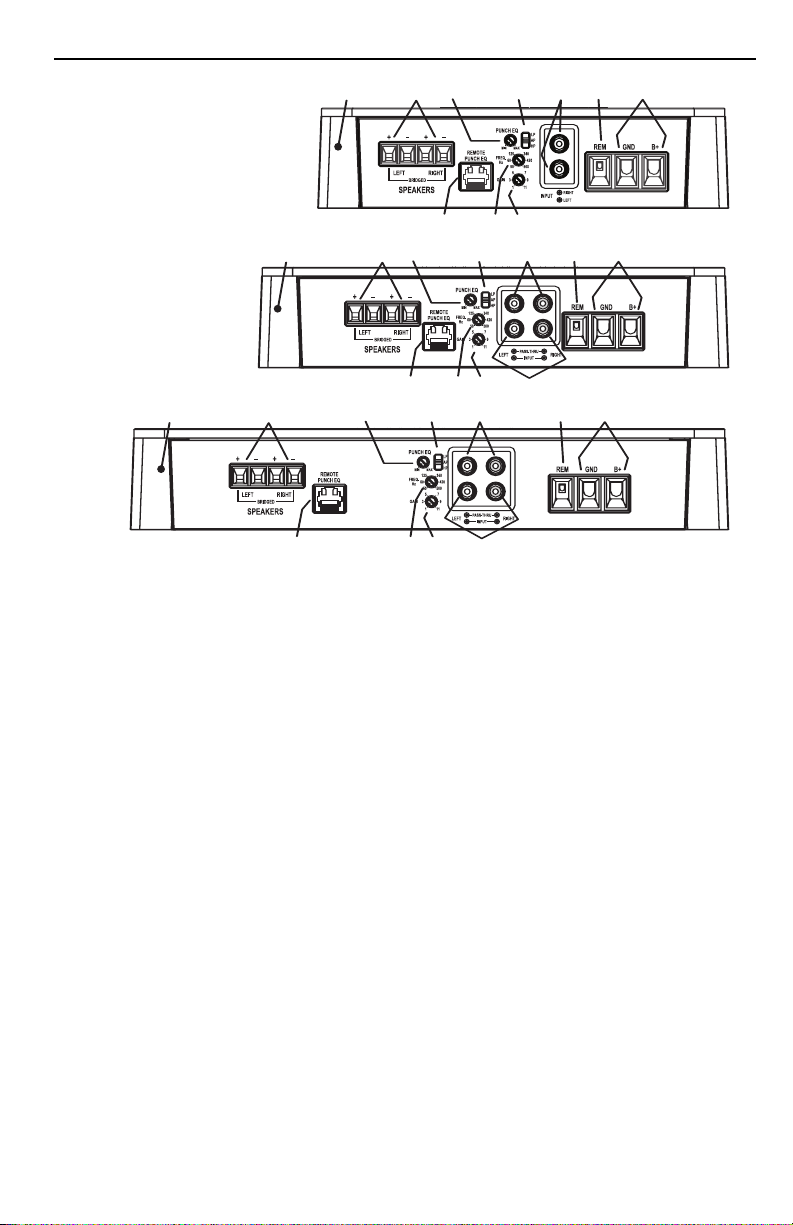
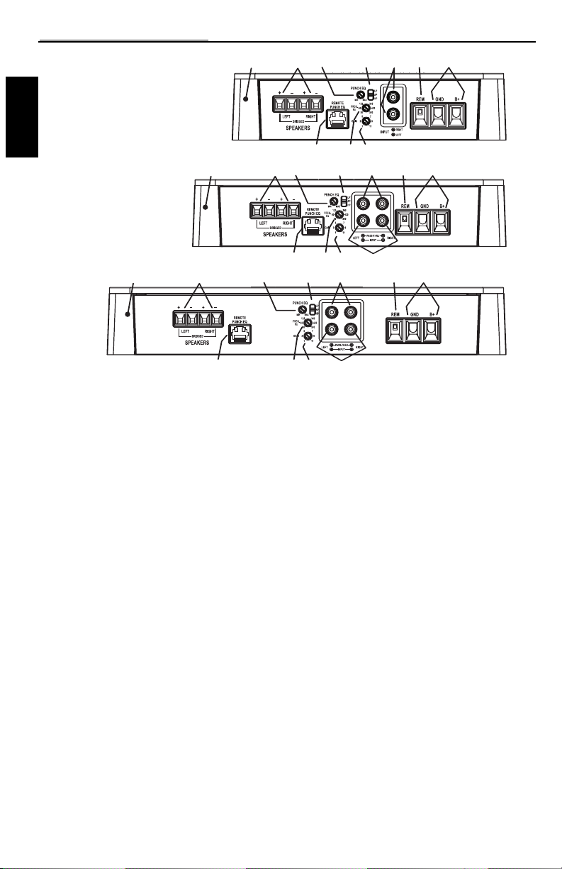
1. Power LED (Top of unit - Not Shown) – This Blue LED illuminates when the unit is turned on.
2. Thermal LED (Top of unit - Not Shown) – This Red LED illuminates if the amplifier internal
components become too hot and engage the thermal protection.The amplifier will shut down to cool
if this occurs.
3. Protect LED (Top of unit - Not Shown) – This Yellow LED illuminates if a short circuit or too low of
an impedance is detected at the speaker connections.The amplifier will automatically shut down if this
occurs.
4. Cast Aluminum Heatsink – The cast aluminum heatsink of the Punch amplifier dissipates heat
generated by the amplifier's circuitry.
5. Speaker Terminals – The heavy duty,nickel-plated clamp wire connectors (+and -) will accept wire
sizes from 8 AWG to 18 AWG.
6. Remote Punch EQ (Optional Controller) – The Remote Punch EQ connection is made with a RJ-45
cable and can be installed in a variety of ways for easy control access.The control is used to boost low
and/or high frequency information to overcome road noise.The remote overrides the Punch EQ on the
amplifier when connected.
NOTE:Previous (prior to 2007) Punch Bass and Para-Punch remotes will not work with these amplifiers.
7. Punch EQ – A Gyrator based Punch EQ that eliminates frequency shift with boost.This works along
with the crossover switch on the amplifier.When set to Low-Pass (LP) operation, this is a variable Bass
Boost. When set to High-Pass (HP) operation, this is a variable Mid-Bass and Treble Boost. When set to
All Pass (AP) operation, both the Bass and Treble frequencies are boosted.
8. Crossover Switch – Selectable switch for High-Pass (HP),All Pass (AP), or Low-Pass (LP) operation.
9. Variable Crossover – Is a built-in 12dB/octave Butterworth filter with a crossover point variable
from 50Hz to 500Hz.
10. Gain Control – The input gain control is preset to match the output of most source units. It can be
adjusted to match output levels from a variety of source units.
11. RCA Pass-Thru Jacks (P400-2 and P500-2 only) – This Pass-Thru provides a convenient source for
daisy-chaining an additional amplifier without running an extra set of RCA cables from the front of the
vehicle to the rear amplifier location.
4
DESIGN FEATURES

5
DESIGN FEATURES
INSTALLATION
INSTALLATION CONSIDERATIONS
The following is a list of tools needed for installation:
Fuse-holder and fuse.
(See specifications for fuse rating)
Volt/Ohm Meter
Wire strippers
Wire crimpers
Wire cutters
#2 Phillips screwdriver
Battery post wrench
Hand held drill w/assorted bits
1/8" diameter heatshrink tubing
Assorted connectors
Adequate Length—Red Power Wire
Adequate Length—Remote Turn-on Wire
Adequate Length—Black Grounding Wire
NOTE:We recommend a 4 AWG wire for use on the power (B+) and ground (GND) connections.
This section focuses on some of the vehicle considerations for installing your new amplifier.
Pre-planning your system layout and best wiring routes will save installation time.When deciding on the
layout of your new system, be sure that each component will be easily accessible for making adjustments.
CAUTION:If you feel unsure about installing this system yourself, have it installed by a
qualified technician.
CAUTION:Before installation, disconnect the battery negative (-) terminal to prevent
damage to the unit, fire and/or possible injury.
Before beginning any installation, follow these simple rules:
1. Be sure to carefully read and understand the instructions before attempting to install the unit.
2. For safety, disconnect the negative lead from the battery prior to beginning the installation.
3. For easier assembly, we suggest you run all wires prior to mounting your unit in place.
4. Route all of the RCA cables close together and away from any high current wires.
5. Use high quality connectors for a reliable installation and to minimize signal or power loss.
6. Think before you drill! Be careful not to cut or drill into gas tanks, fuel lines, brake or hydraulic lines,
vacuum lines or electrical wiring when working on any vehicle.
7. Never run wires underneath the vehicle. Running the wires inside the vehicle provides the best
protection.
8. Avoid running wires over or through sharp edges. Use rubber or plastic grommets to protect any
wires routed through metal,especially the firewall.
9. ALWAYS protect the battery and electrical system from damage with proper fusing. Install the
appropriate fuse holder and fuse on the +12V power wire within 18" (45.7 cm) of the battery
terminal.
10. When grounding to the chassis of the vehicle, scrape all paint from the metal to ensure a good, clean
ground connection. Grounding connections should be as short as possible and always be connected to
metal that is welded to the main body, or chassis, of the vehicle.
12. RCA Input Jacks – The industry standard RCA jacks provide an easy connection for signal level input.
They are nickel-plated to resist the signal degradation caused by corrosion.
13. REM Terminal – The heavy duty, nickel-plated captive c-clamp wire connector will accept wire sizes
from 12 AWG to 24 AWG.This terminal is used to remotely turn-on and turn-off the amplifier when
+12V DC is applied.
14. Power Terminals – The power and ground are nickel-plated captive c-clamp wire connectors and will
accommodate up to 4 AWG wire.
6
INSTALLATION
MOUNTING LOCATIONS
Engine Compartment
Never mount this unit in the engine compartment. Mounting the unit in the engine compartment will void
your warranty.
Trunk Mounting
Mounting the amplifier vertically or inverted will provide adequate cooling of the amplifier.
Mounting the amplifier on the floor of the trunk will provide the best cooling of the amplifier.
Passenger Compartment Mounting
Mounting the amplifier in the passenger compartment will work as long as you provide a sufficient amount
of air for the amplifier to cool itself. If you are going to mount the amplifier under the seat of the vehicle,
you must have at least 1" (2.54cm) of air gap around the amplifier's heatsink.
Mounting the amplifier with less than 1" (2.54cm) of air gap around the amplifier's heatsink in the
passenger compartment will not provide proper cooling and will severely affect the performance of the
amplifier and is strongly not recommended.
BATTERY AND CHARGING
Amplifiers will put an increased load on the vehicle's battery and charging system.We recommend
checking your alternator and battery condition to ensure that the electrical system has enough capacity to
handle the increased load of your stereo system. Stock electrical systems which are in good condition
should be able to handle the extra load of any Punch Series amplifier without problems, although battery
and alternator life can be reduced slightly.To maximize the performance of your amplifier,we suggest the
use of a heavy duty battery and an energy storage capacitor.
WIRING THE SYSTEM
CAUTION:If you do not feel comfortable with wiring your new unit, please see your
local Authorized Rockford Fosgate Dealer for installation.
CAUTION:Before installation, disconnect the battery negative (-) terminal to prevent
damage to the unit, fire and/or possible injury.
CAUTION:Avoid running power wires near the low level input cables, antenna, power
leads, sensitive equipment or harnesses.The power wires carry substantial
current and could induce noise into the audio system.
1. Plan the wire routing.Keep RCA cables close together but isolated from the amplifier's power cables
and any high power auto accessories, especially electric motors.This is done to prevent coupling the
noise from radiated electrical fields into the audio signal.When feeding the wires through the firewall
or any metal barrier, protect them with plastic or rubber grommets to prevent short circuits. Leave
the wires long at this point to adjust for a precise fit at a later time.
NOTE:We recommend a 4 AWG wire for use on the power (B+) and ground (GND) connections.
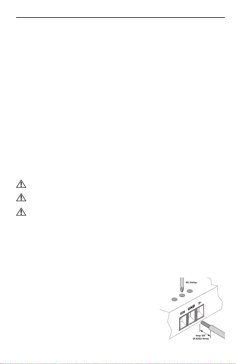
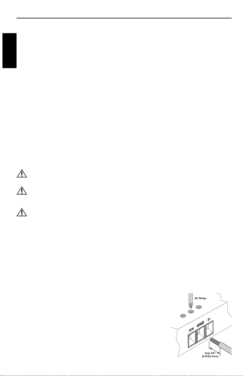
2. Prepare the RED wire (power cable) for attachment to the amplifier by stripping 5/8" of insulation
from the end of the wire. Insert the bared wire into the B+ terminal and tighten the set screw to
secure the cable in place.
NOTE:The B+ cable MUST be fused 18" or less from the vehicle's
battery. Install the fuseholder under the hood and ensure
connections are water tight.
3. Trim the RED wire (power cable) within 18" of the battery and
splice in a inline fuse holder (not supplied). See Specifications for
the rating of the fuse to be used. DO NOT install the fuse at
this time.
4. Strip 1/2" from the battery end of the power cable and crimp a
large ring terminal to the cable. Use the ring terminal to connect
to the battery positive terminal.
7
INSTALLATION
5. Prepare the BLACK wire (Ground cable) for attachment to the amplifier by stripping 5/8" of
insulation from the end of the wire. Insert the bare wire into the GROUND terminal and tighten the
set screw to secure the cable in place. Prepare the chassis ground by scraping any paint from the
metal surface and thoroughly clean the area of all dirt and grease. Strip the other end of the wire and
attach a ring connector. Fasten the cable to the chassis using a
non-anodized screw and a star washer.
NOTE:Keep the length of the BLACK wire (Ground) as short as possible. Always less than 30"(76.2cm).
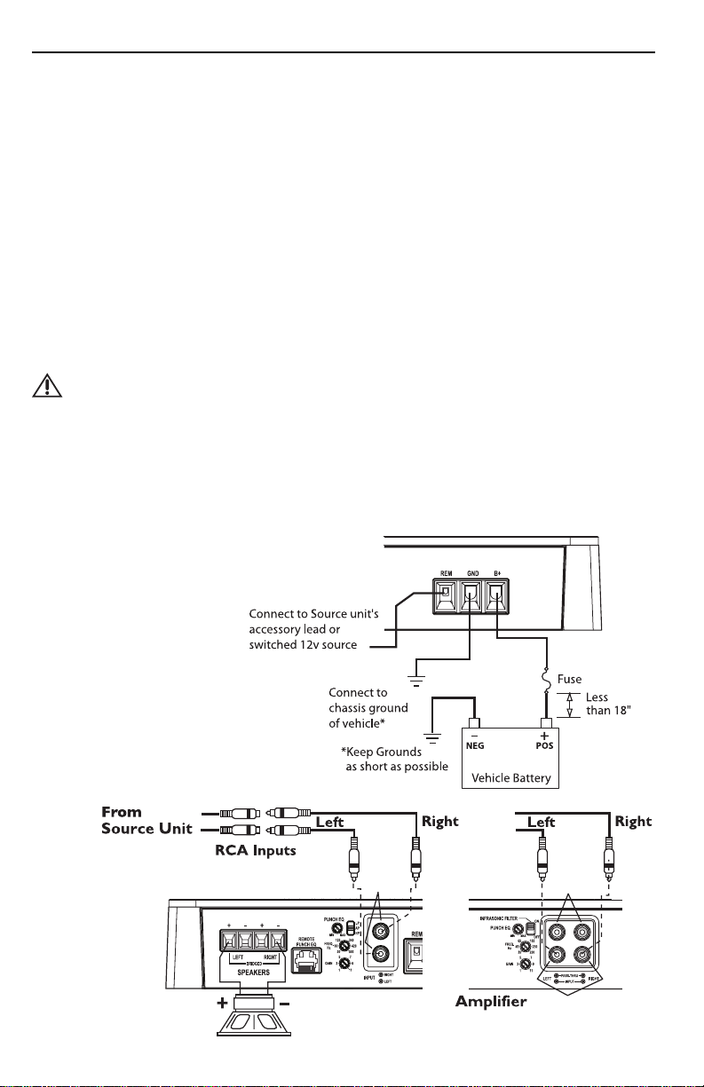
6. Prepare the Remote turn-on wire for for attachment to the amplifier by stripping 5/8" of insulation
from the end of the wire. Insert the bared wire into the REMOTE terminal and tighten the set screw
to secure the wire in place. Connect the other end of the Remote wire to a switched 12 volt positive
source.The switched voltage is usually taken from the source unit's remote amp on lead. If the source
unit does not have this output available, the recommended solution is to wire a mechanical switch in
line with a 12 volt source to activate the amplifier.
7. Securely mount the amplifier to the vehicle or amp rack.Be careful not to mount the amplifier on
cardboard or plastic panels. Doing so may enable the screws to pull out from the panel due to road
vibration or sudden vehicle stops.
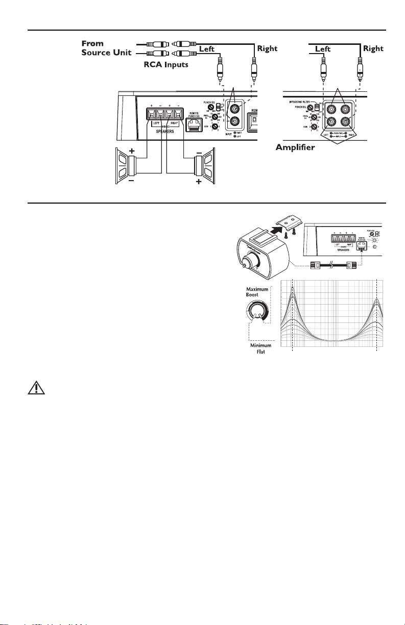
8. Connect from source signal by plugging the RCA cables into the input jacks at the amplifier.
CAUTION:Always ensure power is off or disconnected at the amplifier before
connecting RCA cables. Failure to do so may cause injury, damage to the
amplifier and/or connected components.
9. Connect the speakers. Strip the speaker wires 1/2" and insert into the speaker terminal and tighten
the set screw to secure into place. Be sure to maintain proper speaker polarity. DO NOT chassis
ground any of the speaker leads as unstable operation may result.
10. Perform a final check of the completed system wiring to ensure that all connections are accurate.
Check all power and ground connections for frayed wires and loose connections which could cause
problems. Install inline fuse near battery connection.
NOTE:Follow the diagrams for
proper signal polarity.
INPUT
P300-2
P400-2
P500-2
INPUT
PASS-THRU
OR
P200-2
See Specifications
for Fuse Rating
Power
Connection
Bridged/
Mono Wiring
8
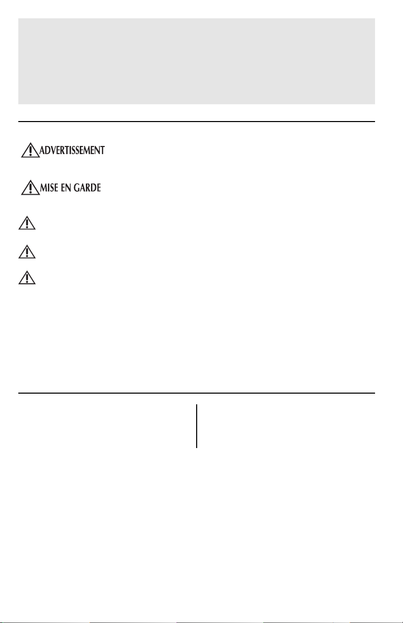
REMOTE PUNCH EQ (Option)
NOTE:Previous (prior to 2007) Punch Bass and Para-
Punch remotes will not work with these amplifiers.
NOTE:Use the instructions that came with the remote for
a variety of mountings that fit your preference.
Quick Install
1. Using the screws supplied, install the mounting clip.
2. Slip the remote onto the mounting clip until it snaps
into place.
3. Route and connect the cable to the remote and
amplifier.
Operation
6. Operation works the same as Punch EQ, see below.
NOTE:Connecting the optional remote overrides the Punch EQ control on the amplifier.
CAUTION:Overexcursion and subsequent damage may occur at high levels of boost.
OPERATION
PUNCH EQ
This works along with the crossover switch on the amplifier.
When set to Low-Pass (LP) operation, this is a variable Bass Boost.
When set to High-Pass (HP) operation, this is a variable Mid-Bass and Treble Boost.
When set to All Pass (AP) operation, both the Bass and Treble frequencies are boosted.
Set this to your personal preference while listening to the system.
NOTE:Connecting the optional remote overrides the Punch EQ control on the amplifier.
ADJUSTING CROSSOVER FREQUENCY
Placing the crossover switch in the HP position sets the amplifier to the High Pass mode, enabling
frequencies above the cut-off point to pass, adjustable between 50-500Hz.
Placing the crossover switch in the AP position sets the amplifier to the All Pass mode, preventing any
crossover adjustment, allowing all frequencies to pass.
Placing the crossover switch in the LP position sets the amplifier to the Low Pass mode, enabling
frequencies below the cut-off point to pass, adjustable between 50-500Hz.
Turn the crossover adjustment knob all the way down.With the system playing, turn the crossover
adjustment knob up slowly until the desired crossover point is achieved.
INPUT
P300-2
P200-2 P400-2
P500-2
INPUT
PASS-THRU
OR
2-Channel Wiring
dB
+20
-2
-0
+2
+4
+6
+8
+10
+12
+14
+16
+18
20 20k50 100 200 500 1k 2k 5k 10k
Hz
Bass Treble
INSTALLATION

9
OPERATION
TROUBLESHOOTING
NOTE:If you are having problems after installation follow the Troubleshooting procedures below.
Procedure 1: Check Amplifier for proper connections.
Verify that POWER light is on. If POWER light is on skip to Step 3, if not continue.
1. Check in-line fuse on battery positive cable. Replace if necessary.
2. Check fuse(s) on amplifier. Replace if necessary.
3. Verify that Ground connection is connected to clean metal on the vehicle’s chassis. Repair/replace if
necessary.
4. Verify there is 9 to 16 Volts present at the positive battery and remote turn-on cable.Verify quality
connections for both cables at amplifier, stereo, and battery/fuseholder. Repair/replace if necessary.
Procedure 2: Protect or Thermal light is on.
1. If the Protect light is on, this is a sign of a possible short in the speaker connections. Check for
proper speaker connections and use an ohm meter to check for possible shorts in the speaker wiring.
Too low of a speaker impedance may also cause Protect to light.
2. If the Thermal light is on, check for proper speaker impedance, rewire if needed.This can also be a sign
of driving the amplifier at very high power levels without adequate airflow around the amplifier. Shut
off the system and allow amplifier to cool. Check that the vehicle charging system is maintaining
proper voltage. If the previous items do not solve the problem, a fault may be in the amplifier,call
customer service for support.
Procedure 3: Check Amplifier for audio output.
1. Verify good RCA input connections at stereo and amplifier. Check entire length of cables for kinks,
splices, etc.Test RCA inputs for AC volts with stereo on. Repair/replace if necessary.
2. Disconnect RCA input from amplifier. Connect RCA input from test stereo directly to amplifier input.
Procedure 4: Check Amplifier if you experience Turn-on Pop.
1. Disconnect input signal to amplifier and turn amplifier on and off.
2. If the noise is eliminated, connect the REMOTE lead of amplifier to source unit with a delay turn-on
module.
OR
1. Use a different 12 Volt source for REMOTE lead of amplifier (i.e. battery direct).
2. If the noise is eliminated, use a relay to isolate the amplifier from noisy turn-on output.
Procedure 5: Check Amplifier if you experience excess Engine Noise.
1. Route all signal carrying wires (RCA, Speaker cables) away from power and ground wires.
OR
ADJUSTING GAIN
To adjust the gain setting, turn the amplifier gains all the way down (counterclockwise).Turn the source unit volume up until distortion is audible and then turn
it down a bit until the distortion is inaudible.This will be about all the way up on
most source units. Next, increase the amplifier gain setting until adequate volume is
achieved.
NOTE:Best signal to noise and dynamic range are realized with the gain at
minimum. Most users find adequate gain and volume is achieved at about
halfway in the adjustment range.
CAUTION:Avoid setting the amplifier gain very high as noise and
distortion will increase significantly.
NOTE:For a more in depth setting procedure, contact Rockford Technical
Support.
Crossover Switch

10
SPECIFICATIONS
MODEL- Punch P200-2 P300-2 P400-2 P500-2
Continuous Power Rating (RMS) - Measured at 14.4 Battery Volts
4 Load Per Channel 50 Watts x 2 75 Watts x 2 100 Watts x 2 125 Watts x 2
2 Load Per Channel 100 Watts x 2 150 Watts x 2 200 Watts x 2 250 Watts x 2
4 Load Bridged 200 Watts x 1 300 Watts x 1 400 Watts x 1 500 Watts x 1
Dimensions: Height 2.25" (5.71cm) 2.25" (5.71cm) 2.25" (5.71cm) 2.25" (5.71cm)
Width 7.625" (19.37cm) 7.625" (19.37cm) 7.625" (19.37cm) 7.625" (19.37cm)
Length 9.0" (22.80cm) 9.0" (22.80cm) 10.25" (26.03cm) 13.02" (33.07cm)
Battery Fuse Rating (Amp) 40A 50A 80A 100A
External (Not Supplied)
“A” Weighted Signal to Noise Ratio
Referenced to 1 Watt into 4 ohms ≥85 dB
“A” Weighted Signal to Noise Ratio
Referenced to rated output into 4 ohms ≥105 dB
Crossover Slope 12dB/octave Butterworth
Crossover Frequency variable from 50Hz to 500Hz
Frequency Response 20Hz to 20kHz ±1dB
Signal Voltage Adjustment Range Variable from 150mV to 5V (RCA Input)
Protection NOMAD - Internal analog-computer output protection circuitry
limits power in case of overload, plus short protection.
Thermal switch shuts down the amplifier in case of overheating.
Equalization PEQ (Punch Equalization) Variable from 0dB to +18dB @ 45Hz and/or
0dB to +12dB @ 12kHz
Input Impedance 20K ohms
Operating Voltage 9 to 16 Volts DC
Balanced Inputs Yes
CMRR (Common Mode Rejection Ratio) >55dB @ 1kHz
Damping Factor >200
THD+N (Total Harmonic Distortion + Noise) < 0.1 @ 2 ohm and < 0.05 @ 4 ohm
These specifications are Amplifier Power Standard CEA-2006 Compliant
Specifications subject to change without notice
2. Bypass any and all electrical components between the stereo and the amplifier(s). Connect stereo
directly to input of amplifier. If noise goes away the unit being bypassed is the cause of the noise.
OR
3. Remove existing ground wires for all electrical components. Reground wires to different locations.
Verify that grounding location is clean, shiny metal free of paint, rust etc.
OR
4. Add secondary ground cable from negative battery terminal to the chassis metal or engine block of
vehicle.
OR
5. Have alternator and battery load tested by your mechanic.Verify good working order of vehicle
electrical system including distributor, spark plugs, spark plug wires, voltage regulator etc.
TROUBLESHOOTING

11
LIMITED WARRANTY INFORMATION
Rockford Corporation offers a limited warranty on Rockford Fosgate products on the
following terms:
Length of Warranty
Source Units, Speakers, Signal Processors and PUNCH Amplifiers – 1 Year
POWER Amplifiers – 2 Years
Any Factory Refurbished Product – 90 days (receipt required)
What is Covered
This warranty applies only to Rockford Fosgate products sold to consumers by Authorized
Rockford Fosgate Dealers in the United States of America or its possessions. Product
purchased by consumers from an Authorized Rockford Fosgate Dealer in another country are
covered only by that country’s Distributor and not by Rockford Corporation.
Who is Covered
This warranty covers only the original purchaser of Rockford product purchased from an
Authorized Rockford Fosgate Dealer in the United States. In order to receive service, the
purchaser must provide Rockford with a copy of the receipt stating the customer name, dealer
name, product purchased and date of purchase.
Products found to be defective during the warranty period will be repaired or replaced
(with a product deemed to be equivalent) at Rockford's discretion.
What is Not Covered
1. Damage caused by accident, abuse, improper operations, water, theft,shipping
2.Any cost or expense related to the removal or reinstallation of product
3. Service performed by anyone other than Rockford or an Authorized Rockford Fosgate
Service Center
4.Any product which has had the serial number defaced, altered, or removed
5. Subsequent damage to other components
6.Any product purchased outside the U.S.
7.Any product not purchased from an Authorized Rockford Fosgate Dealer
Limit on Implied Warranties
Any implied warranties including warranties of fitness for use and merchantability are limited in
duration to the period of the express warranty set forth above.Some states do not allow limitations
on the length of an implied warranty, so this limitation may not apply. No person is authorized to
assume for Rockford Fosgate any other liability in connection with the sale of the product.
How to Obtain Service
Contact the Authorized Rockford Fosgate Dealer you purchased this product from.
If you need further assistance, call 1-800-669-9899 for Rockford Customer Service.You must
obtain an RA# (Return Authorization number) to return any product to Rockford Fosgate.
You are responsible for shipment of product to Rockford.
EU Warranty
This product meets the current EU warranty requirements, see your Authorized dealer for
details.

2
Français
INTRODUCTION
TABLE DES MATIÈRES
Cher client,
Toutes nos félicitations pour avoir acheté la meilleure marque d'amplificateurs pour automobile. Chez Rockford
Fosgate nous sommes des mordus de la reproduction musicale à son meilleur. C’est pourquoi nous sommes
heureux que vous ayez choisi notre produit. Des années d’expertise en ingénierie, de savoir-faire et d’essais poussés
nous ont permis de créer une vaste gamme de produits capables de reproduire toute la clarté et la richesse
musicales que vous méritez.
Pour obtenir les meilleurs résultats, nous vous recommandons de faire installer votre nouvel appareil par un
distributeur agréé Rockford Fosgate formé spécialement par notre Institut de formation technique Rockford (RTTI).
Prenez soin de lire la garantie et conservez votre reçu ainsi que l’emballage d'origine pour usage ultérieur.
Pour monter un excellent système, il ne suffit pas de posséder un super produit et d’assurer une installation
qualifiée compétente.Vous devez veiller à ce que votre installateur utilise des accessoires d’origine fournis par
Rockford Fosgate. Rockford Fosgate a tout ce qu’il vous faut, des câbles RCA aux câbles de haut-parleur, en
passant par les câbles d’alimentation et les connecteurs de batterie. Insistez pour les avoir! Après tout, votre
nouveau système ne mérite rien de moins.
Pour compléter votre nouvelle image Rockford Fosgate, commandez des accessoires Rockford tels que T-shirts,
vestes, chapeaux et lunettes de soleil.
Pour obtenir une brochure gratuite sur les produits Rockford Fosgate et les accessoires Rockford,
Visitez notre site Web : www.rockfordfosgate.com
ou, aux États-Unis, appelez le 1-800-669-9899 ou envoyez un fax au 1-800-398-3985.
Pour tous les autres pays, appelez le +001-480-967-3565 ou faxez au +001-480-967-8132.
PRATIQUEZ UNE ÉCOUTE SANS RISQUES
MD
Une exposition continue à des niveaux de pression acoustique supérieurs à 100 dB peut
causer une perte d'acuité auditive permanente. Les systèmes audio de forte puissance
pour auto peuvent produire des niveaux de pression acoustique bien au-delà de 130 dB.
Faites preuve de bon sens et pratiquez une écoute sans risques
NOTE : consultez chaque section pour de plus amples informations.
Si vous avez encore des questions à propos de ce produit, même après avoir lu ce manuel, contactez votre
distributeur agréé Rockford Fosgate. Si vous avez besoin d'aide, appelez-nous au
1-800-669-9899.Veuillez avoir les numéros de modèle et de série, ainsi que la date d'achat de l'appareil à portée
de main lorsque vous appelez.
Le numéro de série est indiqué sur l’extérieur de l’emballage.Veuillez l’inscrire ci-dessous dans l'espace réservé à
cet effet. Il permettra de vérifier votre garantie et de retrouver votre appareil en cas de vol.
Numéro de série : ___________________________________
Numéro de modèle :__________________________________
Introduction. . . . . . . . . . . . . . . . . . . . . . . . . 2
Consignes de sécurité . . . . . . . . . . . . . . . . . 3
Particularités techniques. . . . . . . . . . . . . 4-5
Installation . . . . . . . . . . . . . . . . . . . . . . . . 5-8
Considérations concernant l'installation . . . 5
Emplacements de montage . . . . . . . . . . . . . . 5
Batterie et charge . . . . . . . . . . . . . . . . . . . . . 6
Câblage du système. . . . . . . . . . . . . . . . . . . . 6
Fonctionnement. . . . . . . . . . . . . . . . . . . . 8-9
Télécommande d'égaliseur Punch (option) . 8
Égaliseur Punch . . . . . . . . . . . . . . . . . . . . . . . 8
Réglage de la fréquence du filtre passif . . . . 8
Réglage du gain . . . . . . . . . . . . . . . . . . . . . . . 9
Dépannage . . . . . . . . . . . . . . . . . . . . . . . 9-10
Caractéristiques . . . . . . . . . . . . . . . . . . . . 10
Informations sur la garantie limitée . . . . 11
2008 Rockford Corporation.Tous droits réservés.
Rockford Fosgate, le logo Rockford Fosgate, le logo POWER et le logo PUNCH sont des marques
déposées ou des marques de commerce de Rockford Corporation.
3
CONSIGNES DE SÉCURITÉ
AVANT DE COMMENCER
Bienvenue à Rockford Fosgate ! Ce manuel vise à informer le propriétaire, le vendeur et l’installateur de
l’appareil.Si vous désirez apprendre rapidement comment installer ce produit, consultez la section Installation
du manuel. Reportez-vous à la Table des matières pour d’autres informations. Nous nous efforçons de faire
en sorte que toutes les informations contenues dans ce manuel soient à jour. Mais comme nous améliorons
constamment nos produits, nous nous réservons le droit de modifier ces informations sans aucun préavis.
Visitez notre site Web pour obtenir les dernières informations sur tous les produits Rockford.
www.rockfordfosgate.com
Le kit de matériel inclus avec chaque amplificateur contient le matériel de montage nécessaire pour fixer
l'ampli au véhicule.
CONTENU DE L'EMBALLAGE
Le symbole accompagnant le mot « AVERTISSEMENT » signale à
l'utilisateur la présence d’instructions importantes. Le non-respect de
ces instructions causera des blessures graves ou la mort.
Le symbole accompagnant l’expression « MISE EN GARDE » signale
à l'utilisateur la présence d’instructions importantes. Le non-respect de
ces instructions peut causer des blessures ou endommager l’appareil.
MISE EN GARDE : pour éviter des blessures et ne pas endommager l'appareil,
veuillez lire et suivre les instructions du manuel.Nous espérons
que ce système vous procurera du plaisir et non des tracas.
MISE EN GARDE : si vous vous sentez incapable d’installer l’appareil vous-même,
confiez la tâche à un technicien Rockford Fosgate qualifié.
MISE EN GARDE : avant d'entamer l'installation, déconnectez la broche négative (-)
de la batterie pour éviter tout risque de blessures, d’incendie ou
de dommages à l'appareil.
Amplificateur Punch à 2 voies modèle
P200-2, P300-2, P400-2 ou modèle P500-2
Manuel d'installation et d'utilisation
Kit de matériel de montage
4
Français
PARTICULARITÉS TECHNIQUES
1. DEL d'alimentation (au-dessus de l'appareil - non montré) – Cette DEL bleue s'illumine lorsque
l'appareil est allumé.
2. DEL thermique (au-dessus de l'appareil - non illustré) - Cette DEL rouge s'illumine si les composants
internes de l'ampli surchauffent et déclenchent la protection thermique. Si cela se produit, l'ampli s'éteint
pour refroidir.
3. DEL de protection (au-dessus de l'appareil - non montré) - Cette DEL jaune s'illumine si un
court-circuit ou une impédance trop basse est détecté au niveau des connexions de haut-parleur. L'ampli
s'éteint automatiquement si cela se produit.
4. Dissipateur thermique en aluminium coulé – Le dissipateur thermique en aluminium coulé de
l'amplificateur Punch dissipe la chaleur générée par les circuits de l'amplificateur.
5. Bornes de haut-parleur - Les connecteurs de fil robustes nickelés (+ et -) acceptent des câbles de calibre 8 à
18 AWG.
6. Télécommande d'égaliseur Punch (télécommande en option) - La connexion de la
télécommande d'égaliseur Punch se fait à l'aide d'un câble RJ-45 et peut être effectuée de différentes
façons de manière à permettre un accès facile. Cette commande permet d'amplifier les basses et hautes
fréquences afin de couvrir le bruit de la route. La télécommande remplace l'égaliseur Punch de l'ampli une
fois connectée.
7. Égaliseur Punch - Égaliseur Punch à base de gyrateur permettant d'éliminer le déplacement de
fréquence produit par l'amplification. Fonctionne de pair avec le commutateur de filtre passif. Assure une
amplification variable des basses en mode LP (passe-bas). Assure une amplification variable des médium/basses et
des aigus en mode HP (passe-haut). En mode AP (passe-tout),les fréquences des basses et des aigus sont
amplifiées.
8. Commutateur de filtre passif - Commutateur sélectable permettant de sélectionner les modes passe-
haut (HP), passe-tout (AP) ou passe-bas (LP).
9. Filtre variable – Les amplificateurs sont dotés d'un filtre de Butterworth intégré de 12 dB/octave dont
le point de fréquence varie entre 50 Hz et 500 Hz.
10. Commande de gain – La commande de gain d'entrée est préréglée de manière à correspondre à la sortie de
la plupart des unités source. Elle peut être réglée en fonction d'une variété d'unités source.
11. Extension ampli RCA – L'extension ampli permet de connecter en guirlande un second ampli en évitant
d'acheminer des câbles RCA supplémentaires de l'avant du véhicule vers l'emplacement de l'ampli arrière.
4578
9610
13 14
P400-2
11
12
4578
9610
13 14
P500-2
11
12
4578
9610
13 14
P200-2
P300-2
12

5
PARTICULARITÉS TECHNIQUES
INSTALLATION
CONSIDÉRATIONS CONCERNANT L’INSTALLATION
Voici la liste d’outils requis pour l’installation :
Porte-fusible et fusible.
(Voir les spécifications concernant la
capacité des fusibles)
Voltmètre-ohmmètre
Pince à dénuder
Pince à sertir
Coupe-fils
Tournevis à embout cruciforme no2
Clé de borne de batterie
Perceuse à main avec mèches assorties
Tube thermorétrécissable de 1/8 po de
diamètre
Connecteurs assortis
Longueur adéquate — Fil d’alimentation rouge
Longueur adéquate — Fil d’allumage à distance
Longueur adéquate — Fil de masse noir
REMARQUE : Nous recommandons l'utilisation d'un fil de 4 AWG pour les prises d'alimentation (B+) et
de masse (GND).
Cette section traite de points concernant le véhicule dont il faut tenir compte pour l’installation de votre nouvel
ampli.Vous sauverez du temps en planifiant à l’avance la disposition du système et du câblage. Assurez-vous, entre
autres, que chaque composant du système est facilement accessible pour les réglages.
MISE EN GARDE : si vous vous sentez incapable d’installer l’appareil vous-même,
confiez la tâche à un technicien qualifié.
MISE EN GARDE : avant d'entamer l'installation, déconnectez la broche négative (-)
de la batterie pour éviter tout risque de blessures, d’incendie ou
de dommages à l'appareil.
Avant de commencer l’installation, suivez ces règles toutes simples :
1. Prenez soin de bien lire et comprendre les instructions avant d’installer l’appareil.
2. Par mesure de sécurité, veuillez débrancher le fil négatif de la batterie avant de commencer l’installation.
3. Pour faciliter le montage, nous vous suggérons de dérouler tous les fils avant d’installer l’appareil.
4. Acheminez tous les câbles RCA de façon groupée, à l’écart des fils à courant élevé.
5. Utilisez des connecteurs de haute qualité pour assurer une installation fiable et minimiser la perte de signal
ou de puissance.
6. Réfléchissez avant de percer quoique ce soit! Faites attention de ne pas couper ou percer le réservoir
d’essence, les conduites de carburant,de frein, hydrauliques ou de dépression, ou le câblage électrique
lorsque vous travaillez sur un véhicule.
7. Ne faites jamais passer les fils sous le véhicule. Il vaut mieux les installer à l’intérieur du véhicule pour
assurer une meilleure protection.
8. Évitez de faire passer les fils par dessus ou à travers des bords tranchants.Tout fil acheminé à travers du
métal, un pare-feu en particulier, doit être protégé avec des bagues en caoutchouc ou plastique.
9. Protégez TOUJOURS la batterie et le circuit électrique des dommages potentiels à l’aide de fusibles.Installez
un porte-fusible et un fusible appropriés sur le câble d’alimentation de +12 V à moins de 45,7 cm (18 po) de
la borne de batterie.
10. Préparez la masse du châssis en grattant toute trace de peinture de la surface métallique afin d’assurer une
bonne mise à la masse. Les connexions de masse doivent être aussi courtes que possible et toujours
connectées à du métal soudé à la carrosserie ou au châssis du véhicule.
12. Prises d'entrée RCA – Les prises RCA de norme industrielle permettent une connexion facile pour les
entrées de signaux. Ils sont plaqués de nickelés pour résister à la détérioration de signal due à l'effet de la
corrosion.
13. Borne REM - Le connecteur de fil robuste nickelé en C accepte des câbles de calibre 12 à 24 AWG.Cette
borne permet d'allumer et d'éteindre à distance l'amplificateur lorsqu'un courant de +12 V c.c. est envoyé.
14. Bornes d'alimentation - Les connexions d'alimentation et de masse sont nickelées et peuvent accueillir des
câbles de calibre allant jusqu'à 4 AWG.
6
Français
INSTALLATION
BATTERIE ET CHARGE
Les amplificateurs exercent une charge accrue sur la batterie et le système de charge du véhicule. Nous vous
conseillons de vérifier l'état de l'alternateur et de la batterie pour vous assurer que le système électrique puisse
supporter la charge accrue de votre système stéréo.Les systèmes électriques ordinaires en bon état sont
normalement capables de fournir sans problème la charge supplémentaire requise par les amplis Punch.Toutefois,
la durée de vie de la batterie et de l'alternateur peut s'en trouver affectée légèrement.Pour maximiser la
performance de votre ampli,nous vous suggérons d'utiliser une batterie à usage intensif et un condensateur de
stockage d'énergie.
CÂBLAGE DU SYSTÈME
MISE EN GARDE : si vous ne vous sentez pas à l’aise pour effectuer vous-même le
câblage de votre nouvel appareil, veuillez confier l’installation à votre
distributeur agréé Rockford Fosgate.
MISE EN GARDE : avant d'entamer l'installation, déconnectez la broche négative (-) de la
batterie pour éviter tout risque de blessures, d’incendie ou de
dommages à l'appareil.
MISE EN GARDE : évitez de faire passer les fils d’alimentation près des câbles d’entrée
de signaux faibles, de l’antenne, des câbles d'alimentation, des
équipements ou faisceaux sensibles. Les fils d’alimentation
transportent un courant élevé et peuvent produire du bruit dans le
système audio.
1. Planifiez l’acheminement des fils. Gardez les câbles RCA ensemble mais en les isolant des câbles d’alimentation de
l’ampli et des autres accessoires automobiles de forte puissance, particulièrement les moteurs électriques, pour
éviter que le signal audio ne subisse d'interférence de bruit provenant de champs de rayonnement électriques. Si
vous faites passer les fils par un pare-feu ou autre barrière métallique, protégez-les à l’aide de bagues en caoutchouc
ou en plastique pour éviter les courts-circuits. Conservez toute la longueur des fils pour l’instant.Vous l’ajusterez
plus tard.
REMARQUE :
Nous recommandons l'utilisation d'un fil de 4 AWG pour les prises d'alimentation (B+) et de
masse (GND).
2. Préparez le fil ROUGE (câble d'alimentation) qui devra être relié à l'ampli en dénudant 5/8 po (1,6 cm) de son
extrémité. Insérez la partie dénudée dans la borne B+, puis fixez le fil en vissant
la vis sans tête.
REMARQUE : Le câble B+ DOIT comporter un fusible à 18 po (45,7 cm) ou
moins de la batterie du véhicule. Installez le porte-fusible sous le
capot et assurez-vous que les connexions sont étanches.
3. Coupez le fil ROUGE (câble d'alimentation) à moins de 18 po (45,7 cm) de la
batterie et épissez un porte-fusible en ligne.Voir les Spécifications en ce qui
concerne la capacité du fusible à utiliser. N'INSTALLEZ PAS le fusible pour
l'instant.
4. Dénudez 1/2 po de l’extrémité de batterie du câble d’alimentation et sertissez
une grosse cosse à anneau sur le câble. Connectez la cosse à la borne positive
de la batterie. N’installez pas le fusible pour l'instant.
EMPLACEMENTS DE MONTAGE
Compartiment moteur
Ne montez jamais cet appareil dans le compartiment moteur. Cela entraînerait l’annulation de la garantie.
Montage dans le coffre
Un montage vertical ou inversé de l'ampli assure un refroidissement adéquat.
Le montage de l'ampli sur le plancher du coffre assure un refroidissement optimal.
Montage dans l’habitacle
Le montage de l’ampli dans l’habitacle passager est acceptable à condition qu’il reçoive suffisamment d’air
pour se refroidir. Si vous comptez installer l’ampli sous le siège du véhicule, prévoyez un écartement d’au
moins 2,54 cm (1 po) autour du dissipateur thermique de l’ampli.
Un écartement inférieur à cela n’assure pas un refroidissement satisfaisant, nuit à la performance de l’ampli
et est, pas conséquent, fortement déconseillé.

5. Préparez le fil NOIR (câble de mise à la masse) qui devra être relié à l’ampli en dénudant 5/8 po (1,6 cm) de son
extrémité. Insérez la partie dénudée dans la borne GND, puis fixez le fil en vissant la vis sans tête. Préparez la masse
du châssis en grattant toute trace de peinture de la surface métallique et en nettoyant soigneusement pour éliminer
tout dépôt de saleté et de graisse. Dénudez l’autre extrémité du fil et fixez un connecteur en anneau. Fixez le câble
au châssis à l’aide d’une vis non anodisée et une rondelle en étoile.
REMARQUE : Gardez le fil NOIR (masse) aussi court que possible.Toujours inférieur à 30 po (76,2 cm).
6. Préparez le fil d'activation REM qui devra être relié à l'ampli en dénudant 1,6 cm 5/8 po (1,6 cm) de son extrémité.
Insérez la partie dénudée dans la borne REM, puis fixez le fil en vissant la vis sans tête. Connectez l'autre extrémité
du fil REM à une source positive commutée de 12 volts.La tension commutée provient généralement du câble
d'allumage d'ampli de la source audio.Si la source audio ne comporte pas une telle sortie, nous recommandons de
raccorder un interrupteur mécanique en ligne avec une source de 12 volts pour activer l'ampli.
7. Montez solidement l’ampli sur le véhicule ou le rack d’ampli. Prenez soin de ne pas le fixer sur des panneaux en
carton ou en plastique. Les vis pourraient en effet se décoller des panneaux sous l’effet des vibrations de la route
ou des arrêts soudains du véhicule.
8. Connectez le signal à l'ampli en branchant les câbles RCA dans les prises d'entrée de l'ampli.
MISE EN GARDE : Assurez-vous toujours que l'ampli est éteint ou débranché avant de
connecter les câbles RCA.Toute négligence à cet égard peut causer
des blessures ou endommager l'ampli et/ou les composants qui lui
sont connectés.
9. Connectez les haut-parleurs : dénudez les fils des haut-parleurs de 1/2 po et insérez la partie dénudée dans la borne
du haut-parleur, puis serrez la vis sans tête pour fixer le tout.Veillez à respecter la polarité des haut-parleurs.NE
mettez PAS les fils de haut-parleur à la masse sur le châssis car cela pourrait causer un fonctionnement instable.
10. Effectuez une vérification finale du câblage pour vous assurer que toutes les connexions sont bien mises.Vérifiez
toutes les connexions d’alimentation et de mise à la masse en vue de fils effilochés et de connexions desserrées
pouvant causer des problèmes. Installez le fusible en ligne près de la connexion de la batterie.
REMARQUE : vérifiez les polarités de signal à l’aide des schémas.
INPUT
P300-2
P400-2
P500-2
INPUT
PASS-THRU
OR
P200-2
7
INSTALLATION
Ponté
mono
Connexion
d'alimentation

INPUT
P300-2
P200-2 P400-2
P500-2
INPUT
PASS-THRU
OR
TÉLÉCOMMANDE D'ÉGALISEUR PUNCH (en option)
REMARQUE : Les modèles précédents (antérieurs à 2007) de
télécommandes de basses Punch et Para-Punch
ne fonctionneront pas avec ces amplificateurs.
REMARQUE : Suivez le mode d'emploi livré avec la
télécommande pour choisir parmi les différents
types de montage celui que vous préférez.
Installez Vite
1. Servez-vous des vis fournies pour installer l'attache de
fixation.
2. Glissez la télécommande sur l'attache de fixation jusqu'à ce
qu'elle se mette en place d'un déclic.
3. Placez le câble, reliez à la télécommande et à l'amplificateur.
Fonctionnement
4. Fonctionnement identique à celui de l'égaliseur Punch, voir
ci-dessous.
REMARQUE : Une fois connectée, la télécommande
d'égaliseur Punch en option remplace la commande de l'égaliseur Punch sur l'ampli.
MISE EN GARDE : Une forte amplification peut produire un excès de mouvement de la
membrane, ce qui peut l'endommager.
dB
+20
-2
-0
+2
+4
+6
+8
+10
+12
+14
+16
+18
20 20k50 100 200 500 1k 2k 5k 10k
Hz
Bass Treble
8
Français
FONCTIONNEMENT
ÉGALISEUR PUNCH
Fonctionne de pair avec le commutateur de filtre passif.
Assure une amplification variable des basses en mode LP (passe-bas).
Assure une amplification variable des médium/basses et des aigus en mode HP (passe-haut).
En mode AP (passe-tout), les fréquences des basses et des aigus sont amplifiées.
Réglez-le selon votre goût tout en écoutant le système.
REMARQUE : Une fois connectée,la télécommande d'égaliseur Punch en option remplace la commande de
l'égaliseur Punch sur l'ampli.
RÉGLAGE DE LA FRÉQUENCE DU FILTRE PASSIF
Lorsque le sélecteur est en position HP, l'amplificateur est en mode passe-haut,ce qui laisse passer les fréquences
situées au-dessus du point de coupure, réglable de 50 à 500 Hz.
Lorsque le sélecteur est en position AP, l'amplificateur est en mode passe-tout,ce qui empêche tout filtrage et laisse
passer toutes les fréquences.
Lorsque le sélecteur est en position LP, l'amplificateur est en mode passe-bas,ce qui laisse passer les fréquences
situées au-dessous du point de coupure, réglable de 50 à 500 Hz.
Baissez complètement le niveau du filtre. Le système audio étant en fonctionnement, augmentez le niveau du filtre
graduellement jusqu'à atteindre le point de fréquence voulu.
Câblage à 2 voies
INSTALLATION

9
DÉPANNAGE
REMARQUE : si vous éprouvez des difficultés après l’installation,appliquez les procédures de dépannage ci-dessous.
Procédure 1 :vérifiez que les connexions de l’ampli sont bien mises.
Vérifiez que le voyant POWER est allumé. Si c'est le cas, passez à l'étape 3,sinon poursuivez.
1. Vérifiez le fusible en ligne du câble positif de batterie. Effectuez un remplacement au besoin.
2. Vérifiez les fusibles de l'ampli. Effectuez un remplacement au besoin.
3. Vérifiez que la connexion de mise à la masse est branchée à une surface métallique propre du châssis du véhicule.Procédez à
une réparation ou un remplacement si nécessaire.
4. Vérifiez la présence d'un courant de 9 à 16 volts au niveau de la borne positive de la batterie et du câble d'allumage à distance.
Vérifiez la qualité des connexions des deux câbles au niveau de l'ampli,de la stéréo,de la batterie et du porte-fusible. Procédez à
une réparation ou un remplacement si nécessaire.
Procédure 2 :Le voyant de protection ou thermique est allumé.
1. Si le voyant de protection est activé, cela indique la présence possible d'un court-circuit dans les connexions de hautparleur.Vérifiez si les connexions des haut-parleurs sont bonnes et servez-vous d'un ohm-mètre pour voir s'il y a des
courts-circuits dans le câblage des haut-parleurs. Le voyant de protection peut s'allumer si l'impédance de haut-parleur
est trop basse.
2. Si le voyant thermique est allumé, vérifiez que l'impédance de haut-parleur est bonne.Refaites le câblage au besoin.
Cela peut également indiquer que l'ampli fonctionne à très forte puissance alors que la circulation d'air autour de
l'ampli est inadéquate. Éteignez le système et laissez l'ampli refroidir.Vérifiez que le système de charge du véhicule
assure une tension adéquate. Si les procédures précédentes ne suffisent pas à résoudre le problème,il se peut qu'il y
ait une anomalie dans l'ampli. Dans ce cas, appelez le service à la clientèle.
Procédure 3 : Vérifiez la sortie audio de l'ampli.
1. Vérifiez que les connexions d'entrée RCA sont bonnes au niveau de la stéréo et de l'ampli.Vérifiez s'il y a des problèmes
de torsion ou d'épissure tout le long des câbles,etc.Testez la présence de courant c.a. au niveau des entrées RCA
lorsque la stéréo est allumée. Procédez à une réparation ou un remplacement si nécessaire.
2. Débranchez l'entrée RCA de l'ampli.Branchez l'entrée RCA de la stéréo test directement à l'entrée de l'ampli.
Procédure 4 :vérifiez l’ampli si un crépitement se produit lorsque vous l’allumez.
1. Débranchez le signal d’entrée reçu par l’ampli, puis allumez et éteignez l’ampli.
2. Si le bruit disparaît, connectez le fil REMOTE de l’ampli à la source audio avec un module d’allumage temporisé.
OU
1. Utilisez une source de 12 Volts différente pour le fil REMOTE de l’ampli (p. ex.,directement de la batterie).
2. Si le bruit disparaît, utilisez un relais pour isoler l’ampli du signal de bruit du démarrage.
Procédure 5 :vérifiez l’ampli si un bruit de moteur excessif se produit.
1. Acheminez tous les fils de signal (RCA, câbles de haut-parleur) à l’écart des fils d’alimentation ou de masse.
OU
FONCTIONNEMENT
RÉGLAGE DU GAIN
Pour régler le gain, tournez le bouton de gain de l'ampli vers son niveau le plus bas (sens
anti-horaire).Augmentez le volume de la source audio jusqu'à produire une distorsion
audible, puis baissez-le jusqu'à ce que la distorsion devienne inaudible. Cela correspondant
généralement au maximum du volume sur la plupart des unités source.Augmentez
ensuite le gain de l'ampli jusqu'à ce que le volume soit adéquat.
REMARQUE : Mettez le gain au minimum pour assurer le meilleur rapport signal/bruit et
la meilleure gamme dynamique. Pour la plupart des utilisateurs, un réglage au
milieu assure un niveau de gain et de volume adéquat.
MISE EN GARDE : Évitez de régler le gain de l'ampli trop haut car
cela entraîne une augmentation significative du
bruit et des distorsions.
REMARQUE : pour un réglage plus approfondi, communiquez avec le support technique de Rockford.
Crossover Switch
Lorsque le sélecteur

10
Français
Les spécifications sont sujettes à changements sans préavis
2. Contournez tous les composants électriques situés entre la stéréo et l’ampli. Connectez la stéréo directement à l’entrée de
l’ampli. Si le bruit disparaît, l’unité contournée est la cause du bruit.
OU
3. Retirez les fils de masse de tous les composants électriques. Branchez de nouveau les fils à la masse, mais à des emplacements
différents.Vérifiez que ceux-ci sont propres,que le métal est brillant sans trace de peinture, ni rouille,etc.
OU
4. Ajoutez un deuxième fil de masse allant de la borne négative de la batterie au métal du châssis ou au bloc-moteur du véhicule.
OU
5. Faites effectuer par votre mécanicien un essai de charge au niveau de l’alternateur et de la batterie.Vérifiez que le circuit
électrique du véhicule fonctionne correctement,notamment le distributeur, les bougies et leurs câbles,le régulateur de tension,
etc.
DÉPANNAGE
MODÈLE - Punch P200-2 P300-2 P400-2 P500-2
Puissance nominale en continu (RMS) - Mesurée à 14,4 V (batterie)
Charge de 4 par voie 50 watts x 2 75 watts x 2 100 watts x 2 125 watts x 2
Charge de 2 par voie 100 watts x 2 150 watts x 2 200 watts x 2 250 watts x 2
Charge de 4 pontée 200 watts x 1 300 watts x 1 400 watts x 1 500 watts x 1
Dimensions : Hauteur 5,71 cm 5,71 cm 5,71 cm 5,71 cm
Largeur 19,37 cm 19,37 cm 19,37 cm 19,37 cm
Longueur 22,80 cm 22,80 cm 26,03 cm 33,07 cm
Capacité du fusible de la batterie 40A 50A 80A 100A
(Ampères) externe (non fourni)
Rapport signal/bruit (pondéré A)
À 1 watt dans 4 Ohms ≥85 dB
Rapport signal/bruit (pondéré A)
Pour une puissance nominale dans 4 Ohms ≥105 dB
Pente d'atténuation du filtre 12 dB/octave Butterwort
Fréquence du filtre variable de 50 Hz à 500 Hz
Réponse en fréquence de 20 Hz à 20 kHz ±1 dB
Plage de réglage de tension de signal Variable de 150 mV à 5 V (entrée RCA)
Protection NOMAD - Un circuit de protection de sortie
par calculateur analogique interne limite la puissance
en cas de surcharge, et offre aussi une protection
contre les court-circuits. Un interrupteur
thermique éteint l'amplificateur en cas de surchauffe.
Égalisation PEQ (égalisation Punch) Variable de 0 dB à +18 dB @ 45 Hz ou
de 0 dB à +12 dB @ 12 kHz
Impédance d'entrée 20 K-ohms
Tension de fonctionnement de 9 à 16 Vcc
Entrées symétriques Oui
RRMC (rapport de réjection en mode commun) >55dB @ 1kHz
Facteur d'amortissement >200
THD+N (Distorsion harmonique totale + bruit) < 0,1 @ 2 Ohms et < 0,05 @ 4 Ohms
Ces spécifications sont conformes à la norme CEA-2006 portant sur la puissance des amplificateurs
CARACTÉRISTIQUES

11
INFORMATIONS SUR LA
GARANTIE LIMITÉE
Rockford Corporation offre une garantie limitée sur les produits Rockford Fosgate selon les termes
suivants :
Durée de la garantie
Sources audio,haut-parleurs, processeurs de signaux et amplificateurs PUNCH — 1 an
Amplificateurs POWER — 2 ans
Tout produit remis à neuf en usine — 90 jours (reçu obligatoire)
Couverture
Cette garantie s'applique uniquement aux produits Rockford Fosgate vendus à des consommateurs par
des distributeurs agréés Rockford Fosgate, aux États-Unis d’Amérique et leurs territoires. Les produits
achetés par des consommateurs auprès d’un distributeur agréé Rockford Fosgate, dans un autre pays,
sont couverts par le distributeur de ce pays et non par Rockford Corporation.
Qui est couvert?
Cette garantie s'applique uniquement à l'acheteur initial du produit Rockford acheté aux États-Unis
auprès d’un distributeur agréé Rockford Fosgate.Afin de bénéficier du service de garantie, l’acheteur
doit fournir à Rockford une copie du reçu indiquant le nom du client,le nom du distributeur, le produit
acheté et la date d'achat.
Les produits jugés défectueux durant la période de garantie seront réparés ou remplacés(par un
produit jugé équivalent) au choix de Rockford.
Non-couverture
1. Dommages pour cause d'accident, d'abus, de mauvaise utilisation, d'eau,de vol, de transport
2. Coûts et frais relatifs au retrait ou à la réinstallation du produit
3. Service effectué par quelqu’un d’autre que Rockford ou un centre de service autorisé
Rockford Fosgate
4.Tout produit dont le numéro de série a été oblitéré, altéré ou enlevé
5. Dommages subséquents infligés à d’autres composants
6.Tout produit acheté en dehors des États-Unis
7.Tout produit qui n’a pas été acheté auprès d’un distributeur agréé Rockford Fosgate
Limite sur les garanties implicites
Toute garantie implicite, y compris toute garantie d’adéquation à un usage particulier et de
commerciabilité, est limitée dans le temps à la période de la garantie expresse énoncée ci-dessus.
Certaines juridictions ne permettent pas de limitation sur la durée des garanties implicites. En
conséquence, l'exclusion ci-dessus peut ne pas vous être applicable.Aucune personne n’est autorisée à
assumer une quelconque autre responsabilité au nom de Rockford Fosgate relative à la vente de ce
produit.
Pour l’obtention de service
Contactez le distributeur agréé Rockford Fosgate qui vous a vendu ce produit.
Si vous avez besoin d'aide,appelez le service à la clientèle Rockford au 1-800-669-9899.Vous devez
obtenir un numéro d'autorisation de retour de marchandise (RA#) avant de renvoyer le produit à
Rockford Fosgate. La responsabilité de l’envoi du produit à Rockford vous incombe entièrement.
Garantie de l'Union Européenne
Ce produit est conforme aux exigences de garantie actuelles de l'UE.Voir votre distributeur agréé
pour plus de détails.

2
Español
INTRODUCCIÓN
ÍNDICE DE MATERIAS
Estimado cliente,
Felicitaciones por su compra de la mejor marca del mundo de amplificadores para automóviles. En Rockford Fosgate
somos fanáticos de la mejor reproducción musical y estamos agradecidos de que haya escogido nuestro producto. Con
muchos años de experiencia en ingeniería, conocimiento del oficio y procedimientos de prueba críticos, hemos creado
una amplia gama de productos para reproducción musical con toda la claridad y la riqueza que usted merece.
Para obtener el mejor rendimiento, le recomendamos que su nuevo producto de Rockford Fosgate sea instalado por
un Distribuidor Autorizado de Rockford Fosgate, puesto que les ofrecemos capacitación especializada a través del
Instituto de Capacitación Técnica Rockford (RTTI). Por favor lea la garantía, conserve el recibo y la caja original
para que los use como posible referencia futura.
Cuando se trata de su sistema, la excelencia del producto y la instalación competente sólo representan una pieza
del rompecabezas.Asegúrese de que la persona que instale su sistema utilice accesorios 100% auténticos de
Rockford Fosgate. Rockford Fosgate tiene todos los accesorios necesarios, desde cables RCA y cableado para
altavoces, hasta líneas de alimentación y conectores de batería.¡Insista en ello! Después de todo, su nuevo sistema
sólo merece lo mejor.
Para darle el toque final a su nueva imagen Rockford Fosgate; pida sus accesorios Rockford, los cuales incluyen
playeras, chaquetas, gorras y anteojos para sol.
Para obtener un folleto gratis de los productos de Rockford Fosgate y accesorios Rockford
visite nuestro sitio web en: www.rockfordfosgate.com
o, en los EE.UU. llame al 1-800-669-9899 o por fax al 1-800-398-3985.
Para todos los demás países, llame al +001-480-967-3565 o envíe un FAX al +001-480-967-8132.
PRACTIQUE EL SONIDO SEGURO™
El contacto continuo con niveles de presión de sonido superiores a 100 dB puede
causar la pérdida permanente de la audición. Los sistemas de sonido de alta potencia
para automóviles pueden producir niveles de presión de sonido superiores a los 130 dB.
Aplique el sentido común y practique el sonido seguro.
NOTA:Lea cada sección para obtener información
más detallada.
Si tiene preguntas sobre este producto después de leer el manual,le recomendamos que consulte a su
distribuidor de Rockford Fosgate. Si necesita ayuda adicional, puede llamarnos directamente al
1-800-669-9899.Asegúrese de tener listo el número de la serie, número del modelo y la fecha de compra
cuando llame.
El número de la serie se encuentra en el exterior de la caja. Por favor, escríbalo en el espacio que se indica
a continuación para tener una anotación permanente. Eso servirá como verificación de la garantía de
fábrica y podría ser de utilidad para recuperar su unidad fuente si alguna vez se la roban.
Número de la serie: __________________________________
Número del modelo:__________________________________
Introducción. . . . . . . . . . . . . . . . . . . . . . . . . 2
Instrucciones de seguridad . . . . . . . . . . . . . 3
Características del diseño . . . . . . . . . . . . 4-5
Instalación . . . . . . . . . . . . . . . . . . . . . . . . 5-8
Consideraciones para la instalación . . . . . . . 5
Lugares de montaje . . . . . . . . . . . . . . . . . . . . 5
Batería y carga . . . . . . . . . . . . . . . . . . . . . . . . 6
Cableado del sistema . . . . . . . . . . . . . . . . . . 6
Funcionamiento . . . . . . . . . . . . . . . . . . . . 8-9
Remote Punch EQ (Opcional) . . . . . . . . . . . 8
Punch EQ. . . . . . . . . . . . . . . . . . . . . . . . . . . . 8
Adjuste de la frecuencia de X-over
(Transición) . . . . . . . . . . . . . . . . . . . . . . . . . . 8
Ajuste de ganancia. . . . . . . . . . . . . . . . . . . . . 9
Solución de problemas . . . . . . . . . . . . . 9-10
Especificaciones. . . . . . . . . . . . . . . . . . . . . 10
Información sobre la garantía limitada. . 11
2008 Rockford Corporation.Todos los derechos reservados
Rockford Fosgate, el logotipo Rockford Fosgate, el logotipo POWER y el logotipo PUNCH son
marcas comerciales registradas o marcas registradas de Rockford Corporation.
3
INSTRUCCIONES DE SEGURIDAD
CONTENIDO DE LA CAJA
INICIO
¡Bienvenidos a Rockford Fosgate! Este manual ha sido creado para proporcionarle información al
dueño, vendedor y técnico de instalación. Para quienes desean información rápida sobre cómo instalar
este producto,por favor vean la Sección Instalación de este manual. El resto de la información puede
encontrarse usando el Índice de Materias. Nosotros, en Rockford Fosgate hemos trabajado arduamente
para asegurarnos que toda la información de este manual esté actualizada. Ya que constantemente
encontramos nuevas formas para mejorar nuestros productos, esta información está sujeta a cambios
sin previo aviso.
Visite nuestro sitio web para obtener la información más reciente
sobre todos los productos Rockford.
www.rockfordfosgate.com
El juego de accesorios que se incluye con cada amplificador contiene el equipo de montaje necesario para
fijar el amplificador al vehículo.
Este símbolo de “ADVERTENCIA” tiene por objeto alertar al usuario
sobre la presencia de instrucciones de importancia. No tener en cuenta
las instrucciones podría resultar en lesiones severas o muerte.
Este símbolo de “PRECAUCIÓN” tiene por objeto alertar al usuario
sobre la presencia de instrucciones de importancia. No tener en cuenta
las instrucciones podría resultar en lesiones o daños a la unidad.
PRECAUCIÓN: Para prevenir lesiones y daño a la unidad, por favor lea y cumpla las instrucciones
de este manual. Queremos que disfrute este sistema, no que le de un dolor
de cabeza.
PRECAUCIÓN Si no tiene la certeza de poder instalar el sistema, hágalo instalar por una persona
técnicamente calificada por Rockford Fosgate.
PRECAUCIÓN Antes de la instalación, desconecte el terminal negativo (-) de la batería para que
evite posibles lesiones, daños a la unidad o incendio.
Modelo P200-2, P300-2, P400-2 o P500-2
Amplificador de potencia de 2 canales
Manual de instalación y funcionamiento
Juego de implementos para el montaje

4
Español
CARACTERÍSTICAS DEL DISEÑO
1. LED de alimentación (Parte superior de la unidad - no demostrado) – Este LED azul se ilumina
cuando se enciende la unidad.
2. LED de temperatura (Parte superior de la unidad - No se muestra) - Este LED rojo se ilumina si
los componentes internos del amplificador se calientan demasiado y accionan la protección térmica. Si esto
sucede, se apagará el amplificador para que enfríe.
3. LED de protección (Parte superior de la unidad - no demostrado) – Este LED amarillo se ilumina si
se detecta un corto circuito o una impedancia demasiado baja en las conexiones del altavoz.El amplificador
se apagará automáticamente si esto sucede.
4. Disipador térmico de aluminio fundido - El disipador térmico de aluminio fundido del amplificador
Punch disipa el calor generado por los circuitos.
5. Terminales de altavoz – Estos conectores de abrazadera para cable de servicio pesado niquelados
(+ y -) aceptarán cables de tamaños 8 a 18 AWG.
6. Remote Punch EQ (Controlador Opcional) - La conexión del Remote Punch EQ se hace usando
cable RJ-45 y se puede instalar en una variedad de maneras distintas para tener acceso fácil para el control.
Se usa el control para reforzar información de baja y/o alta frecuencia para vencer el ruido de la calle. El
remoto omite el Punch EQ en el amplificador cuando está conectado.
NOTA: Los controles remotos Punch Bass y Para-Punch previos (anteriores a 2007) no funcionarán con estos
amplificadores.
7. Punch EQ - Un Punch EQ basado en girador que elimina el desplazamiento de la frecuencia con el
refuerzo.Esto funciona junto con el interruptor de cruce en el amplificador. Cuando está ajustado para la
operación en Pasa Bajos (Low Pass, LP) esto es un Refuerzo de Bajos variable. Cuando está ajustado para la
operación en Pasa Altos (High Pass, HP) esto es un Refuerzo de Bajos Medianos y Agudos variable. Cuando
está ajustado para la operación en Todos Pasan (All Pass, AP), se refuerzan ambas frecuencias Bajas y Altas.
8. Interruptor de cruce - Se usa para seleccionar funcionamiento Pasa Altos (HP), Pasan Todos (AP) o Pasa
Bajos (LP).
9. X-Over (transición) variable – Los amplificadores tienen un filtro Butterworth de 12dB/octava
incorporado, con un punto de transición variable de 50Hz a 500Hz.
10. Control de ganancia - el control de ganancia de entrada está precalibrado para que iguale la salida de la
mayoría de las unidades fuente. Se puede ajustar para que iguale los niveles de salida de una variedad de
unidades fuente.
11. Enchufes RCA de Paso Directo - El paso directo brinda una fuente conveniente para conectar un
amplificador adicional en cadena, sin tener que conectar otro juego de cables RCA desde el frente del
vehículo hasta el punto del amplificador trasero.
4578
9610
13 14
P400-2
11
12
4578
9610
13 14
P500-2
11
12
4578
9610
13 14
P200-2
P300-2
12

5
CARACTERÍSTICAS DEL DISEÑO
INSTALACIÓN
CONSIDERACIONES PARA LA INSTALACIÓN
La siguiente es una lista de las herramientas necesarias para la instalación:
Portafusibles y fusible
(Consulte la capacidad de los fusibles
en las especificaciones)
Voltímetro / Ohmetro
Pelacables
Tenaza engarzadora de cables
Cortador de cables
Destornillador Phillips No. 2
Llave para bornes de batería
Taladro manual con distintas brocas
Tubo termoretráctil de 1/8 pulgadas de diámetro
Variedad de conectores
Largo adecuado—Cable rojo para corriente
Largo adecuado—Cable de encendido remoto
Largo adecuado—Cable negro para conexión a tierra
NOTA:Nosotros recomendamos un alambre calibre 4 AWG para ser usado con las conexiones de
alimentación (B+) y tierra (GND).
Esta sección se concentra en algunas de las consideraciones para su vehículo para instalar el nuevo
amplificador. La planificación previa del diagrama de su sistema y las mejores rutas del cableado ayudarán a
ahorrar tiempo en la instalación. Cuando se decida sobre el diagrama de su nuevo sistema, asegúrese de
que cada componente esté accesible para realizar ajustes.
PRECAUCIÓN: Si no está seguro sobre cómo instalar el sistema usted mismo, pídale a un técnico
calificado que lo instale.
PRECAUCIÓN: Antes de la instalación,desconecte el terminal negativo de la batería (-) para
prevenir daño a la unidad,incendio y/o posibles lesiones.
Antes de comenzar la instalación, siga estas normas simples:
1. Asegúrese de leer y entender cuidadosamente las instrucciones antes de intentar instalar la unidad.
2. Para mayor seguridad, desconecte el electrodo negativo de la batería antes del comienzo de la instalación.
3. Para facilitar el montaje, le sugerimos que pase todos los cables antes de montar la unidad fuente en su lugar.
4. Pase todos los cables RCA juntos y lejos de recorridos de cables de alta corriente.
5. Use conectores de alta calidad para obtener una instalación fiable y reducir la pérdida de potencia.
6. ¡Piense antes de perforar! Tenga cuidado de no cortar o perforar el tanque de combustible, las líneas de
combustible, líneas de frenos o hidráulicas, líneas de vacío o cableado eléctrico cuando trabaje en cualquier
vehículo.
7. Nunca pase los cables por debajo del vehículo. Pasar los cables por el interior del vehículo ofrece la mejor
protección.
8. Evite pasar los cables sobre o por bordes filosos. Use anillos de goma o plástico para proteger los cables
pasados a través del metal, especialmente el muro contra fuego.
9. Proteja SIEMPRE la batería y el sistema eléctrico contra daños usando los fusibles apropiados. Instale el
portafusible apropiado y el fusible en el cable de +12 V de potencia a una distancia máxima de 18 pulgadas
(45,7 cm) del terminal de la batería.
10. Cuando conecte el chasis del vehículo a tierra, quite la pintura del metal para asegurar una conexión a tierra
buena y limpia. Las conexiones de toma de tierra deberán ser las más cortas posibles y deberán estar
siempre conectadas al metal que está soldado al cuerpo principal, o chasis del vehículo.
12. Enchufes RCA de entrada - Los enchufes RCA normativos en la industria brindan una conexión fácil
para entrada de nivel de la señal. Están enchapados en niquelados, para resistir la degradación de la señal
causada por la corrosión.
13. Terminales REM – Estos conectores niquelados de abrazadera "C" imperdibles para cable de servicio
pesado aceptan cables de tamaño 12 a 24 AWG.Este terminal se usa para encender y apagar el amplificador
de manera remota cuando se aplican +12V de corriente continua.
14. Terminales de alimentación – Estos conectores de alimentación y tierra niquelados de abrazadera "C"
imperdibles pueden aceptar cables hasta de calibre 4 AWG.

6
Español
INSTALACIÓN
BATERÍA Y CARGA
Los amplificadores aplicarán una carga mayor en la batería del vehículo y en el sistema de carga de la misma. Le
recomendamos que compruebe el estado del alternador y la batería para asegurarse de que el sistema eléctrico
tenga capacidad suficiente para manejar la mayor carga de su sistema estereofónico. Los sistemas eléctricos estándar
que se encuentren en buen estado deben ser capaces de manejar la carga adicional del amplificador serie Punch sin
problemas, aún cuando es posible que se acorte ligeramente la duración de la batería y el alternador.Para maximizar
el rendimiento de su amplificador, sugerimos que use una batería de servicio pesado y un capacitor para el
almacenamiento de energía.
CABLEADO DEL SISTEMA
PRECAUCIÓN: Si no se siente capaz de instalar el cableado de su nueva unidad,por favor consulte
a su Distribuidor Autorizado Rockford Fosgate local sobre la instalación.
PRECAUCIÓN: Antes de la instalación,desconecte el terminal negativo de la batería (-) para
prevenir daño a la unidad,incendio o posibles lesiones.
PRECAUCIÓN: Evite pasar los cables de alimentación cerca de los cables de entrada de bajo nivel,
de la antena, de los conductores de alimentación, de equipo sensible o de cableados
preformados.Los cables de alimentación llevan bastante corriente y podrían inducir
ruido en el sistema de audio.
1. Planifique la ruta de cableado.Mantenga los cables RCA juntos pero aislados de los cables de alimentación del
amplificador y de cualquier accesorio del automóvil de alta potencia, especialmente de motores eléctricos. Esto se hace
para evitar ruido de acoplamiento de campos eléctricos irradiantes en la señal de audio.Cuando pase los cables por el
muro contra fuego o por cualquier barrera metálica,protéjalos con anillos de plástico o goma para evitar cortos
circuitos. Deje los cables largos para poder ajustarlos posteriormente en forma precisa.
NOTA:Nosotros recomendamos un alambre calibre 4 AWG para ser usado con las conexiones de
alimentación (B+) y tierra (GND).
2. Prepare el cable ROJO (cable de alimentación) para fijarlo al amplificador pelando 5/8 pulg. (1,6 cm) de aislamiento del
extremo del cable. Inserte el cable pelado en el terminal B+ y apriete el tornillo de
fijación para fijar el cable en su sitio.
NOTA: Se DEBE instalar un fusible en el cable B+ a 18 pulg.(45,7 cm) o menos de
distancia de la batería del vehículo.Instale el porta-fusibles abajo del capó /
cofre y asegúrese de que las conexiones sean herméticas.
3. Recorte el cable ROJO (cable de alimentación) a menos de 18 pulg.(45,7 cm) de la
batería y empálmelo en un porta-fusibles en línea. Consulte en las especificaciones de
la capacidad del fusible que debe usar. NO instale el fusible en este momento.
4. Pele 1/2 pulgada (1,3 cm) del cable para corriente del extremo de la batería y
engarce a presión un anillo terminal grande al cable. Use el terminal del anillo para
conectar al terminal positivo de la batería. No instale el fusible en este momento.
LUGARES DE MONTAJE
Compartimento del motor
Nunca instale esta unidad en el compartimento del motor.Instalar la unidad en el compartimento del
motor anulará su garantía.
Instalación en el maletero
El montaje vertical o invertido del amplificador proporcionará suficiente enfriamiento para el mismo.
El montaje del amplificador en el piso del maletero proporcionará el mejor enfriamiento del mismo.
Instalación en la cabina de pasajeros
Se puede montar el amplificador en la cabina de pasajeros, siempre que usted proporcione una cantidad
suficiente de aire al amplificador para que pueda enfriarse. Si planea montar el amplificador debajo del
asiento del vehículo, deberá dejar un espacio mínimo de 1 pulgada (2,54 cm) alrededor del disipador
térmico del amplificador.
Montar el amplificador con un espacio de aire menor de 1 pulgada (2,54 cm) alrededor del disipador
térmico del amplificador en la cabina de pasajeros no proporcionará el enfriamiento apropiado, afectará
severamente el rendimiento del amplificador y no se recomienda.

INPUT
P300-2
P400-2
P500-2
INPUT
PASS-THRU
OR
P200-2
7
INSTALACIÓN
5. Prepare el cable NEGRO (cable a tierra) para conectarlo al amplificador,pelando 5/8 pulg. (1,6 cm) de la aislación del
extremo final del cable. Inserte el cable sin aislación en el terminal GND (tierra) y ajuste el tornillo de fijación para
asegurar el cable en su lugar. Prepare la conexión a tierra en el chasis raspando la pintura de la superficie de metal y
limpie minuciosamente el polvo y la grasa del área.Pele el otro extremo del cable y conecte un anillo conector.Ajuste el
cable al chasis con un tornillo no anodizado y una arandela en estrella.
NOTA: Mantenga el largo del cable NEGRO (tierra) lo más corto posible. Siempre menos de 30 pulg.(76,2 cm).
6. Prepare el cable de encendido REM para fijarlo al amplificador pelando 5/8 pulg.(1,6 cm) de aislamiento del extremo del
cable. Inserte el cable pelado en el terminal REM y apriete el tornillo de fijación para fijar el cable en su sitio. Conecte el
otro extremo del cable REM a una fuente de alimentación conmutada de 12 voltios.El voltaje conmutado normalmente
se toma del cable de encendido del amplificador remoto.Si la unidad de fuente no tiene esta salida disponible, la solución
recomendada es cablear un interruptor mecánico en línea con una fuente de 12 voltios para activar el amplificador.
7. Monte el amplificador seguramente al vehículo o al soporte del amplificador.Tenga cuidado de no montar el amplificador
sobre paneles de cartón o plástico porque los tornillos pueden salirse del panel debido a la vibración o las frenadas
repentinas del vehículo.
8. Conecte desde la señal de origen enchufando los cables RCA en los conectores de entrada en el amplificador.
PRECAUCIÓN: Asegúrese siempre de que la alimentación esté apagada o desconectada en el
amplificador antes de conectar los cables RCA. No hacerlo podría causar lesiones,
daños al amplificador o a los componentes conectados.
9. Conecte los altavoces.Pele 1/2 pulgada (1,3 cm) de los cables de los altavoces, insértelos en los terminales de los
altavoces y ajuste el tornillo de fijación en su lugar. Asegúrese de mantener la polaridad correcta en los altavoces.NO
conecte ninguno de los conductores de los altavoces a tierra,ya que esto puede resultar en un funcionamiento inestable.
10. Realice un control final del cableado terminado del sistema para asegurarse de que todas las conexiones son precisas.
Verifique que no haya cables pelados ni conexiones sueltas en ninguna de las conexiones de poder y a tierra que podrían
causar problemas. Instale el fusible cerca de la conexión de la batería.
NOTA: Para establecer la polaridad de señal correcta siga los diagramas.
Conexión de
corriente
Mono
ponteado

INPUT
P300-2
P200-2 P400-2
P500-2
INPUT
PASS-THRU
OR
8
Español
FUNCIONAMIENTO
PUNCH EQ
Esto funciona junto con el interruptor de cruce en el amplificador.
Cuando está ajustado para la operación en Pasa Bajos (Low Pass, LP) esto es un Refuerzo de Bajos variable.
Cuando está ajustado para la operación en Pasa Altos (High Pass, HP) esto es un Refuerzo de Bajos Medianos y
Agudos variable.
Cuando está ajustado para la operación en Todos Pasan (All Pass, AP), se refuerzan ambas frecuencias Bajas y Altas.
Ajuste esto de acuerdo a su preferencia personal mientras escucha al sistema.
NOTA: Conectar el Remote Punch EQ opcional omite el control Punch EQ en el amplificador.
AJUSTE DE LA FRECUENCIA X-OVER (Transición)
Al colocar el interruptor en la posición HP se pone al amplificador en el modo de Paso Alto, permitiendo el paso de
las frecuencias del punto de corte, ajustable entre 50-500Hz.
Al colocar el interruptor en la posición AP, se pone el amplificador en la posición en el modo Todo Paso, lo cual
impide cualquier ajuste de transición y permite que todas las frecuencias pasen.
Al colocar el interruptor en la posición LP se pone el amplificador en el modo de Paso Bajo,permitiendo el paso de
las frecuencias por debajo del punto de corte, ajustable entre 50-500Hz.
Gire el botón para ajuste de transición completamente hacia abajo.Ponga a sonar el sistema y gire el botón para
ajuste de transición lentamente hacia arriba, hasta que se obtenga el punto de transición deseado.
Cableado de 2 canales
REMOTE PUNCH EQ (Opcional)
NOTA: Los controles remotos Punch Bass y Para-Punch previos
(anteriores a 2007) no funcionarán con estos amplificadores.
NOTA: Use las instrucciones que vinieron con el remoto para una
variedad de montajes que se adapten a su preferencia.
Aprisa Instale
1. Instale el clip de montaje usando los tornillos proporcionados.
2. Deslice el remoto en el clip de montaje hasta que encaje en su
sitio.
3. Encamine el cable, conecte con el mando a distancia y el
amplificador.
Operación
4. El funcionamiento es el mismo que el del Punch EQ, ver abajo.
NOTA: Conectar el Remote Punch EQ opcional omite el control Punch EQ en el amplificador.
PRECAUCIÓN: A altos niveles de aumento de potencia puede producirse una
sobrecarga y posteriormente daños.
FUNCIONAMIENTO
dB
+20
-2
-0
+2
+4
+6
+8
+10
+12
+14
+16
+18
20 20k50 100 200 500 1k 2k 5k 10k
Hz
Bass Treble

9
SOLUCIÓN DE PROBLEMAS
NOTA: Si tiene problemas después de la instalación, siga los procedimientos de solución de problemas descritos a
continuación.
Procedimiento 1:Verifique que el amplificador esté bien conectado.
Compruebe que esté encendida la luz de ALIMENTACIÓN (POWER).Si la luz de ALIMENTACIÓN (POWER)
está encendida vaya al Paso 3, de otra manera, continúe.
1. Compruebe el fusible en línea en el cable positivo de la batería.Cambie si es necesario.
2. Compruebe los fusibles en el amplificador. Cambie si es necesario.
3. Compruebe que la conexión a tierra esté conectada a metal limpio en el chasis del vehículo.Repare o cambie si es necesario.
4. Compruebe que haya 9 - 16 voltios en el positivo de la batería y en el cable de encendido de la unidad remota. Compruebe la
calidad de las conexiones de ambos cables en el amplificador, estéreo y batería / porta-fusibles.Repare o cambie si es necesario.
Procedimiento 2:La luz de protección (Protect) o temperatura (Thermal) está encendida.
1. Si la luz de protección está encendida,es una indicación de que posiblemente haya un corto en las conexiones del
altavoz.Compruebe si las conexiones del altavoz están bien hechas y use un óhmetro para comprobar si hay un corto
en el cableado de los altavoces.Una impedancia de altavoz demasiado baja también puede causar que se ilumine la luz de
protección.
2. Si la luz de temperatura (Thermal) está encendida,compruebe si la impedancia del altavoz es correcta, vuelva a cablear si
es necesario. Esto también puede ser una indicación de que se usa el amplificador a niveles de potencia muy altos sin
tener el flujo de aire adecuado alrededor del amplificador.Apague el sistema y permita que se enfríe el amplificador.
Compruebe que el sistema de carga del vehículo esté manteniendo el voltaje adecuado.Si el elemento anterior no
resuelve el problema,es posible que haya una falla en el amplificador,llame a servicio al cliente para conseguir ayuda.
Procedimiento 3:Compruebe la salida de sonido del amplificador.
1. Compruebe si las conexiones de entrada RCA están bien en el estéreo y el amplificador. Compruebe a lo largo del
cable para ver si está retorcido, empalmado, etc.Pruebe las entradas RCA para determinar los voltajes de CA teniendo
el estéreo encendido.Repare o cambie si es necesario.
2. Desconecte la entrada RCA del amplificador. Conecte la entrada RCA desde el estéreo de prueba directamente a la
entrada del amplificador.
Procedimiento 4:Verifique el amplificador si tiene chasquidos al encender.
1. Desconecte la señal de entrada al amplificador y encienda y apague el amplificador.
2. Si el ruido se elimina, conecte el conductor REMOTO del amplificador a la unidad fuente con un módulo de encendido de
retardo.
O
1. Use una fuente de 12 volteos distinta para el conductor REMOTO del amplificador (ejemplo,directo a la batería).
2. Si el ruido se elimina, use un relé para aislar el amplificador del la salida de encendido ruidosa.
Procedimiento 5:Verifique el amplificador si siente excesivo ruido de motor.
1. Pase todos los cables que llevan señales (RCA, cables de altavoces) lejos de los cables de alimentación y de tierra.
O
FUNCIONAMIENTO
AJUSTE DE GANANCIA
Para ajustar la ganancia, gire las ganancias del amplificador totalmente hacia abajo (sentido
contra horario). Suba el volumen de la unidad de origen hasta que pueda escuchar la
distorsión y luego gire hacia abajo un poco hasta que no se pueda escuchar la distorsión.Esto
será hasta arriba en la mayoría de las unidades fuentes.Luego,aumente el ajuste de ganancia
del amplificador hasta que se obtenga un volumen adecuado.Las unidades fuentes.
NOTA: Se obtiene la mejor relación de ruido y gama dinámica con la ganancia mínima. La
mayoría de los usuarios encuentran que se obtiene un volumen y ganancia
adecuados en la mitad de la gama de ajustes.
PRECAUCIÓN: Evite ajustar la ganancia del amplificador en un valor
demasiado alto pues aumentará mucho el ruido y la
distorsión.
NOTA: Para un procedimiento de calibración más detallado, comuníquese con el
Departamento de Asistencia Técnica de Rockford.
C
rossover Switch
Interruptor de cruce

10
Español
ESPECIFICACIONES
Estas especificaciones están sujetas a cambio sin previo aviso
MODELO - Punch P200-2 P300-2 P400-2 P500-2
Clasificación de potencia continua (Valor eficaz) – Medida a 14.4 voltios en la batería
4 Carga por canal 50 vatios x 2 75 vatios x 2 100 vatios x 2 125 vatios x 2
2 Carga por canal 100 vatios x 2 150 vatios x 2 200 vatios x 2 250 vatios x 2
4 Carga con puente 200 vatios x 1 300 vatios x 1 400 vatios x 1 500 vatios x 1
Dimensiones: Altura 5,71 cm 5,71 cm 5,71 cm 5,71 cm
Anchura 19,37 cm 19,37 cm 19,37 cm 19,37 cm
Longitud 22,80 cm 22,80 cm 26,03 cm 33,07 cm
Capacidad del fusible de la batería 40A 50A 80A 100A
(Amp) externo (No provisto)
Relación señal-ruido media ponderada “A”
En relación a 1 vatio en 4 ohmios. ≥85 dB
Relación señal-ruido media ponderada “A”
En relación a la salida nominal en 4 ohmios. ≥105 dB
Pendiente de cruce: 12dB/octava Butterworth
Frecuencia de cruce variable desde 50 a 500 Hz.
Frecuencia de respuesta 20Hz a 20kHz ±1dB
Gama de ajuste del voltaje de la señal Variable desde 150mV a 5V (entrada RCA)
Protección NOMAD – Circuito de protección de computadora
analógica interna que limita la potencia en caso de
sobrecarga y protege contra cortocircuitos. El interruptor
térmico apaga el amplificador en caso de sobrecalentamiento.
Equalización PEQ (Punch Equalization) Variable desde 0dB hasta +18dB a 45Hz y/o
0dB hasta +12dB a 12kHz
Impedancia de entrada. 20K ohmios
Voltaje de funcionamiento 9 a 16 Volts VCC
Entradas Equilibradas Sí
CMRR (Relación de Rechazo del Modo Común) >55dB @ 1kHz
Factor de Amortiguamiento >200
THD+N (Total de Distorsión Armónica + Ruido) < 0.1 a 2 ohmios y < 0.05 a 4 ohmios
Estas especificaciones cumplen con la norma CEA-2006 para la potencia de amplificadores
(Amplifier Power Standard CEA-2006)
2. Desvíe cualquiera y todos los componentes eléctricos entre el estéreo y los amplificadores.Conecte el estéreo directamente a
la entrada del amplificador. Si el ruido desaparece el componente que está siendo desviado es la causa del ruido.
O
3. Quite los cables a tierra existentes de todos los componentes eléctricos.Vuelva a conectarlos a tierra en lugares
diferentes.Verifique que el sitio de conexión a tierra esté limpio,que sea metal brilloso sin pintura, óxido,etc.
O
4. Añada un cable a tierra secundario desde el terminal negativo de la batería al chasis de metal o al bloque del motor del
vehículo.
O
5. Haga que su mecánico pruebe la carga del alternador y la batería.Verifique que el sistema eléctrico del vehículo esté en orden,
incluyendo el distribuidor, las bujías,los cables de las bujías, el regulador de voltaje,etc.
SOLUCIÓN DE PROBLEMAS

11
INFORMACIÓN SOBRE LA GARANTÍA LIMITADA
Rockford Corporation ofrece una garantía limitada para los productos Rockford Fosgate bajo los
siguientes términos:
Duración de la garantía
Unidades Fuente, altavoces,procesadores de señales y amplificadores PUNCH—1 año
Amplificadores POWER—2 años
Cualquier producto de fábrica restaurado—90 días (comprobante de compra requerido)
Qué está cubierto
Esta garantía se aplica solamente a los productos Rockford Fosgate vendidos a consumidores por
Concesionarios Autorizados Rockford Fosgate en los Estados Unidos o sus posesiones. Los productos
comprados por los consumidores en un Distribuidor Autorizado Rockford Fosgate de otro país están
cubiertos solamente por el Distribuidor de dicho país y no por Rockford Corporation.
Quién está cubierto
Esta garantía cubre solamente al comprador original del producto Rockford comprado en un
Concesionario Autorizado de Rockford Fosgate de los Estados Unidos. Para poder recibir el servicio,
el comprador debe presentarle a Rockford una copia del recibo indicando el nombre del cliente,
nombre del distribuidor, producto comprado y la fecha de la compra.
Los productos que estén defectuosos durante el período de la garantía serán arreglados o
reemplazados (con un producto equivalente) a entera discreción de Rockford.
Qué no está cubierto
1. Daños causados por accidentes, maltrato,operación incorrecta, agua, robo, transporte
2. Cualquier costo o gasto relacionado con la desinstalación o nueva instalación del producto
3. Servicios prestados por alguien que no sea un Centro de Servicio Autorizado por Rockford Fosgate
4. Cualquier producto que tenga el número de serie borrado, alterado o removido
5. Daños posteriores a otros componentes
6. Cualquier producto comprado fuera de los EE.UU.
7. Cualquier producto no comprado en un Distribuidor Autorizado de Rockford Fosgate
Límite de las garantías implícitas
Cualquier garantía implícita incluyendo las garantías de aptitud de uso y comerciabilidad,está limitada,
en duración al período de la garantía expresa indicada anteriormente.Algunos estados no permiten
limitaciones en la duración de una garantía implícita, de modo que esta limitación puede no aplicarse.
Ninguna persona está autorizada a adoptar ninguna otra obligación en conexión con la venta del
producto en nombre de Rockford Fosgate.
Cómo obtener servicio
Comuníquese con el distribuidor autorizado de Rockford Fosgate donde compró este producto.
Si necesita ayuda adicional, llame al 1-800-669-9899 para hablar con la oficina de Servicio al Cliente de
Rockford. Debe obtener un # NADM (Número de Autorización para la Devolución del Material) para
enviar cualquier producto a Rockford Fosgate. Usted es responsable por el envío del producto a
Rockford.
Garantía UE
Este producto satisface los requisitos de garantía de la UE actuales,ver al distribuidor autorizado para
mayores detalles.

2
Deutsch
EINLEITUNG
INHALTSVERZEICHNIS
Liebe Kundin, lieber Kunde,
wir gratulieren Ihnen zu Ihrem Kauf von Autoaudioverstärkern der besten Marke weltweit.Wir bei Rockford Fosgate
sind Fanatiker, wenn es um die beste musikalische Reproduktion geht, und freuen uns darüber, dass Sie unser
Produkt gewählt haben. Durch jahrelange Ingenieurserfahrung, Handwerkskunst und kritische Testverfahren haben
wir ein weites Spektrum an Produkten geschaffen, die die Musik mit aller Klarheit und Klangschönheit reproduziert,
die Sie verdienen.
Zur maximalen Performance empfehlen wir, dass Sie Ihr neues Rockford Fosgate Produkt von einem
Vertragshändler von Rockford Fosgate einbauen lassen, da wir durch das Rockford Technical Training Institute (RTTI)
spezialisierte Ausbildung bieten. Bitte lesen Sie Ihre Garantie und bewahren Sie Ihre Quittung und
Originalverepackung zum eventuellen späteren Gebrauch auf.
Hervorragende Produkte und kompetenter Einbau sind nur Teile des Puzzles, wenn es um Ihr System geht.
Vergewissern Sie sich, dass derjenige, der Ihr System einbaut, nur authentischen Installationszubehör von Rockford
Fosgate bei Ihrem Einbau verwendet. Rockford Fosgate führt alles von RCA- und Lautsprecherkabeln zu
Stromkabeln und Batterieadaptern. Bestehen Sie darauf! Schließlich verdient Ihr neues System nur das Beste.
Um Ihrem neuen Rockford Fosgate Image den letzten Schliff zu geben, bestellen Sie Ihre Rockford Accessoires.
Dazu gehört alles von T-Shirts und Jacken zu Kappen und Sonnenbrillen.
Eine kostenlose Broschüre über Rockford Fosgate Produkte und Rockford Accessoires
besuchen Sie uns im Web unter: www.rockfordfosgate.com
oder wählen Sie in den USA 1-800-669-9899 oder FAX 1-800-398-3985.
Anrufer aus anderen Ländern wählen bitte zunächst die Ländervorwahl +001.
PRAKTIZIEREN SIE SICHEREN SOUND
Fortgesetzte Geräuschdruckpegel von über 100 dB können beim Menschen zu permanentem
Hörverlust führen. Leistungsstarke Autosoundsysteme können Geräuschdruckpegel erzeugen, die
weit über 130 dB liegen. Bitte wenden Sie gesunden Menschenverstand an und praktizieren Sie
sicheren Sound.
HINWEIS: Lesen Sie jeden Abschnitt für detaillierte Informationen.
Falls Sie nach der Lektüre Ihrer Gebrauchsanleitung noch Fragen hinsichtlich dieses Produkts haben, empfehlen wir,
dass Sie einen Rockford Fosgate Vertragshändler kontaktieren.Wenn Sie weitere Fragen haben, können Sie uns
direkt unter 1-800-669-9899 anrufen. Bei Ihrem Anruf haben Sie bitte die Seriennummer, Modellnummer und das
Kaufdatum griffbereit.
Die Seriennummer befindet sich auf der Außenseite der Verpackung. Bitte notieren Sie diese Nummer nachfolgend,
so dass sie stets bei Ihren Unterlagen ist. Sie dient zur Verifizierung Ihrer Werksgarantie und kann sich als nützlich
erweisen, sollte Ihr Gerät jemals gestohlen werden.
Seriennummer: ______________________________________
Modellnummer: _____________________________________
Einleitung . . . . . . . . . . . . . . . . . . . . . . . . . . . 2
Sicherheitshinweise. . . . . . . . . . . . . . . . . . . 3
Designcharakteristiken . . . . . . . . . . . . . . 4-5
Einbau . . . . . . . . . . . . . . . . . . . . . . . . . . . . 5-8
Einbauüberlegungen. . . . . . . . . . . . . . . . . . . . 5
Befestigungsstellen. . . . . . . . . . . . . . . . . . . . . 5
Batterie und Aufladung . . . . . . . . . . . . . . . . . 6
Verkabelung des Systems . . . . . . . . . . . . . . . 6
Betrieb . . . . . . . . . . . . . . . . . . . . . . . . . . . 8-9
Punch-EQ-Fernbedienung (wahlweiser) . . . . 8
Punch EQ. . . . . . . . . . . . . . . . . . . . . . . . . . . . 8
Crossover-Frequenz einstellen . . . . . . . . . . . 8
Lautstärke einstellen . . . . . . . . . . . . . . . . . . . 9
Fehlerbeseitigung. . . . . . . . . . . . . . . . . . 9-10
Technische Daten . . . . . . . . . . . . . . . . . . . 10
Informationen zur beschränkten
Garantie . . . . . . . . . . . . . . . . . . . . . . . . . . . 11
2008 Rockford Corporation.Alle Rechte vorbehalten. Rockford Fosgate, das
Rockford Fosgate Logo,das POWER Logo und das PUNCH Logo sind entweder eingetragene
Warenzeichen oder Warenzeichen von Rockford Corporation.

3
SICHERHEITSHINWEISE
INHALT DES KARTONS
HIER GEHT’S LOS
Willkommen bei Rockford Fosgate! Diese Anleitung bietet dem Besitzer, Verkäufer und Einbauenden
Informationen. Kurzgefasste Informationen zum Einbau dieses Produkts finden sich im Abschnitt „Einbau“
dieser Anleitung. Andere Informationen können Sie mithilfe des Inhaltsverzeichnisses auffinden. Wir bei
Rockford Fosgate haben uns sehr darum bemüht, dass alle in dieser Anleitung enthaltenen Informationen auf
dem neusten Stand sind. Da wir unsere Produkte jedoch ständig weiterentwickeln, können sich diese
Informationen jedoch ohne Ankündigung ändern.
Die neusten Informationen über alle Rockford Produkte finden Sie auf unserer Web site im Internet.
www.rockfordfosgate.com
Das jedem Verstärker beiliegende Zubehörset enthält das Zubehör, das zur Befestigung des Verstärkers im
Fahrzeug nötig ist.
Dieses Symbol mit dem Wort „WARNUNG“ soll den Benutzer auf
wichtige Hinweise aufmerksam machen. Nichtbeachtung der Hinweise
führt zu schweren Verletzungen oder Tod.
Dieses Symbol mit dem Wort „VORSICHT“ soll den Benutzer auf
wichtige Hinweise aufmerksam machen. Nichtbeachtung der Hinweise
kann zu Verletzungen oder Schäden am Gerät führen.
VORSICHT: Bitte lesen Sie zur Vermeidung von Verletzungen und Schäden am Gerät die
Hinweise in dieser Anleitung.Wir möchten, dass Ihnen dieses System Freude,
nicht Kopfschmerzen bereitet.
VORSICHT: Wenn Sie beim Einbau des Geräts unsicher sind,lassen Sie es bitte von einem
qualifizierten Rockford Fosgate Techniker einbauen.
VORSICHT: Entfernen Sie vor dem Einbau den negative Batteriepol,um Schäden am Gerät,
Feuer bzw.mögliche Verletzungen zu vermeiden.
Entweder ein Modell P200-2, P300-2, P400-2
oder P500-2 Punch-Zweikanalverstärker
Einbau- und Bedienungsanleitung
Befestigungszubehör

4
Deutsch
DESIGNCHARAKTERISTIKEN
1. Betriebs-LED (Oberseite des Geräts - nicht gezeigt) – Diese blaue LED leuchtet auf, wenn das Gerät
betriebsbereit ist.
2. Thermal-LED (Oberseite des Geräts - nicht gezeigt) - Diese rote LED leuchtet auf, wenn die
internen Komponenten des Verstärkers zu heiß werden und der Thermalschutz aktiviert wird. Der Verstärker
schaltet sich in diesem Fall zum Abkühlen aus.
3. Schutz-LED (Oberseite des Geräts - nicht gezeigt) – Diese gelbe LED leuchtet auf, wenn ein
Kurzschluss oder eine zu geringe Impedanz an den Lautsprecheranschlüssen erkannt wird.Wenn dies eintritt,
schaltet sich der Verstärker automatisch aus.
4. Aluminiumguss-Kühlkörper – Der Aluminiumguss-Kühlkörper des Punch-Verstärkers führt die durch die
Schaltungsbauteile des Verstärkers erzeugte Wärme ab.
5. Lautsprecheranschlüsse – Die hochbelastbaren, vernickelten Klemmkabelanschlüsse (+ und -) nehmen
Kabel der Stärken 8 bis 18 AWG auf.
6. Punch-EQ-Fernbedienung (wahlweiser Regler) - Die Fernbedienung des Punch-EQ wird mit einem
RJ-45-Kabel angeschlossen. Bequemer Zugriff kann durch unterschiedliche Einbaumöglichkeiten erzielt
werden. Der Regler dient dazu die Nieder- und/oder Hochfrequenzen anzuheben,um Straßengeräusche
zu überkommen. Die angeschlossene Fernbedienung hebt den Punch-EQ am Verstärker auf.
HINWEIS: Vor 2007 hergestellte Modelle der Punch-Bass- und Para-Punch-Fernbedienungen können nicht mit
diesen Verstärkern benutzt werden.
7. Punch-EQ - Ein Gyrator-basierter Punch-EQ, der die bei einer Verstärkung entstehende
Frequenzverschiebung eliminiert . Dies funktioniert gemeinsam mit dem Crossover-Schalter am Verstärker.
Bei Einstellung auf Tiefpassbetrieb (LP) handelt es sich um eine variable Verstärkung der Bässe. Bei
Einstellung auf Hochpassbetrieb (HP) handelt es sich um eine variable Verstärkung der Mitten und Höhen.
Bei Einstellung auf Allpassbetrieb (AP) werden sowohl die Bässe als auch die Höhen verstärkt.
8. Crossover-Schalter - Dient zur Wahl des Hochpass- (HP),Allpass- (AP), oder Tiefpassbetriebs (LP).
9. Variierbares Crossover – Die Verstärker haben einen eingebauten 12 dB/Oktav Butterworth-Filter mit
einem von 50 Hz bis 500 Hz variierbaren Crossover-Punkt.
10. Lautstärkeregler – Der Eingangslautstärkeregler ist werkseitig so eingestellt,dass er der Leistung der
meisten Source-Geräte entspricht. Er kann den Ausgangspegeln einer Vielzahl von Source-Geräten angepasst
werden.
11. RCA-Durchgangsausgänge – Der Durchgang bietet eine bequeme Quelle zum Daisy-Chaining eines
zusätzlichen Verstärkers,ohne einen weiteren Satz von RCA-Kabeln vom vorderen Bereich des Wagens zum
hinten befindlichen Verstärker zu verlegen.
4578
9610
13 14
P400-2
11
12
4578
9610
13 14
P500-2
11
12
4578
9610
13 14
P200-2
P300-2
12

5
DESIGNCHARAKTERISTIKEN
EINBAU
EINBAUÜBERLEGUNGEN
Die nachfolgenden Werkzeuge werden für den Einbau benötigt:
Sicherungsfassung und Sicherung.
(Siehe Technische Daten für
Bemessungsstrom)
Spannungs- und Widerstandsmesser
Abisolierzange
Drahtkripper
Drahtschere
Kreuzschraubenzieher Nr. 2
Batteriestützenschlüssel
Handbohrer mit verschiedenen Bohrerspitzen
Schrumpfschlauch (3 mm Durchmesser)
Verschiedene Anschlussteile
Angemessene Länge—Rotes Stromkabel
Angemessene Länge—Fernbedienungsanschaltkabel
Angemessene Länge—Schwarzes Erdungskabel
HINWEIS: Wir empfehlen Draht der Stärke 4 AWG für die Strom- (B+) und Masse-Anschlüsse (GND).
Dieser Abschnitt konzentriert sich auf Erwägungen hinsichtlich des Einbaus Ihres neuen Verstärkers im
Fahrzeug.Vorausplanung Ihres Systemlayouts und der besten Verkabelungsrouten spart Zeit beim Einbau.
Prüfen Sie bei der Wahl eines Layouts für Ihr neues System, ob alle Komponenten leicht erreichbar sind,
um Einstellungen vorzunehmen.
VORSICHT: Wenn Sie beim Einbau des Geräts unsicher sind,lassen Sie es bitte von einem
qualifizierten Rockford Fosgate Techniker einbauen.
VORSICHT: Entfernen Sie vor dem Einbau den negativen Batteriepol,um Schäden am Gerät,
Feuer bzw.mögliche Verletzungen zu vermeiden.
Befolgen Sie vor dem Einbau diese einfachen Regeln:
1. Lesen Sie die Anleitung sorgfältig,bevor Sie versuchen das Gerät einzubauen.
2. Entfernen Sie vor dem Einbau aus Sicherheitsgründen das negative Kabel von der Batterie.
3. Um die Montage zu erleichtern, empfehlen wir, alle Kabel vor der Befestigung des Source-Geräts zu verlegen.
4. Verlegen Sie alle RCA-Kabel dicht zusammen und im Abstand zu jeglichen Hochstromkabeln.
5. Verwenden Sie nur Qualitätsstecker, um einen verlässlichen Einbau zu gewährleisten und Signal- und
Stromverlust zu minimieren.
6. Denken Sie nach, bevor Sie bohren! Achten Sie darauf,nicht in den Benzintank, die Benzin-, Brems- oder
hydraulische Leitungen,Vakuumleitungen oder Elektrokabel zu schneiden oder zu bohren,wenn Sie an einem
Fahrzeug arbeiten.
7. Verlegen Sie Kabel nie unter dem Fahrzeug.Die Kabel im Fahrzeug zu verlegen, bietet den besten Schutz.
8. Vermeiden Sie es,Kabel über scharfe Kanten zu verlegen.Verwenden Sie Gummi- oder Plastikringe, um Kabel
zu schützen, die durch Metall verlegt werden (besonders die Feuerwand).
9. Schützen Sie die Batterie und das elektrische System IMMER durch ordnungsgemäße Sicherungen vor
Schäden. Installieren Sie die entsprechende Sicherungshalterung und Sicherung auf dem +12V
Stromkabel maximal 45 cm vom Batteriepol.
10. Kratzen Sie bei der Erdung über das Fahrgestell alle Farbe vom Metall,um eine gute, saubere
Erdungsverbindung zu gewährleisten. Erdungsverbindungen sollten so kurz wie möglich und stets an
12. RCA-Anschlüsse – Die genormten RCA-Anschlüsse ermöglichen einfaches Anschließen des
Signalpegeleingangs. Sie sind platinplattiert, um der Signalverschlechterung verursachenden Korrosion zu
widerstehen.
13. Fernbedienungsanschluss – Der hochbelastbare, vernickelte, unverlierbare C-Klemmkabelanschluss
nimmt Kabel der Stärken 12 bis 24 AWG auf.Dieser Anschluss wird dazu benutzt, den Verstärker per
Fernbedienung ein- bzw. auszuschalten,wenn +12 V Gleichstrom angelegt werden.
14. Stromanschlüsse – Die Strom- und Erdungsanschlüsse sind vernickelte, unverlierbare CKlemmkabelanschlüsse und nehmen Kabel bis Stärke 4 AWG auf.

6
Deutsch
EINBAU
BATTERIE UND AUFLADUNG
Verstärker belasten die Fahrzeugbatterie und das Ladesystem zusätzlich.Wir empfehlen, die Lichtmaschine und
den Batteriezustand zu überprüfen, um zu gewährleisten, dass das elektrische System genügend Kapazität hat,um
die zusätzliche Belastung durch Ihr Stereosystem zu verkraften.Gewöhnliche elektrische Systeme, die sich in
gutem Zustand befinden, sollten in der Lage sein, die zusätzliche Belastung durch einen beliebigen Verstärker der
Punch-Serie problemlos zu verkraften,jedoch kann sich die Lebensdauer der Batterie und Lichtmaschine etwas
reduzieren.Wir empfehlen die Verwendung einer hochbelastbaren Batterie und eines
Energiespeicherungskondensators, um die Leistung Ihres Verstärkers zu maximieren.
VERKABELUNG DES SYSTEMS
VORSICHT: Wenn Sie beim Einbau des Geräts unsicher sind, lassen Sie es bitte von einem
qualifizierten Rockford Fosgate Techniker einbauen.
VORSICHT: Entfernen Sie vor dem Einbau den negative Batteriepol,um Schäden am Gerät,
Feuer bzw.mögliche Verletzungen zu vermeiden.
VORSICHT: Vermeiden Sie es, Stromkabel in der Nähe von niedrigaktiven Eingangskabeln,
der Antenne, Stromleitungen,empfindlichem Gerät oder Halterungen zu
verlegen. Die Stromkabel leiten erheblichen Strom und können Geräusche im
Audiosystem verursachen.
1. Planen Sie die Kabelrouten. Die RCA-Kabel sollen dicht zusammen bleiben, aber von den Stromkabeln des
Verstärkers und anderem Hochleistungszubehör, insbesondere von elektrischen Motoren isoliert sein. Dies dient
dazu, die Kupplung von Geräuschen aus elektrischen Strahlungsfeldern in das Audiosignal zu verhindern.Werden
Kabel durch die Feuerwand oder andere Metallbarrieren geführt, die Kabel zur Vermeidung von Kurzschlüssen mit
Plastik- oder Gummiringen schützen. Die Kabel zunächst etwas länger lassen und erst später exakt anpassen.
HINWEIS:
Wir empfehlen Draht der Stärke 4 AWG für die Strom- (B+) und Masse-Anschlüsse (GND).
2. Das ROTE Kabel (Stromkabel) durch Abisolieren von 1,5 cm am Kabelende zur Befestigung am Verstärker
vorbereiten. Das blanke Kabel in den B+-Anschluss einführen und die Einstellschraube zur Befestigung des Kabels
anziehen.
HINWEIS: Das B+-Kabel muss maximal 45 cm von der Fahrzeugbatterie mit
einer Sicherung ausgestattet sein. Den Sicherungshalter unter der
Motorhaube anbringen und gewährleisten, dass die Anschlüsse
wasserdicht sind.
3. Das ROTE Kabel (Stromkabel) maximal 45 cm von der Batterie abisolieren und
einen Inline-Sicherungshalter einspleißen. Der Bemessungsstrom der zu
verwendenden Batterie ist in den Technischen Daten aufgeführt.Zunächst noch
KEINE Sicherung einsetzen.
4. Vom Batterieende des Stromkabels 13 mm Isolierung abziehen und einen
großen, ringförmigen Stecker zur Befestigung am positiven Batteriepol an das
Kabel crimpen. Die Sicherung noch nicht anbringen.
Metall angeschlossen sein, das an die Karosserie oder das Fahrgestell geschweißt ist.
BEFESTIGUNGSSTELLEN
Motorraum
Das Gerät darf nicht im Motorraum installiert werden. Ein solcher Einbau führt zum Verlust der Garantie.
Einbau im Kofferraum
Aufrechter oder umgekehrter Einbau des Verstärkers bietet adäquate Kühlung des Verstärkers.
Befestigung des Verstärkers auf dem Boden des Kofferraums bietet die beste Kühlung des Verstärkers.
Einbau im Innenraum
Befestigung des Verstärkers im Innenraum ist möglich,solange gewährleistet ist, dass der Verstärker
genügend Luftzufuhr hat, um sich selbst zu kühlen.Wenn Sie den Verstärker unter dem Fahrzeugsitz
befestigen, muss ein Luftspalt von wenigstens 2,54 cm um den Kühlkörper des Verstärkers herum
vorhanden sein.
Befestigung des Verstärkers bei einem Luftspalt von weniger als 2,54 cm um den Kühlkörper des
Verstärkers herum bietet keine ordnungsgemäße Kühlung und wirkt sich negativ auf die Leistung des
Verstärkers aus.Von ihr wird dringend abgeraten.

INPUT
P300-2
P400-2
P500-2
INPUT
PASS-THRU
OR
P200-2
7
EINBAU
5. Das SCHWARZE Kabel (Erdungskabel) zur Befestigung am Verstärker durch Abziehen von 1,5 cm der Isolation am
Kabelende vorbereiten. Das freigelegte Kabel in den GND-Pol einführen und die Befestigungsschraube anziehen.
Den Untergrund am Fahrgestell durch Abkratzen der Farbe von der Metalloberfläche und sorgfältiges Reinigen des
Bereichs von Schmutz und Schmiere vorbereiten. Die Isolation am anderen Ende des Kabels abziehen und einen
ringförmigen Stecker anbringen. Das Kabel mittels einer nichteloxierten Schraube und einer Sternunterlegscheibe
am Fahrgestell befestigen.
HINWEIS: Die Länge des SCHWARZEN Kabels (Erde) sollte so kurz wie möglich gehalten werden, jedoch stets
maximal 75 cm.
6. Das Fernbedienungseinschaltkabel durch Abisolieren von 1,5 cm am Kabelende zur Befestigung am Verstärker
vorbereiten. Das blanke Kabel in den Fernbedienungsanschluss einführen und die Einstellschraube zur Befestigung
des Kabels anziehen. Das andere Ende des Fernbedienungskabels an eine geschaltete, positive 12 V-Quelle
anschließen. Die geschaltete Spannung wird gewöhnlich vom Einschaltanschluss für externe Verstärker am SourceGerät genommen. Ist ein solcher Anschluss am Source-Gerät nicht vorhanden,wird empfohlen,einen mechanischen
Schalter in eine Leitung mit einer 12 V-Quelle einzubauen, um den Verstärker zu aktivieren..
7. Den Verstärker gut am Fahrzeug oder Verstärkergestell befestigen. Darauf achten,dass der Verstärker nicht an Pappoder Plastikpanelen befestigt wird. Dies kann dazu führen, dass die Schrauben sich durch Straßenvibrationen oder
plötzliches Anhalten aus den Panelen lösen.
8. Vom Quellsignal durch Einstöpseln der RCA-Kabel in die Eingangsbuchsen am Verstärker anschließen.
VORSICHT: Vor dem Anschließen von RCA-Kabeln stets gewährleisten, dass die
Stromzufuhr zum Verstärker abgeschaltet oder entfernt wurde.Andernfalls
können Verletzungen oder Schäden am Verstärker bzw.den angeschlossenen
Komponenten verursacht werden.
9. Die Lautsprecher anschließen.Von den Enden der Lautsprecherkabel 13 mm Isolation abziehen,dann die Kabel in
das Lautsprecheranschlussstück einführen und die Befestigungsschraube fest anziehen.Die Lautsprecherkabel
NICHT über das Fahrgestell erden, da dies zu unstabilem Betrieb führen kann.
10. Eine abschließende Prüfung des gesamten Kabelsystems durchführen,um zu gewährleisten, dass alle Verbindungen
akkurat sind.Alle Strom- und Erdungsverbindungen auf durchgeriebene Kabel und lose Verbindungen prüfen, die
Probleme verursachen könnten.Inline-Sicherung in der Nähe des Batterieanschlusses einbauen.
HINWEIS: Beachten Sie die Diagramme zur ordnungsgemäßen Signalpolarität.
Stromanschlüsse
Mono
überbrückt
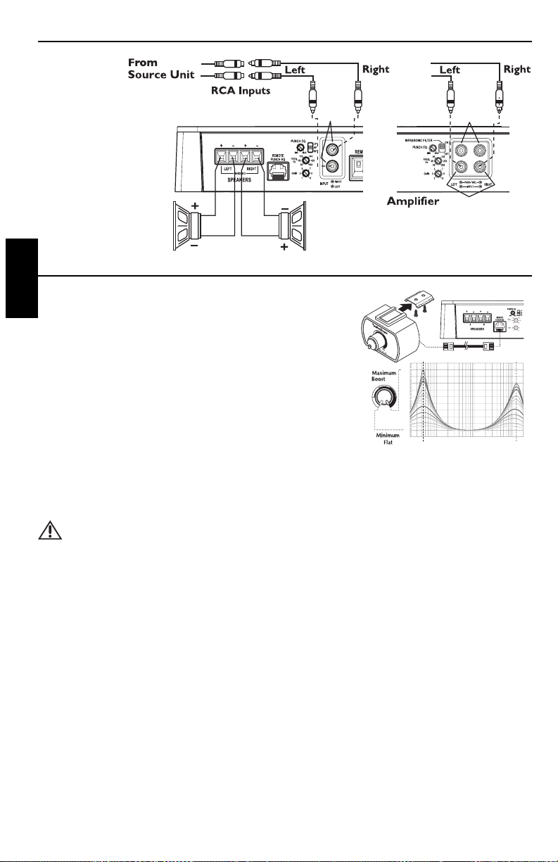
INPUT
P300-2
P200-2 P400-2
P500-2
INPUT
PASS-THRU
OR
8
Deutsch
BETRIEB
PUNCH EQ
Dies funktioniert gemeinsam mit dem Crossover-Schalter am Verstärker.
Bei Einstellung auf Tiefpassbetrieb (LP) handelt es sich um eine variable Verstärkung der Bässe.
Bei Einstellung auf Hochpassbetrieb (HP) handelt es sich um eine variable Verstärkung der Mitten und Höhen.
Bei Einstellung auf Allpassbetrieb (AP) werden sowohl die Bässe als auch die Höhen verstärkt.
Nehmen Sie Ihre persönliche Einstellung während des Zuhörens vor.
HINWEIS: Durch Anschließen der wahlweisen Punch-EQ-Fernbedienung wird der Punch-EQ am
Verstärker aufgehoben.
CROSSOVER-FREQUENZ EINSTELLEN
Zur Wahl des Hochpassmodus den Schalter am Verstärker in die HP-Position bringen. Dadurch werden Frequenzen
oberhalb des Grenzpunkts durchgelassen (kann zwischen 50 und 500 Hz eingestellt werden).
Zur Wahl des Allpassmodus den Schalter am Verstärker in die AP-Position bringen. Dadurch wird eine Anpassung des
Crossovers verhindert und alle Frequenzen werden durchgelassen.
Zur Wahl des Niedrigpassmodus den Schalter am Verstärker in die LP-Position bringen. Dadurch werden Frequenzen
unterhalb des Grenzpunkts durchgelassen (kann zwischen 50 und 500 Hz eingestellt werden).
Den Crossover-Regler vollständig abdrehen.Während das System spielt, den Crossover-Regler langsam aufdrehen, bis der
gewünschte Crossover-Punkt erreicht ist.
Zweikanalverkabelung
EINBAU
PUNCH-EQ-FERNBEDIENUNG (wahlweise)
HINWEIS: Vor 2007 hergestellte Modelle der Punch-Bass- und
Para-Punch-Fernbedienungen können nicht mit diesen
Verstärkern benutzt werden.
HINWEIS: Die der Fernbedienung beiliegende Bedienungsanleitung
beschreibt verschiedene Einbaumöglichkeiten.Wählen Sie
diejenige, die Ihren Anforderungen entspricht.
Bringen Sie Schnell An
1. Die Befestigungsklemme mithilfe der beiliegenden Schrauben einbauen.
2. Die Fernbedienung in die Befestigungsklemme einschieben, bis sie an
ihrem Platz einrastet.
3. Verlegen Sie das Kabel,schließen Sie an Fernbedienung und Verstärker an.
Funktion
4. Funktioniert genauso wie der unten beschriebene Punch-EQ.
HINWEIS: Durch Anschließen der wahlweisen Punch-EQ-Fernbedienung wird der Punch-EQ am Verstärker
aufgehoben.
VORSICHT: Übermäßige Auslenkung und nachfolgender Schaden können bei hohen Boost-Pegeln
entstehen.
dB
+20
-2
-0
+2
+4
+6
+8
+10
+12
+14
+16
+18
20 20k50 100 200 500 1k 2k 5k 10k
Hz
Bass Treble

9
FEHLERBESEITIGUNG
HINWEIS: Falls Sie nach dem Einbau Probleme haben, befolgen Sie die nachfolgenden Verfahren zur Fehlerbeseitigung:
Verfahren 1:Den Verstärker auf ordnungsgemäße Anschlüsse überprüfen.
Prüfen, ob die BETRIEBS-LED aufleuchtet. Leuchtet die BETRIEBS-LED auf,bei Schritt 3 weitermachen, falls nicht,
hier weitermachen.
1. Die Sicherung auf dem positiven Batteriekabel überprüfen und nach Bedarf ersetzen.
2. Die Sicherung(en) am Verstärker überprüfen und nach Bedarf ersetzen.
3. Überprüfen,ob der Erdungsanschluss an blankem Metall am Fahrgestell des Fahrzeugs angeschlossen ist.Nach Bedarf reparieren
oder ersetzen.
4. Überprüfen,ob an der positiven Batterie und am Fernbedienungseinschaltkabel 9 bis 16 Volt anliegen.Die Qualität der
Anschlüsse für beide Kabel am Verstärker, Stereosystem und Batterie- bzw.Sicherungshalter überprüfen. Nach Bedarf reparieren
oder ersetzen.
Verfahren 2:Schutz- oder Thermallicht leuchtet auf.
1. Falls das Schutzlicht aufleuchtet,bedeutet dies,dass möglicherweise ein Kurzschluss in den Lautsprecheranschlüssen
vorliegt.Überprüfen, ob die Lautsprecher ordernungsgemäß angeschlossen sind.Einen Widerstandsmesser benutzen, um
auf mögliche Kurzschlüsse in der Lautsprecherverkabelung zu prüfen.Eine zu niedrige Lautsprecherimpedanz kann
ebenfalls dazu führen,dass das Schutzlicht aufleuchtet.
2. Leuchtet die Thermal-LED auf, die Lautsprecherimpendanz überprüfen und gfs.neu verkabeln. Dies kann auch ein
Zeichen dafür sein, dass der Verstärker auf sehr hoher Leistung gefahren wird,ohne dass adäquater Luftstrom um den
Verstärker herum vorhanden ist.Das System ausschalten und den Verstärker abkühlen lassen. Überprüfen, ob das
Ladesystem des Fahrzeugs die erforderliche Spannung aufrechterhält.Sollte keiner dieser Schritte Abhilfe schaffen, ist der
Verstärker möglicherweise defekt.Rufen Sie dann den Kundendienst an.
Verfahren 3:Den Verstärker auf Audioleistung überprüfen.
1. Gewährleisten Sie,dass gute RCA-Eingangsanschlüsse am Stereosystem und Verstärker vorliegen.Die gesamte Länge der
Kabel auf Knicke,Spleiße usw.überprüfen.Die RCA-Eingänge bei eingeschaltetem Stereosystem auf Wechselspannung
überprüfen.Nach Bedarf reparieren bzw.ersetzen.
2. Den RCA-Eingang vom Verstärker entfernen. Den RCA-Eingang vom Prüf-Stereosystem direkt an den Verstärkereingang
anschließen.
Verfahren 4:Prüfen, ob beim Anstellen des Verstärkers ein Knacken auftritt.
1. Das Eingangssignal zum Verstärker entfernen und den Verstärker ein- und ausschalten.
2. Ist das Geräusch eliminiert, die FERNBEDIENUNGS-Ader des Verstärkers mit einem Verzögerungseinschaltmodul am
Source-Gerät anschließen.
ODER
1. Eine andere 12 V Quelle für die FERNBEDIENUNGS-Ader des Verstärkers (z.B.Batterie direkt) verwenden.
2. Falls das Geräusch elimiert ist, ein Relais zur Isolierung des Verstärkers von Anschaltgeräuschen verwenden.
Verfahren 5:Den Verstärker auf übermäßige Motorengeräusche prüfen.
1. Alle signalübertragenden Kabel (RCA-, Lautsprecherkabel) von Strom- und Erdungskabeln entfernt verlegen.
ODER
BETRIEB
LAUTSTÄRKE (GAIN) EINSTELLEN
Zur Einstellung der Lautstärke die Lautstärkeregler des Verstärkers ganz nach unten
stellen (nach links drehen). Die Lautstärke des Source-Geräts erhöhen, bis eine
Verzerrung hörbar ist, dann ein wenig verringern, bis die Verzerrung nicht mehr hörbar
ist.An den meisten Source-Geräten bedeutet dies ganz nach oben.Als Nächstes die
Lautstärkeeinstellung des Verstärkers erhöhen, bis eine adäquate Lautstärke erreicht ist.
HINWEIS: Der beste Rauschabstand und Dynamikbereich werden bei einer auf das
Minimum gestellten Lautstärke erreicht.Die meisten Benutzer finden,dass
adäquate Lautstärke etwa in der Mitte des Einstellungsbereichs erzielt wird.
VORSICHT: Vermeiden Sie, die Verstärkerlautstärke sehr hoch
einzustellen, da Geräusche und Verzerrung sich dadurch
wesentlich erhöhen.
HINWEIS: Kontaktieren Sie den technischen Kundendienst von Rockford für genauere Einstellungsverfahren.
Crossover Switch
Crossover-Schalter

10
Deutsch
Die technischen Daten können sich ohne Ankündigung ändern.
TECHNISCHE DATEN
MODELL- Punch P200-2 P300-2 P400-2 P500-2
Kontinuierliche Nennleistung (Mittelwert) - Bei 14,4 Batterie-Volt gemessen
4 -Belastung pro Kanal 50 Watt x 2 75 Watt x 2 100 Watt x 2 125 Watt x 2
2 -Belastung pro Kanal 100 Watt x 2 150 Watt x 2 200 Watt x 2 250 Watt x 2
4 -Belastung überbrückt 200 Watt x 1 300 Watt x 1 400 Watt x 1 500 Watt x 1
Maße: Höhe 5,71 cm 5,71 cm 5,71 cm 5,71 cm
Breite 19,37 cm 19,37 cm 19,37 cm 19,37 cm
Länge 22,80 cm 22,80 cm 26,03 cm 33,07 cm
Bemessungsstrom der Batteriesicherung 40A 50A 80A 100A
(Amp) Extern (Liegt nicht bei)
A-gewichteter Rauschabstand
Referenzwert bei 1 W an 4 Ohm ≥85 dB
A-gewichteter Rauschabstand
Referenzwert bei Nennstromwert an 4 Ohm ≥105 dB
Crossoversteilheit 12 dB/Oktav Butterworth
Crossoverfrequenz von 50 bis 500 Hz variabel
Frequenzverhalten 20 Hz bis 20 kHz ±1 dB
Einstellbarer Signalspannungsbereich Von 150 mV bis 5 V variabel (RCA-Eingang)
Schutz NOMAD - Interne Analog-Computer-Ausgangsschutzschaltung
beschränkt Stromzufuhr im Überlastungsfall und bietet
Schutz vor Kurzschlüssen.Thermaler Schalter schaltet
den Verstärker im Überhitzungsfall ab.
Entzerrung PEQ (Punch-Entzerrung) Von 0 dB bis +18 dB bei 45 Hz und/oder
0 dB bis +12 dB bei 12 kHz variable
Eingangsimpedanz 20 K Ohm
Betriebsspannung 9 bis 16 V DC
Symmetrische Eingänge Ja
CMRR (Gleichtaktunterdrückungsverhältnis) >55 dB @ 1kHz
Dämpfungsfaktor >200
THD+N (Gesamtklirrfaktor + Geräusch) <0,1 bei 2 Ohm und <0,05 bei 4 Ohm
Diese technischen Daten sind Amplifier Power Standard CEA-2006 normkonform
FEHLERBESEITIGUNG
2. Alle elektrischen Komponenten zwischen der Stereoanlage und dem/den Verstärker(n) umgehen. Die Stereoanlage direkt am
Verstärkereingang anschließen. Falls das Geräusch eliminiert ist, ist das umgangene Gerät die Ursache des Geräuschs.
ODER
3. Die vorhandenen Erdungskabel aller elektrischen Komponenten entfernen.Die Kabel an anderen Stellen wieder erden. Prüfen,
ob die Erdungsstelle sauberes,glänzendes Metall ist,das frei von Farbe,Rost usw.ist.
ORER
4. Ein zweites Erdungskabel vom Negativpol der Batterie zum Fahrgestellsmetall oder Motorblock des Fahrzeugs hinzufügen.
ODER
5. Die Drehstromlichtmaschine und Batterieladung von ihrem Mechaniker prüfen lassen. Die ordnungsgemäße Funktion des
elektrischen Systems am Fahrzeug prüfen,und zwar einschließlich des Verteilers, der Zündkerzen,der Zündkerzenkabel, des
Spannungsreglers usw.

11
INFORMATIONEN ZUR BESCHRÄNKTEN GARANTIE
Rockford Corporation bietet für Rockford Fosgate Produkte eine beschränkte Garantie zu folgenden
Bedingungen:
Laufzeit der Garantie
Source-Geräte, Lautsprecher, Signalprozessoren und PUNCH-Verstärker – 1 Jahr
POWER-Verstärker – 2 Jahre
Alle werkseitig aufgearbeiteten Produkte – 90 Tage (Quittung erforderlich)
Was gedeckt ist
Diese Garantie erstreckt sich nur auf Rockford Fosgate Produkte, die von Rockford Fosgates
Vertragshändlern an Verbraucher in den Vereinigten Staaten von Amerika oder deren Besitzungen
verkauft wurden. Produkte, die von Rockford Fosgates Vertragshändlern an Verbraucher in einem
anderen Land verkauft wurden,sind nur durch den Händler in dem betreffenden Land,nicht jedoch
durch die Rockford Corporation gedeckt.
Wer ist gedeckt
Diese Garantie deckt nur den ursprünglichen Käufer von Rockford Produkten, die von einem Rockford
Fosgate Vertragshändler in den Vereinigten Staaten gekauft wurden. Um Leistungen in Anspruch zu
nehmen, muss der Käufer Rockford eine Kopie der Quittung vorlegen,die den Kundennamen, den
Händlernamen, das Produkt und das Kaufdatum angibt.
Produkte, die sich während der Garantiezeit als defekt erweisen, werden nach Rockford Fosgates
Ermessen repariert oder (mit einem Produkt, das als gleichwertig erachtet wird,) ersetzt.
Was nicht gedeckt ist
1. Durch Unfall, Missbrauch,unsachgemäßen Betrieb,Wasser, Diebstahl oder Versand verursachte Schäden
2. Jegliche Kosten, die im Zusammenhang mit Ein- bzw.Ausbau des Produkts entstanden sind
3. Leistungen, die nicht von Rockford oder einem autorisierten Rockford Fosgate Servicecenter erbracht
wurden
4. Produkte, an denen die Seriennummer unkenntlich gemacht, verändert oder entfernt wurde
5. Folgeschäden an anderen Komponenten
6. Produkte, die außerhalb der USA gekauft wurden
7. Produkte, die nicht von einem Rockford Fosgate Vertragshändler gekauft wurden
Einschränkung von implizierten Garantien
Implizierte Garantien, einschließlich von Garantien der Eignung für einen bestimmten Zweck und
Marktgängigkeit, werden auf den Zeitraum der obenstehenden ausdrücklichen Garantie beschränkt.
Manche Staaten erlauben Einschränkungen der Gültigkeit der implizierten Garantie nicht. Daher trifft
diese Einschränkung nicht in allen Fällen zu.
Inanspruchnahme des Kundendienstes
Kontaktieren Sie bitte den Rockford Fosgate Vertragshändler, bei dem Sie dieses Produkt gekauft haben.
Benötigen Sie zusätzliche Hilfe, rufen Sie den Kundendienst von Rockford unter 1-800-669-9899 an.Sie
erhalten dann eine RA# (Rücksendungsautorisierungsnummer), um jegliche Produkte an Rockford Fosgate
zurückzusenden. Sie sind für die Rücksendung des Produkts an Rockford verantwortlich.
EU-Garantie
Dieses Produkt entspricht den gültigen EU-Garantiebestimmungen. Sprechen Sie mit Ihrem
Vertragshändler über die Einzelheiten.

2
Italiano
INTRODUZIONE
INDICE
Egregio cliente,
Congratulazioni per aver acquistato la miglior marca di amplificatori per auto a livello mondiale.Alla Rockford Fosgate, siamo
fanatici per quanto riguarda la miglior riproduzione musicale e siamo compiaciuti che abbiate scelto il nostro prodotto. Dopo
anni di competenza ingegneristica, maestria manuale e procedure di prova critica, abbiamo creato una larga gamma di
prodotti che riproducono la musica con la limpidezza e la pienezza che vi meritate.
Per ottenere le massime prestazioni vi consigliamo di far installare il vostro nuovo prodotto Rockford Fosgate da un rivenditore
autorizzato, in quanto noi forniamo un addestramento specializzato ai nostri tecnici attraverso il Rockford Fosgate Technical
Training Institute (RTTI).Vi preghiamo di leggere con cura i termini della garanzia e di serbare sia la ricevuta che l’imballaggio
originale per qualsiasi evenienza futura.
Un prodotto superiore ed un’installazione competente rappresentano soltanto una parte del quadro generale quando si tratta
del vostro sistema audio. Dovrete assicurarvi che il vostro installatore abbia utilizzato accessori da installazione della Rockford
Fosgate, autentici al 100%. La Rockford Fosgate ha proprio tutto—da cavi e fili RCA per altoparlanti a connettori Power di
linea e di batterie. Insistete! Dopo tutto,il vostro nuovo sistema audio si merita solo il meglio.
Per aggiungere poi il tocco finale alla vostra nuova immagine da Rockford Fosgate, dovrete ordinare gli accessori Rockford, che
comprendono di tutto—dalle magliette e le giacche ai cappelli e gli occhiali da sole.
Per ottenere un opuscolo gratuito illustrante i prodotti della Rockford Fosgate nonché gli accessori,
visitate il nostro sito: www.rockfordfosgate.com
oppure, negli USA, chiamare il numero 1-800-669-9899 o il FAX 1-800-398-3985.
Da tutti gli altri paesi, telefonare al numero +001-480-967-3565 oppure inviare una fax al numero +001-480-967-8132.
OSSERVATE LE REGOLE DEL “SUONO SENZA PERICOLI”
La costante esposizione a livelli di pressione acustica al di sopra dei 100dB possono causare la
perdita permanente dell’udito. I sistemi audio ad alta potenza possono produrre livelli di pressione
acustica ben superiori ai 130dB. Si consiglia il buon senso e l’osservanza delle regole del “suono
senza pericoli”
NOTA: Ripassare ciascuna sezione per ulteriori
ragguagli.
Se dopo aver letto il vostro manuale, aveste ancora delle domande al riguardo del vostro prodotto, vi
preghiamo di consultare il vostro rivenditore Rockford Fosgate. Se necessitaste di qualsiasi assistenza
ulteriore, potrete telefonarci direttamente al numero 1-800-669-9899.Vi chiederemo di fornire il vostro
numero di serie, numero di modello, e la data d’acquisto.
Il numero di serie è ubicato sull’esterno della scatola.Vi preghiamo di annotarlo in modo permanente nello
spazio fornito di sotto. Questo numero vi servirà da verifica nei confronti della vostra garanzia di fabbrica
e potrebbe rivelarsi utile nel recupero della vostra unità di fonte se mai venisse rubata.
Numero di serie: ____________________________________
Numero di modello: _________________________________
Introduzione . . . . . . . . . . . . . . . . . . . . . . . . 2
Istruzioni di sicurezza . . . . . . . . . . . . . . . . . 3
Caratteristiche del design . . . . . . . . . . . . 4-5
Installazione . . . . . . . . . . . . . . . . . . . . . . . 5-8
Considerazioni sull’installazione . . . . . . . . . . 5
Posizionamento . . . . . . . . . . . . . . . . . . . . . . 5
Batteria e caricamento . . . . . . . . . . . . . . . . . 6
Cablaggio del sistema . . . . . . . . . . . . . . . . . . 6
Funzionamento . . . . . . . . . . . . . . . . . . . . 8-9
Equalizzatore Punch a distanza (opzionale) . 8
Equalizzatore Punch. . . . . . . . . . . . . . . . . . . . 8
Regolazione della frequenza di incrocio . . . 8
Regolazione del guadagno . . . . . . . . . . . . . . . 9
IIndividuazione/riparazione guasti . . . . 9-10
Specifiche . . . . . . . . . . . . . . . . . . . . . . . . . . 10
Informazioni inerenti alla garanzia
limitata. . . . . . . . . . . . . . . . . . . . . . . . . . . . 11
2008 Rockford Corporation.Tutti i diritti riservati.
Rockford Fosgate, il logo Rockford Fosgate, il logo POWER e il logo PUNCH sono marchi
di fabbrica depositati o marchi di fabbrica di Rockford Corporation.

3
CONTENUTO DELL’IMBALLAGGIO
PRIMI PASSI
Benvenuti alla Rockford Fosgate! Questo manuale è stato concepito per fornire ragguagli al proprietario, al
rivenditore e all’installatore. Per coloro che desiderano informazioni rapide circa l’installazione di questo
prodotto, vi preghiamo di consultare la sezione Installazione di questo manuale. Altri ragguagli sono
disponibili attraverso l’Indice. Alla Rockford Fosgate, abbiamo fatto di tutto per assicurarci che tutte le
informazioni contenute in questo manuale fossero d’uso corrente. Pertanto, dato che siamo sempre alla
ricerca di nuovi modi per migliorare i nostri prodotti, tali informazioni sono soggette a modifiche senza
preavviso.
Vi preghiamo di visitare il nostro sito internet per le più recenti informazioni su tutti i
prodotti Rockford.
www.rockfordfosgate.com
Il kit per gli attrezzi compreso con ciascun amplificatore contiene tutti gli attrezzi da montaggio necessari
per fissare l’amplificatore al veicolo.
ISTRUZIONI DI SICUREZZA
Questo simbolo con la dicitura “AVVERTIMENTO” intende
avvertire l’utente alla presenza di istruzioni importanti. La mancata
osservanza di queste istruzioni potrebbe causare gravi lesioni personali
o persino la morte.
Questo simbolo con la dicitura “ATTENZIONE” intende avvertire
l’utente alla presenza di istruzioni importanti. La mancata osservanza di
queste istruzioni potrebbe causare gravi lesioni personali o danni
all’unità.
ATTENZIONE: Per evitare lesioni personali e danni all’unità, vi preghiamo di leggere e seguire le
istruzioni in questo manuale. Desideriamo che questo sistema audio vi procuri
soddisfazione, non un mal di capo.
ATTENZIONE: Se aveste dei dubbi circa l’installazione, rivolgetevi ad un tecnico qualificato della
Rockford Fosgate.
ATTENZIONE: Prima dell’installazione, scollegate il terminale negativo (-) della batteria per evitare
danni all’unità, pericoli d’incendio e/o potenziali lesioni personali.
Modello P200-2, P300-2, P400-2 o P500-2
Amplificatore di potenza a 2 canali
Manuale di installazione e funzionamento
Kit per gli attrezzi da montaggio

4
Italiano
CARATTERISTICHE DEL DESIGN
1. LED alimentazione (parte superiore dell'unità - non indicato) – Questo LED blu si accende quando
l'unità viene accesa.
2. LED termico (sulla parte superiore dell'unità, non mostrato) - questo LED rosso si accende per
indicare che è scattata la protezione da surriscaldamento perché gli elementi interni dell'amplificatore si sono
surriscaldati. Quando ciò si verifica l'amplificatore si spegne e rimane spento finché non si è raffreddato.
3. LED di protezione (parte superiore dell'unità - non indicato) – Questo LED giallo si accende se
viene rilevato un corto circuito o un'impedenza troppo bassa ai collegamenti con i diffusori.In tal caso,
l'amplificatore si spegne automaticamente.
4. Dissipatore di calore in alluminio fuso – Il dissipatore di calore in alluminio fuso dell’amplificatore Punch
dissipa il calore generato dalla circuiteria dell’amplificatore.
5. Terminali degli altoparlanti – I connettori tipo morsetto placcati in nichel (+ e -) sono in grado di
accettare conduttori di diametro compreso tra 8 e 18 AWG.
6. Remote Punch EQ (comando equalizzatore Punch a distanza opzionale) - il collegamento del
Remote Punch Bass si effettua tramite cavo RJ-45 e può essere eseguito in modi diversi per facilitare
l'accesso al comando. Il commando serve a elevare le informazioni di bassa e/o alta frequenza per sopraffare
il rumore della strada Quando è collegato,il comando a distanza sostituisce l'equalizzatore Punch
sull'amplificatore.
NOTA: i vecchi comandi a distanza Punch Bass e Para-Bass (quelli prima del 2007) non funzioneranno
con questi amplificatori.
7. Equalizzatore Punch - un equalizzatore Punch basato su gyrator che elimina lo spostamento di frequenza
con l'aumento. Questo funziona assieme all'interruttore di crossover sull'amplificatore.Quando è impostato
su operazione Low-Pass (LP), questo rappresenta un valore variabile di aumento dei bassi. Quando è
impostato su operazione High-Pass (HP), questo rappresenta un valore variabile di aumento dei bassi
intermedi e dei toni acuti. Quando è impostato su operazione All Pass (AP), sia le frequenze dei bassi che
quelle dei toni acuti sono aumentate.
8. Interruttore di crossover - interruttore selezionabile per funzionamento High-Pass (HP), passa-alto,All
Pass (AP), passa-tutto, o Low-Pass (LP),passa-basso.
9. Frequenza di incrocio variabile – Gli amplificatori hanno un filtro Butterworth incorporato da
12dB/ottava con un punto di incrocio variabile dai 50Hz ai 500Hz.
10. Comando del guadagno – Il comando del guadagno d’ingresso è stato preregolato per essere conforme
con l’uscita della maggiore parte delle unità di fonte. Può essere regolato in modo da conformarsi ai livelli di
uscita provenienti da una varietà di unità di fonte.
4578
9610
13 14
P400-2
11
12
4578
9610
13 14
P500-2
11
12
4578
9610
13 14
P200-2
P300-2
12

5
CARATTERISTICHE DEL DESIGN
INSTALLAZIONE
CONSIDERAZIONI SULL’INSTALLAZIONE
Segue un elenco degli utensili necessari per eseguire l’installazione:
Portafusibile e fusibile.
(Per informazioni sulla portata dei fusibili,
consultare le specifiche.)
Voltmetro/ohmetro
Pinze spelafili
Pinze raggrinzafili
Pinze tagliafili
Cacciavite a croce no.2
Chiave per morsetto batteria
Trapano e punte assortite
Guaina termoretraibile avente un diametro di 0,32 cm
Connettori vari
Lunghezza adeguata—Filo di tensione rosso
Lunghezza adeguata—Filo di accensione a telecomando
Lunghezza adeguata—Filo di massa nero
NOTA:Per il collegamento di alimentazione (B+) e massa (GND) consigliamo di usare conduttori di
misura 4 AWG.
Questa sezione si concentra su alcune considerazioni a livello di veicolo inerenti all’installazione del vostro nuovo
amplificatore.Programmando a priori la configurazione del vostro sistema audio nonché i migliori cablaggi,risparmierete
tempo durante l’installazione. Quando avrete deciso la miglior configurazione per il vostro nuovo sistema audio,
assicuratevi di poter accedere facilmente a ciascuna componente per effettuare le regolazioni necessarie.
ATTENZIONE: Se aveste dei dubbi circa l’installazione, rivolgetevi ad un tecnico qualificato Rockford
Fosgate.
ATTENZIONE: Prima dell’installazione,scollegate il terminale negativo (-) della batteria per evitare
danni all’unità, pericoli d’incendio e/o potenziali lesioni personali.
Prima di iniziare qualsiasi operazione d’installazione, vi consigliamo di seguire queste semplici regole:
1. Assicuratevi di aver letto tutte le istruzioni con cura e di averle capite prima di effettuare qualsiasi tentativo d’installazione
nei confronti dell’unità.
2. Per motivi di sicurezza,scollegate il cavo negativo dalla batteria prima di dare l’avvìo all’installazione.
3. Per facilitare l’installazione,vi consigliamo di far scorrere tutti i cavi prima di montare la vostra unità di fonte nell’ubicazione
desiderata.
4. Fate passare tutti i cavi RCA vicini l’uno all’altro ma lontano da fili ad alta tensione.
5. Usate connettori di alta qualità per garantire un’installazione che dà affidamento e per ridurre al minimo la perdita di segnali
o di potenza.
6. State attenti prima di trapanare! Cercate di non trapanare e di non tagliare i serbatoi della benzina; le condutture del
carburante, dei freni, del sistema idraulico e a depressione;nonché i fili elettrici quando state lavorando su qualsiasi veicolo.
7. Non fate mai scorrere i fili sotto il veicolo.Avrete la protezione migliore faccendo scorrere i fili all’interno del veicolo.
8. Evitate di far scorrere i fili sopra o attraverso delle estremità affilate. Usate guarnizioni di tenuta in gomma o in plastica per
proteggere qualsiasi filo che passi attraverso del metallo, soprattutto il parafiamma.
9. Proteggete SEMPRE sia la batteria che il sistema elettrico usando fusibili adatti.Installate sia un fusibile che un portafusibili
adeguati sul filo a tensione da +12V entro 45,7 cm.dal terminale della batteria.
10. Quando eseguite la messa a terra del telaio del veicolo, raschiate tutta la vernice dal metallo per assicurarvi un
collegamento a terra pulito e saldo.I collegamenti a terra dovrebbero essere più corti possibile e sempre a contatto di
metallo che sia saldato all’autotelaio del veicolo.
11. Spinotti passa-attraverso RCA – Il passa-attraverso fornisce una fonte conveniente per concatenare a
margherita un amplificatore supplementare senza far scorrere un altro paio di cavi RCA dalla parte anteriore
del veicolo all’ubicazione posteriore dell’amplificatore.
12. Spinotti d’ingresso RCA – Gli spinotti RCA standard di fabbrica forniscono un collegamento facile per
l’ingresso del livello di segnale. Sono placcati in nichel per prevenire le alterazioni del segnale causate dalla
corrosione.
13. Terminale REM – Questo connettore robusto a morsetto placcato in nickel è in grado di accettare
conduttori di diametro compreso tra 12 AWG e 24 AWG.Questo terminale viene utilizzato per accendere
o spegnere l'amplificatore a quando viene alimentato con +12V c.c.
14. Terminali di potenza – I connettori a morsetto di alimentazione e di massa sono placcati in nickel e sono
in grado di accettare conduttori di diametro fino a 4 AWG.
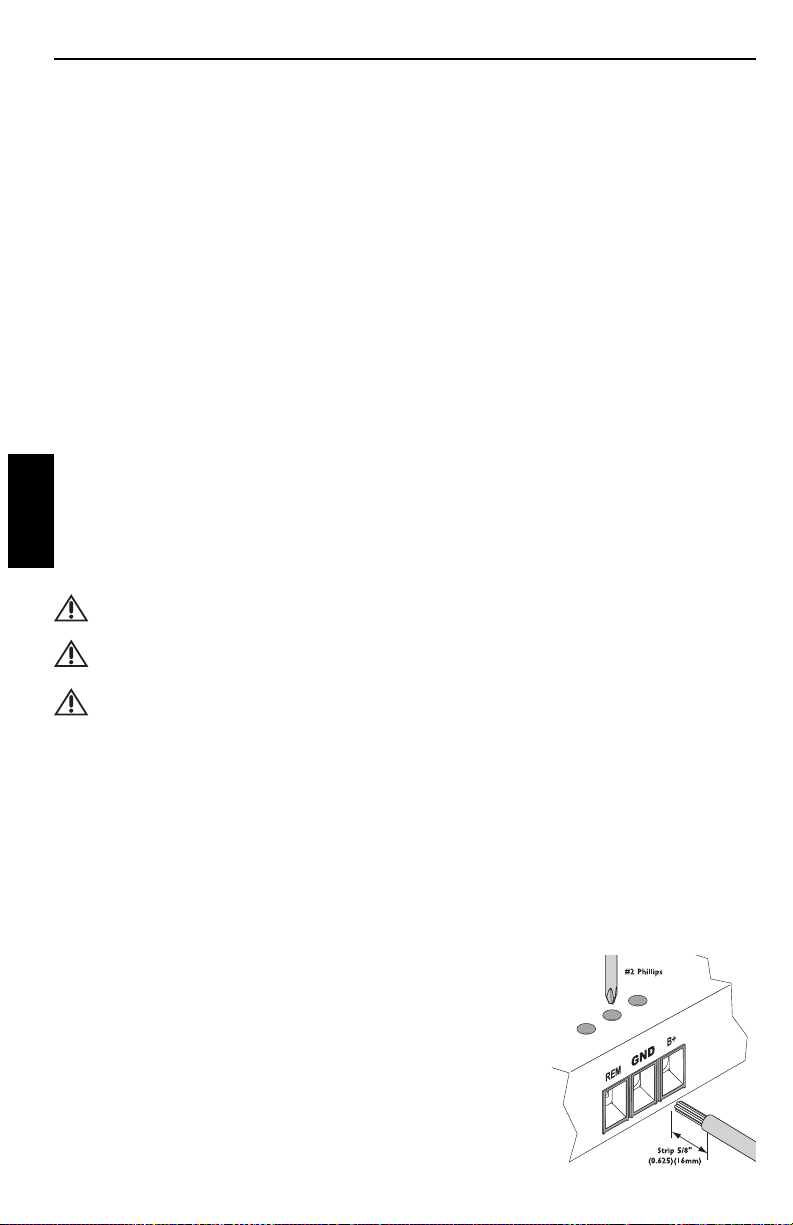
6
Italiano
INSTALLAZIONE
BATTERIA E CARICAMENTO
Gli amplificatori rappresentano un ulteriore carico sulla batteria e sul sistema di caricamento del veicolo. Si
consiglia di controllare la condizione dell'alternatore e della batteria per assicurarsi che il sistema elettrico
sia in grado di far fronte al carico aggiuntivo dovuto al sistema stereofonico. I sistemi elettrici standard in
buone condizioni dovrebbero poter far fronte al carico supplementare di qualsiasi amplificatore della serie
Punch senza alcun problema, sebbene la vita della batteria nonché quella dell’alternatore potrebbero
ridursi leggermente. Per sfruttare al massimo le prestazioni del vostro amplificatore, vi consigliamo di
utilizzare una batteria robusta ed un condensatore ad accumulazione di energia.
CABLAGGIO DEL SISTEMA
ATTENZIONE: Se aveste dei dubbi circa l’installazione, rivolgetevi ad un tecnico qualificato della
Rockford Fosgate.
ATTENZIONE: Prima dell’installazione, scollegate il terminale negativo (-) della batteria per evitare
danni all’unità, pericoli d’incendio e/o potenziali lesioni personali.
ATTENZIONE: Evitate di far scorrere i fili elettrici vicino ai cavi d’entrata a basso livello,alle
antenne, ai cavi di tensione, ad attrezzature sensibili o a cablaggi preassemblati. I fili
elettrici portano una tensione notevole e potrebbero indurre rumori dentro il
sistema audio.
1. Programmate il cablaggio dei fili.Tenete i fili RCA insieme ma isolati dai cavi a tensione dell’amplificatore e da
qualsiasi accessorio auto ad alta tensione, soprattutto i motori elettrici.Ciò è necessario per evitare che il rumore
proveniente da campi elettrici irradiati possa accoppiarsi con il segnale audio. Quando fate scorrere i fili attraverso il
parafiamma o attraverso qualsiasi barriera metallica,proteggeteli con delle guarnizioni di tenuta in gomma o in
plastica per evitare i cortocircuiti. Lasciate i fili piuttosto lunghi a questo punto; più tardi potrete regolare la loro
lunghezza in modo più preciso.
NOTA:Per il collegamento di alimentazione (B+) e massa (GND) consigliamo di usare conduttori di
misura 4 AWG.
2. Preparare il filo ROSSO (cavo di alimentazione) per il collegamento all’amplificatore, rimuovendo circa 13 mm di
isolante dall'estremità del filo.Inserire la parte scoperta del cavo nel terminale B+ e stringere la vite di arresto per
fissarlo in posizione.
NOTA:Il cavo B+ DEVE avere un fusibile a non più di 45,7 cm dalla
batteria del veicolo. Installare il portafusibili sotto il cofano e
verificare che i collegamenti siano a tenuta stagna.
3. Tagliare il cavo ROSSO (alimentazione) entro 45,7 cm dall'amplificatore e
inserire un portafusibili in linea. Per informazioni sulla portata dei fusibili da
usare, consultare il capitolo Specifiche. NON installare il fusibile a questo
punto.
4. Spelate via 1,27 cm dall’estremità batteria del cavo a tensione e raggrinzite un
grosso terminale ad anello contro il cavo. Usate il terminale ad anello per
effettuare un collegamento al terminale positivo della batteria.NON
installate ancora il fusibile.
POSIZIONAMENTO
Scompartimento del motore
Non montate mai questa unità nello scompartimento del motore. Ciò annullerà la vostra garanzia.
Montaggio nel bagagliaio
Il montaggio dell'amplificatore in posizione verticale o invertita sarà sufficiente a fornire adeguato raffreddamento all'unità.
Se l'amplificatore viene montato sul fondo del bagagliaio,si ottiene il migliore raffreddamento dell'unità.
Montaggio nello scampartimento passeggeri
Se montate l’amplificatore nell’abitacolo,esso funzionerà finché possiate fornire una quantità sufficiente di aria per
permettere all’amplificatore di raffreddarsi.Se avete intenzione di montare l’amplificatore sotto il sedile del veicolo,dovete
lasciare un vuoto d’aria di almeno 2,54 cm attorno al dissipatore di calore dell’amplificatore.
Se montate l’amplificatore nell’abitacolo,lasciando un vuoto d’aria meno di 2,54 cm attorno al suo dissipatore di calore,
non otterrete il raffreddamento necessario e ciò comprometterà notevolmente la prestazioni dell’amplificatore. Pertanto,
non è assolutamente raccommandabile.

INPUT
P300-2
P400-2
P500-2
INPUT
PASS-THRU
OR
P200-2
7
INSTALLAZIONE
5. Preparate il filo NERO (cavo della messa a terra) per poterlo attaccare all’amplificatore, spelando via 13 mm di
isolante dall’estremità del filo.Inserite il filo spelato dentro il terminale GND e stringete la vite di arresto per fissare
il cavo.Preparate la messa a terra del telaio raschiando via la vernice dalla superficie metallica e pulitela
accuratamente, rimovendo ogni traccia di lubrificazione e di sudiciume. Spelate l’altra estremità del filo e attaccategli
un serrafili ad anello. Fissate il cavo al telaio usando una vite non anodizzata e una rondella a stella.
NOTA:Far in modo che il cavo NERO (Massa) sia il più corto possibile. Sempre meno di 76 cm.
6. Preparare il cavo di accensione REM per il collegamento all’amplificatore, rimuovendo circa 13 mm di isolante
dall'estremità del filo.Inserire la parte scoperta del cavo nel terminale REM e stringere la vite di arresto per fissarlo
in posizione. Collegare l'altro estremo del cavo REM a una fonte positiva commutata a 12 Volt.La tensione
commutata proviene generalmente cavo dell'accensione remota dell'amplificatore dell’unità di fonte. Qualora l'unità
sorgente non avesse tali uscite disponibili,la soluzione consigliata consiste nel cablare un commutatore meccanico in
linea con una fonte da 12 volt per attivare l’amplificatore.
7. Montate l’amplificatore saldamente al veicolo o all’apposita struttura di supporto.Assicuratevi di non montare
l’amplificatore su pannelli di plastica o di cartone in quanto ciò potrebbe permettere alle viti di allentarsi e di
fuoriuscire dal pannello durante le vibrazioni stradali o se il veicolo dovesse arrestarsi improvvisamente.
8. Collegate il segnale di fonte inserendo i cavi RCA negli spinotti d’ingresso ubicati sull’amplificatore stesso.
ATTENZIONE: Verificare sempre che l'alimentazione sia spenta o scollegata presso
l'amplificatore prima di collegare cavi RCA. In caso contrario si
potrebbero causare lesioni, danni all'amplificatore o ai componenti
collegati.
9. Collegate gli altoparlanti. Spelate i fili degli altoparlanti di 1,27 cm e inseriteli nel terminale degli altoparlanti,
stringendo la vite di arresto per fissarli.Assicuratevi di mantenere la corretta polarità per gli altoparlanti. NON
collegate a massa nessuno dei cavi dell’amplificatore in quanto ciò potrebbe dar luogo ad un funzionamento
instabile.
10 Eseguite un controllo finale dell’intero cablaggio del sistema per assicurarvi che tutti i collegamenti siano corretti.
Controllate tutti i collegamenti di tensione e di massa per la presenza di fili sfrangiati o di collegamenti allentati che
potrebbero dar luogo a problemi.Installare il fusibile in linea vicino al collegamento della batteria.
NOTA:Seguite i diagrammi per ottenere la corretta polarità di segnale.
Collegamento
alla tensione
Mono in
parallelo

INPUT
P300-2
P200-2 P400-2
P500-2
INPUT
PASS-THRU
OR
Italiano
8
FUNZIONAMENTO
EQUALIZZATORE PUNCH
Questo funziona assieme all'interruttore di crossover sull'amplificatore.
Quando è impostato su operazione Low-Pass (LP), questo rappresenta un valore variabile di aumento dei bassi.
Quando è impostato su operazione High-Pass (HP), questo rappresenta un valore variabile di aumento dei bassi
intermedi e dei toni acuti.
Quando è impostato su operazione All Pass (AP), sia le frequenze dei bassi che quelle dei toni acuti sono
aumentate.
Impostare il comando sul valore preferito mentre si ascolta.
NOTA: Il collegamento del equalizzotore Punch a distanza sostituisce l'equalizzatore Punch sull'amplificatore.
REGOLAZIONE DELLA FREQUENZA DI INCROCIO
Spostando l’interruttore alla posizione HP si potrà regolare l’amplificatore sul modo di frequenza passa-alto,
permettendo alle frequenze al di sopra della frequenza di taglio di passare. Regolabile tra i 50 e i 500Hz.
Spostando l’interruttore alla posizione AP si potrà regolare l’amplificatore sul modo di frequenza passa-tutto,
impedendo qualsiasi regolazione della frequenza di incrocio e permettendo a tutte le frequenze di passare.
Spostando l’interruttore alla posizione LP si potrà regolare l’amplificatore sul modo di frequenza passa-basso,
permettendo alle frequenze al di sotto della frequenza di taglio di passare. Regolabile tra i 50 e i 500Hz.
Ruotare la manopola di regolazione della frequenza di incrocio fino alla frequenza minima. Mentre il sistema audio
è in funzione, ruotare la manopola lentamente in senso contrario, finché non si raggiunga il punto d’incrocio
desiderato.
Cablaggio a 2 canali
INSTALLAZIONE
EQUALIZZATORE PUNCH A DISTANZA (opzionale)
NOTA: i vecchi comandi a distanza Punch Bass e Para-Bass (quelli prima del 2007)
non funzioneranno con questi amplificatori.
NOTA: Utilizzare le istruzioni fornite con il comando a distanza per determinare lo
schema di installazione preferito tra quelli possibili.
Rapidamente Installi
1. Usando le viti fornite, installare la graffa di montaggio.
2. Fare slittare il comando a distanza sulla graffa di montaggio fino a farlo scattare.
3. Posiziona il cavo, collegano alla comando a distanza ed all'amplificatore.
Funzionamento
4. Il funzionamento è lo stesso dell'equalizzatore Punch illustrato sotto.
NOTA: Il collegamento del equalizzotore Punch a distanza sostituisce l'equalizzatore Punch sull'amplificatore.
ATTENZIONE: A livelli elevati di intensità si potrebbe raggiungere il limite della corsa,causando danni all'unità.
dB
+20
-2
-0
+2
+4
+6
+8
+10
+12
+14
+16
+18
20 20k50 100 200 500 1k 2k 5k 10k
Hz
Bass Treble

9
INDIVIDUAZIONE/RIPARAZIONE GUASTI
NOTA: Se incontraste dei problemi dopo l’installazione, seguite le procedure per la localizzazione e la riparazione dei guasti
elencate di sotto.
Procedura 1:Controllate che l’amplificatore abbia i collegamenti adeguati.
Controllate che la spia dell’ACCENSIONE sia accesa.Se la spia di ACCENSIONE è accesa,passare al numero 3,
altrimenti continuare
1. Controllare il fusibile in linea sul cavo positivo della batteria. Sostituire,se necessario.
2. Controllare il fusibile sull'amplificatore.Sostituire,se necessario.
3. Controllate che la messa a terra sia collegata al metallo non verniciato del telaio del veicolo.Se necessario, effettuare riparazioni o
sostituzioni.
4. Controllate che ci siano dai 9 ai 16 volt di tensione al cavo positivo della batteria e al cavo di accensione del comando a distanza.
Controllate che ci siano collegamenti di qualità per entrambi i cavi con l’amplificatore,l'impianto stereofonico e la
batteria/portafusibili. Se necessario, effettuare riparazioni o sostituzioni.
Procedura 2:gli indicatori luminosi per la protezione o la temperatura sono accesi .
1. Se l'indicatore di protezione è acceso, ciò può indicare un corto circuito nel collegamento con gli altoparlanti. Controllare
che i collegamenti agli altoparlanti siano corretti e utilizzare un misuratore di resistenza per controllare che non ci siano
corto circuiti nei cavi dell'altoparlante.L'indicatore di protezione si può accendere anche in caso di impedenza
dell'altoparlante troppo bassa.
2. Se la spia termica si accende,controllare che l'impedenza dei diffusori sia corretta e modificare il cablaggio se necessario. Ciò
può anche indicare che si stanno fornendo all'amplificatore livelli di potenza molto alti senza adeguata ventilazione dell'unità
Spegnere il sistema e lasciare che l'amplificatore si raffreddi. Controllare che l'impianto di carica del veicolo mantenga la
tensione corretta.Se questi punti non correggono il problema,potrebbe esserci un guasto nell'amplificatore;per supporto,
mettersi in contatto con l'assistenza clienti.
Procedura 3:Controllare le uscite audio dell’amplificatore.
1. Controllare che sia il sistema stereofonico che l’amplificatore siano collegati correttamente all’entrata RCA.Controllare che lungo
l’intera lunghezza dei cavi non ci siano attorcigliamenti,giunture, ecc.Verificare che alle entrate RCA non si abbia corrente alternata
con il sistema stereofonico acceso.Se necessario, effettuare riparazioni o sostituzioni.
2. Scollegare l'ingresso RCA dall'amplificatore. Collegare l'ingresso RCA dal sistema stereofonico di prova direttamente all'ingresso
dell'amplificatore.
Procedura 4:Controllate l’amplificatore se si verificasse uno schiocco al momento dell’accensione.
1. Scollegate il segnale d’entrata verso l’amplificatore; spegnete e riaccendete l’amplificatore.
2. Se il rumore venisse eliminato,collegate il cavo a tensione REMOTE dell’amplificatore all’unità di fonte con un modulo di accensione
ad azione ritardata.
OPPURE
1. Usate una fonte da 12 volt diversa per il cavo a tensione REMOTE dell’amplificatore (in altri termini,direttamente dalla batteria).
2. Se il rumore venisse eliminato,usate un relé per isolare l’amplificatore da entrate ed uscite rumorose al momento dell’accensione.
FUNZIONAMENTO
REGOLAZIONE DEL GUADAGNO
Per regolare l'impostazione per il guadagno, abbassare completamente i guadagni per
l'amplificatore (ruotando in senso antiorario).Alzare il volume dell’unità di fonte finché
la distorsione non diventi udibile, e poi abbassarlo finché la distorsione non sia più
udibile. Nella maggior parte delle unità,ciò avviene quasi al volume massimo.Quindi
aumentare il guadagno dell'amplificatore fino a quando il volume è al livello desiderato.
NOTA: Il miglior rapporto segnale-rumore e la massima gamma dinamica si
ottengono con il guadagno al minimo. Per la maggior parte degli utenti, il
guadagno e il volume ottimali sono circa a metà dell'intervallo di valori.
ATTENZIONE: Si consiglia di non selezionare un guadagno troppo alto
per non avere troppo rumore e distorsione.
NOTA: Per una procedura di regolazione più dettagliata, vi preghiamo di contattare
l’assistenza tecnica della Rockford Fosgate.
Crossover Switch
Interruttore di crossover

10
Italiano
SPECIFICHE
Specifiche soggette a modiche senza preavviso
Procedura 5:Controllate l’amplificatore se si verificasse un rumore eccessivo a livello del motore.
1. Fate scorrere tutti i fili che portano segnali (RCA, cavi degli altoparlanti) lontano dalla tensione e dai fili della messa a terra.
OPPURE
2. Bipassate tutte le componenti elettriche tra il sistema stereofonico e l’amplificatore(i).Collegate il sistema stereofonico direttamente
all’entrata dell’amplificatore.Se il rumore sparisse, vuol dire che l’unità bipassata è la fonte del rumore.
OPPURE
3. Rimuovete i fili della messa a terra esistenti per tutte le componenti elettriche. Ricollegateli alla terra in ubicazioni diverse.
Controllate che l’ubicazione della messa a terra sia una superficie metallica pulita,senza verniciature,ruggine,ecc.
OPPURE
4. Aggiungete un cavo secondario per la messa a terra dal terminale negativo della batteria al metallo del telaio o del monoblocco del
veicolo.
OPPURE
5. Fate esaminare sia l’alternatore che la carica della batteria dal vostro meccanico.Controllate che il sistema elettrico del veicolo sia
funzionante, compreso il distributore, le candele,i fili delle candele,il regolatore di tensione,ecc.
INDIVIDUAZIONE/RIPARAZIONE GUASTI
MODELLO - Punch P200-2 P300-2 P400-2 P500-2
Potenza continua a regime (RMS) – Misurata a 14,4 volt da batteria
Carico da 4 per canale 50 watt x 2 75 watt x 2 100 watt x 2 125 watt x 2
Carico da 2 per canale 100 watt x 2 150 watt x 2 200 watt x 2 250 watt x 2
Carico da 4 in parallelo 200 watt x 1 300 watt x 1 400 watt x 1 500 watt x 1
Dimensioni: Altezza 5.71 cm 5.71 cm 5.71 cm 5.71 cm
Larghezza 19.37 cm 19.37 cm 19.37 cm 19.37 cm
Lunghezza 22.80 cm 22.80 cm 26.03 cm 33.07 cm
Portata fusibili batteria (Amp) Esterno 40A 50A 80A 100A
(Non fornito)
Rapporto segnale pesato “A” a disturbi
Riferito a 1 W in 4 ohm ≥85 dB
Rapporto segnale pesato “A” a disturbi
Riferito a uscita nominale in 4 ohm ≥105 dB
Pendenza crossover 12dB/ottava Butterworth
Frequenza crossover variabile da 50Hz a 500Hz
Risposta di frequenza 20Hz a 20kHz ± 1dB
Intervallo di variazione della tensione per il segnale Variabile da 150mV a 5V (input RCA)
Protezione NOMAD - La circuiteria di protezione in uscita a
computer analogico interno limita la potenza in caso
di sovraccarico o di corto circuito. L’interruttore termico
spegne l’amplificatore in caso di surriscaldamento.
Equalizzazione PEQ (equalizzazione Punch) Variabile da 0 dB a +18 dB a 45 Hz e/o
Da 0 dB a +12 dB a 12 kHz
Impedenza d’ingresso 20K ohm
Tensione operativa Da 9 a 16 V c.c.
Ingressi equilibrati Sì
CMRR (rapporto di reazione del modo comune) >55dB @ 1kHz
Fattore di smorzamento >200
THD+N (distorsione armonica totale + disturbo) < 0,1 a 2 ohm e < 0,05 a 4 ohm
Queste specifiche sono conformi allo standard per gli amplificatori di potenza CEA-2006

11
INFORMAZIONI INERENTI ALLA GARANZIA LIMITATA
La Rockford Corporation offre una garanzia limitata sui prodotti della Rockford Fosgate alle
seguenti condizioni:
Lunghezza della garanzia
Unità di fonte, altoparlanti, elaboratori di segnali e amplificatori PUNCH — 1 anno
Amplificatori POWER — 2 anni
Prodotti rimessi a nuovo dalla fabbrica — 90 giorni (è necessaria la ricevuta)
Ciò che è coperto dalla garanzia
Questa garanzia è solamente applicabile ai prodotti della Rockford Fosgate venduti a clienti da parte di
rivenditori autorizzati della Rockford Fosgate negli USA o nei suoi possedimenti.Prodotti acquistati da
clienti presso un rivenditore autorizzato della Rockford Fosgate in paesi esteri saranno coperti
solamente dal distributore di quel paese e non dalla Rockford Corporation.
Chi è coperto dalla garanzia
Questa garanzia copre solamente l’acquirente originale di un prodotto della Rockford che sia stato
acquistato presso un rivenditore autorizzato della Rockford Fosgate negli USA. Per richiedere
l’assistenza, l’acquirente deve fornire alla Rockford una copia della sua ricevuta,indicante il nome
dell’acquirente, il nome del rivenditore, il prodotto acquistato e la data di acquisto.
I prodotti che risulteranno difettosi durante il periodo della garanzia saranno riparati oppure sostituiti
(con un prodotto giudicato equivalente) alla piena discrezione della Rockford.
Ciò che non è coperto dalla garanzia
1. Danni causati da incidente, abuso, uso erroneo,acqua, furto, spedizione.
2. Qualsiasi costo o spesa relativa alla rimozione o alla reinstallazione del prodotto.
3. L’assistenza tecnica eseguita da chiunque non sia alle dipendenze della Rockford o di un centro di
assistenza tecnica autorizzato della Rockford Fosgate
4. Qualsiasi prodotto su cui il numero di serie è stato deturpato, alterato o rimosso
5. Danni susseguenti ad altre componenti
6. Qualsiasi prodotto acquistato fuori dagli USA
7. Qualsiasi prodotto non acquistato presso un rivenditore autorizzato della Rockford Fosgate
Limite sulle garanzie tacite
Qualsiasi garanzia tacita, comprese le garanzie di idoneità all’uso ed alla commerciabilità, sono limitate
nella loro durata al periodo coperto dalla garanzia esplicita spiegata di sopra.Alcuni stati non
permettono limitazioni sulla lunghezza di una garanzia tacita. Pertanto, questa limitazione potrebbe non
essere applicabile. È vietato assumere, a nome della Rockford Fosgate, qualsiasi altra responsabilità in
relazione alla vendita del prodotto.
Come richiedere l’assistenza tecnica
Contattare il rivenditore autorizzato Rockford Fosgate dal quale si èacquistato il prodotto.
Per ulteriore aiuto,si può chiamare l'assistenza clienti Rockford al numero 1-800-669-9899. Dovrete
ottenere un numero RA (numero di autorizzazione per la restituzione) per restituire qualsiasi
prodotto alla Rockford Fosgate.Sarete responsabili della spedizione del prodotto alla Rockford.
Garanzia UE
Questo prodotto risponde ai requisiti della garanzia UE tuttora in vigore.Vi preghiamo di rivolgervi al
vostro rivenditore autorizzato per ulteriori dettagli.

Rockford Fosgate
Rockford Corporation
546 South Rockford Drive
Tempe, Arizona 85281 U.S.A.
In U.S.A., (480) 967-3565 - Customer Service 1-800-669-9899
In Europe, Fax (49) 8503-934014
In Japan, Fax (81) 559-79-1265
www.rockfordfosgate.com
03/08 B.M.
1230-54869-01
Printed in China
Installation assistance availible at:
www.rockfordfosgate.com/rftech
 Loading...