


bd1000.1

mono amplifier
operation & installation
Power bd1500.1
Power bd1000.1
Power bd500.1

i
Dear Customer,
Congratulations on your purchase of the world's finest brand of car audio amplifiers.
At Rockford Fosgate we are fanatics about musical reproduction at its best, and we
are pleased you chose our product. Through years of engineering expertise, hand
craftsmanship and critical testing procedures, we have created a wide range of
products that reproduce music with all the clarity and richness you deserve.
For maximum performance we recommend you have your new Rockford Fosgate
product installed by an Authorized Rockford Fosgate Dealer, as we provide
specialized training through Rockford Technical Training Institute (RTTI).
Please read your warranty and retain your receipt and original carton for possible
future use.
Great product and competent installations are only a piece of the puzzle when it
comes to your system. Make sure that your installer is using 100% authentic
installation accessories from Connecting Punch in your installation. Connecting
Punch has everything from RCA cables and speaker wire to Power line and battery
connectors. Insist on it! After all, your new system deserves nothing but the best.
T o add the finishing touch to your new Rockford Fosgate image order your Rockford
wearables, which include everything from T-shirts and jackets to hats and
sunglasses.
To get a free brochure on Rockford Fosgate products and Rockford accessories, in
the U.S. call 480-967-3565 or FAX 480-967-8132. For all other countries, call
+001-480-967-3565 or FAX +001-480-967-8132.
PRACTICE SAFE SOUND™
CONTINUOUS EXPOSURE TO SOUND PRESSURE LEVELS OVER 100dB MAY CAUSE PER-
MANENT HEARING LOSS. HIGH POWERED AUTOSOUND SYSTEMS MAY PRODUCE SOUND
PRESSURE LEVELS WELL OVER
130dB. USE COMMON SENSE AND PRACTICE SAFE SOUND.
If, after reading your manual, you still have questions regarding this product, we
recommend that you see your Rockford Fosgate dealer. If you need further
assistance, you can call us direct at 1-800-669-9899. Be sure to have your serial
number, model number and date of purchase available when you call.
The serial number can be found on the outside of the box. Please record it in the
space provided below as your permanent record. This will serve as verification of
your factory warranty and may become useful in recovering your amplifier if it is
ever stolen.
Serial Number: __________________________________
Model Number: __________________________________
Visit our website for the latest information on all Rockford products.

ii
Table of Contents
Specifications............................................................................................1
Introduction ..............................................................................................3
Amplifier Accessory Pack..........................................................................3
Amplifier Feature Chart ............................................................................4
Design Features ........................................................................................5
Installation Considerations........................................................................7
Mounting Location ....................................................................................8
Battery and Charging ................................................................................9
Wiring the System ..................................................................................10
Installation ..............................................................................................11
Troubleshooting ......................................................................................15
Warranty Information ..............................................................................17
International Information ........................................................................18
Sections marked
TROUBLESHOOTING
include recommendations for
curing installation problems
Sections marked
INSTALLATION
include “slam dunk”
wiring connections
Welcome to Rockford Fosgate! This manual is designed to provide
information for the owner , salesperson and installer. For those of you
who want quick information on how to install this product, please
turn to the Installation Section of this manual or refer to the icons
listed below. Other information can be located by using the Table of
Contents. We, at Rockford Fosgate, have worked very hard to make
sure all the information in this manual is current. But, as we are constantly finding new ways to improve our product, this information is
subject to change without notice.
GETTING STARTED

1
Specifications
*recommended fuse not supplied
System Model bd500.1 bd1000.1 bd1500.1
Frequency Response: 10-250Hz ± 3dB 10-250Hz ± 3dB 10-250Hz ± 3dB
Bandwidth: 10-250Hz ± 3dB 10-250Hz ± 3dB 10-250Hz ± 3dB
Input Sensitivity: 125mV to 2.8V 125mV to 2.8V 125mV to 2.8V
Protection: Over - current protection
Battery under - over voltage protection
Thermal protection
Battery Fuse: 50 Amperes 100 Amperes 150 Amperes
Input Impedance: 20kΩ 20kΩ 20kΩ
Number of Channels: Mono Amplifier <1% THD + N
RMS Continuous Power: 400W into 4Ω 500W into 4Ω 750W into 4Ω
with <1% THD with <1% THD with <1% THD
600W into 2Ω 1000W into 2Ω 1500W into 2Ω
with <1% THD with <1% THD with <1% THD
Signal to Noise Ratio: 90dB A-weighted
Crossover Slope: 24dB/octave Butterworth
Crossover Frequency Range: 50 to 250Hz
Recommended Fuse: 50amps* 100amps* 150amps*

2
Amplifier Accessory Pack
The accessory pack included with each amplifier contains the mounting
hardware necessary to secure the amp to the vehicle and to attach the end
caps to the amplifier.
• Installation & Operation Manual
• Punch Verification Certificate
• (4) Amplifier mounting screws (#8 x
3
/
4
" Phillips)
• (2) Speaker Connector Set Screws (
3
/
32
" Allen)
• (2) Power Connector Set Screws (
1
/
8
" Allen)
• (4) Endbell Mounting Screws (
9
/
64
" Allen)
• (1) Allen Wrench (
1
/
8
")
• (1) Allen Wrench (
9
/
64
")
• (1) Allen Wrench (
3
/
32
")
• (1) Remote Punch Bass ( replacement part # WP - 2429)
• (1) Remote Punch Bass bracket screws ( 4 x
7
/
16
” Phillips )
Introduction
In R&D for 3 years, the engineers at Rockford Fosgate unveiled a new technology for car audio applications, Class bd. The principle was shown to
the public at the 1999 CES.The bd class amplifier puts over 1000 watts of
rms power in the hands of the serious car audio fanatic-- and does so in the
relatively small size of the older Power 250.1 package.
Conventional Class D amplifiers have been around for 60 years in theory
and about 30 years in practice. Judging from market acceptance, they are
not well suited for full range reproduction.
As known to scholars of this field, a system called Class BD can remove the
troublesome, rail-to-rail carrier envelope by differential subtraction in the
load. However, since each output is now an untamed full rail-to-rail
switching signal, an RFI problem was generated which has eluded solution
over the 30 years of Class bd history.
Our new version of this principle, which we call Class bd, solves this filtering problem by generating the output pulse waveform without generating the carrier frequency. This unprecedented approach is called SingleTerminal Alternating DUal Sampling Technology - or STARDUST (patent
number 6,097,249.)

3
Power Mono Amplifier Feature Chart
POWER AMPLIFIER
# of Channels 1
Stable Into: (mono) 2Ω
CIRCUITRY
Class bd
MEHSA1- heat dissipating technology
TOPAZ
2
- patented noise eliminating circuitry
DSM - discrete surface mount
MOSFETS - power supply & output devices
STARDUST
3
FEATURES
Die Cast Heatsink
RCA Inputs - for after market radios
Pass Thru - feeds signal to aux. amp (eliminates “Y” adapters
Pwr/Spk Block Terminals
4 Gauge PWR/GND
Variable Punch Bass (0db - + 18db @ 45Hz) (remote)
Variable Xover (50Hz - 250Hz)
Crossover Slope (Butterworth) 24db/octave
bd Sync Capable
Subsonic Filter
1
Additional information on features, specifications and system designs can be
found at: www.rockfordfosgate.com
2
TOPAZ is patented under "U.S. Patent No. 5,751,823"
3
STARDUST Class bd (patent pending)
4
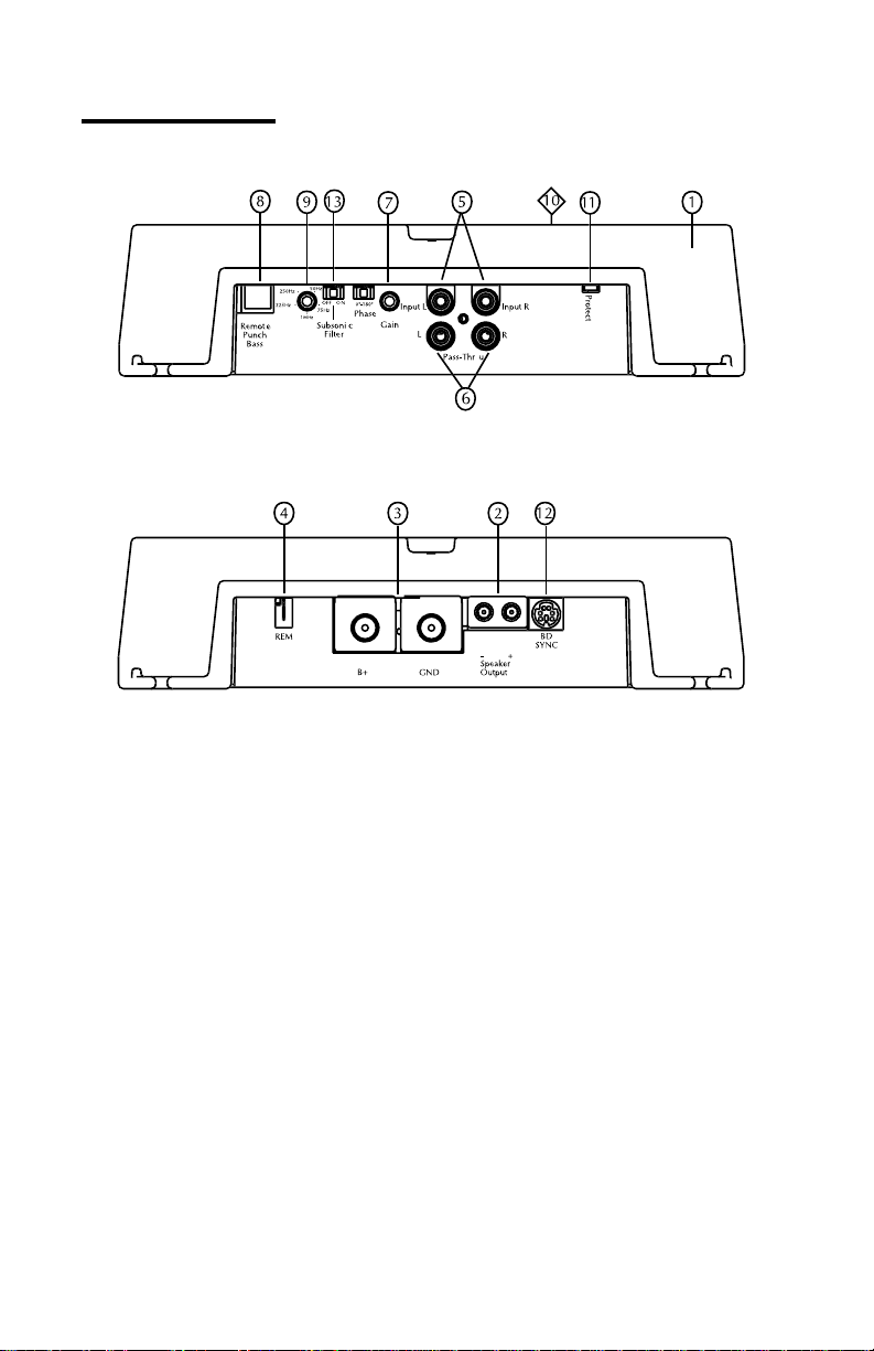
Design FeatureS
1. Cast Aluminum Heatsink – The cast aluminum heatsink of the Punch
amplifier dissipates heat generated by the amplifier's circuitry. The
inherent advantage of casting provides a 30% improvement of cooling
over conventional extrusion heatsink designs.
2.
Speaker Terminals – The heavy duty, gold-plated terminal block connectors (+ and –) will accept wire sizes from 8 A WG to 18 AWG. These
gold-plated connectors are immune to corrosion that can cause signal
deterioration.
3.
B+ and GND Terminals – The heavy duty, gold-plated terminal block
connectors (B+ and GND) will accept wire sizes from 4 AWG to 12
AWG. These gold-plated connectors are immune to corrosion that can
cause signal deterioration.
4.
REM Terminal – This spade terminal is used to remotely turn-on and
turn-off the amplifier when +12V DC is applied.
5.
RCA Input Jacks – The industry standard RCA jacks provide an easy
connection for signal level input. They are gold-plated to resist the signal degradation caused by corrosion.

5
6. RCA Pass-Thru Jacks – The Pass-Thru provides a convenient source for
daisy-chaining an additional amplifier without running an extra set of
RCA cables from the front of the vehicle to the rear amplifier location.
7.
Gain Control – The input gain control is preset to match the output of
most source units. It can be adjusted to match output levels from a
variety of source units.
8.
Remote Punch Bass - The Punch Bass control helps correct for acoustical deficiencies in the listening environment by helping reproduce full
range sound without excessive boost. The Punch Bass control is a narrow band adjustment centered at 45Hz variable from 0db to + 18db.
Connection is made with a cable using RJ - 45 and can be installed
under the dash for remote access.
9.
Variable Crossover – The amplifiers have a built-in 24dB/octave
Butterworth filter with a crossover point variable from 50Hz to 250Hz.
The crossover can be set to Low-Pass (LP).
10.
Power Indicator – The red logo on top illuminates when the unit is
turned on.
11.
Protect LED - The (red) LED illuminates when the unit is latched into
protection. It requires momentary AP removal to enable output PWM.
12. bd Sync Cable - The amplifiers have a 6 pin mini DIN connector.
When operating two amplifiers in the bridge mode, the SYNC cable
must be used. This will allow the two independent frequency carrier
generators in each unit to be synchronized.
13.
Subsonic Filter - A high pass filter designed to prevent frequencies
below the audio range from being applied to the core of the amplifier.
Consequently, improving loud speaker performance and power handling.
Design Features (Cont’d.)

6
Installation Considerations
This section focuses on some of the vehicle considerations for installing
your new Punch amplifier. Checking your battery and present sound system, as well as pre-planning your system layout and best wiring routes, will
save installation time. When deciding how to lay out your new system, be
sure that each component will be easily accessible for making adjustments.
Before beginning any installation, be sure to follow these simple rules:
1. Be sure to carefully read and understand the instructions before attempting to install the amplifier.
2.
For safety, disconnect the negative lead from the battery prior to beginning the installation.
3. For easier assembly, we suggest you run all wires prior to mounting
your amplifier in place.
4. Route all of the RCA cables close together and away from any high current wires.
5. Use high quality connectors for a reliable installation and to minimize
signal or power loss.
6.
Think before you drill! Be careful not to cut or drill into gas tanks, fuel
lines, brake or hydraulic lines, vacuum lines or electrical wiring when
working on any vehicle.
7. Never run wires underneath the vehicle. Running the wires inside the
vehicle provides the best protection.
8. Avoid running wires over or through sharp edges. Use rubber or plastic grommets to protect any wires routed through metal, especially the
firewall.
9.
ALWAYS protect the battery and electrical system from damage with
proper fusing. Install a fuseholder and appropriate fuse on the +12V
power wire within 18” (46 cm) of the battery terminal.
10. When grounding to the chassis of the vehicle, scrape all paint from the
metal to ensure a good, clean ground connection. Grounding connections should be as short as possible and always be connected to metal
that is welded to the main body, or chassis, of the vehicle.
 Loading...