


RF-TVMLPT01V2
TV Wall Mount
For wood-stud and concrete wall installations
Safety information and specifications ................................. |
2 |
Tools needed................................................................................. |
2 |
Package contents ........................................................................ |
3 |
Installation instructions............................................................. |
4 |
Assembly Guide
Before using your new product, please read these instructions to prevent any damage.
RF-TVMLPT01V2 TV Wall Mount
Safety information and specifications
IMPORTANT SAFETY INSTRUCTIONS - SAVE THESE INSTRUCTIONS
CAUTION: Do not use this product for any purpose not explicitly specified by Rocketfish.
Improper installation may cause property damage or personal injury. If
you do not understand these directions, or have doubts about the safety of the installation, contact Customer Service or call a qualified contractor. Rocketfish is not responsible for damage or injury caused by incorrect installation or use.
The weight of your TV must not exceed 50 lbs. (22.6 kg). The wall must be capable of supporting five times the weight of your TV and wall mount combined.
Maximum TV weight: 50 lbs. (22.6 kg)
Screen size: 13" to 26" diagonal
Overall dimensions (W × H ):
6.2 × 9.2 × 1.5 in. (15.7 × 23.3 × 3.8 cm)
Wall-mount weight: 1.6 lb. (0.7 kg)
We’re here for you www.rocketfishproducts.com For customer service, call:
800-620-2790 (U.S./Canada markets)
This product contains small items that could be a choking hazard if swallowed. Keep these items away from young children!
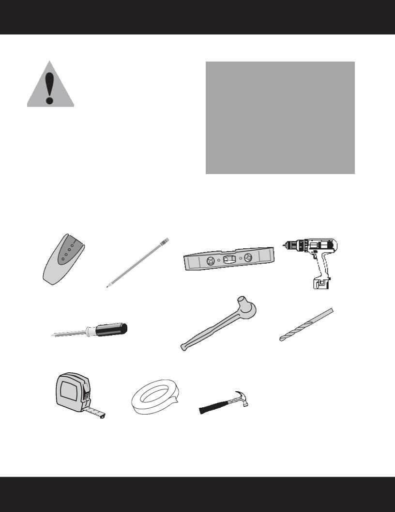
Tools needed
You will need the following tools to assemble your new TV wall mount:
Edge-to-edge stud finder
Phillips screwdriver
Level
Pencil
Socket wrench with 1/2" (13 mm) socket or adjustable wrench
Drill
7/32" (5.5 mm) wood drill bit for wood stud wall
OR
3/8" (10 mm) masonry drill bit (concrete only)
Measuring tape |
Tape |
Hammer |
|
||
|
|
2Need help? Call 1-800-620-2790 (U.S. and Canada) or 01-800-926-3010 (Mexico)
RF-TVMLPT01V2 TV Wall Mount
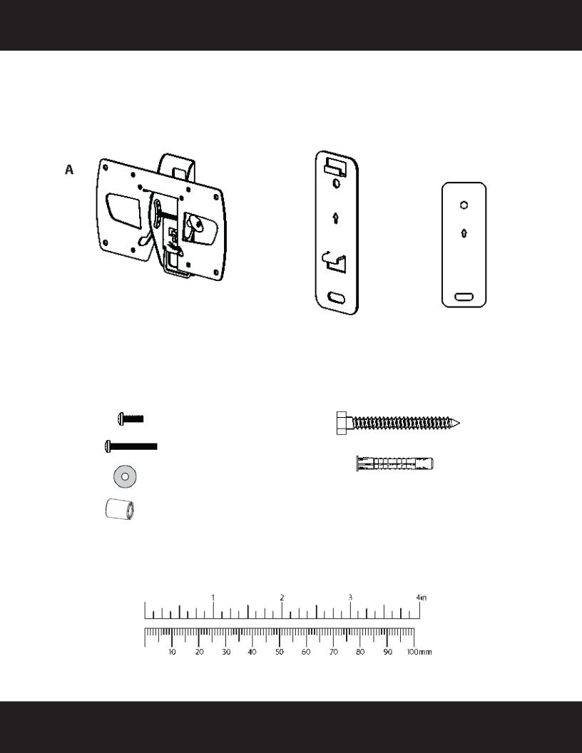
Package contents
Make sure that you have all the hardware necessary to assemble your new TV wall mount: A TV Bracket (1)
H Wall Plate (1)
I Template (1)
H I
TV Hardware Bag
Label |
Hardware |
Qty. |
|
|
|
|
|
B |
M4 × 12 mm |
4 |
|
screw |
|||
|
|
||
|
|
|
|
C |
M4 × 35 mm |
4 |
|
screw |
|||
|
|
||
|
|
|
|
D |
M4 washer |
4 |
|
|
|
|
|
E |
Universal spacers |
4 |
|
|
|
|
Label |
Hardware |
Qty. |
|
|
|
F |
|
2 |
|
5/16" × 2 3/4" lag bolt |
|
|
|
|
G |
Concrete anchors |
2 |
|
|
|
|
|
|
Need help? Call 1-800-620-2790 (U.S. and Canada) or 01-800-926-3010 (Mexico) |
3 |
RF-TVMLPT01V2 TV Wall Mount
Installation instructions
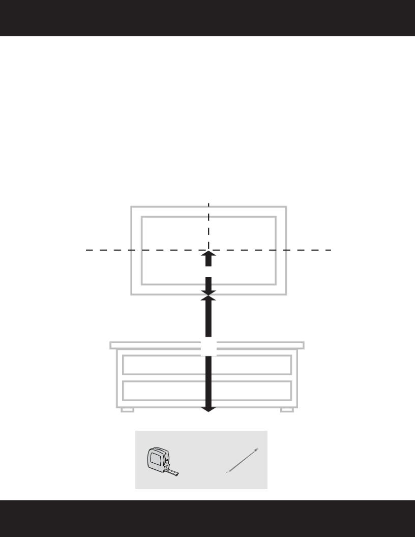
STEP 1 - Determine wall-mount location
Note:
•For more detailed information on determining where to drill your holes, visit our online height-finder at: http://mf1.bestbuy.selectionassistant.com/index.php/heightfinder
•Your TV should be high enough so your eyes are level with the middle of the screen. Normally, 40 to 60 inches from the ground.
The center of your TV will match the center of the TV bracket (A). Before you drill holes in the wall:
1Measure the distance from the bottom of your TV to the middle (half of the height of the TV). This is measurement a.
2Measure the distance from the floor to where you want the bottom of the TV to be placed on the wall. Keep in mind that the bottom of the TV should be placed above any furniture (such as entertainment centers or TV stands). The TV should also be above items placed on top of the furniture (like a Blu-ray player or cable box). This is measurement b.
3Add a + b. The total measurement is the height where you want the center of the TV bracket to be on the wall.
4Use a pencil to mark this spot on the wall.
a
b
You’ll need
Measuring tape |
Pencil |
|
|
|
|
4Need help? Call 1-800-620-2790 (U.S. and Canada) or 01-800-926-3010 (Mexico)

RF-TVMLPT01V2 TV Wall Mount
STEP 2 - Option 1: Installing on a wood stud wall
Note: Drywall covering the wall must not exceed 5/8" (16 mm).
1Locate the stud. Verify the center of the stud with an edge-to-edge stud finder.
2Align the wall plate template (I) at the height you determined in the previous step and make sure that it is level. Tape the wall plate template to the wall, then use a pencil to mark the lag bolt hole locations (2) on the stud centers. Remove the wall plate template.
3Drill pilot holes to a depth of 3 in. (75 mm) using a 7/32 in. (5.5 mm) diameter drill bit.
4Align the wall plate (H) with the pilot holes, insert the lag bolts (F) through the holes in the wall plate, then tighten the lag bolts only until they are firm against the TV bracket.
CAUTION: Avoid potential injuries or property damage!
DO NOT over-tighten the lag bolts (F).
Note: Minimum wood stud size: Common 2 x 4 in.
(51 x 102 mm). Nominal 1.5 x 3.5 in. (38 x 89 mm)
3 in
(75 mm)
You’ll need
F (2) |
|
|
|
|
|
|
|
|
|
Pencil |
|
|
7/32" wood |
1/2" socket |
Tape |
Level |
Template (I) |
Edge-to edge |
Wall plate (H) Drill |
drill bit |
|
||
|
wrench |
|
|||||
|
|
|
stud finder |
|
|
|
|
Need help? Call 1-800-620-2790 (U.S. and Canada) or 01-800-926-3010 (Mexico) |
5 |
 Loading...