


Wireless HD Audio Starter Kit
RF-RBKIT |
User Guide |

Wireless HD Audio Starter Kit
Contents |
|
Important safety instructions |
..................................... 3 |
Introduction ...................................................................... |
5 |
Features............................................................................... |
7 |
Using your wireless kit................................................. |
21 |
Troubleshooting ............................................................ |
30 |
Specifications.................................................................. |
31 |
Legal notices ................................................................... |
32 |
One-year limited warranty ......................................... |
35 |
2
The lightning flash with arrowhead symbol, within an equilateral triangle is intended to alert the user to the presence of uninsulated "dangerous voltage" within the product's enclosure that may be of sufficient magnitude to constitute a risk of electric shock to persons.
The exclamation point within an equilateral triangle is intended to alert the user to the presence of important operating and maintenance (servicing) instructions in the literature accompanying the appliance.
CAUTION:
TO REDUCE THE RISK OF ELECTRIC SHOCK:
DO NOT REMOVE SCREWS, COVERS OR THE CABINENT.
NO USER SERVICING PARTS INSIDE.
REFER SERVICING TO QUALIFIED SERVICE PERSONNEL.
WARNING: To reduce the risk of fire or electric shock, do not expose this apparatus to rain or moisture.
Important safety instructions
1 Read these instructions.
2 Keep these instructions.
3 Heed all warnings.
4 Follow all instructions.
5 Do not use this apparatus near water.
6 Clean only with a dry cloth.
7Do not block any ventilation openings. Install in accordance with the manufacturer's instructions.
8Do not install near any heat sources such as radiators, heat registers, stoves, or other apparatus (including amplifiers) that produce heat.
RF-RBKIT 3

9Do not defeat the safety purpose of the polarized or grounding-type plug. A polarized plug has two blades with one wider than the other. A grounding type plug has two blades and a third grounding prong. The wide blade or the third prong are provided for your safety. If the provided plug does not fit into your outlet, consult an electrician for replacement of the obsolete outlet.
10Protect the power cord from being walked on or pinched particularly at plugs, convenience receptacles, and the point where they exit from the apparatus.
11Only use attachments/accessories specified by the manufacturer.
12Unplug this apparatus during lightning storms or when unused for long periods of time.
13Refer all servicing to qualified service personnel. Servicing is required when the apparatus has been damaged in any way, such as power-supply cord or plug is damaged, liquid has been spilled or objects have fallen into the apparatus, the apparatus has been exposed to rain or moisture, does not operate normally, or has been dropped.
14To reduce the risk of fire or electric shock, do not expose this device to rain, moisture, dripping, or splashing, and no objects filled with liquids, such as vases, shall be placed on it.
15The wall plug is the disconnecting device. The plug must remain readily operable.
16Batteries should not be exposed to excessive heat such as sunshine, fire, or the like.
Caution: Danger of explosion if battery is incorrectly replaced. Replace only with the same or equivalent type.
Warning: Read the Rating Label on the bottom of the unit for power input and other safety information.
Caution - Proper Installation
Install the system in a place which is level, dry and neither too hot nor too cold. The appropriate temperature is between 5o C and 35 o C.
Install the system in a location with adequate ventilation to prevent internal heat from building up inside the unit.
Caution - Proper ventilation
To avoid risk of electric shock and fire, and to prevent damage, locate the apparatus as follows:
Front: No obstructions and open spacing.
Sides / Top / Back: No obstructions should be placed in the areas shown by the dimensions below.
4
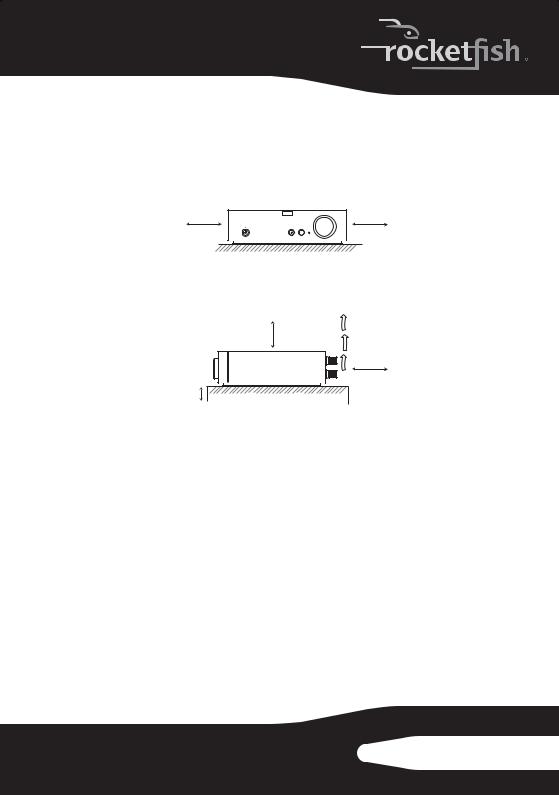
Bottom: Place on the level surface. Maintain an adequate air path for ventilation by placing on a stand with a height of 10 cm (3-15/16") or more.
Receiver ventilation requirements
|
Front view |
15 cm |
15 cm |
(5- 15/16") |
(5- 15/16") |
Side view
15 cm (5- 15/16")
15 cm
(5- 15/16")
10 cm (3- 15/16") |
Introduction
Congratulations on your purchase of a Rocketfish Wireless HD Surround System that is part of the Rocketboost™ system. The Rocketboost system uses a proprietary 2.4GHz Digital Audio technology to provide crystal clear sound and minimal interference. The different devices included in the Rocketboost system can connect to deliver whole-home wireless audio throughout your house. This kit includes a sender and a receiver. By using a single sender and one or more receivers in combination, the system can be built up in a 5.1- or 7.1-channel home theater system, or in more than one remote zone. This Rocketboost kit also supports HD quality audio for Blu-ray and other hi-definition sources.
Without the hassle of custom installation, the sender/receiver offers quick setup and total audio entertainment, without having to hide speaker wires.
RF-RBKIT 5

How does Rocketboost™ work?
Rocketboost technology can connect all audio devices throughout your home to form a convenient, private, and secure home audio network.
Every Rocketboost network must contain a device called a manager, which directs network data traffic and helps devices join the network. The network can have only one manager, which is selected using the Hub switch on the back of all Rocketboost senders. See the User Guide for instructions on joining devices to the network.
Each transmitter sends its own, two-channel stereo signal around the network, and any receiver can access the audio signal from any of the transmitters.
Rocketboost also features an innovative volume control that can be changed at the receiver or the transmitter. For example, when the transmitter's stream volume level is changed, all receivers listening to that stream have the same change in volume.
Rocketboost also features a global mute feature that instantly silences all connected devices. When turning off mute, only the stream that received the “unmute” command is affected. If there are other streams from other transmitters, they will not be affected by the unmute command. To unmute these streams, point the remote at a device which is muted from these streams.
We hope you enjoy your new Rocketboost system. Remember that it's designed to grow with your home entertainment needs, and that it's easy to add a new device to the network as you expand your entertainment system.
Manager
6

Features
•2.4 GHz unlicensed band operation
•Up to 150 feet (45 meters) unobstructed operating range
•Digital wireless operation
•Superior bass sound effects
•Support for CD and HD audio signals
•Four channels of wireless audio enables:
•5.1 wireless surround speakers
•7.1 wireless surround and rear speakers (optional RF-RBREC required)
•5.1 wireless surround speakers and wireless zone B audio (optional RF-RBREC required)
•Multi-zone, digital volume control
Package contents:
•Wireless sender
•Wireless receiver
•Rocketboost IR remote control
•DC adapter (for sender)
•AC cable (for receiver)
•User Guide
•Quick Setup Guide
•2 x 3.5mm Stereo Male-to-Male Cable (3 feet)
•2 x 3.5mm Stereo Female-to-RCA Male Cable (6 inches)
•4 x 3 feet of speaker cable
•Cable spool (for receiver)
RF-RBKIT 7
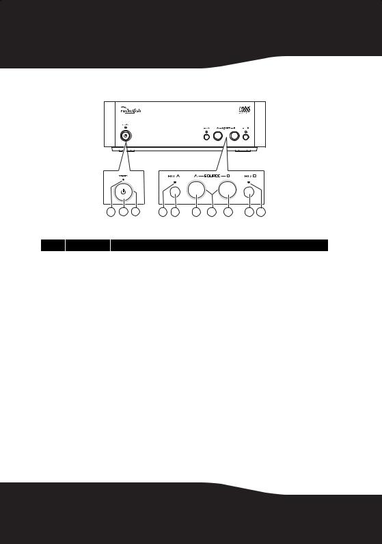
Sender front panel
TM
1 |
2 |
3 |
4 |
5 |
6 |
7 |
8 |
9 |
10 |
#Feature
1 |
|
Standby LED |
Turns red when the sender is in standby mode. |
|
|
|
|
2 |
|
Power/Join |
Press to turn the sender on. Press and hold to initiate joining. Press again to go to |
|
button |
standby. When the AC adapter is plugged in, the Sender automatically powers up. |
|
|
|
||
|
|
Power/Join |
Lights steady in power-on mode (green when the Hub Enable switch is set to “Enable.” |
3 |
|
indicator |
Blue when the Hub Enable switch is set to DISABLE) |
|
|
Blinks quickly in joining mode. |
|
|
|
|
|
|
|
|
Blinks slowly when the device is not part of a network or the hub is not powered. |
|
|
|
|
4 |
& 10 HD A/B indicator |
Lights when the high definition function is activated. |
|
|
|
|
|
5 |
& 9 |
HD A/B button |
Press repeatedly to toggle between CD and HD audio link modes for input A and input |
|
B respectively. When the HD function is activated, the audio quality will be enhanced. |
||
|
|
|
|
|
|
|
|
|
|
Source A/B |
Press to enable the source to be transmitted onto the network and press again to |
6 |
& 8 |
button |
disable the source. The status will be shown on the indicator. Make sure your hooked |
|
up speaker outputs match the enabled source, sound will not be sent unless the inputs |
||
|
|
|
|
|
|
|
connected have a corresponding activated source. |
7 |
|
Source A/B |
LED is illuminated steadily when a source is being transmitted. LED is off when no |
|
indicator |
source is enabled. LED blinks for a short while when a receiver selects this source to |
|
|
|
|
listen to. |
|
|
|
|
8
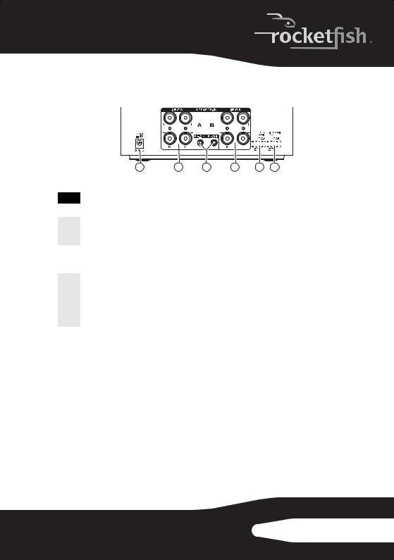
Sender back panel
|
|
|
|
2 |
|
|
|
|
|
|
|
|
|
|
|
|
|
|
|
|
|
|
|
|
|
|
|
|
|
|
|
|
|
|
|
|
|
|
|
|
|
|
|
|
|
|
|
|
|
|
|
|
|
|
|
|
|
|
|
|
|
|
|
|
|
|
|
|
|
|
|
|
|
|
1 |
3 |
4 |
5 |
|
|
6 |
|
|
|
|||||
|
|
|
|
|
|
|
|
|
|
|
|
|
|
|
|
|
|
# |
Feature |
|
|
|
|
|
|
|
|
|
|
|
|
|
|
|
|
1 |
DC IN jack |
Plug the DC adapter into this jack. |
|
|
|
|
|
|
|
|
|
|
|
||||
|
|
|
|
|
|
|
|
|
|
|
|
|
|
|
|||
2 & 4 |
SPEAKER IN A/B |
These inputs are used for an amplified output such as that from a receiver or HTIB. |
|||||||||||||||
|
|
Connect these inputs to your speaker out from your device just like you would |
|||||||||||||||
|
|
|
connect passive speakers. |
|
|
|
|
|
|
|
|
|
|
|
|
|
|
3 |
Pre-in A/B jack |
These inputs are used for line level audio applications such as Music output from an |
|||||||||||||||
|
|
MP3 player or DVD player. These devices will typically have either a 3.5mm connector |
|||||||||||||||
|
|
|
or RCA jacks. Adaptors for both are included in the kit. |
|
|
|
|
|
|||||||||
|
|
|
|
|
|
|
|
|
|
|
|
|
|
|
|||
|
Hub Enable |
Set switch to Enabled for hub operation. Set switch to Disable to disable hub |
|||||||||||||||
|
switch |
operation. |
|
|
|
|
|
|
|
|
|
|
|
|
|
|
|
5 |
|
|
Note: There should only be one hub in a network, please read “Establishing |
||||||||||||||
|
|
communication” on page 22 for more information. |
|
|
|
|
|
||||||||||
|
|
|
|
|
|
|
|
||||||||||
|
|
|
Switch to Disable if you already own a Rocketboost product, in which case you will |
||||||||||||||
|
|
|
already have a hub unit. |
|
|
|
|
|
|
|
|
|
|
|
|
|
|
6 |
4-channel lock |
Switch to ENABLE to synchronize the volume levels of inputs A and B, allowing 7.1 |
|||||||||||||||
switch |
systems to optimize speaker volume levels. |
|
|
|
|
|
|
|
|
|
|
||||||
|
|
|
Switch to DISABLE to allow separate control of the volume levels for Inputs A and B. |
||||||||||||||
Note: When four channel lock is enabled, other receivers will not be able to tune to the sources on the 4 channels. This is by design as most people would not want to listen to surrounds or rears only. If you wish to be able to tune to these sources remove the 4-channel lock.
RF-RBKIT 9
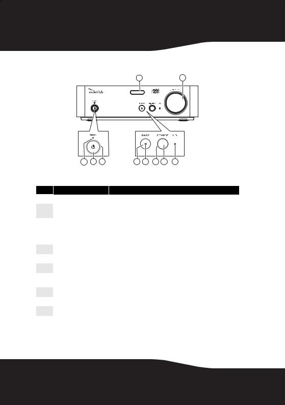
Receiver front panel
9 10
TM
1 |
2 |
3 |
4 |
5 |
6 |
7 |
8 |
#Feature
1 |
Standby LED |
Turns red when receiver is in standby mode. |
|
|
|
2 |
Power/Join button |
Press to turn the receiver on. Press and hold to initiate joining. Press |
|
again to go to standby. |
|
|
|
|
|
Power/Join indicator |
Lights steadily when powered on and successfully connected to a |
3 |
|
Rocketboost network. |
|
Blinks rapidly in joining mode. |
|
|
|
|
|
|
Blinks slowly when unable to connect to a network. |
|
|
|
4 |
BASS button |
Toggles Bass enhancement on or off. |
|
|
|
5 |
Bass indicator |
Lights when the bass enhancement is activated. |
|
|
|
6 |
SOURCE indicator |
Lights when the receiver is connected to an audio stream. |
|
|
|
7 |
SOURCE button |
Selects the audio source from A or B on the sender or from any other |
|
Rocketboost transmitter in the Rocketboost network. |
|
|
|
|
|
|
|
8 |
HD indicator |
Lights when the receiver is receiving HD audio signals. |
|
|
|
9 |
IR sensor window |
Receives the signal from the remote control. |
|
|
|
10 |
VOLUME knob |
Controls the volume level. |
|
|
|
10

Receiver back panel
SPEAKER-OUT (4-8 Ohm)
AC IN
120V~,60Hz
R L
1 2 3 4
#Feature
1 & 3 Removable cable spool slots |
Use to mount the cable spool on the receiver. |
|
|
|
|
2 |
AC IN connector |
Plug the AC power cord into this connector. |
|
|
|
4 |
SPEAKER OUT jacks |
Connect your speakers to these jacks. |
|
|
|
Remote control
|
5 |
1 |
6 |
2 |
7 |
3 |
8 |
|
|
4 |
|
#Feature
1 /| Standby/On button
2Volume /
/ buttons (device)
3BASS button
Press to turn the receiver on. Press again to go to standby. Press to adjust the volume of the speaker system.
Press to activate or deactivate bass enhancement.
RF-RBKIT 11
#Feature
4Next Source button
5INPUT A
6INPUT B
7Volume  /
/ buttons (stream)
 (mute - all)
8
Press to select the source from A or B or any other Rocketfish transmitter in your system.
Press to select between the audio source connecting SPEAKER Input A or Pre-In A.
Press to select between the audio source connecting SPEAKER Input B or Pre-In B.
Press to adjust the volume of all devices playing the stream being received.
Global mute - mutes all nodes in the system. Unmute will only unmute all devices receiving the same audio stream. To unmute others, press the Unmute button when pointing to a device rendering the particular stream.
Setting up your wireless kit
General Setup
Caution: Interference is possible from other devices that operate in the same frequency band. You may have to move the sender and/or receiver around a bit to find an interference-free location. We recommend a distance of at least 18” from a wireless router.
A few configurations are shown here to give ideas for your own usage.
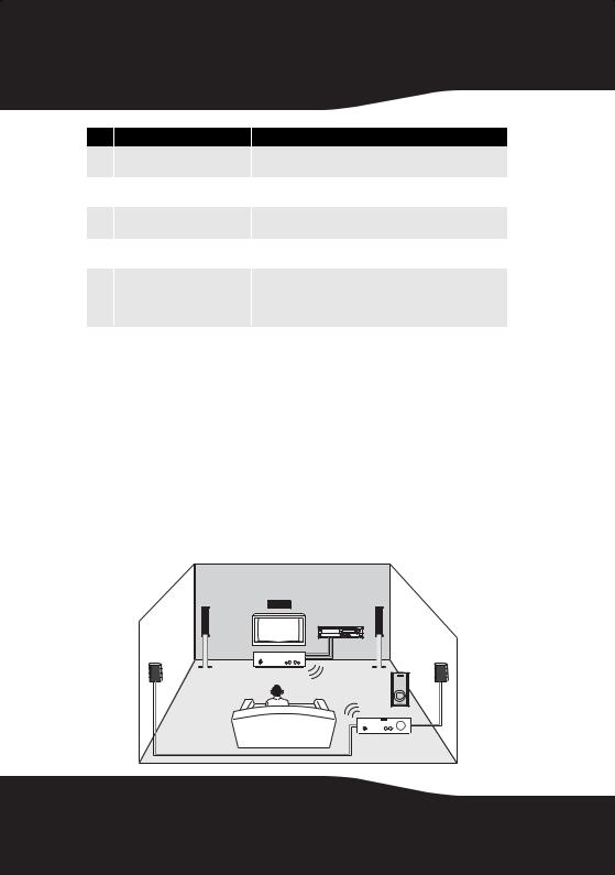
Building a 5.1-Channel Home Theater System
Amplifier |
TV |
Sender |
Receiver
12
 Loading...