


FOR YOUR SAFETY |
Combat |
|
|
6. |
supplier after leaving the building. |
|
|
If you smell gas: |
|
® |
|
1. |
Open windows. |
|
|
2. |
DO NOT try to light any appliance. |
|
|
3. |
DO NOT use electrical switches. |
|
|
4. |
DO NOT use any telephone in |
|
|
|
your building. |
|
|
5. |
Leave the building. |
Cabinet Heaters |
|
|
Immediately call your local gas |
|
|
|
Follow the gas supplier’s |
|
|
|
Installation, Commissioning, |
|
|
|
instructions. |
|
|
7. |
If you cannot reach your gas |
|
|
|
supplier, call the Fire Department. |
Operation & Service Manual |
|
|
|
|
|
|
WARNING |
|
|
|
|
|
|
OIL-FIRED: Model POP-ECA 015 to 0100
Fire Hazard |
GAS-FIRED: |
Do not store or use petrol or other |
Model PGP-ECA |
flammable vapours and liquids in the |
|
vicinity of this or any other appliance. |
015 to 0100 |
|
|
Some objects will catch fire or explode |
|
when placed close to heater. |
|
Failure to follow these instructions can |
|
result in death, injury or property |
|
damage. |
|
WARNING |
|
|
Installer |
|
|
|
|
|
|||
|
|
|
Please take the time to read and understand |
||
Improper installation, adjustment, alteration, service |
|||||
|
|
these instructions prior to any installation. |
|||
or maintenance can result in death, injury or property |
|
|
|||
|
|
Installer must give a copy of this manual to the owner. |
|||
damage. Read the installation, operation and service |
|
|
|||
|
|
|
|
||
manual thoroughly before installing or servicing |
|
|
Owner |
||
this equipment. |
|
|
|||
|
|
|
|
||
|
|
Keep this manual in a safe place in order to provide |
|||
|
|
|
|||
|
|||||
Installation must be done by a registered installer/ |
|||||
|
|
your serviceman with necessary information. |
|||
contractor qualified in the installation and service of |
|
|
|
|
|
gas/oil-fired heating equipment or your fuel supplier. |
|
|
|
|
|
|
|
|
|
||
|
|
|
|
|
|
|
Roberts-Gordon Europe Limited |
|
|
Unit A, Kings Hill Business Park |
|
|
Darlaston Road, Wednesbury |
|
|
West Midlands,WS10 7SH UK |
|
|
Telephone: +44 (0)121 506 7700 |
|
|
Fax: +44 (0)121 506 7701 |
|
|
Service Telephone: +44 (0)121 506 7709 |
|
Quality in Any Language™ |
Service Fax: +44 (0)121 506 7702 |
|
E-mail: uksales@rg-inc.com |
|
|
© Copyright 2008 Roberts-Gordon LLC |
E-mail: export@rg-inc.com |
P/N X523 Rev G 10/08 |

TABLE OF CONTENTS |
|
|
SECTION 1: Heater Safety...................................................... |
2 |
|
SECTION 2: Installer Responsibility ..................................... |
2 |
|
2.1 |
Clearances to Combustibles ........................................ |
2 |
2.2 |
Corrosive Chemicals.................................................... |
2 |
2.3 |
National Standards and Applicable Codes .................. |
2 |
SECTION 3: Critical Considerations ..................................... |
3 |
|
3.1 |
Basic Information......................................................... |
3 |
3.2 |
Location and Suspension ............................................ |
3 |
3.3 |
Minimum Required Installation Clearances ................. |
3 |
3.4 |
Clearances to Combustibles ........................................ |
3 |
3.5 |
Ventilation .................................................................... |
3 |
3.6 |
Fuel Supply.................................................................. |
3 |
3.7 |
Electrical Supply .......................................................... |
3 |
3.8 |
Flue.............................................................................. |
3 |
SECTION 4: Specifications .................................................... |
5 |
|
4.1 |
PGP & POP Internal Heaters....................................... |
5 |
4.2 |
PGP & POP External Heaters ..................................... |
6 |
4.3 |
Air Outlet and Flue Arrangements ............................... |
7 |
4.4 |
General Technical Data Table (all models) |
|
|
Appliance Category II 2H/L 3B/P ....................................... |
8 |
4.5 |
Technical Data - Ecoflam ON/OFF Burners |
|
|
(all models - burner reference "C") .............................. |
8 |
4.6 |
Technical Data - Ecoflam Modulating Burners |
|
|
(all models - burner reference "H") .............................. |
9 |
4.7 |
Technical Data - Ecoflam Oil-Fired Burners |
|
|
(burner reference "G") ............................................... |
10 |
SECTION 5: Heater Installation............................................ |
11 |
|
5.1 |
General...................................................................... |
11 |
5.2 |
Handling .................................................................... |
11 |
SECTION 6: Flue Installation ............................................... |
13 |
|
6.1 |
Flue Installation.......................................................... |
13 |
SECTION 7: Air Supply......................................................... |
15 |
|
7.1 Air Supply ................................................................... |
15 |
|
7.2 Isolated Equipment Rooms ........................................ |
15 |
|
7.3 Building Ventilation ..................................................... |
15 |
|
7.4 Distribution Ducting .................................................... |
15 |
|
7.5 Return Air Ducting ...................................................... |
15 |
|
SECTION 8: Fuel Piping........................................................ |
16 |
|
8.1 |
Connections............................................................... |
16 |
8.2 |
Fuel Oil Supply .......................................................... |
17 |
SECTION 9: Wiring and Electrical Information................... |
19 |
|
9.1 |
Electrical Supply ........................................................ |
19 |
9.2 |
Remote Controls ........................................................ |
19 |
9.3 |
CCH Wiring Diagram Gas Models 15-30 |
|
|
(floor standing)........................................................... |
20 |
9.4 |
CCH Wiring Diagram Oil Models 15-30 |
|
|
(floor standing)........................................................... |
21 |
9.5 |
CCH Wiring Diagram Gas Models 15-30 |
|
|
(horizontal mounting)................................................. |
22 |
9.6 |
CCH Wiring Diagram Oil Models 15-30 |
|
|
(horizontal mounting)................................................. |
23 |
9.7 |
CCH Wiring Diagram Gas Models 40-50 |
|
|
(floor standing)........................................................... |
24 |
9.8 |
CCH Wiring Diagram Oil Models 40-50 |
|
|
(floor standing)........................................................... |
25 |
9.9 |
CCH Wiring Diagram Gas Models 40-50 |
|
|
(horizontal mounting)................................................. |
26 |
9.10 CCH Wiring Diagram Oil Models 40-50 |
|
|
|
(horizontal mounting) ............................................... |
27 |
9.11 CCH Wiring Diagram Gas Models 60-100 |
|
|
|
(floor standing) ......................................................... |
28 |
9.12 |
CCH Wiring Diagram Oil Models 60-100 |
|
|
(floor standing) ......................................................... |
29 |
9.13 |
CCH Wiring Diagram Gas Models 60-100 |
|
|
(horizontal mounting) ............................................... |
30 |
9.14 |
CCH Wiring Diagram Oil Models 60-100 |
|
|
(horizontal mounting) ............................................... |
31 |
9.15 |
Final Connections to Ecoflam HIGH/LOW or |
|
|
Modulating Burners (all models) .............................. |
32 |
SECTION 10: Commissioning .............................................. |
33 |
|
10.1 |
Pre-Commission Checks .......................................... |
33 |
10.2 |
Commissioning the Burner (gas heaters)................. |
34 |
10.3 |
Control - Gas-Fired Heaters ..................................... |
35 |
10.4 |
Gas Valves ............................................................... |
37 |
10.5 |
Combustion Testing (all models) .............................. |
37 |
10.6 |
Commissioning the Burner (Oil Heaters).................. |
38 |
10.7 |
Control - Oil-Fired Heaters ....................................... |
38 |
10.8 |
Turning Off the Heater (all models) .......................... |
39 |
10.9 |
External Controls...................................................... |
39 |
10.10 Instruction to the User ............................................ |
39 |
|
SECTION 11: User Instructions............................................ |
40 |
|
11.1 User Instructions....................................................... |
40 |
|
11.2 Common User Controls (all models) ......................... |
40 |
|
11.3 Lighting Instructions (all models) .............................. |
41 |
|
11.4 Simple Fault Finding (all models).............................. |
41 |
|
SECTION 12: Servicing......................................................... |
43 |
|
12.1 |
Servicing Instructions............................................... |
43 |
12.2 |
Burner Maintenance................................................. |
43 |
12.3 |
Fan/Motor Assembly Maintenance (all models) ....... |
43 |
12.4 |
Heat Exchanger Maintenance .................................. |
43 |
12.5 |
Thermal Insulation ................................................... |
43 |
SECTION 13: Conversion Between FUELS ......................... |
44 |
|
13.1 |
General .................................................................... |
44 |
13.2 |
Burner Conversion ................................................... |
44 |
SECTION 14: Troubleshooting ............................................. |
45 |
|
14.1 |
General .................................................................... |
45 |
14.2 |
Troubleshooting for Oil Burners |
|
|
(see manufacture’s instructions) .............................. |
46 |
14.3 |
Troubleshooting for Gas Burners |
|
|
(see manufacturer’s instructions) ............................. |
47 |
14.4 |
Troubleshooting for Flame Supervision System ....... |
48 |
14.5 |
Troubleshooting for Solenoid Valves Circuit ............. |
49 |
14.6 |
Troubleshooting for Main Fan Circuit (1 Ø)............... |
49 |
14.7 |
Troubleshooting for Main Fan (3 Ø).......................... |
50 |
SECTION 15: Removal and Replacement Parts.................. |
51 |
|
15.1 |
Burner Components .............................................. |
51 |
15.2 |
Direct On-Line Main Fan Starter and |
|
|
Thermal Overload Unit (3 Ø) ................................... |
51 |
15.3 |
Control Circuit Fuse |
|
|
(10 or 5 A, 1-1/4" long sand filled)............................ |
51 |
15.4 |
Combination Fan/Limit Thermostat .......................... |
51 |
15.5 |
Main Fan Motor (3 Ø Belt Drive) .............................. |
51 |
15.6 |
Main Fan Units ......................................................... |
51 |
SECTION 16: Parts List......................................................... |
53 |
|
16.1 |
Spare Parts List........................................................ |
53 |
© 2008 Roberts-Gordon LLC
All rights reserved. No part of this work covered by the copyrights herein may be reproduced or copied in any form or by any means - graphic, electronic, or mechanical, including photocopying, recording, taping or information storage and retrieval systems - without the written permission of Roberts-Gordon LLC.
Printed in U.K.


TABLE OF FIGURES |
|
Figure 1: Installation Clearances and Clearances to |
|
Combustibles ............................................................. |
4 |
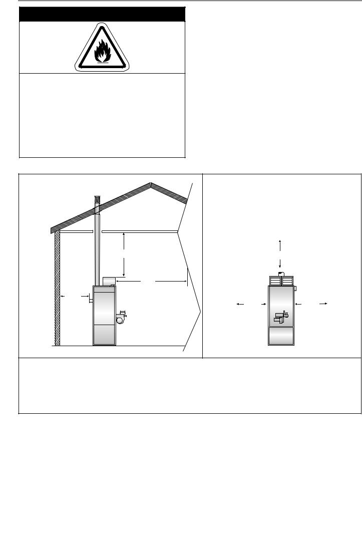
Figure 2: Typical Installation of a Gas Fired Cabinet Heater ... |
11 |
Figure 3: Typical Installation of a Oil-Fired Cabinet Heater ..... |
12 |
Figure 4: Flue Termination ...................................................... |
13 |
Figure 5: Offset Flues with 135° bends ................................... |
13 |
Figure 6: Guy Wire .................................................................. |
14 |
Figure 7: Socket Direction....................................................... |
14 |
Figure 8: Flue and Roof Detail ................................................ |
14 |
Figure 9: Flue and Heater Spigot Joint Detail ......................... |
14 |
Figure 10: Gas Connection ..................................................... |
16 |
Figure 11: B. M. Oil Lifter......................................................... |
17 |
Figure 12: Pressurised System Installation - Duplex System .. |
18 |
Figure 13: Combination Thermostat (all models) .................... |
34 |
Figure 14: Gas-Fired Heater Control Box Sequence............... |
35 |
Figure 15: Motor Starter (models 040 -100 and Thermal |
|
Overload (models 060 - 100) ................................. |
36 |
Figure 16: Gas Train Circuit for Dungs Gas Valves |
|
(all models) ............................................................ |
36 |
Figure 17: Dungs Gas Valve ................................................... |
37 |
Figure 18: Oil-Fired Heaters Control Box Sequence ............... |
38 |
Figure 19: Heater Operating Sequence .................................. |
40 |
Figure 20: Fan/Limit Thermostat ............................................. |
40 |
Figure 21: Belt Tension ........................................................... |
43 |
Figure 22: Combination Fan/Limit Thermostat........................ |
52 |


Product Approval
ROBERTS GORDON® appliances have been tested and CE certified as complying with the essential requirements of the Gas Appliance Directive, the Low Voltage Directive, the Electromagnetic Compatibility Directive and the Machinery Directive for use with natural gas and LPG when installed, commissioned and maintained in accordance with these instructions.
These instructions refer to gas appliances designed to operate in the European Union.
Appliances designed for other countries (Non-European Union) are available on request.
Oil-fired versions are constructed to the same basic design criteria to burn fuel oil as specified below, but no similar testing is available for these products at the time of writing. Oil-fired appliances should be operated in accordance with local rules and laws.
Oil heaters are supplied as standard for use with Gas Oil, also known as 35-second Oil, Red Diesel, Class D or Class A2. They are also available to order for Kerosine, also known as 28-second Oil or Class C2.
These appliances must be installed in accordance with the local and national codes in force and used only in a sufficiently ventilated space, as specified in these instructions.
Before installation, check that the local gas distribution systems, nature of gas and pressure, and adjustment of the appliance are compatible.
1

COMBAT® CABINET HEATERS INSTALLATION, COMMISSIONING, OPERATION AND SERVICE MANUAL
SECTION 1: HEATER SAFETY
Your Safety Is Important to Us! This symbol is used throughout the manual to notify you of possible fire,
electrical or burn hazards. Please pay special attention when reading and
following the warnings in these sections. Installation, Service and Annual Inspection of heater must be done by a registered installer/contractor qualified in the installation and service of gas/oilfired heating equipment.
Read this manual carefully before installation, operation, or service of this equipment.
Burner manufacturers manual is also provided to give detailed instructions on the operation of the burner. The settings for use of the burner with the heater are shown in these instructions.
This heater is designed for heating non-residential indoor spaces. Do not install in residential spaces. These instructions, the layout drawing, local codes and ordinances, and applicable standards that apply to gas piping, electrical wiring, venting, etc., must be thoroughly understood before proceeding with the installation.
SECTION 2: INSTALLER RESPONSIBILITY
•To install the heater, as well as the fuel and electrical supplies, in accordance with applicable specifications and codes. Roberts-Gordon recommends the installer contact a local building inspector, Fire Officer or insurance company for guidance.
•To use the information given in this manual together with the local and national codes to perform the installation.
•To install the heater in accordance with the Clearances to Combustibles of this heater.
•To furnish all needed materials not furnished as standard equipment.
•To plan location of supports, flues and air intakes.
•To provide access to burners for servicing.
•To provide the owner with a copy of this installation, commissioning, operation and service manual.
•To never use heater as support for ladder or other access equipment and never hang or suspend anything from heater.
•To ensure that there is sufficient ventilation in the area to comply with the requirements of
all relevant local and national codes.
2.1 Clearances to Combustibles
In all situations, clearances to combustibles must be maintained. Caution must be used when running the heater near combustible materials such as wood, paper, rubber, etc. A wall tag is on the back cover of this manual as a permanent reminder of the safety instructions and the importance of the required
clearances to combustibles. Affix the tag on a wall near the heater.
2.2 Corrosive Chemicals
 CAUTION
Do not use heater in an area containing corrosive chemicals.
Corrosive chemicals will damage the burner and heat exchanger parts.
Failure to follow these instructions can result in property damage.
Roberts-Gordon cannot be responsible for ensuring that all appropriate safety measures are undertaken prior to installation; this is entirely the responsibility of the installer. It is essential that the contractor, the sub-contractor or the owner identifies the presence of combustible materials, corrosive chemicals or halogenated hydrocarbons* anywhere on the premises.
* Halogenated Hydrocarbons are a family of chemical compounds characterized by the presence of halogen elements (fluorine, chlorine, bromine, etc.). These compounds are frequently used in refrigerants, cleaning agents, solvents, etc. If these compounds enter the air supply of the burner, the lifespan of the heater components will be greatly reduced. Warranty will be invalid if the heater is exposed to halogenated hydrocarbons.
2.3 National Standards and Applicable Codes
All appliances must be installed in accordance with the latest revision of applicable standards and local and national codes. This refers also to the electric, gas and venting installation. NOTE: Additional standards for installations in Public Garages, Aircraft Hangars, etc. may be applicable.
The main relevant regulations for installation within the UK are:
•Gas safety (installation and use) regulations, 1984 and amendments - 1996.
•BS6230 - Specification for the installation of gas fired forced convection air heaters for commercial and industrial space heating of rated input exceeding 60kW. (This standard also applies to oil-fired heaters, except for the fuel supply).
•BS6230 - Parts 2 & 3, fire precautions in the design and construction of buildings.
•BS6891 - Low pressure installation pipes.
•BS5410 - Codes of practice for oil firing. Part 2 installation of 44 kW and above output capacity for space heaters, hot water and steam supply purposes.
•Institute of Gas Engineers document IGE/UP/2.
•Building regulations.
•IEE regulations.
•Health and safety at work acts.
•Requirements of local authority, fire officer and insurance company.
2

SECTION 3: CRITICAL CONSIDERATIONS
SECTION 3: CRITICAL CONSIDERATIONS 3.1 Basic Information
Cabinet heaters are supplied with burners suitable for on/off operation as standard. As an option, oilfired burners are available with two-stage operation and gas-fired burners are available with full modulation.
3.2 Location and Suspension
All models:
•Are designed to be installed indoors within the heated space. Special versions are available for installation outdoors.
•Are designed for floor standing vertical installation.
•Must be installed in a manner which allows all the upper panels and either of the lower side panels to be removed to provide access to all serviceable components.
•Must be placed on a firm, level, non-combustible surface that can support its weight. See Page 5,
Section 4.1 for weight details.
Horizontal models:
•Special versions supplied with steel channels to support the heater are available and may be mounted horizontally. When installed horizontally, the heater will normally lie on its left side when viewed from the burner. The same clearances and comments on panels must be used, except for the side the heater lies on.
3.3 Minimum Required Installation Clearances
Clearances around the heater and flue must be as indicated on Page 4, Figure 1 and Page 13, Figure 4 through Figure 5 to ensure access for servicing, and correct operation.
3.4 Clearances to Combustibles
Clearances must be as indicated on Page 4, Figure 1. If no clearances to combustibles are indicated, then installation clearances apply.
3.5 Ventilation
It is important to ensure adequate air circulation around the heater to supply air for combustion, ventilation and distribution in accordance with local and national codes.
3.6 Fuel Supply
It is important that the fuel supply pipe is sized correctly to provide the inlet pressure as stated on the heater data plate. The fuel supply pipe and electrical connections must not support any of the heater's weight.
3.7 Electrical Supply
A permanent 230 V, 50 Hz, 1 Ø is required on models 15 to 30 and 400 V, 50 Hz, 3 Ø and neutral required on models 40 to 100 (special version PGP and POP 040 and 050 models are available as belt drive). The heater also requires suitable energy controls in accordance with Section 9.
ON/OFF control, temperature control, time control, and frost protection are available as a remote control, which needs to be site wired for proper operation of the heater. Alternatively, any remote energy controls may be used which must be wired in accordance with Section 9.3 through Section 9.10.
3.8 Flue
Choose heater siting to allow for the proper location of the flue. Each heater must be fitted with an individual and correctly sized sealed flue system (See Page 13, Section 6).
3
COMBAT® CABINET HEATERS INSTALLATION, COMMISSIONING, OPERATION AND SERVICE MANUAL
 WARNING
Fire Hazard
Some objects will catch fire or explode when placed close to heater.
Keep all flammable objects, liquids and vapours the required distance away from the heater.
Failure to follow these instructions can result in death, injury or property damage.
Figure 1: Installation Clearances and Clearances to Combustibles
|
.6 m |
.6 m |
|
4 m |
|
.6 m |
*.6 m |
*.6 m |
|
The flue pipe must have clearance from combustibles by 5 cm.
If installed where individuals can come in contact with the pressure relief door or other hot components, adequate guarding must be provided.
All distances are minimum clearance requirements for service access, air flow and safety. *A service clearance of 1m is required on one side to allow for fan replacement.
4
SECTION 4: SPECIFICATIONS
SECTION 4: SPECIFICATIONS
4.1 PGP & POP Internal Heaters
|
Front View |
|
|
Side View |
|
|
Side View |
Rear View |
|||||||||||||||||||||||||||
(all models) |
|
(Models 015 - 050) |
(Models 060 - 0100) |
(all models) |
|||||||||||||||||||||||||||||||
|
|
|
|
|
|
|
|
|
|
|
|
|
|
|
|
|
|
|
|
|
|
|
|
|
|
|
|
|
|
||||||
|
|
|
|
|
|
|
|
|
|
|
|
|
|
|
|
D |
|
|
|
|
|
|
|
|
|
|
D |
|
|||||||
|
|
|
|
|
|
|
|
|
|
|
|
|
|
|
|
|
|
|
|
|
|
|
|
|
|
|
|
|
|
|
|
|
|
|
|
|
|
|
|
|
|
|
|
|
|
|
|
|
|
|
|
|
|
|
|
|
|
|
|
|
|
|
|
|
|
|
|
|
|
|
|
|
|
|
|
|
|
|
|
|
|
|
|
|
|
|
|
|
|
|
|
|
|
|
|
|
|
|
|
|
|
|
|
|
|
|
|
|
|
|
|
|
|
|
|
|
|
|
|
|
|
|
|
|
|
|
|
|
|
|
|
|
|
|
|
|
|
|
|
|
|
|
|
|
|
|
|
|
|
|
|
|
|
|
|
|
|
|
|
|
|
|
|
|
|
|
|
|
|
|
|
|
|
|
|
|
|
|
|
|
|
|
|
|
|
|
|
|
|
|
|
|
|
|
|
|
|
|
|
|
|
|
|
|
|
|
|
|
|
|
|
|
|
|
|
|
|
|
|
|
|
|
|
|
|
|
|
|
|
|
|
|
|
|
|
|
|
|
|
|
|
|
|
|
|
|
|
|
|
|
|
|
|
|
|
|
|
|
|
|
|
|
|
|
|
|
|
|
|
|
|
|
|
|
|
|
|
|
|
|
|
|
|
|
|
|
|
|
|
|
|
E |
|
C |
|
|
|
|
|
|
|
|
|
|
|
|
|
|
|
|
|
|
|
|
|
|
|
|
|
|
|
|
|
|
|
|
|
|
|
|
|
|
|
|
|
|
|
|
|
|
|
|
|
|
|
|
|
|
|
|
|
|
|
|
|
|
|
|
|
|
|
|
|
|
|
|
|
|
|
|
|
|
|
|
|
|
|
|
|
|
|
|
|
|
|
|
|
|
|
|
|
|
|
|
|
|
|
|
|
|
|
|
|
|
|
|
|
|
|
|
|
|
|
|
|
|
|
|
|
|
|
|
|
|
|
|
|
|
|
|
|
|
|
|
|
||
|
|
|
|
|
|
|
|
|
|
|
|
|
|
|
|
|
|
|
|
|
|
|
|
|
|
|
|
|
|
|
|
|
|
|
|
|
|
|
|
|
|
|
|
|
|
|
|
|
|
|
|
|
|
|
|
|
|
|
|
|
|
|
|
|
|
|
|
|
|
|
|
|
|
|
|
|
|
|
|
|
|
|
|
|
|
|
|
|
|
|
|
|
|
|
|
|
|
|
|
|
|
|
|
|
|
|
|
|
|
|
|
|
|
|
|
|
|
|
|
|
|
|
|
|
|
|
|
|
|
|
|
|
|
|
|
|
|
|
|
|
|
|
|
|
|
|
|
|
|
|
|
|
|
|
|
|
|
|
|
|
|
|
|
|
|
|
|
|
|
|
|
|
|
|
|
|
|
|
|
|
|
|
|
|
|
|
|
|
|
|
|
|
|
|
|
|
|
|
|
|
|
|
|
|
|
|
|
|
|
|
|
|
|
|
|
|
|
|
|
|
|
|
|
|
|
|
|
|
|
|
|
|
|
|
|
|
|
|
|
|
|
|
|
|
|
|
|
|
|
|
|
|
|
|
|
|
|
|
|
|
|
|
|
|
|
|
|
|
|
|
|
|
|
|
|
|
|
|
|
|
|
|
|
|
|
|
|
|
|
|
|
|
|
|
|
|
|
|
|
|
|
|
|
|
|
|
|
|
|
|
|
|
|
|
|
|
|
|
|
|
|
|
|
|
|
|
|
|
|
|
|
|
|
|
|
|
|
|
|
|
|
|
|
|
|
|
|
|
|
|
|
|
|
|
|
|
|
|
|
|
|
|
|
|
|
||||
|
|
|
|
|
|
|
|
|
|
|
|
|
|
|
|
|
|
|
G |
|
|
|
|
|
|
|
|
|
|
|
|
|
|
|
|
|
G |
|
|
|
|
|
|
|
|
|
|
|
|
|
|
|
G |
|
|
|
|
|
|
|
|
||||||||||||
|
|
|
|
|
|
|
|
|
|
|
|
|
|
|
|
|
|
|
|
|
|
|
|
|
|
|
|
|
|
|
|
|
|
|
|
|
|
|
|
|
|
|
|
|
|
|
|
|
|
|
|
|
|
|
|
|
|
|
108 |
|
|
|
|
|
|
|
|
|
|
|
|
|
|
|
|
|
|
|
|
|
|
|
|
|
|
|
|
|
|
|
70 |
|
|
|
|
|
|
|
|
|
|
|
|
|
|
|
|
|
|
70 |
|
|
|
|
|
|
|
|
|
|
|
|
|
|
|
|
|
|
|
|
|
|
|
|
|
|
|
|
|
|
|
|
|
|
|
||
|
|
|
|
|
|
|
|
|
|
|
|
|
|
|
|
|
|
|
|
|
|
|
|
|
|
|
|
|
|
|
|
|
|
|
|
|
|
|
|
|
|
|
|
|
|
|
|
|
|
|
|
|
|
|
|
|
|
|
|
|
|
|
|
|
|
|
|
|
|
||||
|
|
|
|
|
|
|
|
|
|
A |
|
|
|
|
|
|
|
|
|
|
|
|
|
|
|
|
|
|
|
|
|
|
|
|
|
|
|
|
|
|
|
|
|
|
|
|
|
|
|
|
|
|
|
|
|
|
|
|
|
|
|
|
|
|
|
|
|
38 |
|||||
|
|
|
|
|
|
|
|
|
|
|
|
|
|
|
|
|
38 |
|
|
|
|
|
F |
|
|
|
|
|
|
|
38 |
|
38 |
|
|
|
|
|
|
|
|
|
|
F |
|
|
|
|
|
|
|
|
38 |
38 |
|
|
|
|
|
|
H |
|
|
|
|
||||||||
|
|
|
|
|
|
|
|
|
|
|
|
|
|
|
|
|
|
|
|
|
|
|
|
|
|
|
|
|
|
|
|
|
|
|
|
|
|
|
|
|
|
|
|
|
|
|
|
|
|
|
|
|
|
|
|
|
|||||||||||||||||
|
|
|
|
|
|
|
|
|
|
|
|
|
|
|
|
|
|
|
|
||||||||||||||||||||||||||||||||||||||||||||||||||||||
|
|
|
|
|
|
|
|
|
|
|
|
|
|
|
|
|
|
|
|
|
|
|
|
|
|
|
|
|
|
|
|
|
|
|
|
|
|
|
|
|
|
|
|
|
|
|
|||||||||||||||||||||||||||
|
|
|
|
|
|
|
|
|
|
|
|
|
|
|
|
|
|
|
|
|
|
|
|
|
B |
|
|
|
|
|
|
|
|
|
|
|
|
|
|
|
|
|
|
|
|
|
|
B |
|
|
|
|
|
|
|
|
|
|
|
|
|
|
|
|
|
|
|
|
|
|
|
|
|
|
|
|
|
|
|
|
|
|
|
|
|
|
|
|
|
|
|
|
|
|
|
|
|
|
|
|
|
|
|
|
|
|
|
|
|
|
|
|
|
|
|
|
|
|
|
|
|
|
|
|
|
|
|
|
|
|
|
|
|
|
|
|
|
|
|
|
|
|
|
|
|
||
|
|
|
|
|
|
|
|
|
|
|
|
|
|
|
|
|
|
|
|
|
|
|
|
|
|
|
|
|
|
|
|
|
|
|
|
|
|
|
|
|
|
||||||||||||||||||||||||||||||||
Dimension Data - PGP & POP Internal Heaters |
|
|
|
|
|
|
|
|
|
|
|
|
|
|
|
|
|
|
|
|
|
|
|
|
|
|
|
|
|
|
|
|
|
|
|
|
|
|
|||||||||||||||||||||||||||||||||||
|
|
|
|
|
|
|
|
|
|
|
|
|
|
|
|
|
|
|
|
|
|
|
|
|
|
|
|
|
|
|
|
|
|
|
|
|
|
|
|||||||||||||||||||||||||||||||||||
|
|
|
|
|
|
|
|
|
|
|
|
|
|
|
|
|
|
|
|
|
|
|
Model |
015/020 |
030 |
|
040 |
|
|
|
|
050 |
|
|
|
060/070/080 |
|
0100 |
|
|
|
||||||||||||||||||||||||||||||||
|
|
|
|
|
|
|
|
|
|
|
|
|
|
|
|
|
|
|
|
|
|
|
|
|
|
|
|
|
|
|
|
|
|
|
|
|
|||||||||||||||||||||||||||||||||||||
A |
|
Width |
|
|
|
|
|
|
mm |
724 |
724 |
|
857 |
|
|
|
|
1016 |
|
|
|
|
|
|
1016 |
|
|
|
|
|
|
|
|
1016 |
|
|
|
||||||||||||||||||||||||||||||||||||
|
|
|
|
|
|
|
|
|
|
|
|
|
|
|
|
|
|
|
|
|
|
|
(in) |
29 |
29 |
|
|
|
34 |
|
|
|
40 |
|
|
|
|
|
|
40 |
|
|
|
|
|
|
|
|
40 |
|
|
|
|
|
|||||||||||||||||||
B |
|
Depth, Cabinet Only |
|
|
|
|
|
|
mm |
857 |
857 |
|
|
857 |
|
|
|
|
1016 |
|
|
|
|
|
|
1676 |
|
|
|
|
|
|
|
|
1994 |
|
|
|
|||||||||||||||||||||||||||||||||||
|
|
|
|
|
|
|
|
|
|
|
|
|
|
|
|
|
|
|
|
|
|
|
(in) |
34 |
34 |
|
|
|
34 |
|
|
|
40 |
|
|
|
|
|
|
66 |
|
|
|
|
|
|
|
|
79 |
|
|
|
|
|
|||||||||||||||||||
C |
|
Height, Cabinet Only |
|
|
|
|
|
|
mm |
1740 |
1740 |
|
1930 |
|
|
|
|
1930 |
|
|
|
|
|
|
1930 |
|
|
|
|
|
|
|
|
1930 |
|
|
|
||||||||||||||||||||||||||||||||||||
|
|
|
|
|
|
|
|
|
|
|
|
|
|
|
|
|
|
|
|
|
|
|
(in) |
69 |
69 |
|
|
|
76 |
|
|
|
76 |
|
|
|
|
|
|
76 |
|
|
|
|
|
|
|
|
76 |
|
|
|
|
|
|||||||||||||||||||
D |
|
Depth, Overall |
|
|
|
|
|
|
mm |
1267 |
1267 |
|
1337 |
|
|
|
|
1496 |
|
|
|
|
|
|
2156 |
|
|
|
|
|
|
|
|
2496 |
|
|
|
||||||||||||||||||||||||||||||||||||
|
|
|
|
|
|
|
|
|
|
|
|
|
|
|
|
|
|
|
|
|
|
|
(in) |
50 |
50 |
|
|
|
53 |
|
|
|
59 |
|
|
|
|
|
|
85 |
|
|
|
|
|
|
|
|
98 |
|
|
|
|
|
|||||||||||||||||||
E |
|
Height, Including Heads |
|
|
|
|
|
|
mm |
1988 |
2058 |
|
2235 |
|
|
|
|
2235 |
|
|
|
|
|
|
2235 |
|
|
|
|
|
|
|
|
2235 |
|
|
|
||||||||||||||||||||||||||||||||||||
|
|
|
|
|
|
|
|
|
|
|
|
|
|
|
|
|
|
|
|
|
|
|
(in) |
78 |
81 |
|
|
|
88 |
|
|
|
88 |
|
|
|
|
|
|
88 |
|
|
|
|
|
|
|
|
88 |
|
|
|
|
|
|||||||||||||||||||
F |
|
Left/Right Air Inlet Spigot - Depth |
|
|
|
|
|
|
mm |
781 |
781 |
|
|
781 |
|
|
|
|
940 |
|
|
|
|
|
|
1600 |
|
|
|
|
|
|
|
|
1918 |
|
|
|
|||||||||||||||||||||||||||||||||||
|
|
|
|
|
|
|
|
|
|
|
|
|
|
|
|
|
|
|
|
|
|
|
(in) |
31 |
31 |
|
|
|
31 |
|
|
|
37 |
|
|
|
|
|
|
63 |
|
|
|
|
|
|
|
|
76 |
|
|
|
|
|
|||||||||||||||||||
G |
|
Left/Right Air Inlet Spigot - Height |
mm |
457 |
457 |
|
|
560 |
|
|
|
|
560 |
|
|
|
|
|
|
560 |
|
|
|
|
|
|
|
|
559 |
|
|
|
|
||||||||||||||||||||||||||||||||||||||||
|
|
|
|
|
|
|
|
|
|
|
|
|
|
|
|
|
|
|
|
|
|
|
(in) |
18 |
18 |
|
|
|
22 |
|
|
|
22 |
|
|
|
|
|
|
22 |
|
|
|
|
|
|
|
|
22 |
|
|
|
|
|
|||||||||||||||||||
H |
|
Rear Air Inlet Spigot - Depth |
|
|
|
|
|
|
mm |
648 |
648 |
|
|
781 |
|
|
|
|
781 |
|
|
|
|
|
|
NA |
|
NA |
|
||||||||||||||||||||||||||||||||||||||||||||
|
|
|
|
|
|
|
|
|
|
|
|
|
|
|
|
|
|
|
|
|
|
|
(in) |
26 |
26 |
|
|
|
31 |
|
|
|
31 |
|
|
|
|
|
|
|
|
|
|
|
|
|
|
|
|
|
|
|
|
|
|||||||||||||||||||
J |
|
Rear Air Inlet Spigot - Height |
|
|
|
|
|
|
mm |
361 |
361 |
|
|
446 |
|
|
|
|
446 |
|
|
|
|
|
|
NA |
|
NA |
|
||||||||||||||||||||||||||||||||||||||||||||
|
|
|
|
|
|
|
|
|
|
|
|
|
|
|
|
|
|
|
|
|
|
|
(in) |
14 |
14 |
|
|
|
18 |
|
|
|
18 |
|
|
|
|
|
|
|
|
|
|
|
|
|
|
|
|
|
|
|
|
|
|||||||||||||||||||
|
|
Flue Diameter* |
|
|
|
|
|
|
mm |
178 |
178 |
|
|
178 |
|
|
|
|
178 |
|
|
|
|
|
|
229 |
|
|
|
|
|
|
|
|
229 |
|
|
|
|
||||||||||||||||||||||||||||||||||
|
|
|
|
|
|
|
|
(in) |
7 |
7 |
|
|
|
|
7 |
|
|
|
|
7 |
|
|
|
|
|
|
9 |
|
|
|
|
|
|
|
|
9 |
|
|
|
|
|
||||||||||||||||||||||||||||||||
|
|
|
|
|
|
|
|
|
|
|
|
|
|
|
|
|
|
|
|
|
|
|
|
|
|
|
|
|
|
|
|
|
|
|
|
|
|
|
|
|
|
|
|
|
|
|
|
|
|||||||||||||||||||||||||
|
|
Weight |
|
|
|
|
|
|
|
|
kg |
200 |
200 |
|
|
245 |
|
|
|
|
270 |
|
|
|
|
|
|
440 |
|
|
|
|
|
|
|
|
530 |
|
|
|
|
||||||||||||||||||||||||||||||||
|
|
|
|
|
|
|
|
|
|
|
|
|
|
|
|
|
|
|
|
|
|
|
|
|
|
|
|
|
|
|
|
|
|
|
|
|
|
|
|
|
|
|
|
|
|
|
|
|
|
|
|
|
|
|
|
|
|
|
|
|
|
|
|
|
|
|
|
|
|
|
|
|
|
NOTES: Horizontal cabinet heaters are designed to lie on their left side as standard.
For vertical models, add 54 mm (2 in) to the right side of the cabinet for the fan/limit thermostat. For horizontal models, add 54 mm (2 in) to the top of the cabinet for the fan/limit thermostat. *All heaters must be connected to a suitable flue constructed of single wall stainless steel.
5

COMBAT® CABINET HEATERS INSTALLATION, COMMISSIONING, OPERATION AND SERVICE MANUAL
4.2 PGP & POP External Heaters
Front View |
|
|
|
Side View |
|
Rear View |
|||||||||||||||||
|
|
|
|
|
|
|
|
|
|
|
|
|
|
|
|
|
|
|
|
||||
|
|
|
|
|
|
|
|
|
|
|
|
|
|
|
|
|
|
F |
|||||
|
|
|
|
|
|
|
|
|
D |
|
|
|
|
||||||||||
|
275 |
|
|
|
|
|
|
|
|
|
|
|
|
|
|
H |
|
|
|
|
|||
|
|
|
|
|
|
|
|
|
|
|
|
|
|
|
|
|
|
|
|
||||
|
|
|
|
|
|
|
|
|
|
|
|
||||||||||||
|
|
P |
|
|
|
|
G |
|
|
|
|
|
|
|
|
|
|
|
|
|
|||
|
|
|
|
|
|
|
|
50 |
|
|
|
|
J |
|
|
|
|||||||
|
|
|
|
|
|
|
|
|
|
|
|
|
|
|
|
|
|||||||
|
|
|
|
|
|
|
|
|
|
|
|
|
|
|
|
|
|
|
|||||
|
|
|
|
|
|
|
|
|
|
|
|
|
|
|
|
|
|
|
|
|
|
|
|
|
|
|
|
|
|
|
|
|
|
|
|
|
|
|
|
|
|
|
|
|
|
|
|
|
|
|
|
|
|
|
|
|
|
|
|
|
|
|
|
|
|
|
|
|
|
|
|
|
|
|
|
|
|
|
|
|
|
|
|
|
|
|
|
|
|
|
|
|
|
|
|
|
|
|
|
|
|
|
|
|
|
|
|
|
|
|
|
|
|
|
|
|
|
|
|
|
|
|
|
|
|
|
|
|
|
|
|
|
|
|
|
|
|
|
|
|
|
|
|
|
|
|
|
|
|
|
|
|
|
|
|
|
|
|
|
|
|
|
|
|
|
|
|
|
|
|
|
|
|
|
|
|
|
|
|
|
|
|
|
|
|
|
|
|
|
|
|
|
|
|
|
|
|
|
|
|
|
|
|
|
|
|
|
|
|
|
|
|
|
|
|
|
|
|
|
|
|
|
|
|
|
|
|
|
|
|
|
|
|
|
|
|
|
|
|
|
|
|
|
|
|
|
|
|
|
|
|
|
|
|
|
|
|
|
|
|
|
|
|
|
|
|
|
|
|
|
|
|
|
|
|
|
|
|
|
|
|
|
|
|
|
|
|
|
|
|
|
|
|
|
|
|
|
|
|
|
|
|
|
|
|
|
|
|
|
|
|
|
|
|
|
|
|
|
|
|
|
|
|
|
|
|
|
|
|
|
|
|
|
|
|
|
|
|
|
|
|
|
|
|
|
|
|
|
|
|
|
|
|
|
|
|
|
|
|
|
|
|
|
|
|
|
|
|
|
|
|
|
|
|
|
|
|
|
|
|
|
|
|
|
|
|
|
|
|
|
|
|
|
|
|
|
|
|
|
|
|
|
|
|
|
|
|
|
|
|
|
C |
|
|
|
|
|
|
|
|
|
|
|
|
|
|
|
|
|
|
|
|
|
|
|
|
|
|
|
|
|
|
|
C |
|
|
|
|
|
|
|
|
|
|
|
|
|
|
|
|
|
|
|
|
|
|
|
|
|
|
|
|
|
|
|
|
|
|
|
|
|
|
|
|
|
|
|
|
|
|
|
|
|
|
|
|
|
|
|
|
|
|
|
|
|
|
|
|
|
|
|
|
|
|
|
|
|
|
|
|
|
|
|
|
|
|
|
|
|
|
|
|
|
|
|
|
|
|
|
|
|
|
|
|
|
|
|
|
|
|
|
|
|
|
|
|
|
|
|
|
|
|
|
|
|
|
|
|
|
|
|
|
|
|
|
|
|
|
|
|
|
|
|
|
|
|
|
|
|
|
|
|
|
|
|
|
|
|
|
|
|
|
|
|
|
|
|
|
|
|
|
|
|
|
|
|
|
|
|
|
|
|
|
|
|
|
|
|
|
|
|
|
|
|
|
|
|
|
|
|
|
|
|
|
|
M |
|
|
|
|
|
|
|
|
|
|
|
|
|
|
|
|
|
|
|
|
|
|
L |
|
|
|
|
|
|
|
|
|
|
|
|
|
|
|
|
|
|
|
|
|
|
|
|
|
|
|
|
|
|
70 |
|
|
|
|
|
|
|
|
|
|
|
|
|
|
|
|
|
|
|
|
|
|
108 |
|
|
|
|
|
|
|
|
|
|
|
|
|
|
|
|
|
|
|
|
|
|
|
|
|
|
|
|
|
|
|
|
|
|
|
|
|
|
|
|
|
|
|
|
|
|
|
|
|
|
|
|
|
|
|
|
|
|
|
|
|
|
|
|
|
|
|
|
||
|
|
|
|
|
|
|
|
|
|
|
|
|
|
|
|
|
|
|
|
|
|
|
|
|
|
|
|
|
|
|
|
|
|
|
|
|
|
|
|
|
|
|
|
|
|
|
|
|
|
|
|
|
||
|
|
|
|
|
|
|
|
|
|
|
|
|
|
|
|
|
|
|
|
|
|
|
|
|
|
|
|
|
|
|
|
|
|
|
|
|
|
|
|
|
|
|
|
|
|
|
|
|
|
|
|
|
||
|
|
|
|
|
|
|
A |
|
|
|
|
|
|
|
|
|
|
|
|
|
|
|
|
|
|
|
|
|
|
|
|
|
|
|
|
|
|
|
|
|
|
|
|
|
||||||||||
|
|
|
|
|
|
|
|
|
|
|
|
38 |
|
|
|
|
|
|
|
|
|
|
|
|
|
|
|
|
|
|
|
|
|
|
|
|
|
|
|
|
|
|
|
|
|
|
|
|
|
|||||
|
|
|
|
|
|
|
|
|
|
|
|
|
|
|
|
|
|
|
|
|
N |
|
|
|
|
|
38 |
|
|
|
|
|
|
|
38 |
|
|
|
|
|
K |
|
|
|
|
38 |
|
|||||||
|
|
|
|
|
|
|
|
|
|
|
|
|
|
|
|
|
|
|
|
|
|
|
B |
|
|
|
|
|
E |
|
|
|
|
|
|
|
|
|
|
|
|
|
|
A |
|
|
|
|
|
|
|
|
||
|
|
|
|
|
|
|
|
|
|
|
|
|
|
|
|
|
|
|
|
|
|
|
|
|
|
|
|
|
|
|
|
|
|
|
|
|
|
|
|
|
|
|
|
|
|
|
|
|
|
|||||
|
|
|
|
|
|
|
|
|
|
|
|
|
|
|
|
|
|
|
|
|
|
|
|
|
|
|
|
|
|
|
|
|
|
|
|
|
|
|
|
|
|
|
|
|
|
|
|
|
|
|||||
|
|
|
|
|
|
|
|
|
|
|
|
|
|
|
|
|
|
|
|
|
|
|
|
|
|
|
|
|
|
|
|
|
|
|
|
|
|
|
|
|||||||||||||||
Dimension Data - PGP & POP External Heaters |
|
|
|
|
|
|
|
|
|
|
|
|
|
|
|
|
|
|
|
|
|
|
|
|
|
|
|
|
||||||||||||||||||||||||||
|
|
|
|
|
|
|
|
|
|
|
|
|
|
|
|
|
|
|
|
|
|
|
|
|
|
|
|
|
|
|
|
|
|
|
||||||||||||||||||||
|
|
|
|
|
|
|
|
|
|
|
|
|
|
|
|
Model |
|
|
015/020/030 |
|
|
|
|
|
|
040 |
050 |
|
|
|
060/070/080 |
|
0100 |
|||||||||||||||||||||
|
|
|
|
|
|
|
|
|
|
|
|
|
|
|
|
|
|
|
|
|
|
|
|
|
|
|
|
|
|
|
|
|
|
|
|
|||||||||||||||||||
A |
Width |
mm |
|
|
724 |
|
|
|
|
|
|
|
|
|
857 |
857 |
|
|
|
1016 |
|
|
|
|
|
1016 |
||||||||||||||||||||||||||||
|
|
|
|
|
|
|
|
|
|
|
|
|
|
|
|
(in) |
|
29 |
|
|
|
|
|
|
|
|
|
34 |
34 |
|
|
|
40 |
|
|
|
|
|
40 |
|||||||||||||||
B |
Depth, Cabinet Only |
mm |
|
|
857 |
|
|
|
|
|
|
|
|
|
857 |
1016 |
|
|
|
1676 |
|
|
|
|
|
1994 |
||||||||||||||||||||||||||||
|
|
|
|
|
|
|
|
|
|
|
|
|
|
|
|
(in) |
|
34 |
|
|
|
|
|
|
|
|
|
34 |
40 |
|
|
|
66 |
|
|
|
|
|
79 |
|||||||||||||||
C |
Height, Cabinet Only |
mm |
|
|
1740 |
|
|
|
|
|
|
|
|
|
1930 |
1930 |
|
|
|
1930 |
|
|
|
|
|
1930 |
||||||||||||||||||||||||||||
|
|
|
|
|
|
|
|
|
|
|
|
|
|
|
|
(in) |
|
69 |
|
|
|
|
|
|
|
|
|
76 |
76 |
|
|
|
76 |
|
|
|
|
|
76 |
|||||||||||||||
D |
Depth Overall |
mm |
|
|
1396 |
|
|
|
|
|
|
|
|
|
1498 |
1657 |
|
|
|
2483 |
|
|
|
|
|
2800 |
||||||||||||||||||||||||||||
|
|
|
|
|
|
|
|
|
|
|
|
|
|
|
|
(in) |
|
55 |
|
|
|
|
|
|
|
|
|
59 |
65 |
|
|
|
98 |
|
|
|
|
|
110 |
|||||||||||||||
E |
External Heater Housing |
mm |
|
|
373 |
|
|
|
|
|
|
|
|
|
474 |
474 |
|
|
|
639 |
|
|
|
|
|
639 |
||||||||||||||||||||||||||||
|
|
|
|
|
|
|
|
|
|
|
|
|
|
|
|
(in) |
|
15 |
|
|
|
|
|
|
|
|
|
19 |
19 |
|
|
|
25 |
|
|
|
|
|
25 |
|||||||||||||||
F |
Width Overall |
mm |
|
|
840 |
|
|
|
|
|
|
|
|
|
973 |
973 |
|
|
|
1132 |
|
|
|
|
|
1132 |
||||||||||||||||||||||||||||
|
|
|
|
|
|
|
|
|
|
|
|
|
|
|
|
(in) |
|
33 |
|
|
|
|
|
|
|
|
|
38 |
38 |
|
|
|
45 |
|
|
|
|
|
45 |
|||||||||||||||
G |
Air Outlet Spigot - Depth |
mm |
|
|
476 |
|
|
|
|
|
|
|
|
|
476 |
610 |
|
|
|
1238 |
|
|
|
|
|
1524 |
||||||||||||||||||||||||||||
|
|
|
|
|
|
|
|
|
|
|
|
|
|
|
|
(in) |
|
19 |
|
|
|
|
|
|
|
|
|
19 |
24 |
|
|
|
49 |
|
|
|
|
|
60 |
|||||||||||||||
H |
Air Outlet Spigot - Width |
mm |
|
|
648 |
|
|
|
|
|
|
|
|
|
781 |
781 |
|
|
|
940 |
|
|
|
|
|
940 |
||||||||||||||||||||||||||||
|
|
|
|
|
|
|
|
|
|
|
|
|
|
|
|
(in) |
|
26 |
|
|
|
|
|
|
|
|
|
31 |
31 |
|
|
|
37 |
|
|
|
|
|
37 |
|||||||||||||||
J |
Flue Diameter |
mm |
|
|
178 |
|
|
|
|
|
|
|
|
|
178 |
178 |
|
|
|
229 |
|
|
|
|
|
229 |
||||||||||||||||||||||||||||
|
|
|
|
|
|
|
|
|
|
|
|
|
|
|
|
(in) |
|
7 |
|
|
|
|
|
|
|
|
|
7 |
7 |
|
|
|
9 |
|
|
|
|
|
9 |
|||||||||||||||
K |
Rear Return/Fresh Air Inlet - Width |
mm |
|
|
648 |
|
|
|
|
|
|
|
|
|
781 |
781 |
|
|
|
|
|
|
|
NA |
|
NA |
||||||||||||||||||||||||||||
|
|
|
|
|
|
|
|
|
|
|
|
|
|
|
|
(in) |
|
26 |
|
|
|
|
|
|
|
|
|
31 |
31 |
|
|
|
|
|
|
|
|
|
|
|
|
|
|
|
||||||||||
L |
Rear Return/Fresh Air Inlet - Height |
mm |
|
|
178 |
|
|
|
|
|
|
|
|
|
178 |
178 |
|
|
|
229 |
|
|
|
|
|
229 |
||||||||||||||||||||||||||||
|
|
|
|
|
|
|
|
|
|
|
|
|
|
|
|
(in) |
|
7 |
|
|
|
|
|
|
|
|
|
7 |
7 |
|
|
|
9 |
|
|
|
|
|
9 |
|||||||||||||||
M |
Left/Right Return Fresh Air Inlet - Height |
mm |
|
|
457 |
|
|
|
|
|
|
|
|
|
560 |
560 |
|
|
|
560 |
|
|
|
|
|
560 |
||||||||||||||||||||||||||||
|
|
|
|
|
|
|
|
|
|
|
|
|
|
|
|
(in) |
|
18 |
|
|
|
|
|
|
|
|
|
22 |
22 |
|
|
|
22 |
|
|
|
|
|
22 |
|||||||||||||||
N |
Left/Right Return Fresh Air Inlet - Width |
mm |
|
|
781 |
|
|
|
|
|
|
|
|
|
781 |
940 |
|
|
|
1600 |
|
|
|
|
|
1918 |
||||||||||||||||||||||||||||
|
|
|
|
|
|
|
|
|
|
|
|
|
|
|
|
(in) |
|
31 |
|
|
|
|
|
|
|
|
|
31 |
37 |
|
|
|
63 |
|
|
|
|
|
76 |
|||||||||||||||
P |
Rear of Heater to Air Outlet Spigot* |
mm |
|
|
401 |
|
|
|
|
|
|
|
|
|
401 |
426 |
|
|
|
96 |
|
|
|
|
|
96 |
||||||||||||||||||||||||||||
|
|
|
|
|
|
|
|
|
|
|
|
|
|
|
|
(in) |
|
16 |
|
|
|
|
|
|
|
|
|
16 |
17 |
|
|
|
4 |
|
|
|
|
|
4 |
|||||||||||||||
NOTE: *For Models 060-0100, the circular flue spigot is at the front of the heater, with the rectangular air outlet spigot at the rear. COMBAT® external cabinet heaters are designed to be sited externally, with heat ducted into the building. These models are fitted with a special metal rain drip cover, and all cabinet joints are silicone sealed to ensure that the heaters are weatherproof.
6

SECTION 4: SPECIFICATIONS
4.3 Air Outlet and Flue Arrangements
4.3.1 Vertical and Horizontal Heaters - Free Blowing (top view)
015/020
165 |
030 |
040 |
050 |
060/070/080 |
0100 |
165 |
203 |
229 |
|
|
|
|
|
||
|
|
|
184 |
284 |
|
|
|
|
NOTE: Models 015-020 are fitted with 229 mm (9") diameter discharge heads as standard. Models 030-0100 are fitted with 356 mm (14") diameter discharge heads as standard.
4.3.2 Vertical and Horizontal Heaters - Air Outlet Spigots (top view)
015/020/030
|
|
|
|
|
|
|
|
|
|
|
|
|
100 |
||||||||
|
|
|
|
|
|
|
|
|
|
|
|
|
|
|
|
|
|
|
|
|
|
|
|
|
|
|
|
|
|
|
|
|
|
|
|
|
|
|
|
|
|
|
|
|
|
|
|
|
|
|
|
|
|
|
|
|
|
|
|
343 |
|||||
|
|
|
|
|
|
|
|
|
|
|
|
|
|
|
|
|
|
|
|
|
|
|
|
|
|
|
|
|
|
|
|
|
|
|
|
|
|
|
|
||||
|
|
|
|
|
|
|
|
|
|
|
|
|
|
|
|
|
|
|
|||
|
|
|
|
|
|
|
|
|
|
|
|
|
|
|
|
L |
|
||||
|
|
|
|
|
|
|
|
|
|
|
|
|
|
|
|
|
|
|
|
|
|
|
|
|
|
|
|
|
|
|
|
|
|
|
|
|
38 |
||||||
38 |
|
|
|
|
|
|
|
|
|
|
|
|
38 |
||||||||
|
|
|
|
|
K |
|
|
|
|
|
|
||||||||||
|
|
|
|
|
|
|
|
|
|
|
|||||||||||
040 |
050 |
060/070/080 |
0100 |
|
|
|
|
|
|
|
|
|
|
|
|
|
100 |
|
|
|
|
|
|
|
|
|
100 |
38 |
|
|
|
|
|
|
K |
|
|
|
|
|
|
|
|
38 |
38 |
|
|
|
|
|
K |
|
|
|
|
|
|
|
38 |
|||||||||||||||
|
|
|
|
|
|
|
|
|
|
|
|
|
|
|
|
|
|
|
|
|
|
|
|
|
|
|
|
|
|
|
|
|
38 |
|
|
|
|
|
|
|
|
|
|
|
38 |
||||||||||||||||||||||
|
|
|
|
|
|
|
|
|
|
|
|
|
|
|
|
|
|
|
|
|
|
|
|
|
|
|
|
|
|
|
|
|
|
|
|
|
|
|
|
|
|
|
|
|
|
|
|
|
|
|
|
|
|
|
|
|
|
||||||||||
|
|
|
|
|
|
|
|
|
|
|
|
|
|
|
|
|
|
|
|
|
|
|
|
|
|
|
|
|
|
|
|
|
|
|
|
|
|
|
|
|
|
|
|
|
|
|
|
|
|
|
|
|
|
|
|
|
|
|
|
|
|
|
|
|
|
|
|
|
|
|
|
|
|
|
|
|
|
|
|
|
|
|
|
|
|
|
|
|
|
|
|
|
|
|
|
|
|
|
|
|
|
|
|
|
|
|
|
|
|
|
|
|
|
|
|
|
|
|
|
|
|
|
|
|
|
|
|
|
|
|
|
|
|
|
|
|
|
|
|
|
|
|
|
|
|
|
|
|
343 |
|
|
|
|
|
|
|
|
|
|
|
|
|
368 |
|
|
|
|
|
|
|
|
|
|
|
|
|
|
|
|
|
|
|
|
|
|
|
|
|
|
|
|
|
|
|
|
|
|
|
|||||
|
|
|
|
|
|
|
|
|
|
|
|
|
|
|
|
|
|
|
|
|
|
|
|
|
|
|
100 |
|
|
|
|
|
|
|
|
|
|
|
|
|
|
|
|
|
100 |
|
|
|
|
|
|
|
|
|
|
|
|
|
|
|
|||||||
|
|
|
|
|
|
|
|
|
|
|
|
|
|
|
|
|
|
|
|
|
|
|
|
|
|
|
|
|
|
|
|
|
|
|
|
|
|
|
|
|
|
|
|
|
|
|
|
|
|
|
|
|
|
|
|
|
|
|
|
|
|
|
|
|
|
|
|
|
|
|
|
|
|
|
|
|
|
|
|
|
|
|
|
|
|
|
|
|
|
|
|
|
|
|
|
|
|
|
|
|
|
|
|
|
|
|
|
|
|
|
|
|
|
|
|
|
|
|
|
|
|
|
|
|
|
|
|
|
|
|
|
|
|
|
|
|
|
|
|
|
|
|
|
|
|
|
|
|
|
L |
|
|
|
|
|
|
|
|
|
|
|
|
|
|
|
|
|
|
|
|
|
|
|
|
|
|
|
|
|
|
|
|
|
L |
|
|
|
|
|
|
|
|
|
|
|
|
|
L |
|
|
|
||
|
|
|
|
|
|
|
|
|
|
|
|
|
|
|
|
|
|
|
|
|
|
|
|
|
|
|
|
|
L |
|
|
|
|
|
|
|
|
|
|
|
|
|
|
|
|
|
|
|
|
|
|
|
|
|
|
|
|
||||||||||
|
|
|
|
|
|
|
|
|
|
|
|
|
|
|
|
|
|
|
|
|
|
|
|
|
|
|
|
|
|
|
|
|
|
|
|
|
|
|
|
|
|
|
|
|
|
|
|
|
|
|
|
|
|
|
|
|
|
|
|
|
|
|
|||||
|
|
|
|
|
|
|
|
|
|
|
|
|
|
|
|
|
|
|
|
|
|
|
|
|
|
|
|
|
|
|
|
|
|
|
|
|
|
|
|
|
|
|
|
|
|
|
|
|
|
|
|
|
|
|
|
|
|
|
|
|
|
|
|
|
|
|
|
|
|
|
|
|
|
|
|
|
|
|
|
|
|
|
|
|
|
|
|
|
|
|
|
|
|
|
|
|
|
|
|
|
|
|
|
|
|
|
|
|
|
|
|
|
|
|
|
|
|
|
|
|
|
|
|
|
|
|
|
|
|
|
|
|
|
|
|
|
|
|
|
|
|
|
|
|
|
|
|
|
|
|
|
|
|
|
|
|
|
|
|
|
|
|
|
|
|
|
|
|
|
|
|
|
|
|
|
|
|
|
|
|
|
|
|
|
|
|
|
|
|
|
|
|
|
|
|
|
|
|
|
|
|
|
|
|
|
|
|
|
|
|
|
|
|
|
|
|
38 |
|
|
|
|
|
|
|
|
|
|
|
|
|
|
|
|
|
|
|
|
|
|
|
|
|
|
|
|
|
|
|
|
|
|
|
|
|
|
|
|
|
|
|
|
|
|
|
|
|
|
|
|||
|
|
|
|
|
|
|
|
|
|
|
|
|
|
|
|
|
|
|
|
|
|
|
|
|
|
|
|
|
|
|
|
|
|
|
|
|
|
|
|
|
|
|
|
|
|
|
|
|
|
|
|
|
|
|
|
|
|
|
|
|
|
|
|
||||
38 |
|
|
|
|
|
|
|
|
|
|
|
|
|
|
|
38 |
|
|
|
|
|
|
|
|
|
|
|
|
38 |
|
|
|
|
|
|
|
|
|
|
|
|
|
|
|
|
400 |
|
|
|
|
|
|
|
|
|
|
|
|
|
|
|
|
|||||
|
|
|
|
|
|
|
|
K |
|
|
|
|
|
|
|
|
|
|
|
|
|
|
|
|
|
|
|
|
|
|
|
|
|
|
|
|
|
|
|
|
|
|
|
|
|
|
|
|
|
|
|
||||||||||||||||
|
|
|
|
|
|
|
|
|
|
|
|
|
|
|
|
|
38 |
|
|
|
|
|
|
|
|
|
|
|
|
|
38 |
|
|
|
|
|
|
|
|
|
|
|
|
|
|
|
|
|
|
|
|
|
|
|
|
|
|
|
|
|
|
|
|
|
|
|
|
|
|
|
|
|
|
|
|
|
|
|
|
|
|
|
|
|
|
|
|
|
|
|
|
K |
|
|
|
|
|
|
|
|
|
|
|
|
|
|
|
|
|
|
|
|
|
|
|
|
|
|
|
|
|
|
|
|
|
|
|
|
|
432 |
|||||
|
|
|
|
|
|
|
|
|
|
|
|
|
|
|
|
|
|
|
|
|
|
|
|
|
|
|
|
|
|
|
|
|
|
|
|
|
|
|
|
|
|
|
|
|
|
|
|
|
|
|
|
|
|
|
|
|
|
|
|
|
|
|
|
|
|
|
|
|
|
|
|
|
|
|
|
|
|
|
|
|
|
|
|
|
|
|
|
|
|
|
|
|
|
|
|
|
|
|
|
|
|
|
|
|
|
|
|
|
|
|
|
|
|
|
|
|
|
|
|
|
|
|
|
|
|
|
|
|
|
|
|
|
|
|
|
|
|
|
|
|
|
|
|
|
|
|
|
|
|
|
|
|
|
|
|
|
|
|
|
|
|
|
|
|
|
|
|
|
|
|
|
|
|
|
|
|
|
|
|
|
|
|
|
|
|
|
|
|
|
|
|
|
|
|
|
|
|
|
|
|
|
|
|
Outlet Spigot Dimensions
|
|
Model |
015/020/030 |
040 |
050 |
060/070/080 |
0100 |
|
|
|
|
|
|
|
|
K |
Spigot width |
mm |
648 |
781 |
781 |
940 |
940 |
|
|
(in) |
26 |
31 |
31 |
37 |
37 |
L |
Spigot Depth |
mm |
476 |
476 |
610 |
1238 |
1524 |
|
|
(in) |
19 |
19 |
24 |
49 |
60 |
7

COMBAT® CABINET HEATERS INSTALLATION, COMMISSIONING, OPERATION AND SERVICE MANUAL
4.4 General Technical Data Table (all models)
Appliance Category II 2H/L 3B/P
Model |
|
015 |
020 |
|
030 |
|
040 |
|
050 |
060 |
070 |
|
080 |
0100 |
|
|
|
|
|
|
|
|
|
|
|
|
|
||
Electrical Supply* |
|
|
|
230 |
V / 50 Hz / 1 Ø |
|
|
|
400 V / 50 Hz / 3 Ø |
|
||||
Main Fan Motor Type |
|
|
|
|
Direct Drive |
|
|
|
|
Belt Drive |
|
|||
Motor Size |
(kW) |
|
0.75 |
|
|
|
|
2.2 |
1.5 |
|
2.2 |
4.0 |
||
Motor Pulley |
(PCD) |
|
|
|
NA |
|
|
|
2 A x |
2 A x 95 mm |
2 A x |
|||
|
|
|
|
|
|
80 mm |
106 mm |
|||||||
|
|
|
|
|
|
|
|
|
|
|
|
|
||
Fan Pulley |
(PCD) |
|
|
|
NA |
|
|
|
2 A x |
2 A x |
|
2 A x |
2 A x |
|
|
|
|
|
|
|
180 mm |
180 mm |
|
180 mm |
180 mm |
||||
|
|
|
|
|
|
|
|
|
|
|
||||
Start Current |
(Amps) |
24 |
24 |
|
28 |
|
21 |
|
21 |
10.2 |
30 |
|
30 |
35 |
Run Current |
(Amps) |
5.3 |
5.3 |
|
6.3 |
|
6.2 |
|
6.2 |
3.5 |
5.1 |
|
5.1 |
9.6 |
Airflow |
(m3/h) |
3398 |
3398 |
|
5097 |
|
6796 |
|
8495 |
11044 |
12443 |
|
12443 |
17330 |
|
|
|
|
|
|
|
|
|
|
|
|
|
|
|
Free Blowing |
(ft3/min) |
2000 |
2000 |
|
3000 |
|
4000 |
|
5000 |
6500 |
7500 |
|
7500 |
10200 |
NOTE: *Models 40 & 50 are available with 230 V 1 Ø electrical supply as an extra cost option. A permanent uninterrupted electrical supply is required for all models.
When reading the following data tables, ensure that you are using the correct table for the burner and gas valve installed. The data tables include a burner reference letter that can be found on the heater data plate. Refer to the burner manufacturer’s instructions and the specific instructions supplement where applicable. The burner settings shown in the instructions must be used for burner settings.
4.5 Technical Data - Ecoflam ON/OFF Burners (all models - burner reference "C")
Model |
|
015 |
|
020 |
|
030 |
040 |
050 |
060 |
070 |
080 |
0100 |
|
|
|
|
|
|
|
|
|
|
|
|
|
Gross Heat Input |
(kW) |
55.5 |
|
73.3 |
|
93.2 |
129.9 |
162.0 |
208.0 |
242.0 |
275.2 |
348.5 |
(Btu/h) x (1000) |
189.4 |
|
250.1 |
|
318.0 |
443.2 |
552.7 |
709.7 |
825.7 |
939.0 |
1189.1 |
|
|
|
|
||||||||||
Net Heat Input |
(kW) |
50.0 |
|
66.0 |
|
84.0 |
117.0 |
146.0 |
187.4 |
218.0 |
248.0 |
314.0 |
(Btu/h) x (1000) |
170.6 |
|
225.2 |
|
286.6 |
399.2 |
498.2 |
639.4 |
743.8 |
846.2 |
1071.4 |
|
|
|
|
||||||||||
Heat Output |
(kW) |
47.4 |
|
61.2 |
|
78.4 |
110.2 |
134.5 |
177.7 |
205.3 |
230.4 |
293.4 |
(Btu/h) x (1000) |
161.7 |
|
208.8 |
|
267.5 |
376.0 |
458.9 |
606.3 |
700.5 |
786.1 |
1001.1 |
|
|
|
|
||||||||||
Pressure Switch Setting |
(mbar) |
|
1.5 |
|
4.5 |
4.0 |
6.5 |
5.0 |
6.5 |
7.5 |
7.0 |
|
Flue Static Pressure |
(mbar) |
-0.05 |
|
-0.05 |
|
-0.09 |
-0.30 |
-0.05 |
-0.25 |
-0.17 |
0.10 |
0.45 |
Gas Connection |
(in) |
|
|
3/4" |
|
|
|
|
1 1/4" |
|
|
|
|
|
|
|
|
|
|
|
|
|
|
|
|
Natural Gas (G20) Data - Inlet Pressure 20 mbar (7.8 in WG) |
Min 17 mbar (6.8 in WG) |
Max 25 mbar (10 in WG) |
|||||||||
|
|
|
|
|
|
|
|
|
|
|
|
Main Burner Gas Pressure |
mbar |
4.0 |
2.7 |
4.2 |
4.8 |
7.7 |
5.2 |
|
7.1 |
9.5 |
10.0 |
Start Gas Pressure |
mbar |
NA |
NA |
NA |
1.8 |
2.8 |
0.9 |
|
1.1 |
1.7 |
3.4 |
Gas Rate |
(m3/h) |
5.3 |
7.0 |
8.9 |
12.4 |
15.4 |
19.8 |
|
23.1 |
26.2 |
33.2 |
(ft3/h) |
187 |
247 |
314 |
438 |
546 |
701 |
|
816 |
928 |
1175 |
|
Start Gas Orifice |
(mm dia) |
|
|
|
5.0 |
6.0 |
7.0 |
|
7.0 |
7.0 |
|
Burner Type |
|
AZUR 60 |
BLU 120 |
BLU 120 |
BLU 170 |
BLU 250R |
BLU 250 |
BLU 250 |
BLU 250S |
BLU 350 |
|
Burner Head |
|
S |
S |
S |
S |
S |
S |
|
S |
S |
S |
Burner Head Setting |
(mm) |
0 |
10 |
11 |
15 |
14 |
24 |
|
24 |
24 |
21 |
Air Setting |
|
2.6 |
4.2 |
6 |
2.2 |
3.5 |
2.9 |
|
3.6 |
1.4 |
1.6 |
Valve Type Main Gas |
|
|
MBDLE |
|
MBDLE |
|
|
MBDLE |
|
MBDLE |
|
|
|
405 |
|
407 |
|
|
410 |
|
412 |
||
|
|
|
|
|
|
|
|||||
Valve Type Start Gas |
|
|
NA |
|
|
|
S.I.T. 0 832 051 |
|
|
||
|
|
|
|
|
|
|
|
|
|
|
|
LPG Gas Propane (G31) Data - Inlet Pressure 37 mbar (14.6 in WG) |
Min 25 mbar (10 in WG) |
Max 45 mbar (18 in WG) |
|||||||||
|
|
|
|
|
|
|
|
|
|
|
|
Main Burner Gas Pressure |
mbar |
4.2 |
3.3 |
4.6 |
|
4.8 |
7.5 |
5.8 |
7.8 |
12.0 |
7.6 |
Start Gas Pressure |
mbar |
NA |
NA |
NA |
|
1.6 |
2.5 |
0.8 |
1.0 |
1.5 |
3.1 |
Gas Rate |
(m3/h) |
2.1 |
2.8 |
3.5 |
|
4.9 |
6.1 |
7.8 |
9.1 |
10.4 |
13.1 |
(kg/h) |
3.9 |
5.1 |
6.5 |
|
9.1 |
11.3 |
14.5 |
16.9 |
19.2 |
24.3 |
|
|
|
||||||||||
Start Gas Orifice |
(mm dia) |
|
|
|
|
5.0 |
6.0 |
7.0 |
7.0 |
7.0 |
|
Main Gas Orifice |
(mm dia) |
8.5 |
10.0 |
10.0 |
|
14.5 |
14.5 |
14.5 |
14.5 |
14.5 |
|
Burner Type |
|
AZUR |
BLU |
BLU |
|
BLU |
BLU |
BLU |
BLU |
BLU |
BLU |
|
60 AH |
120 AH |
120 AH |
|
170 AH |
250R AH |
250 AH |
250 AH |
250S AH |
350 AH |
|
|
|
|
|||||||||
Burner Head |
|
S |
S |
S |
|
S |
S |
S |
S |
S |
LPG |
Burner Head Setting |
(mm) |
0 |
10 |
13 |
|
15 |
14 |
24 |
24 |
24 |
20 |
Air Setting |
|
3.0 |
4.8 |
6.6 |
|
2.6 |
4.5 |
3.1 |
4.2 |
1.6 |
1.8 |
Valve Type Main Gas |
|
|
MBDLE |
|
|
MBDLE |
|
MBDLE |
|
MBDLE |
|
|
|
405 |
|
|
407 |
|
410 |
|
412 |
||
|
|
|
|
|
|
|
|||||
Valve Type Start Gas |
|
|
NA |
|
|
|
|
S.I.T. 0 832 051 |
|
|
|
NOTE: For adjustment of head setting, see Ecoflam Instructions
8

SECTION 4: SPECIFICATIONS
4.6 Technical Data - Ecoflam Modulating Burners (all models - burner reference "H")
Model |
|
015 |
020 |
|
030 |
040 |
050 |
060 |
070 |
080 |
0100 |
|
|
|
|
|
|
|
|
|
|
|
|
Maximum Gross Heat Input |
(kW) |
55.5 |
73.3 |
|
93.2 |
129.9 |
162.0 |
208.0 |
242.0 |
275.2 |
348.5 |
(Btu/h) x (1000) |
189.4 |
250.1 |
|
318.0 |
443.2 |
552.7 |
709.7 |
825.7 |
939.0 |
1189.1 |
|
|
|
||||||||||
Maximum Net Heat Input |
(kW) |
50.0 |
66.0 |
|
84.0 |
117.0 |
146.0 |
187.4 |
218.0 |
248.0 |
314.0 |
(Btu/h) x (1000) |
170.6 |
225.2 |
|
286.6 |
399.2 |
498.2 |
639.4 |
743.8 |
846.2 |
1071.4 |
|
|
|
||||||||||
Minimum Gross Heat Input |
(kW) |
38.9 |
51.3 |
|
65.2 |
90.9 |
113.4 |
145.6 |
169.4 |
192.6 |
244.0 |
(Btu/h) x (1000) |
132.7 |
175.0 |
|
222.5 |
310.2 |
386.9 |
496.8 |
578.0 |
657.2 |
832.5 |
|
|
|
||||||||||
Minimum Net Heat Input |
(kW) |
35.0 |
46.2 |
|
58.8 |
81.9 |
102.2 |
131.2 |
152.6 |
173.6 |
219.8 |
(Btu/h) x (1000) |
119.4 |
157.6 |
|
200.6 |
279.5 |
348.7 |
447.7 |
520.7 |
592.3 |
750.0 |
|
|
|
||||||||||
Maximum Heat Output |
(kW) |
47.4 |
61.2 |
|
78.4 |
110.2 |
134.5 |
177.7 |
205.3 |
230.4 |
293.4 |
(Btu/h) x (1000) |
161.7 |
208.8 |
|
267.5 |
376.0 |
458.9 |
606.3 |
700.5 |
694.0 |
1001.1 |
|
|
|
||||||||||
Minimum Heat Output |
(kW) |
33 |
43 |
|
55 |
77 |
94 |
124 |
144 |
161 |
205 |
(Btu/h) x (1000) |
113 |
147 |
|
188 |
263 |
321 |
423 |
491 |
549 |
699 |
|
|
|
||||||||||
Pressure Switch Setting |
(mbar) |
|
1.5 |
|
|
1.0 |
|
1.5 |
|
2.0 |
2.5 |
Flue Static Pressure |
(mbar) |
-0.05 |
-0.05 |
|
-0.09 |
-0.30 |
-0.05 |
-0.25 |
-0.17 |
0.10 |
0.45 |
Gas Connection |
(in) |
|
|
3/4" |
|
|
|
1 1/4" |
|
|
|
Natural Gas (G20) Data - Inlet Pressure 20 mbar (7.8 in WG) |
Min 17 mbar (6.8 in WG) Max 25 mbar (10 in WG) |
||||||||||||
Main Burner Gas Pressure |
(mbar) |
4.9 |
2.4 |
3.3 |
4.1 |
6.7 |
5.2 |
|
6.7 |
|
8.0 |
|
8.6 |
Min. Burner Gas Pressure |
(mbar) |
3.2 |
2.8 |
2.4 |
2.3 |
3.7 |
2.5 |
|
3.4 |
|
4.3 |
|
5.4 |
Start Gas Pressure |
(mbar) |
NA |
NA |
NA |
1.1 |
1.8 |
0.6 |
|
0.7 |
|
0.9 |
|
1.0 |
Maximum Gas Rate |
(m3/h) |
5.3 |
7.0 |
8.9 |
12.4 |
15.4 |
19.8 |
|
23.1 |
|
26.2 |
|
33.2 |
(ft3/h) |
187 |
247 |
314 |
438 |
544 |
699 |
|
816 |
|
925 |
|
1172 |
|
Minimum Gas Rate |
(m3/h) |
3.8 |
5.0 |
6.3 |
8.8 |
11.0 |
14.2 |
|
16.5 |
|
18.7 |
|
23.7 |
(ft3/h) |
134 |
177 |
222 |
311 |
388 |
501 |
|
583 |
|
660 |
|
837 |
|
|
|
|
|
|
|
|
|
|
|
|
|
|
|
Start Gas Orifice |
(mm dia) |
NA |
NA |
NA |
|
|
|
7.0 |
|
|
|
|
|
Burner Type |
|
AZUR 60 |
BLU 120 |
BLU 120 |
BLU 170 |
BLU 250R |
BLU 250 |
|
BLU 250 |
|
BLU 250 |
|
BLU 350 |
Burner Head |
|
S |
S |
S |
S |
S |
S |
|
S |
|
S |
|
S |
Burner Head Setting |
(mm) |
0.0 |
8.0 |
10.0 |
15.0 |
14 |
|
|
T.O. |
|
|
|
|
Low Flame Air Orange Cam |
** |
20° |
13° |
22° |
|
18° |
|
|
22° |
|
25° |
|
|
High Flame Air Red Cam |
** |
33° |
40° |
80° |
30° |
32° |
30° |
|
35° |
|
55° |
|
60° |
Gas Valve Setting |
|
0-1, 5 |
0-1 |
|
|
|
0-1, 4 |
|
|
|
|
|
|
Valve Type Main Gas |
|
|
MBDLE 407 |
|
|
|
|
MBDLE 412 |
|
|
|
||
Valve Type Start Gas |
|
|
NA |
|
|
|
S.I.T. 0 832 051 |
|
|
|
|||
LPG Gas Propane (G31) Data - Inlet Pressure 37 mbar (14.6 in WG) Min 25 mbar (10 in WG) |
Max 45 mbar (18 in WG) |
|||||||||||
Main Burner Gas Pressure |
(mbar) |
4.3 |
5.7 |
4.7 |
3.1 |
5.9 |
5.3 |
7.2 |
|
9.0 |
|
6.4 |
Min. Burner Gas Pressure |
(mbar) |
2.3 |
2.9 |
1.4 |
1.6 |
2.0 |
2.3 |
2.5 |
|
3.2 |
|
2.0 |
Start Gas Pressure |
(mbar) |
NA |
NA |
NA |
1.1 |
1.7 |
0.6 |
0.7 |
|
0.7 |
|
1.5 |
Maximum Gas Rate |
(m3/h) |
2.09 |
2.76 |
3.51 |
4.89 |
6.10 |
7.83 |
9.11 |
|
10.36 |
|
13.12 |
(kg/h) |
3.87 |
5.11 |
6.49 |
9.05 |
11.29 |
14.49 |
16.86 |
|
19.18 |
|
24.29 |
|
|
|
|
||||||||||
Minimum Gas Rate |
(m3/h) |
1.46 |
1.93 |
2.46 |
3.42 |
4.27 |
5.48 |
6.38 |
|
7.25 |
|
9.18 |
(kg/h) |
2.71 |
3.58 |
4.55 |
6.34 |
7.90 |
10.15 |
11.80 |
|
13.42 |
|
17.00 |
|
|
|
|
||||||||||
Start Gas Orifice |
(mm dia) |
NA |
NA |
NA |
|
|
7.0 |
|
|
|
|
|
Main Gas Orifice |
(mm dia) |
8.5 |
10.0 |
|
|
14.5 |
|
|
|
|
NA |
|
Burner Type |
|
AZUR 60 |
BLU 120 |
BLU 120 |
BLU 170 |
BLU 250R |
BLU 250 |
BLU 250 |
|
BLU 250 |
|
BLU 350 |
Burner Head |
|
S |
S |
S |
S |
S |
S |
S |
|
S |
|
S |
Burner Head Setting |
(mm) |
0.0 |
8.0 |
10.0 |
15.0 |
14 |
|
T.O. |
|
|
|
|
Low Flame Air Orange Cam |
** |
20° |
13° |
22° |
|
18° |
|
22° |
|
25° |
|
|
High Flame Air Red Cam |
** |
33° |
40° |
80° |
30° |
32° |
30° |
35° |
|
55° |
|
60° |
Gas Valve Setting |
|
0-1, 4 |
0, 3-0, 9 |
|
0-1, 1 |
|
0-1, 4 |
|
0-1, 5 |
|
0-0, 85 |
|
Valve Type Main Gas |
|
|
MBDLE 407 |
|
|
|
MBDLE 412 |
|
|
|
||
Valve Type Start Gas |
|
|
NA |
|
|
|
S.I.T. 0 832 051 |
|
|
|
||
NOTE: The air setting is a guide only. The final setting is subject to combustion testing.
When setting the minimum firing rate, a check must be made following the setting of the burner combustion. The check is made by running the heater on low fire for a minimum of 15 minutes at the full transport air rate and at typical ambient conditions. During the test, check that the flue gas temperature does not fall below 125° C. Should the flue gas temperature fall below 100° C, then the low fire gas setting must be increased to a value that will achieve 125° C flue gas temperature; otherwise condensation may form in the heat exchanger and flue, causing rapid corrosion and short operational life.
NOTE: For adjustment of head setting, see Ecoflam Instructions.
9

COMBAT® CABINET HEATERS INSTALLATION, COMMISSIONING, OPERATION AND SERVICE MANUAL
4.7 Technical Data - Ecoflam Oil-Fired Burners (burner reference "G")
Model |
|
015 |
020 |
030 |
040 |
|
050 |
060 |
070 |
|
080 |
0100 |
|
|
|
|
|
|
|
|
|
|
|
|
|
Gross Heat Input |
(kW) |
55.5 |
73.3 |
93.2 |
129.9 |
|
162.0 |
208.0 |
242.0 |
|
275.2 |
348.5 |
(Btu/h) x (1000) |
189.4 |
250.1 |
318.0 |
443.2 |
|
552.7 |
709.7 |
825.7 |
|
939.0 |
1189.1 |
|
|
|
|
||||||||||
Heat Output |
(kW) |
47.4 |
61.2 |
78.4 |
110.2 |
|
134.5 |
177.7 |
205.3 |
|
230.4 |
293.4 |
(Btu/h) x (1000) |
161.8 |
208.9 |
267.4 |
375.9 |
|
458.8 |
606.5 |
700.3 |
|
786.2 |
1001.0 |
|
|
|
|
||||||||||
Burner Type |
|
Minor 8 |
Minor 12 |
Minor 20 |
|
Minor 30 |
|
Major 30 |
||||
Oil Pump Connections |
(in) |
|
|
|
|
3/8 |
|
|
|
|
|
|
|
|
|
|
|
|
|
|
|
|
|
|
|
Light Fuel Oil (Gas Oil) Data |
|
|
|
|
|
|
|
|
|
|
|
|
|
|
|
|
|
|
|
|
|
|
|
|
|
Nozzle Size |
*US (gal/h) |
1.00 |
1.50 |
1.75 |
2.50 |
|
3.50 |
4.00 |
5.00 |
|
5.00 |
7.00 |
Angle & Type |
|
|
|
60S |
|
|
|
|
60A |
|
|
|
Make |
|
|
|
Danfoss |
|
|
|
|
Delavan |
|
||
Head Setting |
(mm) |
8 |
0 |
14 |
|
|
|
(full back) |
|
|
|
(fixed) |
Air Setting |
(number) |
4.2 |
8.5 |
5.5 |
3 |
|
4 |
3.7 |
4 |
|
6.2 |
1.8 |
Burner Fuel Pressure |
(Bar) |
12.1 |
10.3 |
12.4 |
11.7 |
|
10.0 |
11.0 |
10.0 |
|
13.0 |
11.0 |
(lbf/in2) |
175 |
150 |
180 |
170 |
|
145 |
160 |
145 |
|
188 |
160 |
|
Fuel Consumption |
(L/h) |
5.17 |
6.82 |
8.68 |
12.09 |
|
15.08 |
19.36 |
22.53 |
|
25.62 |
32.44 |
*UK (gal/h) |
1.14 |
1.50 |
1.91 |
2.66 |
|
3.32 |
4.26 |
4.96 |
|
5.63 |
7.14 |
|
|
|
|
||||||||||
Maximum Oil Pressure to |
(Bar) |
|
|
|
|
.21 |
|
|
|
|
|
|
Pump Inlet |
(lbf/in2) |
|
|
|
|
3 |
|
|
|
|
|
|
|
|
|
|
|
|
|
|
|
|
|
|
|
|
|
|
|
|
|
|
|
|
|
|
|
|
Kerosene Data |
|
|
|
|
|
|
|
|
|
|
|
|
|
|
|
|
|
|
|
|
|
|
|
|
|
Nozzle Size |
*US (gal/h) |
1.25 |
1.75 |
2.50 |
3.00 |
|
4.00 |
5.00 |
6.00 |
|
6.50 |
8.50 |
Angle & Type |
|
|
|
|
|
|
60S |
|
|
|
|
60B |
Make |
|
|
|
|
|
|
Danfoss |
|
|
|
|
|
Head Setting |
(mm) |
8 |
0 |
14 |
|
|
|
(full back) |
|
|
|
(fixed) |
Air Setting |
(number) |
4 |
6.6 |
6 |
3 |
|
4 |
3.7 |
4.5 |
|
6 |
1.4 |
Burner Fuel Pressure |
(Bar) |
8.6 |
9.7 |
8.3 |
9.7 |
|
8.3 |
9.0 |
8.3 |
|
9.3 |
8.3 |
(lbf/in2) |
125 |
140 |
120 |
140 |
|
120 |
130 |
120 |
|
135 |
120 |
|
Fuel Consumption |
(L/h) |
5.47 |
7.23 |
9.19 |
12.81 |
|
15.98 |
20.52 |
23.87 |
|
27.14 |
34.37 |
*UK (gal/h) |
1.20 |
1.59 |
2.02 |
2.82 |
|
3.51 |
4.51 |
5.25 |
|
5.97 |
7.56 |
|
|
|
|
||||||||||
NOTE: For adjustment of head setting, see Ecoflam Instructions.
* Nozzle sizes are quoted in US gal/h. Fuel consumption is quoted in imperial gal/h.
10

SECTION 5: HEATER INSTALLATION
SECTION 5: HEATER INSTALLATION 5.1 General
Heaters are designed for floor standing vertical installation. Special versions supplied with steel channels to support the heater are available and may be mounted horizontally. When installed horizontally, the heater will normally lie on its left side when viewed from the burner. The heater
should be placed on a firm, level, non-combustible surface that can support its weight. See Page 5, Section 4.1 for weight details.
5.2 Handling
All cabinet heaters are supplied secured to a wooden pallet and shrink wrapped. Use the pallet to support the heater during handling and installation.
Figure 2: Typical Installation of a Gas Fired Cabinet Heater
|
Flues up to 200 mm dia. are |
|
fitted with Bird Screens, over |
1 m |
200 mm with a Rain Cap. |
|
|
Minimum |
|
|
Lead Roof Plate |
Flue |
|
|
Air |
|
|
Distribution |
Roof |
|
Heads |
||
|
Building Ventilation
Electric Supply
Gas Isolating Valve
Union
Connection
11
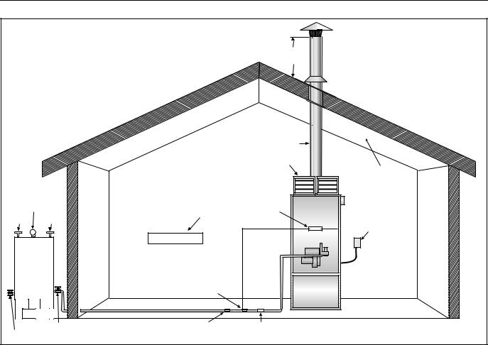
COMBAT® CABINET HEATERS INSTALLATION, COMMISSIONING, OPERATION AND SERVICE MANUAL
Figure 3: Typical Installation of a Oil-Fired Cabinet Heater
1 m Minimum

 Flues up to 200 mm dia. are
  fitted with Bird Screens, over 200 mm with a Rain Cap.
 Lead Roof Plate
Flue |
|
|
Air |
|
|
Distribution |
Roof |
|
Heads |
||
|
Gauge |
Building Ventilation |
Fusible |
|
Vent |
Filler |
Link |
|
|
Electric Supply |
||
|
|
|
|
Fuel |
|
|
|
Tank |
|
|
|
|
|
Fire Valve |
|
Gate Valve |
Manual Isolating Fuel Filter |
Plugged Drain Valve |
Valve |
12

SECTION 6: FLUE INSTALLATION
SECTION 6: FLUE INSTALLATION
6.1 Flue Installation
 WARNING
Fire Hazard
Some objects will catch fire or explode when placed close to heater.
Keep all flammable objects, liquids and vapours the required distance away from the heater.
Failure to follow these instructions can result in death, injury or property damage.
Flues must be correctly sized for the model. See Page 5, Section 4.1. Flues should be assembled as on Page 13, Figure 4 and Figure 5 and Page 14,
Figure 6 through Page 14, Figure 9. The joints between the flue and the roof or wall must be properly sealed. If the flue passes through a wall or ceiling of combustible material it must be enclosed by a sleeve of non-combustible material and be separated from the sleeve by at least a 25 mm air gap.
Flues must be adequately supported so that the heater does not bear the weight of the flue.
For straight and offset flue termination See Page 13, Figure 4 and Figure 5.
90° bends and horizontal pipe must not be used in flues except for the immediate connection to horizontally mounted heaters (1 m max). 135° bends are used to offset the flue as in Figure 5.
If condensation is likely to occur in the flue, then provision should be made for drainage.
Figure 4: Flue Termination |
Figure 5: Offset Flues with 135° bends |
Flues up to 200 mm dia. are fitted with Bird Screens, over 200 mm with a Rain Cap.
1 m |
*1 m |
|
Minimum |
Minimum Nearby |
|
|
Structure |
|
*Less than |
|
|
2.5 m |
|
|
Roof |
|
|
Use adequate |
|
|
support to |
|
|
prevent heater |
*If the point |
|
from carrying |
||
the weight of |
of roof |
|
the flue. |
intersection |
|
|
is within 2.5 m |
|
|
of a nearby |
|
|
structure, the |
|
|
flue must |
|
|
terminate |
|
|
at least |
|
Wall |
1 m above |
|
that structure. |
||
|
1 m |
Minimum Total |
Minimum |
1m + |
above roof |
(0.5m for each 135° bend) + |
|
(1m for each 0.33m of flue |
|
running in the 135° direction) |
Use adequate |
Roof |
|
|
support to |
|
prevent heater |
|
from carrying |
|
the weight of |
|
the flue. |
|
135° |
|
Wall
13
 Loading...