


CRV-B-8
®
CoRayVac
Custom Engineered,
Gas-Fired, Low-Intensity
Infrared Heating System
CRV-B-2
CRV-B-4
CRV-B-6
CRV-B-8
CRV-B-10
CRV-B-12
CRV-B-12A
Design Manual
All designs must be installed in strict accordance with the CORAYVAC®
Installation, Operation and Service Manual (P/N 127102NA).
Roberts-Gordon LLC
1250 William Street
P.O . B o x 44
Buffalo, New York 14240-0044
Telephone: 716.852.4400
Fax: 716.852.0854
Toll Free: 800.828.7450
CRV-B-9
© 2009 Roberts-Gordon LLC
www.rg-inc.com
www.radiantheaters.com
www.corayvac.com
P/N 127500NA Rev D 05/09


© 2009
Roberts-Gordon LLC
All rights reserved. No part of this work covered by the copyrights herein may be reproduced
or copied in any form or by any means - graphic, electronic, or mechanical, including
photocopying, recording, taping or information storage and retrieval systems - without the
written permission of Roberts-Gordon LLC.
TABLE OF CONTENTS
SECTION 1: Concept ..............................................................1
SECTION 2: The CRV-Series System.....................................2
2.1 Safety...........................................................................2
2.2 Zero Regulator ............................................................. 2
2.3 Fuel Savings and Comfort ...........................................4
SECTION 3: Clearances to Combustibles.............................5
3.1 Required Clearances to Combustibles.........................5
SECTION 4: Sizing and Design Considerations...................9
4.1 Radiant Adjustment to Heat Loss ................................9
4.2 Radiant Height Adjustment Factor...............................9
4.3 Selecting the Burners ................................................ 10
4.4 Radiant Distribution ................................................... 10
SECTION 5: Flow Loading.................................................... 12
5.1 Radiant Branch Flow .................................................12
5.2 Pump Capacity ..........................................................14
5.3 Tailpipe Flow.............................................................. 14
SECTION 6: Radiant Tube and Tailpipe............................... 15
6.1 Radiant Tube Length.................................................. 15
6.2 Tailpipe.......................................................................15
6.3 Design Parameters .................................................... 16
6.4 CRV-Series Design Methods ..................................... 16
6.5 Tailpipe Design Method ............................................. 18
SECTION 7: Example CRV-Series System Layouts............21
7.1 Example System Layout (Option 1) ............................ 21
7.2 Example System Layout (Option 2) ............................ 22
7.3 Example System Layout (Option 3) ............................ 22
7.4 Example System Layout (Option 4) ............................ 23
7.5 Example System Layout (Option 5) ............................ 23
7.6 Example System Layout (Option 6) ............................ 24
7.7 Example System Layout (Option 7, 8 and 9)............... 25
SECTION 8: Control Methods .............................................. 26
8.1 ROBERTS GORDON
(P/N 02770002) .........................................................26
8.2 ROBERTS GORDON® ULTRAVAC™..........................26
8.3 SPST Transformer Relay (P/N 90417600K)...............27
8.4 DPST Transformer Relay (P/N 90436300).................27
8.5 Pressure Switch .........................................................27
SECTION 9: Air Supply System ...........................................28
9.1 Pressurized................................................................28
9.2 Non-Pressurized ........................................................ 28
9.3 Outside Air System Design Requirements.................28
SECTION 10: ROBERTS GORDON
Requirements.................................................31
SECTION 11: CRV-Series Equipment Specifications......... 32
11.1 Burner and Burner Controls......................................32
11.2 Equipment ................................................................32
®
System Control
®
ULTRAVAC™ Design
Printed in U.S.A.


TABLE OF FIGURES
Figure 1: Assembly Overview (Two Branch System Shown).....3
Figure 2: Standard Reflector .....................................................6
Figure 3: One Side Reflector.....................................................6
Figure 4: Two Side Reflectors ...................................................6
Figure 5: Universal Shield, Position 1 .......................................7
Figure 6: Universal Shield, Position 2 .......................................7
Figure 7: Universal Shield, Position 3 .......................................7
Figure 8: 2-Foot Deco Grille......................................................8
Figure 9: Barrier Shield .............................................................8
Figure 10: Protective Grille........................................................8
Figure 11: Radiant Distribution (Average Coverage)............... 11
Figure 12: Radiant Distribution (Increased Coverage) ............ 11
Figure 13: Radiant Distribution (Heavy Coverage).................. 11
Figure 14: Burner Flow Units .................................................. 13
Figure 15: Vacuum Loss Curve for 4" Shared Tailpipe...........14
Figure 16: Tube Length vs. Efficiency...................................... 16
Figure 17: Possible Damper Coupling Locations ....................20
Figure 18: Example System Layout (Option 1)....................... 21
Figure 19: Example System Layout (Option 2)....................... 22
Figure 20: Example System Layout (Option 3)....................... 22
Figure 21: Example System Layout (Option 4)....................... 23
Figure 22: Example System Layou
Figure 23: Example System Layout (Option 6)....................... 24
Figure 24: Example System Layout (Option 7)....................... 24
Figure 25: Example System Layout (Option 8)....................... 24
Figure 26: Example System Layout (Option 9)....................... 25
Figure 27: Air Supply System Capacity by Duct Length and
Diameter ................................................................28
Figure 28: Outside Air Blower .................................................29
Figure 29: Sample Layout for Pressurized Outside Air
Systems..................................................................30
t (Option 5).......................23
LIST OF TABLES
Table 1: CORAYVAC® Design Parameters ............................12
Table 2: Pump Capacity..........................................................14
Table 3: Pump Exhaust Requirements ...................................14
Table 4: Allowable Tailpipe Lengths .......................................17
Table 5: Operating Characteristics; Condensing or
Non-Condensing ......................................................18


SECTION 1: CONCEPT
The concept of CRV-Series is easy to understand.
However, it means discarding old ideas because CRVSeries is a different kind of heating system.
CRV-Series is a gas-fired, vacuum-operated, low-
intensity infrared heating system incorporating a patented incremental burner system.
Gas-Fired means it uses clean-burning Natural or
Propane gas.
Vacuum-Operated means that the pump draws all
the products of combustion through the system and
expels them outdoors.
Low-Intensity means the radiant surfaces of the
tubes do not glow red; instead they operate at a lower
temperature (less than 900° F or 482.2° C) and radiate
heat at lower intensity per square foot of radiating sur-
face. Area coverage is provided by long runs of 4" (10
cm) O.D. tubing which hang from the ceiling or roof
supports. Reflectors direct the radiant heat downward
to occupied areas.
SECTION 1: CONCEPT
Radiant refers to the heat radiated by the CRV-Series
system. Because this heat is in the form of infrared
rays, it does not directly heat the air. Instead, the rays
heat objects such as floors, people, walls, cars,
machines, tools, etc. The warm objects, in turn, heat
the air throu
gh convection.
Incremental Burner System means that several
burners can operate in-series and fire into the same
run of steel tube that carries the combustion gases
from upstream burners. Each of these burners in a
radiant branch may have different firing rates; also, the
space between burners may vary. This allows the
designer to match heat gain to heat loss for each area
of the building. Firing burners in-series provides higher
thermal and radiant efficiency.
In a properly designed low-intensity radiant system,
the occupants should be barely aware of the radiant
heat when the system is firing. They will feel little or no
change when the thermostat is satisfied and the system is not firing. This combines with warm floors,
warm walls and draft-free operation to improve the
mean radiant temperature of the space. This is the key
to the exceptional comfort and fuel efficiency provided
by the CRV-Series system.
1

CRV-SERIES DESIGN MANUAL
SECTION 2: THE CRV-SERIES SYSTEM
A CRV-Series system consists of one pump, a control
system, and a number of burners, see Page 3, Figure
1. It also includes an extended tube surface (4" (10
cm) steel tubing) covered by highly efficient reflectors
to direct the radiant heat downward to the floor. The
tubing nearest the burners radiates with the most
intensity and is called radiant tube. This should be
located over areas with the greatest heat loss. The
rest of the tubing surface (located between the radiant
tube and the pump) radiates with less intensity and is
called tailpipe. This can be located in areas with
lower heat loss.
While it is important to locate radiant tubes over areas
with high heat loss, such as the perimeter of the build-
ing, it is not essential to cover all areas directly with
radiant heat. Center areas (away from external walls)
and other areas of low heat loss can be adequately
heated without direct coverage as long as the input of
the system is adequate for the total building heat loss.
However, to achieve the highest degree of comfort and
fuel savings, it is recommended that the CRV-Series
system be located to provide as complete and even a
distribution as is practical. In addition, several different
reflector and shield configurations are available to
direct the radiant heat to or away from desired areas.
With CRV-Series, all equipment and controls are
C.S.A. design certified, both as individual parts and
also as a complete heating system. Also, individual
electrical component parts are listed as applicable.
2.2 Zero Regulator
CRV-Series uses a 100% pre-mix burner with the input
dependent on system vacuum. With no vacuum, the
zero regulator prevents gas flow. When vacuum is
present, the burner fires and input increases as vac-
uum increases. As the input increases, the amount of
air also increases. Over the normal range of operating
vacuum, the gas/air ratio is essentially linear.
This unique and patented feature provides optimum
combustion conditions at all times. Combustion condi-
tions are unaffected by fluctuations in fuel pressure,
vacuum, dirty air filters, changes in atmospheric pressure, wind velocity or other climate conditions.
Page 3, Figure 1 illustrates the components of a typi-
cal CRV-Series system. The system shown is a four
burner system composed of two branches. A branch
consists of a single run of tubing, including an end
burner, followed by any burners downstream. A
branch ends at a tee or a cross (where other branches
connect). For a single branch system, the branch ends
at the pump.
2.1 Safety
Safety is a prime consideration of CRV-Series. First,
there is a pre-purge of the complete tube network prior
to flame ignition. Then, to ensure that there will be no
gas flow unless the pump is operating, a pressure
switch located at the pump must activate prior to igni-
tion. After the pressure switch has closed, there are
two valves in-series in each burner that must be ener-
gized, as well as a zero regulator. Additionally, slow
opening gas valves provide smooth ignition and
enhance reliability. Once the thermostat has been satisfied, the burners turn off and the pump continues to
run for two minutes to purge the entire system of flue
gases.
2
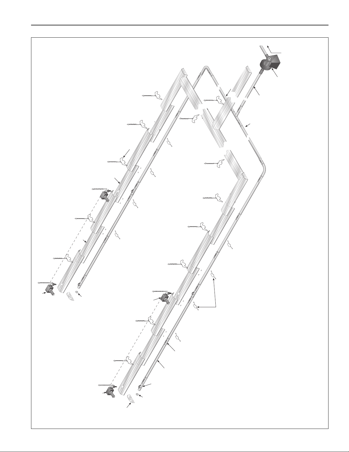
FIGURE 1: Assembly Overview (Two Branch System Shown)
Pump
End
Vent
Combustion
Chamber
End Burner
Radiant
Tube
Coupling
Reflector
End Cap
Reflector
Support
Burner
Tube &
Reflector
Hanger
Reflector
Reflector
with Hole
End Vent
Exhaust to
Outside
Shared Tailpipe
End Burner
Tailpipe
Tailpipe
1. Radiant tubing between burners, and 20-50' (6-15 m)
downstream of the last burner is normally hot rolled steel or
heat-treated aluminized steel. All tailpipe tubing must be por-
celain coated steel or heat-treated aluminized steel.
2. Damper couplings are required when layout has unequal
branches. Unequal branches are achieved by unequal
geometry, burner quantity or burner firing rates.
3. Plain couplings are used to connect combustion chambers
to radiant tubing and radiant tubing to tailpipe tubing. All
tailpipe couplings must be lined.
SECTION 2: THE CRV-SERIES SYS TEM
3

CRV-SERIES DESIGN MANUAL
2.3 Fuel Savings and Comfort
Space heating can be accomplished with less input
capacity when a radiant heating system is utilized,
rather than with a conventional convective heating
system. Why is this so?
A conventional, convective heating system, such as a
unit heater or central furnace works by heating the air,
which then indirectly heats the area and
occupants. CRV-Series utilizes infrared energy to heat
objects, people and surfaces directly, not the air. The
warm objects and floor create a heat reservoir, which
then re-radiates to the surroundings and also heats
the air by convection.
The radiant energy received by the occupants, directly
from the heater or indirectly from the
surroundings via re-radiation, serves to increase the
mean radiant temperature (MRT) of the space. In a
manner similar to direct sunlight, the increased MRT
allows the occupant to perceive a comfort condition at
a reduced air temperature. The resulting reduced air
temperature within the space provides the
following fuel-saving advantages:
• Reduced stratification of air in the space.
• Reduced transmission heat loss due to lower temperature inside than assumed design
condition.
• Redu
ced air change heat loss, to the extent that
exfiltration through cracks or openings near the
roof will be decreased because of decreased
stack effect.
• Decreases the actual degree days experienced.
4
SECTION 3: CLEARANCES TO COMBUSTIBLES
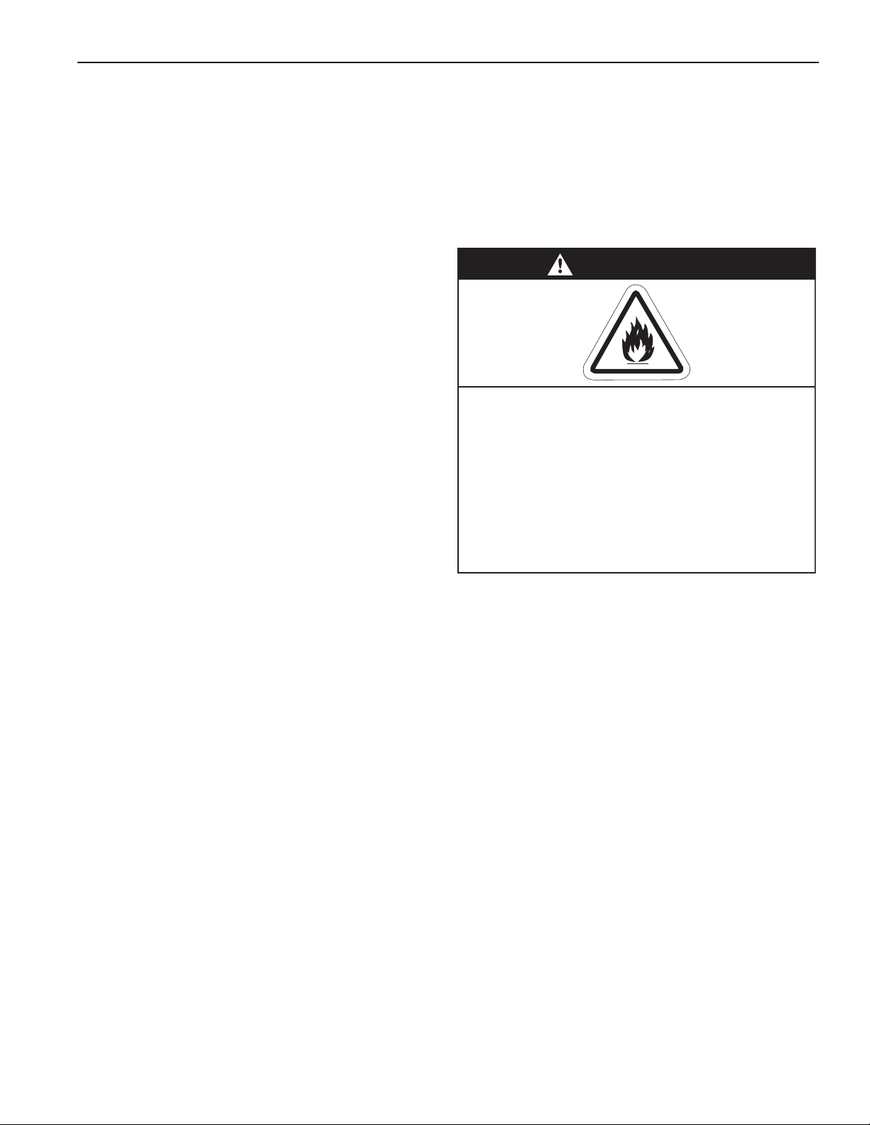
WARNING
Fire Hazard
Keep all flammable objects, liquids and
vapors the minimum required clearances to
combustibles away from heater.
Some objects will catch fire or explode when
placed close to heater.
Failure to follow these instructions can result
in death, injury or property damage.
3.1 Required Clearances to Combustibles
Clearances are the required distances that combusti-
ble objects must be away from the heater to prevent
serious fire hazards. Combustibles are materials,
which may catch on fire and include common items
such as wood, paper, rubber, fabric, etc. Maintain
clearances to combustibles at all times for safety.
Clearances for all heater models are located on the
burner assembly and on Page 6, Figure 3 through
Page 8, Figure 10 in this manual. Check the clear-
ances on each burner for the model heater being
installed to make sure the product is suitable for your
application and the clearances are maintained. Read
and follow the safety guidelines below:
• Keep gasoline or other combustible materials
including flammable objects, liquids, dust or
vapors away from this heater or any other appli-
ance.
SECTION 3: CLEARANCES TO C OMBUSTIBLES
• Hang heater in accordance to the minimum sus-
pension requirements.
• If the radiant tubes must pass through the building
structure, be sure that adequate sleeving and fire
stop is installed to prevent scorching and/or fire
hazard.
•
The stated clearances to combustibles represents
a surface temperature of 90° F (32° C) above
room temperature. Building materials with a low
heat tolerance (such as plastics, vinyl siding, canvas, tri-ply, etc) may be subject to degradation at
lower temperatures. It is the installer’s responsibility to assure that adjacent materials are protected
from degradation.
• Maintain clearances from heat sensitive
equipment and workstations.
• Maintain clearances from vehicles parked below
the heater.
• Maintain clearances from swinging and overhead
doors, overhead cranes, vehicle lifts, partitions,
storage racks, hoists, building construction, etc.
• In locations used for the storage of combustible
materials, signs must be posted to specify the
maximum permissible stacking height to maintain
required clearances from the heater to the combustibles. Signs must be posted adjacent to the
heater thermostat. In the absence of a thermostat, signs must be posted in a conspicuous location.
• Consult local Fire Marshal, Fire Insurance Carrier
or other authorities for approval of proposed
installation when there is a possibility of exposure
to combustible airborne materials or vapors.
5
CRV-SERIES DESIGN MANUAL
B
C
D
A
A
B
C
D
A
B
C
D
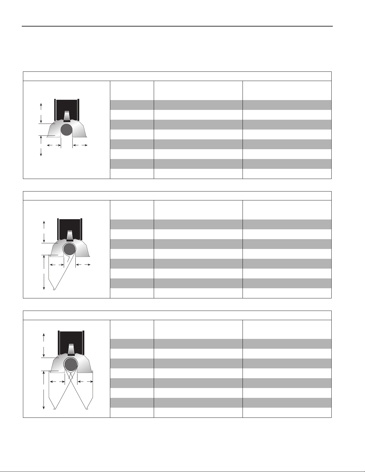
NOTE: 1. All dimensions are from the surfaces of all tubes, couplings, elbows, tees and crosses.
2. Clearances B, C and D can be reduced by 50% after 25' (7.5 m) of tubing downstream from
where the combustion chamber and the tube connect.
FIGURE 2: STANDARD REFLECTOR
Model A B C D A B C D
CRV-B-2 4 20 48 20 11 51 122 51
CRV-B-4 4 20 48 20 11 51 122 51
CRV-B-6 4 20 48 20 11 51 122 51
CRV-B-8 4 20 48 20 11 51 122 51
CRV-B-9 4 36 60 36 11 92 153 92
CRV-B-10 4 366036119215392
CRV-B-12 4 36 60 36 11 92 153 92
CRV-B-12A 4 36 60 36 11 92 153 92
.
(inches) (centimeters)
FIGURE 3: ONE SIDE REFLECTOR
(inches) (centimeters)
Model A B CDABCD
CRV-B-2 4 12 56 20 11 31 143 51
CRV-B-4 4 12 56 20 11 31 143 51
CRV-B-6 4 12 56 20 11 31 143 51
CRV-B-8 4 12 56 20 11 31 143 51
CRV-B-9 4 12 60 42 11 31 153 107
CRV-B-10 4 12 60 42 11 31 153 107
CRV-B-12 4 12 60 42 11 31 153 107
CRV-B-12A 4 12 60 42 11 31 153 107
FIGURE 4: TWO SIDE REFLECTORS
(inches) (centimeters)
Model A B CDABCD
CRV-B-2 4 12 56 12 11 31 143 31
CRV-B-4 4 12 56 12 11 31 143 31
CRV-B-6 4 12 56 12 11 31 143 31
CRV-B-8 4 12 56 12 11 31 143 31
CRV-B-9 4 12 60 12 11 31 153 31
CRV-B-10 4 12 60 12 11 31 153 31
CRV-B-12 4 12 60 12 11 31 153 31
CRV-B-12A 4 12 60 12 11 31 153 31
6
 Loading...