


FOR YOUR SAFETY |
|
|
|
||||
If you smell gas: |
|
|
|
||||
® |
|||||||
1. |
Open windows. |
||||||
2. |
DO NOT try to light any appliance. |
||||||
3. |
DO NOT use electrical switches. |
|
|
|
|||
4. |
DO NOT use any telephone in |
|
|
|
|||
|
your building. |
|
|
|
|||
5. |
Leave the building. |
|
|
|
|||
6. |
Immediately call your local gas |
Gas-Fired, Low-Intensity |
|||||
|
supplier after leaving the building. |
||||||
|
Follow the gas supplier’s |
||||||
|
|
|
|
||||
|
instructions. |
|
Infrared Heaters for |
||||
|
supplier, call the Fire Department. |
|
|||||
7. |
If you cannot reach your gas |
|
|
|
|||
|
|
|
|
Residential Garages and |
|||
|
WARNING |
||||||
|
|||||||
|
|
|
|
Light Industrial/Commercial |
|||
|
|
|
|
|
|
Applications |
|
|
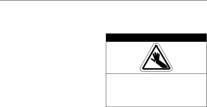
Fire Hazard |
|
Installation, Operation & |
||||
Do not store or use gasoline or other |
|
|
Service Manual |
||||
flammable vapors and liquids in the |
|
|
|||||
vicinity of this or any other appliance. |
|
|
|
||||
Some objects will catch fire or explode |
|
|
CGTH-30 |
||||
when placed close to heater. |
|
|
|||||
Failure to follow these instructions can |
|
|
CGTH-40 |
||||
result in death, injury or property |
|
|
|||||
damage. |
|
|
CGTH-50 |
||||
|
|
|
|
|
|
||
|
|
|
|
|
|
|
|
WARNING |
Installer |
|
|
||
Improper installation, adjustment, alteration, service |
Please take the time to read and understand |
|
these instructions prior to any installation. |
||
or maintenance can result in death, injury or property |
||
Installer must give a copy of this manual to the owner. |
||
damage. Read the Installation, Operation and Service |
||
|
||
Manual thoroughly before installing or servicing |
Owner |
|
this equipment. |
||
|
||
Installation must be done by a contractor qualified |
Keep this manual in a safe place in order to provide |
|
your serviceman with necessary information. |
||
in the installation and service of gas-fired heating |
|
|
equipment or your gas supplier. |
|
|
|
Roberts-Gordon, LLC |
|
|
1250 William Street |
|
|
P.O. Box 44 |
|
|
Buffalo, New York 14240-0044 |
|
|
Telephone: 716.852.4400 |
|
|
Fax: 716.852.0854 |
|
|
Toll Free: 800.828.7450 |
|
Quality in Any Language™ |
www.rg-inc.com |
|
© Copyright 2005 Roberts-Gordon |
P/N 180100NA Rev. G 11/05 |

TABLE OF CONTENTS |
|
|
SECTION 1: Before You Begin ............................................... |
1 |
|
1.1 Read This Manual ........................................................ |
1 |
|
1.2 Questions, Comments or Suggestions......................... |
1 |
|
SECTION 2: Introduction........................................................ |
2 |
|
2.1 |
About Roberts-Gordon ................................................ |
2 |
2.2 |
About the Heater.......................................................... |
2 |
2.3 |
Unpacking the Heater .................................................. |
2 |
2.4 |
Carton Contents of Heaters with Galvanized Venting .. |
3 |
2.5 |
Carton Contents of Heaters with Cox Geelen Venting . 4 |
|
2.6 |
Available Accessories for Galvanized Vent .................. |
5 |
2.7 |
Available Accessories for Cox Geelen Vent ................. |
6 |
2.8 |
Components Identification ........................................... |
7 |
2.9 |
Technical Specifications............................................... |
8 |
2.10 Where Can the Heater Be Installed? ......................... |
9 |
|
2.11 Where Can't the Heater Be Installed? ........................ |
9 |
|
2.12 Installer's Responsibility............................................. |
9 |
|
SECTION 3: Planning............................................................ |
10 |
|
3.1 |
General ...................................................................... |
10 |
3.2 |
Gas Service Requirements........................................ |
10 |
3.3 |
Electrical Service Requirements................................ |
10 |
3.4 |
Venting Requirements................................................ |
11 |
3.5 |
Non-Residential Installations ..................................... |
11 |
SECTION 4: Installation........................................................ |
13 |
|
4.1 |
Safety Equipment ...................................................... |
13 |
4.2 |
Installation Tools ........................................................ |
13 |
4.3 |
Installation Materials .................................................. |
13 |
4.4 |
Choose Location for Heater....................................... |
13 |
4.5 |
General Venting Guidelines ....................................... |
14 |
4.6 |
Required Safe Distances from Combustibles............. |
15 |
4.7 |
Hang the Heater ........................................................ |
17 |
4.8 |
Remove Shipping Screw from Control Housing Door 17 |
|
4.9 |
Heater Assembly ....................................................... |
17 |
4.10 Typical Installation.................................................... |
18 |
|
4.11 Heater Orientation.................................................... |
18 |
|
4.12 Horizontal Installation............................................... |
18 |
|
4.13 45° Tilted Installation................................................ |
19 |
|
4.14 Grille Installation (for Select Models Only)............... |
20 |
|
SECTION 5: Venting Installation.......................................... |
21 |
|
5.1 |
General Venting Requirements.................................. |
21 |
5.2 |
Install Galvanized Collar ............................................ |
21 |
5.3 |
Galvanized Horizontal Venting ................................... |
22 |
5.4 |
Cox Geelen Horizontal Venting .................................. |
27 |
5.5 |
Cox Geelen Vertical Venting ...................................... |
29 |
SECTION 6: Electrical Service Installation ......................... |
31 |
|
6.1 |
System Requirements................................................ |
31 |
6.2 |
Grounding .................................................................. |
31 |
6.3 |
Important Notes ......................................................... |
31 |
6.4 |
Thermostat Placement .............................................. |
31 |
6.5 |
Thermostat Installation .............................................. |
31 |
SECTION 7: Gas Service Installation .................................. |
33 |
|
7.1 Install Gas Supply Lines............................................. |
33 |
|
SECTION 8: Operation.......................................................... |
34 |
|
8.1 |
Operating Instructions ............................................... |
34 |
8.2 |
To Turn Off Gas To Heater ......................................... |
34 |
8.3 |
Sequence of Operation.............................................. |
34 |
8.4 |
Testing ....................................................................... |
34 |
SECTION 9: Troubleshooting............................................... |
36 |
|
9.1 |
General...................................................................... |
36 |
SECTION 10: Maintenance ................................................... |
41 |
|
10.1 Pre-Season Maintenance......................................... |
41 |
|
SECTION 11: Wiring Diagrams............................................. |
42 |
|
11.1 Connection Diagram................................................. |
42 |
|
11.2 Ladder Diagram........................................................ |
43 |
|
SECTION 12: Replacement Parts ........................................ |
44 |
|
12.1 Illustrated Parts List for Burner ................................ |
44 |
|
12.2 lllustrated Parts List for Tube and Reflector ............. |
46 |
|
12.3 Replacement Parts List for Tube & Reflector ........... |
46 |
|
SECTION 13: The ROBERTS GORDON® CARIBE® LIMITED |
||
Warranty................................................................................. |
47 |
|
© 2005 


All rights reserved. No part of this work covered by the copyrights herein may be reproduced or copied in any form or by any means - graphic, electronic, or mechanical, including photocopying, recording, taping or information storage and retrieval systems - without the written permission of Roberts-Gordon.
Printed in the U.S.A.

TABLE OF FIGURES |
|
Figure 1: Components Identification ......................................... |
7 |
Figure 2: Specifications............................................................. |
8 |
Figure 3: Balanced Flue.......................................................... |
11 |
Figure 4: Horizontal Installations............................................. |
16 |
Figure 5: 45° Tilted Installations.............................................. |
16 |
Figure 6: Shipping Screw........................................................ |
17 |
Figure 7: Suspension Details.................................................. |
17 |
Figure 8: Heater Assembly ..................................................... |
17 |
Figure 9: Typical Installation.................................................... |
18 |
Figure 10: Horizontal Installation............................................. |
19 |
Figure 11: 45° Tilted Installation .............................................. |
19 |
Figure 12: Silicone Cap Installation ........................................ |
20 |
Figure 13: Grille End Cap Installation...................................... |
20 |
Figure 14: Reflector and Grille ................................................ |
20 |
Figure 15: Rear View .............................................................. |
21 |
Figure 16: Horizontal Installation Side View............................ |
23 |
Figure 17: Bird Screen Installation.......................................... |
23 |
Figure 18: Horizontal Installation Top View ............................ |
24 |
Figure 19: Elbow Assembly End View .................................... |
24 |
Figure 20: Elbow Assembly Cross Section View .................... |
24 |
Figure 21: Elbow Assembly .................................................... |
25 |
Figure 22: Elbow Assembly for Vent Collar ............................ |
25 |
Figure 23: Vent Collar and 5" Vent Attachment ...................... |
25 |
Figure 24: Assembly Overview ............................................... |
26 |
Figure 25: Horizontal Installation Side View |
|
Cox Geelen Venting ............................................... |
27 |
Figure 26: Flue Collar and Adapter......................................... |
28 |
Figure 27: Horizontal Venting Configurations ......................... |
28 |
Figure 28: Vertical Venting Configurations ............................. |
29 |
Figure 29: Vent Clamp............................................................ |
30 |
Figure 30: Thermostat Installation .......................................... |
31 |
Figure 31: Thermostat Installation Rear View......................... |
32 |
Figure 32: Gas Supply Lines................................................... |
33 |
Figure 33: Pressure Testing.................................................... |
35 |
Figure 34: Manometer Reading .............................................. |
38 |
Figure 35: Connection Diagram .............................................. |
42 |
Figure 36: Ladder Diagram .................................................... |
43 |
Figure 37: Illustrated Parts List ............................................... |
44 |
Figure 38: Tube and Reflector................................................. |
46 |

SECTION 1: BEFORE YOU BEGIN
SECTION 1: BEFORE YOU BEGIN
1.1 Read This Manual
Read this manual carefully before installing or servicing this equipment. Improper installation, servicing or maintenance can result in death, injury or property damage. Check the required safe distances from combustibles given on the outside of each burner to make sure that the product is suitable for your application. The required safe distances from combustibles are also found on Pages 15 and 16 of this manual. Installer must be a contractor qualified in the installation and service of gas-fired heating equipment. After the installation is complete, check product operation as provided in these instructions.
1.2 Questions, Comments or Suggestions
Please direct any questions, comments or suggestions to:
Roberts-Gordon, LLC
1250 William Street P.O. Box 44
Buffalo, New York 14240-0044 Telephone: 716.852.4400 Fax: 716.852.0854
Toll Free: 800.828.7450
1
CGTH INSTALLATION, OPERATION AND SERVICE MANUAL
SECTION 2: INTRODUCTION
2.1 About Roberts-Gordon
Roberts-Gordon pioneered low-intensity infrared heating systems in 1962 with the introduction of its revolutionary, custom-engineered CORAYVAC® system. After more than 40 years of infrared expertise in commercial and industrial applications, Roberts-Gor- don now offers the CGTH-Series heater for use in residential garages and light industrial/commercial applications.
2.2 About the Heater
The CGTH-Series is a factory-assembled, gas-fired, low-intensity heating system that incorporates a balanced flue. The system has been designed for easy installation and will provide years of economical operation and trouble-free service. Not only is infrared heat efficient, it also provides the most comfortable conditions in open areas, such as garages.
Gas-Fired means it uses clean-burning natural or LP gas.
Low-Intensity means that the radiant surface of the tube does not glow red. Instead, it operates at a lower temperature (less than 1000°F) and radiates energy at a lower intensity per square foot of radiating surface. The lower temperature and intensity levels are within a range that is most effective in establishing and maintaining personal comfort levels. An aluminum reflector directs the radiant energy downward to the occupied area.
Balanced Flue means that the burner draws combustion air from outdoors and exhausts the products of combustion, also to the outdoors, through a shared opening. This is accomplished through two concentric tubes.
Radiant refers to the energy radiated by the CGTHSeries heater. Because the energy is in the form of infrared rays, it does not directly heat the air. Instead, the rays heat objects such as the floor, cars, machines and people. The warm objects, in turn, heat the air.
These combined features are the key to the exceptional comfort and fuel efficiency provided by the CGTH-Series heater.
2.3 Unpacking the Heater
2.3.1 Manpower Requirements
To prevent personal injury and damage to the heater, two persons will be required to remove the heater from the carton. Both ends of the heater should be
lifted from the carton at the same time. The burner should be lifted by gripping the bottom. The reflector of the heater should be lifted using the hanger.
2.3.2 Safety
 WARNING
Cut Hazard
Wear protective gloves when handling aluminum reflectors.
Edges are sharp.
Failure to follow these instructions can result in injury.
Thin sheet metal parts, such as the reflector portion of the heater and the various venting components, have sharp edges. To prevent injury, the use of work gloves is recommended. The use of gloves will also prevent the transfer of body oils from the hands to the surface of the reflector.
2

SECTION 2: INTRODUCTION
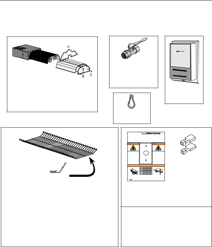
2.4 Carton Contents of Heaters with Galvanized Venting
Please check the cartons. It should contain the items shown on this page. Contact your ROBERTS GORDON® independent distributor if any items are missing.
(*) Additional package included with select models; also available as an accessory. See Page 5.
Heater Assembly:
A
 B C
B C
CGTH-30; CGTH-40; CGTH-50
A.) (1) Hanger P/N 08080000
B.) (1) Reflector End Cap P/N 02750800 C.) (4) U-Clips P/N 91107720
(1) Vent Termination |
|
(1) Bird Screen |
P/N 08031001 |
|
P/N 08036000 |
|
|
|
* 5' (125 mm) Balanced Flue Vent package (P/N 08039000) includes:
(1)3" (80 mm) Flue Pipe 66"(168 cm) Long
P/N 08035000
(1)5" (125 mm) Vent Pipe 60" (1520 mm) Long
P/N 90502800
(1)3/8" (10 mm) Manual Gas Shut-off Valve P/N 90100200
°F |
l |
40 |
50 |
60 |
70 |
||
°C |
l |
l |
|
l |
|||
|
5 |
10 15 |
20 |
l |
|||
OFF |
|
|
|
||||
FRONT
(1) Thermostat
P/N 90409702
(1) Flue Collar
P/N 91911701
(4) Snap Hooks
P/N 91903300
Grille (P/N 08050001)
Grille End Cap (P/N 08050002)
Side View
Protective Grille Kits - Included with select models. Also available as an accessory under kit part numbers.
CGTH-30 Kit (P/N 08051000) includes:
(1)Grille End Cap P/N 08050002
(2)Grille without End Cap P/N 08050001
(2)Silicone Cap P/N 91915951-6P
CGTH-40 and CGTH-50 Kit (P/N 08051001) includes:
(3) Grille without End Cap P/N 08050001
(1) Grille End Cap P/N 08050002
(3) Silicone Cap P/N 91915951-6P
CGTH-Series by 


This thermostat controls your overhead tube heater. Keep burner, control compartment and reflector clean. Read your CGTH-Series Use and Care Manual (P/N 180101NA or GH80101NA) and follow all Safety Requirements which include checking your heater monthly. Installation, Service and Annual Inspection must be done by a contractor qualified in the installation and service of gas-fired heating equipment. Please call (716) 852-4400 (USA) or (905) 945-5403 (Canada) if you need a manual or have questions.
Ce thermostat commande votre radiateur. Gardez le module de contrôle et le reflécteur propres. Lisez le manuel d’utilisation et d’entretien CGTH-Series (P/N 180101NA ou GH80101NA) et respectez tous les conseils de sécurité, notamment le contrôle mensuel du radiateur. L’installation, l'entretien et l’inspection annuelle doivent être effectués par un agent agréé. Veuillez nous contactez au 716-852-4400 (USA) ou au 905-945-5403 (Canada) pour toutes questions ou demandes de manuel.
 WARNING
 ATTENTION
|
|
|
|
MOUNT |
|
|
|
|
|
|||
|
|
|
THERMOSTAT |
|
|
|
|
|||||
|
|
|
|
HERE |
|
|
|
|
|
|
||
Fire Hazard |
|
|
|
|
|
|
|
|
Risque d'incendie |
|||
Some objects will catch fire or |
|
|
|
|
|
|
|
Certains objets placés près du |
||||
explode when placed close to |
|
|
|
|
|
|
|
radiateur peuvent s'enflammer ou |
||||
heater. |
|
|
|
|
|
|
|
|
|
exploser. |
|
|
Keep all flammable objects, |
MONTER LE |
|
Tenir tous les objets, iquides et |
|||||||||
liquids and vapors the required |
|
vapeurs inflammables à la |
||||||||||
safe distances away from heater. |
THERMOSTAT ICI |
distance de sécurité requise du |
||||||||||
Keep children, clothing and |
|
|
|
|
|
|
|
radiateur. |
|
|
||
furniture away from the heater. |
|
|
|
|
|
|
|
Surveiffer les enfants. Gardes les |
||||
|
|
|
|
|
|
|
|
|
|
vêtements, les meubles loin de |
||
Failure to follow these |
|
|
|
|
|
|
|
|
l'appareil. |
|
|
|
instructions will result in death, |
|
|
|
|
|
|
|
|
|
|
||
injury or property damage. |
|
|
|
|
|
|
|
Le non-respect de ces consignes |
||||
|
|
|
|
|
|
|
|
|
|
peut causer dommage au matériel. |
||
|
|
Required Safe Distances from Combustibles |
|
|
||||||||
|
Distances de Dégagement par Rapport aux Combustibles |
|
|
|||||||||
Horizontal Mount |
|
Model |
A |
B |
C |
D |
E |
F |
45° Mount |
|
||
Montage Horizontal |
CGTH-30 |
4 |
16 |
36 |
28 |
34 |
6 |
Montage à 45° |
||||
|
|
|
CGTH-40 |
4 |
18 |
48 |
30 |
34 |
6 |
24" Min. (61 cm) |
|
A |
|
|
|
CGTH-50 |
4 |
20 |
48 |
32 |
36 |
6 |
|
|
|
|
A |
|
Modèle |
A |
B |
C |
D |
E |
F |
D |
|
A |
Rating Tag |
|
B |
CGTH-30 |
11 |
41 |
92 |
72 |
87 |
16 |
|
|
F |
Éttiquette de |
C |
CGTH-40 |
11 |
46 |
122 |
77 |
87 |
16 |
|
|
||
Classement |
F |
|
E |
|
||||||||
|
B |
|
CGTH-50 |
11 |
51 |
122 |
82 |
92 |
16 |
|
|
|
NOTES: 1. All dimensions are from the reflector. |
|
|
NOTES: |
1. Toutes les dimensions sont mesurées à partir du réflecteur. |
||||||||
2. Black numerals are in inches. Orange numerals are in |
|
|
|
2. Les chiffres noirs sont en pouces. Les chiffres oranges |
||||||||
centimeters. |
|
|
|
|
|
|
sont en centimètres. |
|
|
|||
3. Know your model number. Model number is found on the |
|
|
3. Vous devrez connaître le numéro de votre modèle. Il se |
|||||||||
rating tag. (See horizontal mount drawing for location of |
|
|
|
trouve sur l’étiquette de classement. (Voir le dessin du |
||||||||
rating tag). |
|
|
|
|
|
|
montage horizontal pour l’emplacement de l’étiquette de |
|||||
|
|
|
|
|
|
|
|
classement). |
|
|
|
|
© |
|
www.rg-inc.com |
|
|
Printed in U.S.A./Imprimé aux Etats-Unis |
P/N |
91037903 Rev F |
|||||
(2) Female Terminals to connect thermostat wire P/N 91317300
(1)Thermostat Tag P/N 91037903
(3)Vent Collar Mounting Screws to attach vent collar to heater
P/N 94118106
Documents:
(1)Installation Manual P/N 180100NA
(1)Use and Care Manual P/N180101NA
(1)Owner Warranty Registration Card: P/N CGTHWCNA
3
CGTH INSTALLATION, OPERATION AND SERVICE MANUAL
2.5 Carton Contents of Heaters with Cox Geelen Venting
Please check the cartons. It should contain the items shown on this page. Contact your ROBERTS GORDON® independent distributor if any items are missing.
Heater Assembly: |
|
|
|
|
|
|
|
|
|
|
(1) 3/8" (10 mm) |
|
|
|
|
|
|
|
|
|
Manual Gas |
°F |
l |
40 |
50 |
60 |
70 |
||
|
Shut-off Valve |
° |
l |
l |
|||||
|
|
|
l |
|
l |
||||
|
|
5 |
|
|
|
||||
|
C |
|
10 15 |
|
20 |
|
|||
|
OFF |
|
|
|
|
||||
|
|
|
|
|
|
||||
CGTH-30; CGTH-40; CGTH-50 |
P/N 90100200 |
|
|
|
|
|
|
|
|
|
|
|
FRONT |
||||||
|
|
|
|
||||||
A.) (1) Hanger P/N 08080000 |
|
(1) Thermostat |
|||||||
B.) (1) Reflector End Cap P/N 02750800 |
|
P/N 90409702 |
|||||||
C.) (4) U-Clips P/N 91107720 |
|
|
|
|
|
|
|
|
|
|
(4) Snap Hooks |
|
|
|
|
|
|
|
|
|
P/N 91903300 |
|
|
|
|
|
|
|
|
Grille (P/N 08050001) |
CGTH-Series by |
|
|
|
|
|
|
|
|
945-5403 (Canada) if you need a manual or have questions. |
|
|
|
|
|
|
|
|
|
|
This thermostat controls your overhead tube heater. Keep burner, control compartment and reflector clean. Read |
|
|
|
|
|
|
|
|
|
your CGTH-Series Use and Care Manual (P/N 180101NA or GH80101NA) and follow all Safety Requirements which |
|
|
|
|
|
|
|
|
|
include checking your heater monthly. Installation, Service and Annual Inspection must be done by a contractor |
|
|
|
|
|
|
|
|
|
qualified in the installation and service of gas-fired heating equipment. Please call (716) 852-4400 (USA) or (905) |
|
|
|
|
|
|
|
|
|
Ce thermostat commande votre radiateur. Gardez le module de contrôle et le reflécteur propres. Lisez le manuel |
|
|
|
|
|
|
|
|
|
d’utilisation et d’entretien CGTH-Series (P/N 180101NA ou GH80101NA) et respectez tous les conseils de sécurité, |
|
|
|
|
|
|
|
|
|
notamment le contrôle mensuel du radiateur. L’installation, l'entretien et l’inspection annuelle doivent être effectués |
|
|
|
|
|
|
|
|
|
par un agent agréé. Veuillez nous contactez au 716-852-4400 (USA) ou au 905-945-5403 (Canada) pour toutes |
|
|
|
|
|
|
|
|
|
questions ou demandes de manuel. |
|
|
|
|
|
|
|
|
|
WARNING |
ATTENTION |
|
|
|
|
|
|
|
|
|
|
|
MOUNT |
|
|
|
|
|
|
||||
|
|
|
THERMOSTAT |
|
|
|
|
|
||||||
|
|
|
|
HERE |
|
|
|
|
|
|
|
|||
|
Fire Hazard |
|
|
|
|
|
|
|
|
Risque d'incendie |
|
|||
|
Some objects will catch fire or |
|
|
|
|
|
|
|
Certains objets placés près du |
|
||||
|
explode when placed close to |
|
|
|
|
|
|
|
radiateur peuvent s'enflammer ou |
|
||||
|
heater. |
|
|
|
|
|
|
|
|
exploser. |
|
|
||
|
Keep all flammable objects, |
MONTER LE |
|
Tenir tous les objets, iquides et |
(2) Female Terminals |
|||||||||
|
liquids and vapors the required |
|
vapeurs inflammables à la |
|||||||||||
|
safe distances away from heater. |
THERMOSTAT ICI |
vêtements, les meubles loin de |
|||||||||||
|
distance de sécurité requise du |
|
||||||||||||
|
Keep children, clothing and |
|
|
|
|
|
|
|
radiateur. |
|
|
|||
|
furniture away from the heater. |
|
|
|
|
|
|
|
Surveiffer les enfants. Gardes les |
|
||||
Grille End Cap |
Failure to follow these |
|
|
|
|
|
|
|
|
l'appareil. |
|
|
||
instructions will result in death, |
|
|
|
|
|
|
|
|
|
|
to connect |
|||
injury or property damage. |
|
|
|
|
|
|
|
Le non-respect de ces consignes |
||||||
|
|
|
|
|
|
|
|
|
peut causer dommage au matériel. |
|||||
|
Required Safe Distances from Combustibles |
Min. (61 cm) |
A |
|||||||||||
(P/N 08050002) |
|
|
CGTH-40 |
4 |
18 |
48 |
30 |
34 |
6 |
24" |
||||
|
Distances de Dégagement par Rapport aux Combustibles |
|
||||||||||||
|
Horizontal Mount |
|
Model |
A |
B |
C |
D |
E |
F |
|
45° Mount |
|
thermostat wire |
|
|
Montage Horizontal |
CGTH-30 |
4 |
16 |
36 |
28 |
34 |
6 |
|
Montage à 45° |
||||
|
Rating Tag |
|
CGTH-30 |
11 |
41 |
92 |
72 |
87 |
16 |
|
D |
A |
||
|
|
|
CGTH-50 |
4 |
20 |
48 |
32 |
36 |
6 |
|
|
|
|
|
|
A |
|
Modèle |
A |
B |
C |
D |
E |
F |
|
|
|
|
|
|
Éttiquette de |
B |
CGTH-40 |
11 |
46 |
122 |
77 |
87 |
16 |
|
|
F |
|
|
|
Classement C |
F |
|
E |
|
P/N 91317300 |
||||||||
Side View |
B |
|
CGTH-50 |
11 |
51 |
122 |
82 |
92 |
16 |
|
|
|
||
rating tag). |
|
|
|
|
|
|
montage horizontal pour l’emplacement de l’étiquette de |
|||||||
|
NOTES: 1. All dimensions are from the reflector. |
|
|
NOTES: |
1. Toutes les dimensions sont mesurées à partir du réflecteur. |
|
||||||||
|
2. Black numerals are in inches. Orange numerals are in |
|
|
|
2. Les chiffres noirs sont en pouces. Les chiffres oranges |
|
||||||||
|
centimeters. |
|
|
|
|
|
|
sont en centimètres. |
|
|
|
|||
|
3. Know your model number. Model number is found on the |
|
|
3. Vous devrez connaître le numéro de votre modèle. Il se |
|
|||||||||
|
rating tag. (See horizontal mount drawing for location of |
|
|
|
trouve sur l’étiquette de classement. (Voir le dessin du |
|
||||||||
|
|
|
|
|
|
|
|
classement). |
|
|
|
|||
|
© |
www.rg-inc.com |
|
|
Printed in U.S.A./Imprimé aux Etats-Unis |
P/N |
91037903 Rev F |
|
||||||
Protective Grille Kits - Included with select models. Also |
(1) Thermostat Tag P/N 91037903 |
|||||||||||||
available as an accessory under kit part numbers. |
|
(3) Vent Collar Mounting Screws |
||||||||||||
CGTH-30 Kit (P/N 08051000) includes: |
|
|||||||||||||
|
|
to attach vent collar to heater |
||||||||||||
(1) Grille End Cap P/N 08050002 |
|
|
|
|
|
|
|
|
|
P/N 94118106 |
||||
(2) Grille without End Cap P/N 08050001 |
|
|
|
|
|
|
|
|
|
|
Documents: |
|||
(2) Silicone Cap P/N 91915951-6P |
|
|
|
|
|
|
|
|
|
|
||||
(1) Installation Manual P/N 180100NA |
||||||||||||||
CGTH-40 and CGTH-50 Kit (P/N 08051001) includes: |
||||||||||||||
|
|
|
(1) Use and Care Manual |
|||||||||||
(3) Grille without End Cap P/N 08050001 |
|
|
|
|
|
|
|
|
|
P/N180101NA |
||||
(1) Grille End Cap P/N 08050002 |
(1) Owner Warranty Registration Card: |
|||||||||||||
(3) Silicone Cap P/N 91915951-6P |
|
|
|
|
|
|
|
|
|
P/N CGTHWCNA |
||||
4
SECTION 2: INTRODUCTION
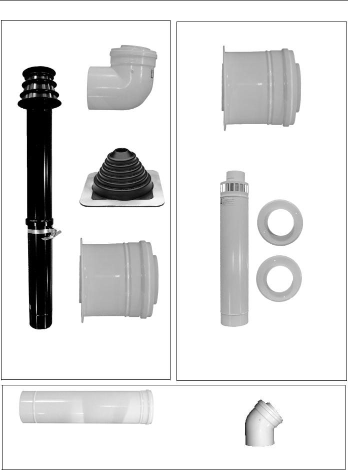
2.6 Available Accessories for Galvanized Vent
Vent Terminal Extension
P/N 08037000
5' (1524 mm) Balanced Flue Vent |
(P/N 08039000) includes: |
(1) 5" (125 mm) Vent Pipe - 60" |
P/N 90502800 |
(1) 3" (80 mm) Flue Pipe - 66" |
P/N 08035000 |
Tjernlund Wall Vent
P/N 08033000
5" (125 mm)
Diameter Elbow 1" (25 mm) Diameter Spring
6" (152 mm)
|
|
3" (80 mm) |
2.75" (57 mm) |
Diameter Elbow |
|
|
||
90° Elbow Kit (P/N 08038000) includes:
(1) 5" (125 mm) Diameter Elbow P/N 90503000
(1) 3" (80 mm) Diameter Elbow P/N 90503100
(1) Coil Spring Spacer P/N 90503200
5
CGTH INSTALLATION, OPERATION AND SERVICE MANUAL
2.7 Available Accessories for Cox Geelen Vent
Roof Venting Kit (P/N 08032100) includes:
(1) Elbow 90°
P/N 90506001
(1) Storm Collar
P/N 90506015
(1) Burner/Vent Adapter
(1) Roof Terminal P/N 90506012
50.5” (1283 mm)
P/N 90506008
Wall Venting Kit (P/N 08032200) includes:
(1) Burner/Vent Adapter P/N 90506012
(1) Wall Terminal 25” (635 mm)
with wall plate (P/N 90506011) includes:
(4)Screws P/N 94118106
(2)Wall Plates P/N 90506013
Concentric Flue 250 mm = 10” P/N 90506003 |
|
Concentric Flue 500 mm = 20” P/N 90506004 |
|
Concentric Flue 1000 mm = 39” P/N 90506005 |
Elbow 45° = 39” P/N 90506002 |
6

|
SECTION 2: INTRODUCTION |
2.8 Components Identification |
|
FIGURE 1: Components Identification |
|
|
Nipple 3/8” |
Vent Collar |
(10 mm) NPT |
Thermostat |
|
|
Connection |
Wall Termination Plate |
|
Venting |
Power |
|
|
Burner |
Cord |
|
|
Gas Line |
|
Front Fixed Hanger |
|
Manual Gas
Shut-off Valve
Service Door
Protective Grill
Reflector
Heat Exchanger
Rear Movable
 Hanger
CGTH-Series by 


This thermostat controls your overhead tube heater. Keep burner, control compartment and reflector clean. Read your CGTH-Series Use and Care Manual (P/N 180101NA or GH80101NA) and follow all Safety Requirements which include checking your heater monthly. Installation, Service and Annual Inspection must be done by a contractor qualified in the installation and service of gas-fired heating equipment. Please call (716) 852-4400 (USA) or (905) 945-5403 (Canada) if you need a manual or have questions.
Ce thermostat commande votre radiateur. Gardez le module de contrôle et le reflécteur propres. Lisez le manuel d’utilisation et d’entretien CGTH-Series (P/N 180101NA ou GH80101NA) et respectez tous les conseils de sécurité, notamment le contrôle mensuel du radiateur. L’installation, l'entretien et l’inspection annuelle doivent être effectués par un agent agréé. Veuillez nous contactez au 716-852-4400 (USA) ou au 905-945-5403 (Canada) pour toutes questions ou demandes de manuel.
 WARNING
 ATTENTION
|
|
|
|
MOUNT |
|
|
|
|
|
|||
|
|
|
THERMOSTAT |
|
|
|
|
|||||
|
|
|
|
HERE |
|
|
|
|
|
|
||
Fire Hazard |
|
|
|
|
|
|
|
|
Risque d'incendie |
|||
Some objects will catch fire or |
|
|
|
|
|
|
|
Certains objets placés près du |
||||
explode when placed close to |
|
|
|
|
|
|
|
radiateur peuvent s'enflammer ou |
||||
heater. |
|
|
|
|
|
|
|
|
|
exploser. |
|
|
Keep all flammable objects, |
MONTER LE |
|
Tenir tous les objets, iquides et |
|||||||||
liquids and vapors the required |
|
vapeurs inflammables à la |
||||||||||
safe distances away from heater. |
THERMOSTAT ICI |
distance de sécurité requise du |
||||||||||
Keep children, clothing and |
|
|
|
|
|
|
|
radiateur. |
|
|
||
furniture away from the heater. |
|
|
|
|
|
|
|
Surveiffer les enfants. Gardes les |
||||
|
|
|
|
|
|
|
|
|
|
vêtements, les meubles loin de |
||
Failure to follow these |
|
|
|
|
|
|
|
|
l'appareil. |
|
|
|
instructions will result in death, |
|
|
|
|
|
|
|
|
|
|
||
injury or property damage. |
|
|
|
|
|
|
|
Le non-respect de ces consignes |
||||
|
|
|
|
|
|
|
|
|
|
peut causer dommage au matériel. |
||
|
|
Required Safe Distances from Combustibles |
|
|
||||||||
|
Distances de Dégagement par Rapport aux Combustibles |
|
|
|||||||||
Horizontal Mount |
|
Model |
A |
B |
C |
D |
E |
F |
45° Mount |
|
||
Montage Horizontal |
CGTH-30 |
4 |
16 |
36 |
28 |
34 |
6 |
Montage à 45° |
||||
|
|
|
CGTH-40 |
4 |
18 |
48 |
30 |
34 |
6 |
24" Min. (61 cm) |
|
A |
|
|
|
CGTH-50 |
4 |
20 |
48 |
32 |
36 |
6 |
|
|
|
|
A |
|
Modèle |
A |
B |
C |
D |
E |
F |
D |
|
A |
Rating Tag |
|
B |
CGTH-30 |
11 |
41 |
92 |
72 |
87 |
16 |
|
|
F |
Éttiquette de |
C |
CGTH-40 |
11 |
46 |
122 |
77 |
87 |
16 |
|
|
||
Classement |
F |
|
E |
|
||||||||
|
B |
|
CGTH-50 |
11 |
51 |
122 |
82 |
92 |
16 |
|
|
|
NOTES: 1. All dimensions are from the reflector. |
|
|
NOTES: |
1. Toutes les dimensions sont mesurées à partir du réflecteur. |
||||||||
2. Black numerals are in inches. Orange numerals are in |
|
|
|
2. Les chiffres noirs sont en pouces. Les chiffres oranges |
||||||||
centimeters. |
|
|
|
|
|
|
sont en centimètres. |
|
|
|||
3. Know your model number. Model number is found on the |
|
|
3. Vous devrez connaître le numéro de votre modèle. Il se |
|||||||||
rating tag. (See horizontal mount drawing for location of |
|
|
|
trouve sur l’étiquette de classement. (Voir le dessin du |
||||||||
rating tag). |
|
|
|
|
|
|
montage horizontal pour l’emplacement de l’étiquette de |
|||||
|
|
|
|
|
|
|
|
classement). |
|
|
|
|
© |
|
www.rg-inc.com |
|
|
Printed in U.S.A./Imprimé aux Etats-Unis |
P/N |
91037903 Rev F |
|||||
Burner - Contains the electrical components (i.e. blower motor, power transformer, etc.) and gas distribution components (i.e. gas valve, etc.) that make the heater work. There are no owner serviceable items contained in this box.
Front Fixed Hanger - Provides rigid support and mounting surface for the reflector. Holes are provided in the upper corners of the bulkhead to accommodate suspension hardware required for installation of the heater.
Reflector - The reflector is made from formed aluminum and reflects the radiant energy downward to the space to be heated.
Heat Exchanger - A U-shaped tube through which the heated products of combustion pass.
Rear Movable Hanger - Provides support for the tube and reflector at the end that is furthest from the burner. The support may be moved (within limits) to accommodate hanging of the unit.
Service Door - To be removed only by a contractor qualified in the installation and service of gas-fired heating equipment or your gas supplier. Removal of
this service door provides access to the electrical and gas distribution components.
Gas Line - Must only be installed and serviced by a licensed contractor or gas fitter.
Wall Termination Plate - Placed on the outside wall over the venting.
Venting - Installer must properly exhaust the heater outside. The 5” outer duct carries fresh air to the burner. The 3” inner duct carries the products of combustion to the outside.
Thermostat - 24 Volt Thermostat mounted with Safety Tag.
Protective Grille - Included with select models. See Page 20, Section 4.14 for details.
Vent Collar - Accommodates a 5" (125 mm) diameter combustion air inlet duct that delivers fresh air to the burner. The fresh air enters the burner through the twelve equally spaced holes shown above. The 3" (80 mm) diameter hole in the center of the flue collar accommodates the venting duct that carries the products of combustion to be vented outdoors.
7
CGTH INSTALLATION, OPERATION AND SERVICE MANUAL
Nipple-3/8" (10 mm) NPT - Point at which the gas supply is connected to the heater.
Thermostat Connection - Two terminals to which the thermostat wires will be connected.
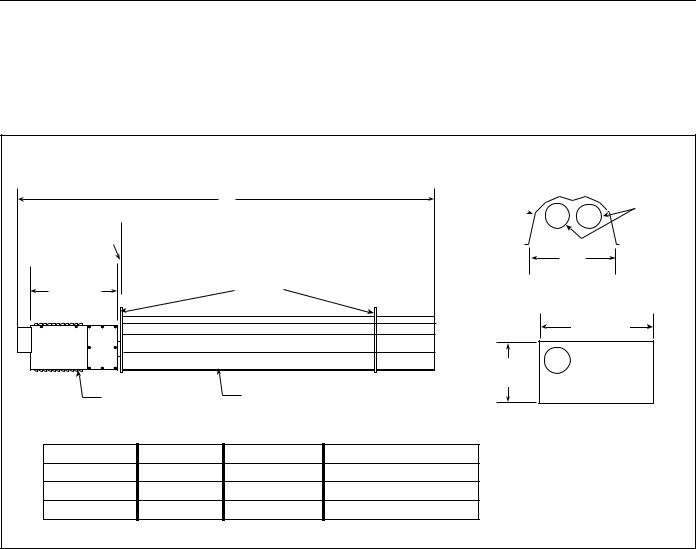
2.9 Technical Specifications
FIGURE 2: Specifications
Power Cord - Includes a three-prong plug that must be connected to a dedicated and properly grounded three-prong ceiling outlet.
|
- Side View - |
|
-End View- |
Heat |
|
|
A |
|
Reflector |
|
|
|
|
Exchanger |
|||
1" (25 mm) |
|
|
|
|
|
Maximum |
|
|
|
14” |
|
|
|
|
|
|
|
|
Suspension |
|
(356 mm) |
|
|
15" |
|
|
|
||
|
Points |
|
-Rear View- |
|
|
(381 mm) |
|
|
|
|
|
|
|
|
|
14" |
|
|
|
|
|
(356 mm) |
|
|
|
|
8.7" |
|
|
|
|
|
(220 mm) |
|
|
Burner |
|
Reflector |
|
|
|
|
Inputs and Dimensions |
|
|
|
|
Model No. |
BTU/hr |
Weight |
A |
|
|
CGTH-30 |
30,000 |
85 lbs. |
8'0" (2438 mm) |
|
|
CGTH-40 |
40,000 |
96 lbs. |
11'6" (3505 mm) |
|
|
CGTH-50 |
50,000 |
96 lbs. |
11'6" (3505 mm) |
|
|
HEATER SPECIFICATIONS
Electrical
Rating: 120 V, 60 Hz, 1 Ø, 1 A
Connection: 3 pin molded plug
Gas Inlet Connection
Connection: 3/8" Male NPT
Gas Inlet Pressure
Natural Gas:
Minimum:Inlet5.0" w.c. (12.4 mbar) Maximum:Inlet14.0" w.c. (34.8 mbar)
LP Gas (Propane): Minimum:Inlet11.0" w.c. (37.4 mbar) Maximum:Inlet14.0" w.c. (34.8 mbar)
Manifold Pressure
VENTING SPECIFICATIONS
Vent/Flue
Length:10' (3 m) (Maximum)
2' - 6" (1 m 15 cm) (Minimum)
Flue Pipe:3.0" (80 mm) diameter
Vent Pipe:5.0" (125 mm) diameter
Natural Gas: 3.5" w.c. (8.7 mbar)
LP Gas (Propane): 10.5" w.c. (26.1 mbar)
8

SECTION 2: INTRODUCTION
2.10 Where Can the Heater Be Installed?
The CGTH-Series heater is intended for installation in the following areas:
•Residential applications, such as:
-garages
-hobby greenhouses
-workshops
•Light industrial/commercial applications, such as:
-entranceways
-lobby areas
-lunch rooms
-aircraft hangars (See Page 11, Section 3.5.1 for restrictions)
-public garages (See Page 11, Section 3.5.2 for restrictions)
2.11Where Can't the Heater Be Installed?
The CGTH-Series heater is not intended for installation in the following areas:
•Residential living or sleeping areas
•Basements
Due to high temperatures, ensure that the heater area is kept clear of furniture, draperies, clothing or other combustible materials. Children and adults should be alerted to the hazard of high surface temperatures and should stay away to avoid burns and clothing ignition. Young children should be carefully supervised when they are in the same room as the heater.
2.12 Installer's Responsibility
The CGTH-Series heater, the gas and electrical supplies, as well as the venting, must be installed in accordance with applicable specifications and codes. Only firms (or individuals) well qualified in this type of work should install the system. Consult local Building Inspectors, Fire Marshals or your local ROBERTS GORDON® independent distributor for guidance.
Use the information given in this manual together with the cited codes and regulations to perform the installation. If any aspects of the installation are unclear, consult your ROBERTS GORDON® independent distributor for clarification. The installer must furnish all needed materials that are not furnished as standard equipment. It is also the installer's responsibility to see that the materials and installation methods used result in a job that is workmanlike in appearance and is in compliance with the require-
ments of this manual. The installer must give this manual and the Use and Care Manual to the owner.
9
CGTH INSTALLATION, OPERATION AND SERVICE MANUAL
SECTION 3: PLANNING
3.1 General
This section provides the following information:
•Defines the gas, electric and venting requirements for the CGTH-Series heater.
•Specifies the national standards and applicable codes that apply to the gas, electric and venting requirements.
•Specifies the national standards and applicable codes that apply to non-residential installations.
3.2 Gas Service Requirements:
3.2.1 Gas Type
The type of gas appearing on the nameplate must be the type of gas used. Installation must comply with local codes and recommendations of the local gas company. United States: Refer to National Fuel Gas Code, ANSI Z223.1 - latest revision (same as NFPA Bulletin 54). Canada: Refer to CSA B149.1 and B149.2: Installation Codes for Gas Burning Appliances.
3.2.2 Gas Supply Lines
The size of the gas supply lines must comply with local codes and recommendations of the local gas company. United States: Refer to National Fuel Gas Code, ANSI Z223.1 - latest revision (same as NFPA Bulletin 54). Canada: Refer to CSA B149.1 and B149.2: Installation Codes for Gas Burning Appliances.
A 1/8" NPT plugged tap must be installed in the gas line connection immediately upstream of the burner that is farthest from the gas supply meter. The tap is required for checking system gas pressure.
3.2.3 Meter and Service
Meter and service must be large enough to handle all the heaters being installed plus any other connected load. The gas line which feeds the system must be large enough to supply the required gas with a maximum pressure drop of 1/2" (13 mm) w.c. When gas piping is not included in the layout drawing, the local gas supplier will usually help in planning the gas piping.
3.3 Electrical Service Requirements
 WARNING
Electrical Shock Hazard
Plug heater into grounded three-prong ceiling receptacle.
Do not cut or remove the grounding prong from this plug.
Do not use with an extension cord.
Failure to follow these instructions can result in death or electrical shock.
3.3.1 Grounding
The heater must be electrically grounded in accordance with the following codes: United States: Refer to National Electrical Code, ANSI/NFPA-70 - latest revision. Wiring must conform to the most current National Electrical Code and local ordinances. Canada: Refer to Canadian Electrical Code, CSA C22.1 Part 1 - latest revision.
3.3.2 Thermostat
It is important to note that the CGTH-Series heater is controlled by a low voltage (24V AC) thermostat supplied with the heater. The control transformer located inside the burner supplies the necessary electrical power to operate the thermostat. No other electrical power to the thermostat is required.
10

SECTION 3: PLANNING
3.4 Venting Requirements
3.4.1 System Requirements
The CGTH-Series heater must be installed with the venting system supplied or with the optional venting kit available from Roberts-Gordon. DO NOT connect this heater to a separate chimney and do not common vent with any other fuel burning appliance.
The CGTH-Series heater employs a balanced flue/air venting duct system and must conform to the following length requirements:
Maximum Length:10' (3048 mm) Minimum Length:2' - 6" (760 mm)
Maximum Elbows:Two (2) with natural gas units, one (1) with propane gas units
3.4.2 Venting Codes
 WARNING
Carbon Monoxide Hazard Heater must be exhausted outside. Use materials supplied.
This heater needs fresh air for safe operation and must be installed so there are provisions for adequate combustion and ventilation air.
Failure to follow these instructions can result in death or injury.
The location, size, installation and termination of vents, as well as the required safe distances from combustibles when penetrating combustible walls, must comply with local codes and recommendations of the local gas company. United States: Refer to National Fuel Gas Code, ANSI Z223.1 - latest revision (same as NFPA Bulletin 54). Canada: Refer to CSA B149.1 and B149.2: Installation Codes for Gas Burning Appliances.
3.4.3 Balanced Flue Construction
The balanced flue consists of a 3" (80 mm) diameter flue which is concentrically positioned inside a 5" (125 mm) diameter vent pipe (See Figure 3). The 5" (125 mm) diameter vent supplies outside air for combustion while the 3" (80 mm) diameter flue carries the products of combustion from the heater.
The balanced flue is applicable for both horizontal and vertical venting arrangements. Vertical venting will require the optional roof venting kit available from Roberts-Gordon.
FIGURE 3: Balanced Flue
Outside Air |
|
|
|
|
|
Exterior Wall |
||||||||||||||
|
|
|
|
|
||||||||||||||||
|
|
|
|
|
|
|
|
|||||||||||||
|
|
|
|
|
|
|
|
|
|
|
|
|
|
|
|
|
|
|
|
|
|
|
|
|
|
|
|
|
|
|
|
|
|
|
|
|
|
|
|
|
|
|
|
|
|
|
|
|
|
|
|
|
|
|
|
|
|
|
|
|
|
|
|
|
|
|
|
|
|
|
|
|
|
|
|
|
|
|
|
|
|
|
|
Exhaust |
|
|
|
|
|
|
|
|
|
|
|
|
|
|
Exhaust |
|||||
|
|
|
|
|
|
|
|
|
|
|
|
|
||||||||
|
|
|
|
|
|
|
|
|
|
|
|
|
|
|
|
|
|
|
|
|
|
|
|
|
|
|
|
|
|
|
|
|
|
|
|
|
|
|
|
|
|
|
|
|
|
|
|
|
|
|
|
|
|
|
|
|
|
|
|
|
|
|
|
|
|
|
|
|
|
|
|
|
|
|
|
|
|
|
|
|
|
|
|
Outside Air
3.5 Non-Residential Installations
3.5.1 Aircraft Hangars
The CGTH-Series heater may be used in certain areas of aircraft hangars. Installation in aircraft hangars must be in accordance with the following codes: United States: Refer to Standard for Aircraft Hangars, ANSI/ NFPA-409 - latest revision. Canada: Refer to Standard CSA B149.1 and B149.2.
•Heaters in aircraft storage or service areas must be installed a minimum of 10' (3048 mm) above the upper surface of wings or engine enclosures of the highest aircraft which may be housed in the hangar. (This should be measured from the bottom of the heater to the top of the wing, or engine enclosure, whichever is highest from the floor).
•In other sections of aircraft hangars, such as shops or offices, heaters must be installed a minimum of 8' (2438 mm) above the floor.
•Heaters installed in aircraft hangars shall be located so as not to be subject to damage by aircraft, cranes, movable scaffolding or other objects.
•When installed over hoists, the required safe distances from combustibles must be maintained from the uppermost point of the combustible materials placed on the hoist.
3.5.2 Public Garages
The CGTH-Series heater may be used in public garages. Installation in public garages must be in accordance with the following codes: United States: Standard for Parking Structures NFPA-88A - latest revision or the Code for Fuel Dispensing Facilities and Repair Garages, NFPA-30A - latest revision. Canada: Refer to CSA B149.1 and B149.2: Installation Codes for Gas Burning Appliances.
•Heaters must be installed a minimum of 8' (2438
mm)above the floor. Required safe distances to
11

CGTH INSTALLATION, OPERATION AND SERVICE MANUAL
combustibles must be maintained from vehicles parked below the heater.
•When installed over hoists, the required safe distances from combustibles must be maintained from the uppermost point of the combustible materials placed on the hoist.
3.5.3 Hazardous Locations
Where there is the possibility of exposure to combustible airborne material or vapor, consult the local Fire Marshal, the Fire Insurance Carrier or other authorities for approval of the proposed installation.
12
 Loading...