


CTU 22 TO 115
FOR YOUR SAFETY
If you smell gas:
1. Open windows.
2. DO NOT try to light any appliance.
3. DO NOT use electrical switches.
4. DO NOT use any telephone in
your building.
5. Leave the building.
6. Immediately call your local gas
supplier after leaving the building.
Follow the gas suppliers
instructions.
7. If you cannot reach your gas
supplier, call the Fire Department.
®
Combat
Tubular Unit Heaters
Installation, Commissioning,
WARNING
Fire Hazard
Do not store or use petrol or other
flammable vapours and liquids in the
vicinity of this or any other appliance.
Some objects will catch fire or explode
when placed close to heater.
Failure to follow these instructions can
result in death, injury or property
damage.
Operation & Service Manual
Model CTU
22 to 115
WARNING
Improper installation, adjustment, alteration, service
or maintenance can result in death, injury or property
damage. Read the installation, operation and service
manual thoroughly before installing or servicing
this equipment.
Installation must be done by a registered installer/
contractor qualified in the installation and service
of gas-fired heating equipment or your gas supplier.
Quality in Any Language™
© Copyright 2007 Roberts-Gordon, LLC
Installer
Please take the time to read and understand
these instructions prior to any installation.
Installer must give a copy of this manual to the owner.
Owner
Keep this manual in a safe place in order to provide
your serviceman with necessary information.
Roberts-Gordon Europe Limited
Unit A, Kings Hill Business Park
Darlaston Road, Wednesbury
West Midlands WS10 7SH UK
Telephone: +44(0)121 506 7700
Fax: +44 (0)121 506 7701
Service Telephone: +44 (0)121 506 7709
Service Fax: +44 (0)121 506 7702
E-mail: uksales@rg-inc.com
E-mail: export@rg-inc.com
www.rg-inc.com
P/N X407UK Rev G 10/07


TABLE OF CONTENTS
SECTION 1: Heater Safety...................................................... 2
SECTION 2: Installer Responsibility .....................................2
2.1 Clearances to Combustibles ........................................2
2.2 Corrosive Chemicals.................................................... 2
2.3 National Standards and Applicable Codes .................. 2
SECTION 3: Critical Considerations .....................................3
3.1 Basic Information.........................................................3
3.2 Location and Suspension ............................................3
3.3 Minimum Required Installation Clearances .................3
3.4 Clearances to Combustibles ........................................3
3.5 Ventilation .................................................................... 3
3.6 Gas Supply .................................................................. 3
3.7 Electrical Supply ..........................................................3
3.8 Flue..............................................................................3
SECTION 4: Specifications ....................................................5
4.1 CTUA ..........................................................................5
4.2 CTUB, CTUC and CTUD............................................. 6
4.3 General Technical Data Table ..................................... 7
4.4 Technical Data Table....................................................8
SECTION 5: Heater Installation.............................................. 9
5.1 General........................................................................9
5.2 Handling ......................................................................9
5.3 Shelf Mounting and Suspension..................................9
SECTION 6: Flue Installation ............................................... 10
6.1 Flue Installation.......................................................... 10
6.2 Type C12, C32 & C62 Appliance .................................... 10
6.3 Type B22 Appliance..................................................... 10
SECTION 7: Air Supply......................................................... 12
7.1 Room Sealed Installation ........................................... 12
7.2 Open Flued Installation .............................................. 12
7.3 Building Ventilation ..................................................... 12
7.4 Isolated Equipment Rooms ........................................ 12
SECTION 8: Optional Heater Configurations...................... 13
8.1 Distribution Duct Work for CTUB, CTUC and CTUD
Heaters ...................................................................... 13
SECTION 9: Gas Piping........................................................ 14
9.1 Connections............................................................... 14
SECTION 10: Wiring and Electrical Information................. 15
10.1 Electrical Supply ...................................................... 15
10.2 Remote Controls ...................................................... 15
10.3 CTUA Wiring Diagram (Models 22-60) .................... 16
10.4 CTUA Wiring Diagram (Models 75-115)................... 17
10.5 CTUB/C Wiring Diagram (Models 22-40)................. 18
10.6 CTUB/C Wiring Diagram (Models 50-60)................. 19
10.7 CTUB/C Wiring Diagram (Models 75-115) ............... 20
10.8 CTUD Wiring Diagram (Models 22-60) .................... 21
10.9 CTUD Wiring Diagram (Models 75-115)...................22
10.10 CTUD External Motor Alternative Wiring &
Optional Thermostat/Time Switch ..........................23
SECTION 11: Commissioning ..............................................24
11.1 Pre-Commission Checks .......................................... 24
11.2 Gas Supply...............................................................24
11.3 Mechanical Checks................................................... 24
11.4 Begin Commissioning ...............................................24
11.5 Combustion Testing ..................................................26
11.6 Turning Off the Heater ..............................................26
11.7 External Controls ......................................................27
11.8 Complete the Commissioning...................................27
11.9 Instruction to the User .............................................. 27
SECTION 12: User Instructions............................................28
12.1 User Instructions......................................................28
12.2 Heater Operation......................................................28
12.3 Common User Controls............................................28
12.4 Lighting Instructions.................................................28
12.5 Simple Fault Finding.................................................29
SECTION 13: Servicing.........................................................30
13.1 Servicing Instructions...............................................30
13.2 Burner Maintenance.................................................30
13.3 Fan/Motor Assembly Maintenance...........................30
13.4 Heat Exchanger Maintenance..................................30
13.5 Gas Control Valve Maintenance...............................30
13.6 Flue Fan ...................................................................30
SECTION 14: Conversion Between Gases ..........................31
14.1 General ....................................................................31
14.2 Burner Conversion ...................................................31
14.3 Gas Valves ...............................................................31
SECTION 15: Troubleshooting .............................................32
15.1 General ....................................................................32
15.2 Troubleshooting For Automatic Ignition Burner
Systems ...................................................................33
15.3 Troubleshooting for Flame Supervision System .......34
15.4 Troubleshooting for Solenoid Valves ........................34
SECTION 16: Removal and Replacement Parts..................35
16.1 Gas Valve.................................................................35
16.2 Burner Compartment ...............................................36
16.3 Ignition Electrode and Flame Probe.........................37
16.4 Flue Fan ...................................................................38
16.5 Pressure Switch........................................................39
16.6 Ignition Control .........................................................40
16.7 CTUA Axial Fan/Guard/Motor Assembly ..................40
16.8 CTUB & CTUC Centrifugal Fan/Guard/Motor
Assembly..................................................................40
16.9 Fan Data...................................................................41
© 2007
Roberts-Gordon, LLC
All rights reserved. No part of this work covered by the copyrights herein may be reproduced
or copied in any form or by any means - graphic, electronic, or mechanical, including
photocopying, recording, taping or information storage and retrieval systems - without the
written permission of Roberts-Gordon, LLC.
Printed in U.K.


TABLE OF FIGURES
Figure 1: Installation Clearances and Clearances to
Combustibles.............................................................4
Figure 2: Suspension Methods .................................................9
Figure 3: Flue and Roof Detail ................................................ 10
Figure 4: Air Intake Terminal Cover......................................... 10
Figure 5: Vertical and Horizontal Flue Termination -
Type B22 Appliance .................................................. 11
Figure 6: Vertical and Horizontal Flue Termination -
Type C12 C32 & C62 Appliances................................. 11
Figure 7: Heaters Installed in Isolated Equipment Rooms ...... 12
Figure 8: Ducting..................................................................... 13
Figure 9: Gas Connection with Stainless Steel Flex
Connector................................................................ 14
Figure 10: Automatic Burner Control Box Sequence...............25
Figure 11: Gas Valve for Heater (Models 22 - 60) ................... 25
Figure 12: Gas Valve for Heater (Models 75 - 115) .................26
Figure 13: Heater Operating Sequence ..................................28
Figure 14: Centrifugal Fan Orientation.................................... 41


Product Approval
ROBERTS GORDON® appliances have been tested and CE certified as complying with the essential
requirements of the Gas Appliance Directive, the Low Voltage Directive, the Electromagnetic
Compatibility Directive and the Machinery Directive for use on natural gas and LPG when installed,
commissioned and maintained in accordance with these instructions.
These instructions refer to appliances designed to operate in the European Union.
Appliances designed for other countries (Non-European Union) are available on request.
This appliance must be installed in accordance with the local and national codes in force and used
only in a sufficiently ventilated space, as specified in these instructions.
Before installation, check that the local gas distribution systems, nature of gas and pressure, and
adjustment of the appliance are compatible.
1

COMBAT® CTU UNIT HEATERS INSTALLATION OPERATION AND SERVICE MANUAL
SECTION 1: HEATER SAFETY
Your Safety is Important to Us!
2.2 Corrosive Chemicals
This symbol is used throughout the
manual to notify you of possible fire,
electrical or burn hazards. Please pay
special attention when reading and
following the warnings in these sections.
Installation, service and annual inspection of heater
must be done by a registered installer/contractor
qualified in the installation and service of gas-fired
heating equipment.
Do not use heater in an area containing corrosive
chemicals.
Corrosive chemicals will damage the burner and
heat exchanger parts.
Failure to follow these instructions can result in
property damage.
Read this manual carefully before installation,
operation, or service of this equipment.
Roberts-Gordon cannot be responsible for ensuring
This heater is designed for heating non-residential
indoor spaces. Do not install in residential spaces.
These instructions, the layout drawing, local codes
and ordinances, and applicable standards that apply
to gas piping, electrical wiring, venting, etc. must be
thoroughly understood before proceeding with the
installation.
that all appropriate safety measures are undertaken
prior to installation; this is entirely the responsibility
of the installer. It is essential that the contractor, the
sub-contractor, or the owner identifies the presence
of combustible materials, corrosive chemicals or
halogenated hydrocarbons* anywhere in the
premises.
CAUTION
SECTION 2: INSTALLER RESPONSIBILITY
• To install the heater, as well as the gas and electrical supplies, in accordance with applicable
specifications and codes. Roberts-Gordon
recommends the installer contact a local
building inspector, Fire Officer or insurance
company for guidance.
• To use the information given in the manual
together with the local and national codes to
perform the installation.
• To install the heater in accordance with the
Clearances to Combustibles of this heater.
• To furnish all needed materials not furnished
as standard equipment.
• To plan location of supports, flues and air
intakes.
• To provide access to burners for servicing.
• To provide the owner with a copy of this
Installation, Commissioning, Operation and
Service Manual.
• To never use heater as support for ladder or
other access equipment and never hang or
suspend anything from heater.
• To ensure that there is sufficient ventilation in the
area to comply with the requirements of
all relevant local and national codes.
2.1 Clearances to Combustibles
In all situations, clearances to combustibles must be
maintained. Caution must be used when running the
heater near combustible materials such as wood,
paper, rubber, etc. A wall tag (P/N 91040028) is on
the back cover of this manual as a permanent
reminder of the safety instructions and the
importance of the required clearances to
combustibles. Affix the tag on a wall near the heater.
* Halogenated Hydrocarbons are a family of chemical
compounds characterized by the presence of halogen
elements (fluorine, chlorine, bromine, etc.). These com
pounds are frequently used in refrigerants, cleaning
agents, solvents, etc. If these compounds enter the air
supply of the burner, the lifespan of the heater compo
nents will be greatly reduced. Warranty will be invalid if
the heater is exposed to halogenated hydrocarbons.
-
-
2.3 National Standards and Applicable Codes
All appliances must be installed in accordance with
the latest revision of applicable standards and local
and national codes. This refers also to the electric,
gas and venting installation. Note: Additional
standards for installations in public garages, aircraft
hangars, etc. may be applicable.
2

SECTION 3: CRITICAL CONSIDERATIONS
3.1 Basic Information
CTU heaters have automatic ignition burners for
ON/OFF operation only.
3.2 Location and Suspension
All models:
• Must be installed indoors.
• Must be installed in a level position.
• May be mounted on a shelf of non-combustible
material. (
See Page 5, Section 4 and Page 9,
Figure 2 for support points)
• May be suspended from above (See Page 9,
Figure 2) or from wall brackets of sufficient
strength to support the heater as listed in the
Dimension Data Table
on Page 5, Section 4.1.
Drop rods must be a minimum of 10 mm diameter mild steel. Four suspension points (M10 nuts)
are located on top of the heater.
• Must be installed in a manner which allows the
hinged door to be fully opened to provide access
to all serviceable components.
SECTION 3: CRITICAL CONSIDERATIONS
3.8 Flue
Choose heater siting to allow for the proper location
of the flue. Each heater must be fitted with an
individual and correctly sized sealed flue system
(
See Page 10, Section 6).
No other appliance may be connected to the flue.
For room sealed installation, the air intake must be
the same size sealed system and the flue/air intake
must terminate at an approved concentric wall or
roof terminal.
3.3 Minimum Required Installation Clearances
Clearances around the heater and flue must be as
indicated
on Page 4, Figure 1, Page 10, Figure 3
through Page 11, Figure 6 to ensure access for
servicing, and correct operation.
3.4 Clearances to Combustibles
Clearances must be as indicated on Page 4, Figure
1. If clearances to combustibles are not indicated,
then installation clearances apply.
3.5 Ventilation
It is important to ensure that there is adequate air
circulation around the heater to supply air for
combustion, ventilation and distribution in
accordance with local and national codes.
3.6 Gas Supply
It is important that the gas supply pipe is sized
correctly to provide the inlet pressure as stated on
the heater data plate. The gas supply pipe and
electrical connections must not support any of the
heater's weight.
3.7 Electrical Supply
A permanent 230 V 50 Hz electrical supply is
required at the main electrical terminals. The heater
also requires suitable energy controls in accordance
with
Section 10.
3
COMBAT® CTU UNIT HEATERS INSTALLATION OPERATION AND SERVICE MANUAL
WARNING
Fire Hazard
Some objects will catch fire or explode when placed
close to heater.
Keep all flammable objects, liquids and vapours the
required distance away from the heater.
Failure to follow these instructions can result in death,
injury or property damage.
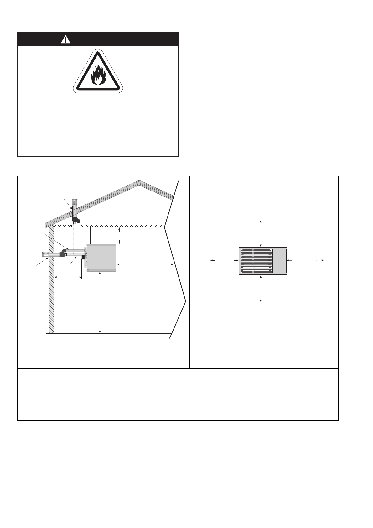
Figure 1: Installation Clearances and Clearances to Combustibles
Installation Clearances
Roof Terminal
Air
Intake
Wall
Terminal
Flue
60 cm
15 cm
3 m
2.5 - 3.5 m*
* Heaters may be mounted at a higher level if
destratification fans and/or turn down nozzles are
installed.
Clearances to Combustibles
15 cm
50 cm 50 cm**
30 cm
**80 cm is necessary to service heater.
The heater must always be installed at least 2.5 m above the floor.
The flue pipe must have clearance from combustibles by 5 cm.
If installed at low levels where individuals can come in contact with hot heat exchanger components,
adequate guarding must be provided.
All distances are minimum clearance requirements for service access, air flow and safety.
4

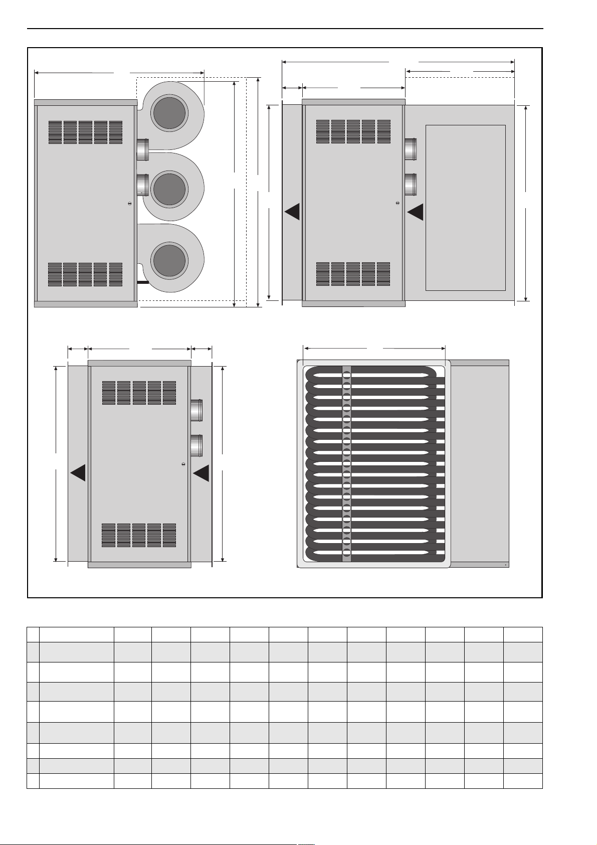
SECTION 4: SPECIFICATIONS
4.1 CTUA
SECTION 4: SPECIFICATIONS
Support
Centers
77
492
F
Top View
E
J
Rear View
Air Intake
Heater must be supported
at these points from above
or below.
C
G
D
4 x M10 Captive Nuts Provided
End View
Z
646
B
Gas
Supply
H
Lockout Reset
Flue
Electrical
Cable Entry
168
A
Dimension Data - CTUA (All Models)
Model 22 30 35 40 50 60 75 90 100 115
A
Width
B
Height
C
Support Spacing
D
Support Spacing
E
Support Spacing
F
Centre of Flue
G
Centre of Flue/Air Intake
H
Position of Flue
J
Gas Inlet Position
Z
Length
Flue/Air Intake Pipe Size
Weight kg 84 84 88 92 115 122 160 169 194 203
mm
(in)
mm
(in)
mm
(in)
mm
(in)
mm
(in)
mm
(in)
mm
(in)
mm
(in)
mm
(in)
mm
(in)
mm Ø
(in) Ø
1075
(42.3)
610
(24)
450
(17.7)
312
(12.3)
315
(12.4)
240
(9.5)
140
(5.5)
218
(8.6)
150
(5.9)
756
(29.8)
100
(3.9)
1075
(42.3)
610
(24)
450
(17.7)
312
(12.3)
315
(12.4)
240
(9.5)
140
(5.5)
218
(8.6)
150
(5.9)
756
(29.8)
100
(3.9)
1075
(42.3)
610
(24)
450
(17.7)
312
(12.3)
315
(12.4)
240
(9.5)
140
(5.5)
218
(8.6)
150
(5.9)
756
(29.8)
100
(3.9)
1075
(42.3)
610
(24)
450
(17.7)
312
(12.3)
315
(12.4)
240
(9.5)
140
(5.5)
218
(8.6)
150
(5.9)
756
(29.8)
100
(3.9)
1075
(42.3)
895
(35.2)
450
(17.7)
312
(12.3)
315
(12.4)
430
(16.9)
140
(5.5)
211
(8.3)
150
(5.9)
806
(31.8)
100
(3.9)
1075
(42.3)
895
(35.2)
450
(17.7)
312
(12.3)
315
(12.4)
430
(16.9)
140
(5.5)
211
(8.3)
150
(5.9)
806
(31.8)
100
(3.9)
1327
(52.3)
1100
(43.3)
627
(24.7)
312
(12.3)
388
(15.3)
346
(13.6)
225
(8.9)
260
(10.2)
220
(8.7)
756
(29.8)
130
(5.1)
1327
(52.3)
1100
(43.3)
627
(24.7)
312
(12.3)
388
(15.3)
346
(13.6)
225
(8.9)
260
(10.2)
220
(8.7)
756
(29.8)
130
(5.1)
(52.3)
(24.7)
(12.3)
(15.3)
(21.1)
(10.2)
(31.8)
1327
1345
(53)
627
312
388
537
225
(8.9)
260
220
(8.7)
806
130
(5.1)
1327
(52.3)
1345
(53)
627
(24.7)
312
(12.3)
388
(15.3)
537
(21.1)
225
(8.9)
260
(10.2)
220
(8.7)
806
(31.8)
130
(5.1)
5
COMBAT® CTU UNIT HEATERS INSTALLATION OPERATION AND SERVICE MANUAL
4.2 CTUB, CTUC and CTUD
K
End View
CTUB/C (All Models)
115 115
646
1440
115
646
ML
N
End View
CTUC (All Models)
P
679
N
N
End View
CTUD (All Models)
N
Front View
CTUD (And other models fitted with air outlet spigots)
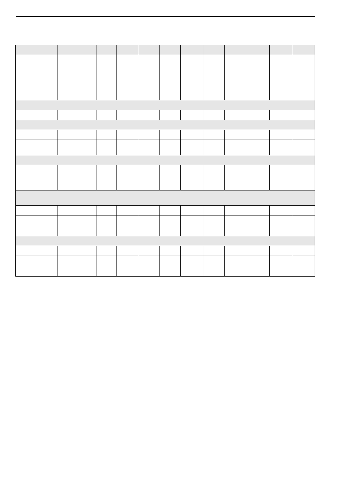
Dimension Data - CTUB, CTUC and CTUD
Model 22 30 35 40 50 60 75 90 100 115
K
CTUB Depth
L
CTUB Height
M
CTUC Height
Inlet & Outlet Duct
N
Spigot Height
Inlet & Outlet Duct
P
Spigot Width
Weight CTUB kg 96 96 100 104 139 146 185 210 228 237
Weight CTUC kg 109 109 113 117 157 163 206 215 251 260
Weight CTUD kg 93 93 97 101 124 131 172 181 200 209
mm
(in)
mm
(in)
mm
(in)
mm
(in)
mm
(in)
1026
(40.4)
610
(24)
610
(24)
534
(21)
709
(27.9)
1026
(40.4)
610
(24)
610
(24)
534
(21)
709
(27.9)
1026
(40.4)
610
(24)
610
(24)
534
(21)
709
(27.9)
1026
(40.4)
610
(24)
610
(24)
534
(21)
709
(27.9)
1026
(40.4)
895
(35.2)
895
(35.2)
817
(32)
707
(27.8)
1026
(40.4)
895
(35.2)
895
(35.2)
817
(32)
707
(27.8)
1076
(42.4)
1100
(43.3)
1100
(43.3)
1024
(40.3)
888
(35)
1076
(42.4)
1100
(43.3)
1100
(43.3)
1024
(40.3)
888
(35)
1076
(42.4)
1380
(54.3)
1431
(56.3)
1233
(48.5)
NOTE: Inlet and outlet duct spigot fitted with 30 mm flange.
888
(35)
1076
(42.4)
1380
(54.3)
1431
(56.3)
1233
(48.5)
888
(35)
6

SECTION 4: SPECIFICATIONS
4.3 General Technical Data Table
Model CTU-22 CTU-30 CTU-35 CTU-40 CTU-50 CTU-60 CTU-75 CTU-90 CTU-100 CTU-115
CTUA With Axial Fan
Total Electrical Load W 210 210 210 210 415 415 510 510 745 745
Run Current A 1. 0 1. 0 1. 0 1. 0 1. 7 2 1. 7 2 1. 9 1. 9 3.2 3.2
Start Current A 1. 4 1. 4 1. 4 1. 4 2.4 2.4 2.8 2.8 4.5 4.5
Air Flow m3/h 3800 4000 4000 4000 5500 5500 7500 7500 11,000 11 ,0 0 0
Sound Pressure Level
at 3 m
CTUB with Centrifugal Fan and CTUC Range with Centrifugal Fan and Duct Inlet
Total Electrical Load W 550 550 550 550 110 0 110 0 110 0 11 00 1650 1650
Normal Run Current A 4.6 4.6 4.6 4.6 11. 0 11.0 11.0 11. 0 15.6 15.6
Normal Start Current A 9.0 9.0 9.0 9.0 13.5 13.5 13.5 13.5 19.2 19.2
Normal Speed Medium Medium Medium Medium Medium Medium Medium Medium Medium Medium
High Run Current A 5.5 5.5 5.5 5.5 14.0 14.0 14.0 14.0 21.0 21.0
High Start Current A 13.6 13.6 13.6 13.6 17.2 17.2 17.2 17.2 25.8 25.8
Air Flow m3/h 3300 3300 3300 3300 5500 5500 6400 6400 9400 9400
Sound Pressure Level
at 3 m
[NR]
dB(A)
[NR]
dB(A)
[51]
56
[59]
59.5
[51]
56
[59]
59.5
[51]
56
[59]
59.5
[51]56[52.1]
[59]
59.5
57.1
[61]
61.5
[52.1]
57.1
[61]
61.5
[52.3]
57.3
[62]
61.8
[52.3]
57.3
[62]
61.8
[52.3]
57.3
[63]
64.2
[52.3]
57.3
[63]
64.2
CTUD Duct Heater with No Fan
**Minimun Air Flow
Required m3/h 3300 3300 3300 3300 5500 5500 6400 6400 9400 9400
Pressure Loss Across
Heat Exchanger Pa 30 30 30 30 30 30 30 30 30 30
Flue and AIr Intake
Flue and Air Intake
Size mm Ø 100 100 100 100 100 100 130 130 130 130
*Maximum Straight
Flue/Air Intake m 7 8 8 10 13 15 15 17 20 20
Electrical load at 230 V 50 Hz measured by calculating from total run current of appliance.
* Do not exceed the maximum length of flue stated or heater may not operate properly. Reduce the
maximum length stated by 1 m for each 90° bend installed.
**If minimum air flow requirements are not met, then temperature limit devices will shut down the heater.
7
COMBAT® CTU UNIT HEATERS INSTALLATION OPERATION AND SERVICE MANUAL
4.4 Technical Data Table
Appliance Category II
Heat Input
Gross CVkW(Btu/h) x (1000)2793
Heat Input
Net CV
(Btu/h) x (1000)2584
2H/L 3B/P
Model CTU-22 CTU-30 CTU-35 CTU-40 CTU-50 CTU-60 CTU-75 CTU-90 CTU-100 CTU-115
kW
33
113
30
102
39
133
35
119
48
163
43
147
61
210
55
189
70
238
63
215
95
324
86
292
111
378
100
341
119
405
107
365
134
459
121
414
Approximate
Heat OutputkW(Btu/h) x (1000)2378
Thermostat Limit Thermodisc
CTUA, B/C, D °C 75 75 75 75 75 75 75 75 75 75
Natural Gas (G20) Data - Inlet Pressure 20 mbar (7.8 in WG) Min. 17 mbar (6.8 in WG) Max. 25 mbar (10 in WG)
Burner Pressure mbar 8.3 8.7 8.5 9.4 9.3 8.5 6.1 6.0 6.2 6.3
Gas Rate
Natural Gas (G25) Data - Inlet Pressure 25 mbar (10 in WG) Min. 20 mbar (7.8 in WG) Max. 30 mbar (12 in WG)
Burner Pressure mbar 12.2 12.7 12.5 14.0 13.6 13.2 9.2 9.3 9.2 10.2
Gas Rate
LPG Gas Propane (G31) Data - Inlet Pressure 37 mbar (14.6 WG) Min. 25 mbar (10 in WG) Max. 45 mbar (18 in WG)
Alternative where permitted 50 mbar (20 in WG) Min. 42.5 bar (17 in WG) Max. 57.5 mbar (23 in WG)
Burner Pressure mbar 26.6 24.9 25.4 25.9 25.6 26.8 25.6 27.3 25.3 25.9
Gas Rate
LPG Gas Butane (G30) Data - Inlet Pressure 29 mbar (11,4 in WG) Min. 20 mbar (7.8 in WG) Max. 35 mbar (13.8 WG)
Burner Pressure mbar 18.9 17.4 17.8 19.5 18.4 19.0 18.3 19.4 18.3 18.7
m3/h
ft3/h
m3/h
ft3/h
m3/h
kg3/h
liquid/h
2.6
92
3.03
107
1. 0 1
1. 8 7
3.7
27
92
3.2
112
3.33
117
1. 2 3
2.28
4.5
32
109
3.7
131
4.31
152
1. 4 8
2.75
5.4
39
133
4.5
160
4.78
169
1. 7 7
3.27
6.4
51
174
5.8
206
6.14
217
2.27
4.21
8.3
58
198
6.6
234
6.98
247
2.58
4.79
9.4
78
266
9.0
319
9.49
335
3.51
6.50
12.8
91
310
10.5
371
11.0 6
391
4.09
7. 5 8
14.9
98
334
11.3
398
11.8 6
419
4.39
8.13
16.0
111
379
12.8
451
13.43
474
4.97
9.21
18.1
Gas Rate
m3/h
kg3/h
liquid/h
0.76
1. 8 6
3.2
0.93
2.27
4.0
1. 0 6
2.59
4.5
1. 3 4
3.26
5.7
1. 7 2
4.19
7. 3
Gas rates corrected to standard conditions 1013.25 mbar 15° C.
1. 9 5
4.77
8.3
2.65
6.47
11.3
3.09
7. 5 5
13.2
3.32
8.09
14.1
3.75
9.17
16.0
8

SECTION 5: HEATER INSTALLATION
10 mm
Steel
Drop Rod
Washer
Nut
Unistrut
Channel Nut
Cone Point
Set Pin
Window
Clamp
Unistrut
10 mm
Steel
Drop Rod
Nut
Washer
Riv
Nut
5.1 General
Heaters are designed for installation above 2.5 m.
These heaters must be installed within the heated
space. Duct delivery systems are not permitted with
axial fans.
5.2 Handling
All CTU heaters are supplied secured to a wooden
pallet and shrink wrapped. Use the pallet to support
the heater during handling and installation. When
handling or supporting the heater from below,
ensure that the weight is taken at the support points.
Figure 2: Suspension Methods
Insure all suspension hardware
is torqued to a minimum
of 27 Nm (20 ft lbs)
SECTION 5: HEATER INSTALLATION
5.3 Shelf Mounting and Suspension
WARNING
Crush Hazard
Use 10 mm steel drop rod
minimum.
Failure of the supports can
result in death, injury
or property damage.
For typical suspension See Page 9, Figure 2.
Support Points
9
COMBAT® CTU UNIT HEATERS INSTALLATION OPERATION AND SERVICE MANUAL
SECTION 6: FLUE INSTALLATION
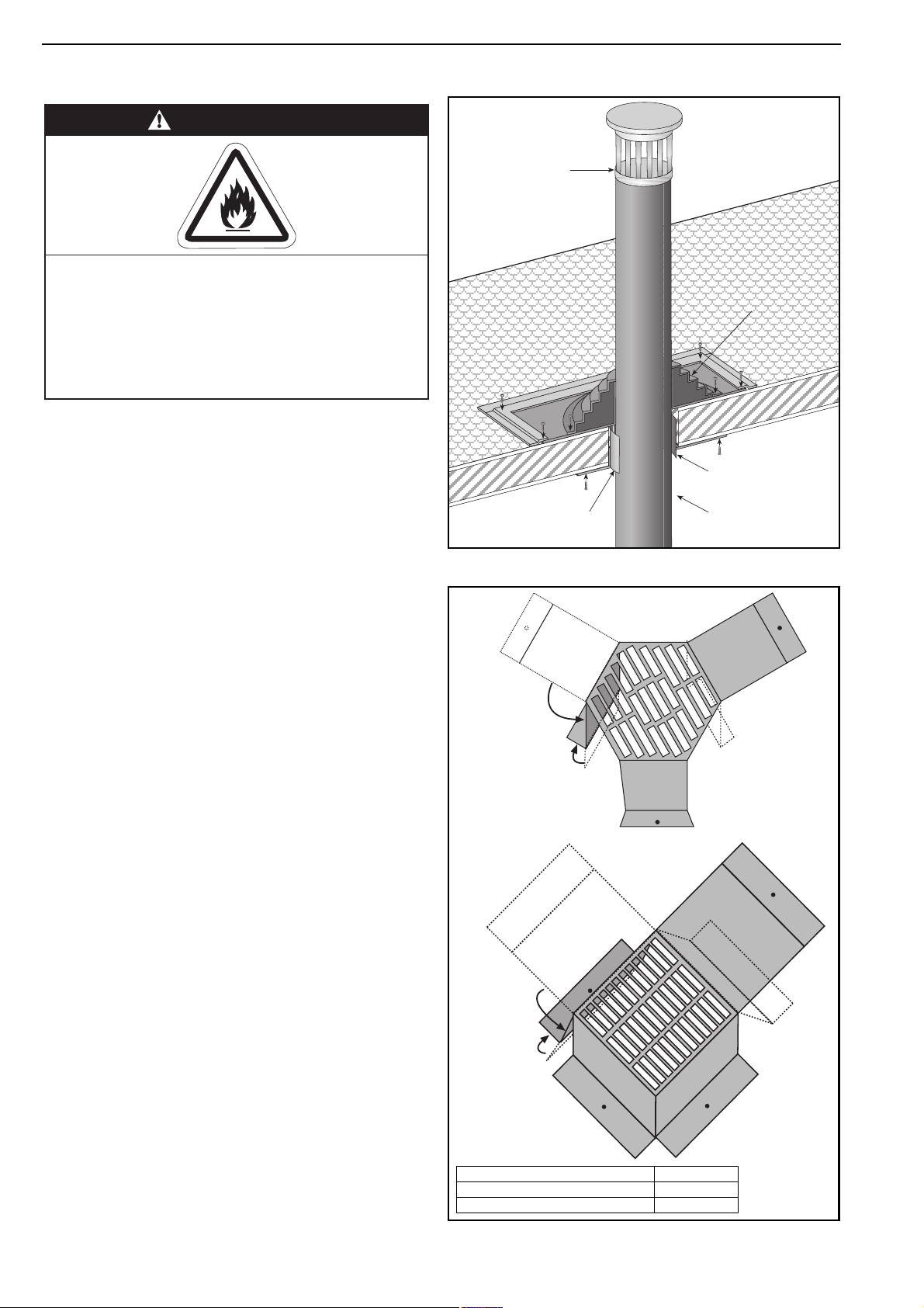
6.1 Flue Installation
Figure 3: Flue and Roof Detail
WARNING
Terminal
Flue
Fire Hazard
Some objects will catch fire or explode when placed
close to heater.
Keep all flammable objects, liquids and vapours the
required distance away from the heater.
Failure to follow these instructions can result in death,
injury or property damage.
The flue must terminate outside of the building.
Flues and air intakes must be a fully sealed system
and correctly sized for the model. Flues should be
assembled as detailed
on Page 10, Figure 3 through
Page 11, Figure 6. The joints between the flue
terminal and the roof or wall must be properly
sealed. If the flue passes through a wall or ceiling of
combustible material, it must be enclosed by a
sleeve of non-combustible material and be
separated from the sleeve by at least a 25 mm air
gap.
Flues and air intakes must be adequately
supported so that the heater does not bear the
weight of the pipes.
For flue termination See Page 10, Figure 3 through
Page 11, Figure 6.
6.2 Type C12, C32 & C62 Appliance
Room Sealed.
The heaters are designed to be installed as room
sealed appliances. The flue and air intake are run as
separate pipes to the special concentric wall or roof
terminal.
See Page 11, Figure 6.
Roof
25 mm Air Gap to
Combustible Material
Figure 4:
Air Intake Terminal Cover
Fold Leg
Down
Fold Foot
Out
Masterflash
Soaker Flashing
or Rain Collar.
Metal Sleeve
Flue
6.3 Type B22 Appliance
The flue must terminate outside the building and be
fitted with a low resistance terminal.
See Page 10, Figure 3 through Page 11, Figure 5.
6.3.1 Air Intake Terminal Cover
For Type B22 appliance installations, an air intake
terminal cover is an available option. The cover is
scored flat sheet metal that must be bent into shape.
See Page 10, Figure 4. Remove and retain the
screws for the air inlet spigot. Use these screws to
attach the cover in position over the spigot.
10
Fold Leg
Down
Fold Foot
Out
Description Part Number
Air Intake Terminal Cover (100mm) F078A
Air Intake Terminal Cover (130mm) F077A
 Loading...