


EP-200 Series
Pump
Installation,
Operation &
Service Manual
 WARNING
Improper installation, adjustment, alteration, service or maintenance can result in death, injury or property damage. Read the installation, operation and service manual thoroughly before installing or servicing this equipment.
Installation must be done by a contractor qualified in the installation and service of gas-fired heating equipment or your gas supplier.
Installer
Please take the time to read and understand these instructions prior to any installation.
Installer must give a copy of this manual to the owner.
Owner
Keep this manual in a safe place in order to provide your serviceman with necessary information.
|
Roberts-Gordon |
Roberts-Gordon |
|
1250 William Street |
76 Main Street West, Unit 10 |
|
P.O. Box 44 |
Grimsby, Ontario, L3M 1R6 |
|
Buffalo, New York 14240-0044 |
Canada |
|
Telephone: 716.852.4400 |
Telephone: 905.945.5403 |
|
Fax: 716.852.0854 |
Fax: 905.945.0511 |
|
Toll Free: 800.828.7450 |
|
Quality in Any Language™ |
www.rg-inc.com |
|
© Copyright 2004 Roberts-Gordon |
P/N 127200NA Rev. F 12/04 |

TABLE OF CONTENTS |
|
|
SECTION 1: Heating System Safety ............................ |
1 |
|
1.1 |
Manpower Requirements ................................... |
1 |
SECTION 2: Installer Responsibility............................ |
2 |
|
2.1 |
Corrosive Chemicals........................................... |
2 |
2.2 |
National Standards and Applicable Codes ......... |
2 |
SECTION 3: Unpacking the Pump ............................... |
2 |
|
3.1 |
Open Shipping Cartons ...................................... |
2 |
SECTION 4: Major Components .................................. |
3 |
|
4.1 |
Standard Parts List ............................................. |
4 |
SECTION 5: Pump Installation ..................................... |
6 |
|
5.1 |
Pump Assembly Instructions .............................. |
6 |
5.2 |
Pump Suspension .............................................. |
9 |
5.3 |
Condensate Trap and Condensate Tee ............ |
11 |
SECTION 6: Motor Wiring........................................... |
12 |
|
6.1 |
Prior to Operation ............................................. |
12 |
SECTION 7: Venting.................................................... |
13 |
|
7.1 |
General Venting Requirements......................... |
13 |
7.2 |
Venting the Pump ............................................. |
13 |
7.3 |
Horizontal Venting ............................................ |
13 |
7.4 |
Vertical Venting................................................. |
15 |
SECTION 8: Servicing Instructions ........................... |
16 |
|
8.1 |
Pre-Season Maintenance and |
|
|
Annual Inspection ............................................. |
16 |
8.2 |
To Change the Motor and/or the Impeller ......... |
16 |
8.3 |
Maintenance Checklist ..................................... |
17 |
SECTION 9: Replacement Parts and Accessories ... |
18 |
|
9.1 |
Replacement Parts ........................................... |
18 |
9.2 |
Accessories ...................................................... |
18 |
SECTION 10: Specifications....................................... |
19 |
|
SECTION 11: The ROBERTS GORDON® EP-200 |
|
|
|
SERIES PUMP Limited Warranty ....... |
21 |
© 2004 


All rights reserved. No part of this work covered by the copyrights herein may be reproduced or copied in any form or by any means - graphic, electronic, or mechanical, including photocopying, recording, taping or information storage and retrieval systems - without the written permission of Roberts-Gordon.
Printed in U.S.A.

TABLE OF FIGURES |
|
Figure 1: Major Component Descriptions ....................... |
3 |
Figure 2: Pump Discharge Orientation / |
|
Impeller Rotation Direction .............................. |
6 |
Figure 3: Pump Assembly ............................................... |
7 |
Figure 4: Motor Shaft Seal Assembly.............................. |
8 |
Figure 5: Wall Bracket Assembly .................................... |
9 |
Figure 6: Wall Mounting Angle Assembly........................ |
9 |
Figure 7: Wall Mounting ................................................ |
10 |
Figure 8: Mounting Platform Assembly ......................... |
10 |
Figure 9: Condensate Check Valve............................... |
11 |
Figure 10: Condensate Tee - Discharge Side ............... |
11 |
Figure 11: EP-201 Motor Wiring ................................... |
12 |
Figure 12: EP-203 Motor Wiring ................................... |
12 |
Figure 13: Side Wall Venting ......................................... |
14 |
Figure 14: Vertical Venting ............................................ |
15 |

SECTION 1: HEATING SYSTEM SAFETY
SECTION 1: HEATING SYSTEM SAFETY
Your Safety is Important to Us! This symbol is used throughout the manual to notify you of possible fire, electrical or burn hazards. Please pay special attention when reading and following the warnings in these sections.
Installation, Service and Annual Inspection of heater and pump must be done by a contractor qualified in the installation and service of gas-fired heating equipment.
Read this manual carefully before installation, operation or service of this equipment.
This heating system is designed for heating nonresidential indoor spaces. Do not install in residential spaces. These instructions, the layout drawing, local codes and ordinances, and applicable standards that apply to electrical wiring, venting, etc., must be thoroughly understood before proceeding with the installation.
Thin sheet metal parts, such as the various venting components, have sharp edges. To prevent injury, the use of work gloves is recommended.
Do not attempt to operate the pump until all steps of the installation have been accomplished.
1.1 Manpower Requirements
To prevent personal injury and damage to the pump, two persons will be required for installation.
1
EP-200 SERIES PUMP INSTALLATION, OPERATION AND SERVICE MANUAL
SECTION 2: INSTALLER RESPONSIBILITY
The installer is responsible for the following:
•To install the pump and electrical supplies, in accordance with applicable specifications and codes. Roberts-Gordon recommends the installer contact a local building inspector or Fire Marshal for guidance.
•To use the information given in a layout drawing and in the manual together with the cited codes and regulations to perform the installation.
•To furnish all needed materials not furnished as standard equipment.
•To plan location of supports.
•To provide access to pump for servicing on all sides and for pump removal.
•To provide the owner with a copy of this installation, operation and service manual.
•To never use pump or pump platform as support for ladder or other access equipment and never hang or suspend anything from pump or pump platform.
•To safely and adequately install pump using materials with a minimal working load of 400 lb (181 kg).
2.1 Corrosive Chemicals
 CAUTION
Do not use heater and pump in an area containing corrosive chemicals.
Avoid the use of corrosive chemicals to ensure a longer life of the pump, burner, tubing and other parts.
Failure to follow these instructions can result in property damage.
Roberts-Gordon cannot be responsible for ensuring that all appropriate safety measures are undertaken prior to installation; this is entirely the responsibility of the installer. It is essential that the contractor, the sub-contractor, or the owner identifies the presence of combustible materials, corrosive chemicals or halogenated hydrocarbons* anywhere in the premises.
* Halogenated Hydrocarbons are a family of chemical compounds characterized by the presence of halogen elements (fluorine, chlorine, bromine, etc.). These compounds are frequently used in refrigerants, cleaning agents, solvents, etc. If these compounds enter the air supply of the burner, the life span of the heater components will be greatly reduced. An outside air supply must be provided to the burners whenever the presence
of these compounds is suspected. Warranty will be invalid if the heater is exposed to halogenated hydrocarbons.
2.2 National Standards and Applicable Codes
All Appliances must be installed in accordance with the latest revision of the applicable standards and national codes. This refers also to the electric, gas and venting installation. Note: Additional standards for installations in Public Garages, Aircraft Hangars, etc. may be applicable.
SECTION 3: UNPACKING THE PUMP
3.1 Open Shipping Cartons
Open cartons and remove packing inserts. Carefully remove pump components from the cartons. Lift assembly by gripping metal pump frame. Two people are required (weight 112 lb, 51 kg). This pump has been tested prior to packing. The impeller was dynamically balanced before assembly and requires care in handling to avoid damage.
 WARNING
Severe Injury Hazard
Install pump scroll and inlet assembly before operating high speed rotating impeller.
Keep hands, fingers and clothing away from inlet and outlet.
Install and operate equipment according to installation manual.
Failure to follow these instructions can result in death or severe injury.
2
SECTION 4: MAJOR COMPONENTS
SECTION 4: MAJOR COMPONENTS
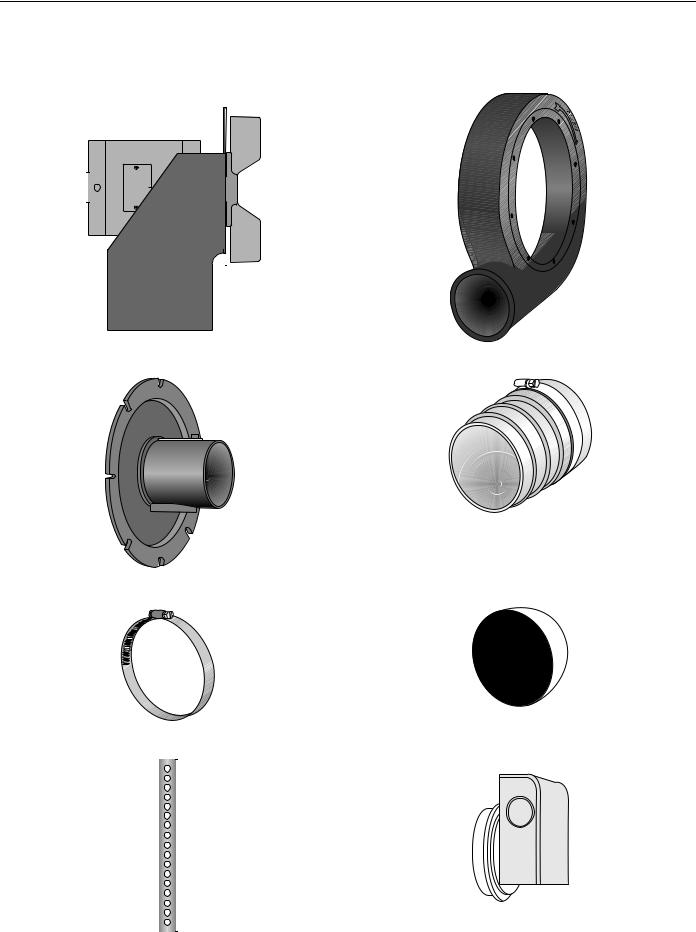
FIGURE 1: Major Component Descriptions
EP-201 Pump Assembly - 01312001 |
Pump Scroll Assembly - 01394400 |
|||||||
EP-203 Pump Assembly - 01312002 |
|
|
|
|||||
|
|
|
|
|
|
|
|
|
|
|
|
|
|
|
|
|
|
|
|
|
|
|
|
|
|
|
|
|
|
|
|
|
|
|
|
|
|
|
|
|
|
|
|
|
|
|
|
|
|
|
|
|
|
|
|
|
|
|
|
|
|
|
|
|
|
|
|
|
|
|
|
|
|
|
|
|
|
|
|
|
|
|
|
|
|
|
|
|
|
Inlet Plate Assembly - 01327400 |
Pump Boot 4" (10 cm) - 91412800 |
Band Clamp 4" (10 cm) - 91901300 |
Bird Screen 4" (10 cm) - 01365400 |
||
|
|
|
|
|
|
|
|
Mounting Angle - 01365000 |
Pressure Switch - 90430600 |
||||||||
|
|
|
|
|
|
|
|
|
|
|
|
|
|
|
|
|
|
|
|
|
|
|
|
|
|
|
|
|
|
|
|
|
|
|
|
|
|
|
|
|
|
|
|
|
|
|
|
|
|
|
|
|
|
|
|
|
|
|
|
|
|
|
|
|
|
|
|
|
|
|
|
|
|
|
|
|
|
|
|
|
|
|
|
|
|
|
|
|
|
|
|
|
|
|
|
|
|
|
|
|
|
|
|
|
|
|
|
|
|
|
|
|
|
|
|
|
|
|
|
|
|
|
|
|
|
|
|
|
|
|
|
|
|
|
|
|
|
|
|
|
|
|
|
|
|
|
|
|
|
3
 Loading...