


FOR YOUR SAFETY
If you smell gas:
1.Open windows.
2.DO NOT try to light any appliance.
3.DO NOT use electrical switches.
4.DO NOT use any telephone in your building.
5.Leave the building.
6.Immediately call your local gas supplier after leaving the building. Follow the gas supplier’s instructions.
7.If you cannot reach your gas supplier, call the Fire Department.
DO NOT store or use petrol or other flammable vapors and liquids in the vicinity of this or any other appliance.
Blackheat®
Vacuum Assisted
Linear & U-Tube
Gas Fired Radiant
Heating
Systems
Installation, Operation &
Service Manual
BH15
BH20
BH25
BH30
BH35
BH40
BH45
BH50
 WARNING
Improper installation, adjustment, alteration, service or maintenance can result in death, injury or property damage. Read the installation, operation and service manual thoroughly before installing or servicing this equipment.
Installation must be done by a contractor qualified in the installation and service of gas-fired heating equipment.
Installer
Please take the time to read and understand these instructions prior to any installation.
Installer must give a copy of this manual to the owner.
Owner
Keep this manual in a safe place to provide your serviceman with information should it become necessary.
Hurll Nu-Way Pty Ltd
14 Aristoc Road
GLEN WAVERLEY VIC 3150
Telephone: +61 3 9561 2100
Fax: +61 3 9560 8992
www.rg-inc.com
170101AUNZ |
Rev. 2 |
4/03 |

TABLE OF CONTENTS |
Note: Pages 2,16,17,18,23,32,35,46,54,55 have been deleted as not relevant. |
|||||
SECTION 1: Heater Safety...................................................... |
|
1 |
SECTION 12: Venting ............................................................ |
42 |
||
SECTION 2: Installer Responsibility |
..................................... |
1 |
12.1 |
Flue Installation........................................................ |
42 |
|
2.1 |
Low Level User Instructions......................................... |
|
1 |
12.2 |
Flueless Installation (U.K. Only)............................... |
42 |
2.2 |
Halogenated Hydrocarbons ......................................... |
|
1 |
12.3 |
Ventilation Requirements ......................................... |
42 |
2.3 |
National Standards and Applicable Codes .................. |
1 |
12.4 |
Outside Combustion Air Supply ............................... |
43 |
|
SECTION 3: Critical Considerations |
..................................... |
3 |
12.5 Common Duct .......................................................... |
43 |
||
3.1 |
Minimum Required Clearances to Combustibles......... |
3 |
SECTION 13: Gas Piping ...................................................... |
44 |
||
3.2 |
Clearance Data - Linear................ |
4 |
|
SECTION 14: Wiring.............................................................. |
45 |
|
3.3 |
Clearance Data -U Tube................. |
6 |
|
14.1 |
BLACKHEAT® Typical External Wiring Diagram |
|
SECTION 4: Specifications .................................................... |
|
8 |
(Linear or U Tube) ............................................................ |
45 |
||
4.1 |
Material Specifications................................................. |
|
8 |
|
|
|
4.2 |
Heater Specifications................................................... |
|
8 |
|
|
|
4.3 |
Venting Specifications.................................................. |
|
8 |
|
|
|
4.4 |
Suspension Specifications........................................... |
|
8 |
|
|
|
4.5 |
Controls Specifications ................................................ |
|
8 |
|
|
|
4.6 |
Linear Heater............................................................... |
|
9 |
|
|
|
|
|
|
|
14.5 |
BLACKHEAT® Internal Wiring Diagram ................. |
47 |
4.8 |
U-Tube Heater ............................................................. |
|
9 |
SECTION 15: Operation ........................................................ |
48 |
|
4.9 |
Burner Specifications................................................. |
|
10 |
15.1 |
Heater Lockout Indication (Optional)........................ |
48 |
SECTION 5: Major Component Descriptions ..................... |
11 |
15.2 |
Testing...................................................................... |
48 |
||
SECTION 6: General Suspension Details .......................... |
12 |
15.3 |
Commisioning .......................................................... |
48 |
||
6.1 |
Suspension Details .................................................... |
|
12 |
15.4 |
System Checks ........................................................ |
49 |
SECTION 7: Linear Heater Installation........................... ... |
13 |
15.5 |
User Instructions ...................................................... |
49 |
||
7.1 |
Linear Standard Parts List ......................................... |
|
13 |
SECTION 16: Servicing Instructions ................................... |
50 |
|
|
|
|
|
16.1 |
Annual Procedure .................................................... |
50 |
7.3 |
Burner Tube Installation ............................................ |
|
19 |
16.2 |
Component Removal ............................................... |
50 |
7.4 |
Coupling and Tube Assembly.................................... |
|
19 |
SECTION 17: Troubleshooting ............................................. |
52 |
|
7.5 |
Tube Clamp Package Installation .............................. |
21 |
17.1 Troubleshooting Flow Chart (Linear and |
|
||
7.6 |
Reflector Installation .................................................. |
|
21 |
U-Tube) ............................................................................ |
52 |
|
|
|
|
|
17.3 |
Manifold Gas Pressure Setting ................................ |
56 |
SECTION 8: U-Tube Heater Installation .............................. |
24 |
SECTION 18: Replacement Parts......................................... |
57 |
|||
8.1 |
U-Tube Standard Parts List........................................ |
|
24 |
|
|
|
8.2 |
Critical Hanger Placement......................................... |
|
27 |
|
|
|
8.3 |
Burner Tube and Fan Tube Installation .................... |
27 |
|
|
|
|
8.4 |
U-Tube Support Bracket Assembly Installation ......... |
28 |
|
|
|
|
8.5 |
Coupling and Tube Assembly.................................... |
|
29 |
|
|
|
8.6 |
Tube Installation ........................................................ |
|
30 |
|
|
|
8.7 |
U-Tube Installation .................................................... |
|
30 |
|
|
|
8.8 |
Reflector Installation .................................................. |
|
31 |
|
|
|
SECTION 10: Burner & Fan Installation .............................. |
33 |
|
|
|
||
10.1 Burner Installation.................................................... |
|
33 |
|
|
|
|
10.2 Fan Assembly.......................................................... |
|
33 |
|
|
|
|
10.3 Linear & U-Tube Fan Installation.............................. |
34 |
|
|
|
||
SECTION 11: Optional Heater Accessories........................ |
36 |
|
|
|
||
11.1 Reflector Side Extension Installation ....................... |
36 |
|
|
|
||
11.2 Decorative Grille Installation .................................... |
|
37 |
|
|
|
|
11.3 Protective Grille Installation ..................................... |
|
38 |
|
|
|
|
11.4 Sports Hall Guard Installation.................................. |
39 |
|
|
|
||
11.5 Universal Shield Installation..................................... |
|
40 |
|
|
|
|
11.6 Undershield Installation ........................................... |
|
41 |
|
|
|
|
© 2001 


All rights reserved. No part of this work covered by the copyrights herein may be reproduced or copied in any form or by any means - graphic, electronic, or mechanical, including photocopying, recording, taping or information storage and retrieval systems - without the written permission of Roberts-Gordon.
TABLE OF FIGURES
Figure 1: Deleted |
|
|
Figure 2: Linear Horizontal Mounts ............... |
4 |
|
Figure 3: Linear, One Side Reflector.............. |
4 |
|
Figure 4: Linear, Two Side Reflectors ............ |
4 |
|
Figure 5: Linear, 45° Mount............................ |
4 |
|
Figure 6: Linear, 1 Foot and 2 Foot Deco |
|
|
Grille .......................................................................... |
|
5 |
Figure 7: Linear, Protective Grille................... |
5 |
|
Figure 8: Linear, Venting ................................ |
5 |
|
Figure 9: U-Tube, Horizontal Mount .......................................... |
|
6 |
Figure 10: U-Tube, One Side Reflector ..................................... |
|
6 |
Figure 11: U-Tube, Two Side Reflectors ................................... |
|
6 |
Figure 12: U-Tube, Full 45° Mount ............................................ |
|
6 |
Figure 13: U-Tube, Opposite 45° Tilt......................................... |
|
7 |
Figure 14: U-Tube, Protective Grille .......................................... |
|
7 |
Figure 15: U-Tube, Venting ....................................................... |
|
7 |
Figure 16: BLACKHEAT® Linear and U-Tube |
........................ |
10 |
Figure 17: BLACKHEAT® Linear General Assembly |
|
|
Overview................................................................ |
|
14 |
Figure 18: BLACKHEAT® Linear Layout Overviews .............. |
15 |
|
Figure 19: Deleted |
|
|
Figure 20: Deleted |
|
|
Figure 21: Reflector Overlap Detail......................................... |
|
22 |
Figure 22: BLACKHEAT® BH15UT Assembly Overview ....... |
25 |
|
Figure 23: BLACKHEAT® U-Tube Layout Overviews............. |
26 |
|
Figure 24: Deleted |
|
|
Figure 25: Typical Manifold Layout (Linear and U-Tube |
|
|
Configuration) ........................................................ |
|
32 |
Figure 26: Individual Flue Connection Detail .......................... |
|
42 |
Figure 27: Fresh Air Intake Spigot .......................................... |
|
43 |
Figure 28: Air Supply with Flue Configurations....................... |
43 |
|
Figure 29: Gas Connection with Stainless Steel Flex |
|
|
Connector .............................................................. |
|
44 |
Figure 30: Sequence of Operation Chart................................ |
|
48 |
Figure 31: Burner Cup Position............................................... |
|
50 |

SECTION 1: HEATER SAFETY
SECTION 1: HEATER SAFETY
Your Safety is Important to Us!
This symbol is used throughout the manual to notify you of possible fire, electrical or burn hazards. Please pay special attention when reading and following the warnings in these sections.
 WARNING
Installation, Service and Annual Inspection of heater must be done by a contractor qualified in the installation and service of gas-fired heating equipment.
Read this manual carefully before installation, operation, or service of this equipment.
Failure to follow these instructions can result in death, injury or property damage.
A wall tag is supplied with the BLACKHEAT® heater as a permanent reminder of the safety instructions and the importance of the minimum required clearances to combustibles. A copy of the wall tag is illustrated on Page 2, Figure 1. Peel off the backing of the adhesive strips on the rear surface of the tag and position the tag on a wall near the BLACKHEAT® heater (e.g. thermostat or ROBERTS GORDON® BZC Microprocessor Controller).
2.2 Halogenated Hydrocarbons
 CAUTION
Do not use heater in an area containing corrosive chemicals.
Avoid the use of corrosive chemicals to ensure a longer life of the burner, tubing and other parts.
Failure to follow these instructions can result in property damage.
This heater is designed for heating non-residential indoor
spaces. Do not install in residential spaces. These instructions, layouts , AS5601/AG 601,local codes and
ordinances, and applicable standards that apply to gas piping, electrical wiring, venting, etc., must be thoroughly understood before proceeding with the installation.
SECTION 2: INSTALLER RESPONSIBILITY
•To install the heater, as well as the gas and electrical supplies, in accordance with applicable specifications and codes. Roberts-Gordon recommends the installer contact a local building inspector or Fire Marshal for guidance.
•To use the information given in a layout drawing and in the manual together with the cited codes and regulations to perform the installation.
•To install the heater in accordance with the Clearances to Combustibles.
•To furnish all needed materials not furnished as standard equipment.
•To plan location of supports.
•To provide access to burners for servicing on all sides, for burner removal.
•To provide the owner with a copy of this installation, operation and service manual.
•To never use heater as support for ladder or other access equipment and never hang or suspend anything from heater.
2.1 Low Level User Instructions
In all situations, clearances to combustibles must be maintained. Failure to observe clearances to combustibles can result in death, severe injury or property damage. Signs should be posted in storage areas to specify the maximum stacking height of items placed below heater to maintain required clearances to combustibles. Minimum clearances must be maintained from vehicles parked below the heater. Caution should be used when running the system near combustible materials such as wood, paper, rubber, etc. Consideration should be given to partitions, storage racks, hoists, building construction,etc.
Roberts-Gordon cannot be responsible for ensuring that all appropriate safety measures are undertaken prior to installation; this is entirely the responsibility of the installer. It is essential that the contractor, the subcontractor, or the owner identifies the presence of combustible materials or halogenated hydrocarbons* anywhere in the premises.
* Halogenated Hydrocarbons are a family of chemical compounds characterized by the presence of halogen elements (flourine, chlorine, bromine, etc.). These compounds are frequently used in refrigerants, cleaning agents, solvents, etc. If these compounds enter the air supply of the burner, the lifespan of the heater components will be greatly reduced. An outside air supply must be provided to the burners whenever the presence of these compounds is suspected. Warranty will be invalid if the heater is exposed to halogenated hydrocarbons.
2.3 National Standards and Applicable Codes
All Appliances must be installed in accordance with the latest revision of AS5601/AG 601 and other relevant
codes. This refers also to the electric, gas and venting installation. Note: Additional standards for installations in Public Garages, Aircraft Hangars, etc. may be applicable.
1
SECTION 3: CRITICAL CONSIDERATIONS
SECTION 3: CRITICAL CONSIDERATIONS
 WARNING
|
|
|
|
|
|
|
|
|
|
|
|
|
|
|
|
|
|
|
|
|
|
|
|
|
|
|
|
Fire Hazard |
|
|
Burn Hazard |
|||
Some objects will catch fire |
Keep all persons, |
|||||
or explode when placed |
especially children, away |
|||||
close to heater. |
from heater. |
|||||
Keep all flammable objects, |
Do not touch any part of |
|||||
liquids and vapors the |
the heater. |
|||||
minimum required |
Heater is very hot. |
|||||
clearances to combustibles |
||||||
away from heater. |
Failure to follow these |
|||||
Failure to follow these |
instructions can result in |
|||||
severe injury. |
||||||
instructions can result in |
||||||
death or injury. |
|
|
|
|
|
|
3.1 Minimum Required Clearances to Combustibles
Clearances are the required distances that combustible objects must be kept away from the heater to prevent serious fire hazards. Combustibles are materials, which may catch on fire and include common items such as wood, paper, rubber, fabric, etc. Maintain clearances to combustibles at all times for your safety.
Clearances for all heater models are located on Page 4, Figure 2 through Page 7, Figure 15 in this manual. Check the clearances on each burner for the model heater being installed to make sure the product is suitable for your application and the clearances are maintained. Read and follow the safety guidelines below:
•Keep petrol or other combustible materials including flammable objects, liquids, dust or vapours away from this heater or any other appliance.
•Maintain clearances from heat sensitive material, equipment and workstations.
•Maintain clearances from vehicles parked below the heater.
•Maintain clearances from swinging doors, overhead cranes, vehicle lifts, partitions, storage racks, hoists, etc.
•In locations used for the storage of combustible materials, signs must be posted to specify the maximum permissible stacking height to maintain required clearances from the heater to the combustibles. Signs must be posted adjacent to the heater thermostat. In the absence of a thermostat, signs must be posted in a conspicuous location.
•Consult local Building Inspector, Fire Insurance Carrier or other authorities for approval of proposed installation when there is a possibility of exposure to combustible airborne materials or vapours.
•Hang heater in accordance to the minimum suspension requirements on Page 9, Section 4.6 through Page 9, Section 4.8.
•If the radiant tubes must pass through the building structure, be sure that adequate sleeving and fire stop is installed to prevent scorching and/or fire hazard.
3
BLACKHEAT® INSTALLATION OPERATION AND SERVICE MANUAL
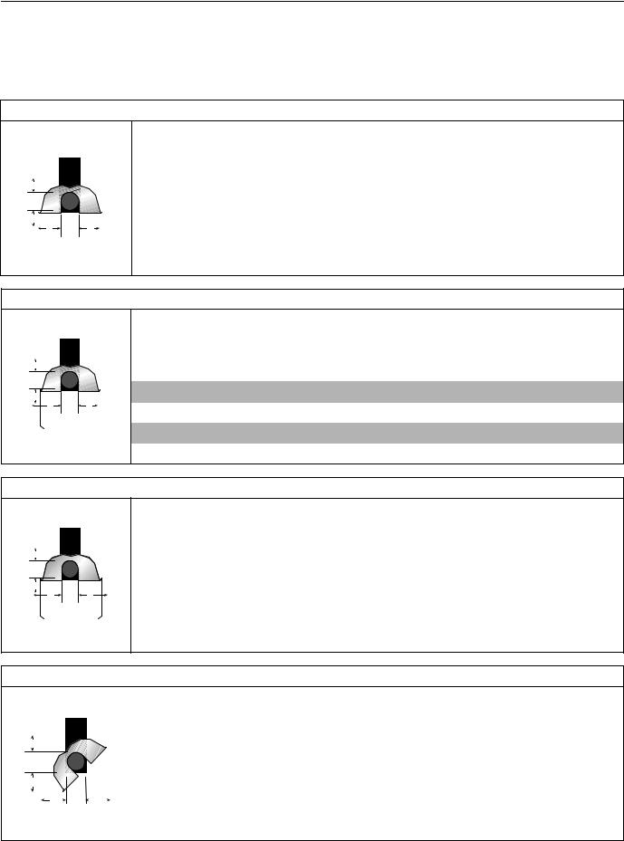
3.2 Clearance Data -
NOTE: 1. All dimensions are from the Tube surface.
2.Clearances B, C and D can be reduced by 50% after 7 m of tubing downstream from the burner.
3.All measurements are in Millimeters.
FIGURE 2: LINEAR , HORIZONTAL MOUNTS
A
C |
B |
D |
Model |
BH15 |
BH20 |
BH25 |
BH30 |
BH35 |
BH40 |
BH45 |
BH50 |
|
|
|
|
|
|
|
|
|
A |
150 |
150 |
150 |
150 |
150 |
150 |
200 |
200 |
B |
890 |
970 |
970 |
1020 |
1170 |
1220 |
1280 |
1330 |
|
|
|
|
|
|
|
|
|
C |
1570 |
1650 |
1650 |
1780 |
1930 |
1970 |
2010 |
2080 |
D |
890 |
970 |
970 |
1020 |
1170 |
1220 |
1280 |
1330 |
|
|
|
|
|
|
|
|
|
FIGURE 3: LINEAR , ONE SIDE REFLECTOR
A
C |
B |
D |
Model |
BH15 |
BH20 |
BH25 |
BH30 |
BH35 |
BH40 |
BH45 |
BH50 |
A |
150 |
150 |
150 |
150 |
150 |
150 |
200 |
200 |
B |
230 |
230 |
230 |
230 |
230 |
230 |
230 |
230 |
C |
1580 |
1760 |
1760 |
1930 |
2090 |
2130 |
2160 |
2240 |
D |
1200 |
1380 |
1380 |
1500 |
1660 |
1710 |
1760 |
1860 |
|
|
|
|
|
|
|
|
|
FIGURE 4: LINEAR, TWO SIDE REFLECTORS
A
C |
B |
D |
Model |
BH15 |
BH20 |
BH25 |
BH30 |
BH35 |
BH40 |
BH45 |
BH50 |
|
|
|
|
|
|
|
|
|
A |
150 |
150 |
150 |
150 |
150 |
150 |
200 |
200 |
B |
590 |
640 |
640 |
690 |
820 |
860 |
890 |
1020 |
|
|
|
|
|
|
|
|
|
C |
1660 |
1810 |
1810 |
1960 |
2110 |
2160 |
2210 |
2320 |
D |
590 |
640 |
640 |
690 |
820 |
860 |
890 |
1020 |
|
|
|
|
|
|
|
|
|
FIGURE 5: LINEAR, 45° MOUNT
A
C |
|
|
|
|
|
|
|
Model |
BH15 |
BH20 |
BH25 |
BH30 |
BH35 |
BH40 |
BH45 |
BH50 |
|
|
|
|
|
|
|
|
|
|
|
|
|
|
|
|
|
|
|
|
|
|
|
|
|
A |
200 |
200 |
200 |
250 |
250 |
275 |
300 |
300 |
|
B |
|
|
|
D |
|
|
B |
200 |
200 |
200 |
200 |
200 |
200 |
200 |
200 |
|
|
|
|
|
|
|
|
|
|
|
|
|
|
|
|||
C |
1500 |
1660 |
1660 |
1860 |
1960 |
2030 |
2110 |
2160 |
||||||||
|
|
|
||||||||||||||
|
|
|
|
|
|
|
||||||||||
|
|
|
|
|
|
|
D |
1370 |
1520 |
1520 |
1630 |
1750 |
1820 |
1880 |
2000 |
|
|
|
|
|
|
|
|
|
|
|
|
|
|
|
|
|
4
SECTION 3: CRITICAL CONSIDERATIONS
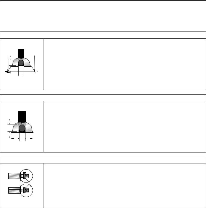
NOTE: 1. All dimensions are from the Tube surface.
2.Clearances B, C and D can be reduced by 50% after 7 m of tubing downstream from the burner.
3.All measurements are in Millimeters.
FIGURE 6: LINEAR , 1 FOOT AND 2 FOOT DECO GRILLE
A
C

 B
B 


 D
D

|
|
|
|
Model |
BH15 |
BH20 |
BH25 |
BH30 |
BH35 |
BH40 |
BH45 |
BH50 |
|
|
|
|
|
|
|
|
|
|
|
|
|
|
|
|
|
A |
150 |
150 |
150 |
150 |
150 |
150 |
200 |
200 |
|
|
|
|
B |
890 |
970 |
970 |
1020 |
1170 |
1220 |
1280 |
1330 |
|
|
|
|
|||||||||
|
|
|
|
|
|
|
|
|
|
|
|
|
|
|
|
|
C |
1570 |
1650 |
1650 |
1780 |
1930 |
1970 |
2010 |
2080 |
|
|
|
|
D |
890 |
970 |
970 |
1020 |
1170 |
1220 |
1280 |
1330 |
|
|
|
|
|
|
|
|
|
|
|
|
|
FIGURE 7: LINEAR , PROTECTIVE GRILLE
A
C 
B |
|
|
|
D |
Model |
BH15 |
BH20 |
BH25 |
BH30 |
BH35 |
BH40 |
BH45 |
BH50 |
|
|
|
|
|
|
|
|
|
A |
150 |
150 |
150 |
150 |
150 |
150 |
200 |
200 |
B |
890 |
970 |
970 |
1020 |
1170 |
1220 |
1280 |
1330 |
|
|
|
|
|
|
|
|
|
C |
1570 |
1650 |
1650 |
1780 |
1930 |
1970 |
2010 |
2080 |
D |
890 |
970 |
970 |
1020 |
1170 |
1220 |
1280 |
1330 |
|
|
|
|
|
|
|
|
|
FIGURE 8: LINEAR , VENTING
E
Unvented |
Radiant tubes |
Fan |
F |
Vented |
Model |
BH15 |
BH20 |
BH25 |
BH30 |
BH35 |
BH40 |
BH45 |
BH50 |
|
|
|
|
|
|
|
|
|
E |
1000 |
1000 |
1000 |
1000 |
1000 |
1000 |
1000 |
1000 |
F |
500 |
500 |
500 |
500 |
500 |
500 |
500 |
500 |
|
|
|
|
|
|
|
|
|
|
|
|
|
|
|
|
|
|
5
BLACKHEAT® INSTALLATION OPERATION AND SERVICE MANUAL
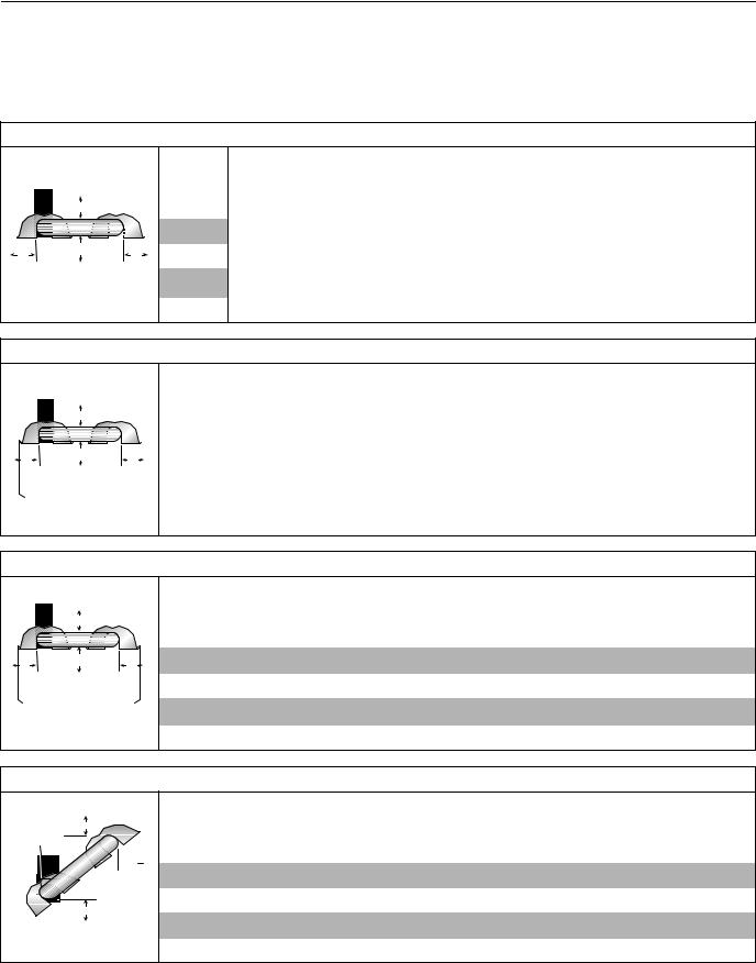
3.3 Clearance Data -U Tube
NOTE: 1. All dimensions are from the Tube surface.
2.Clearances B, C and D can be reduced by 50% after 7 m of tubing downstream from the burner.
3.All measurements are in Millimeters.
.
FIGURE 9: U-TUBE, HORIZONTAL MOUNT
A |
Model |
|
|
|
A |
B |
C |
D |
B |
|
C
D
BH15 |
BH20 |
BH25 |
BH30 |
BH35 |
BH40 |
BH45 |
BH50 |
|
|
|
|
|
|
|
|
150 |
150 |
150 |
150 |
150 |
150 |
200 |
200 |
890 |
970 |
970 |
1020 |
1170 |
1220 |
1270 |
1380 |
|
|
|
|
|
|
|
|
1580 |
1730 |
1730 |
1910 |
1980 |
2050 |
2110 |
2210 |
|
|
|
|
|
|
|
|
760 |
940 |
940 |
1000 |
1090 |
1150 |
1200 |
1300 |
|
|
|
|
|
|
|
|
FIGURE 10: U-TUBE, ONE SIDE REFLECTOR
A |
B |
C |
D |
|
Model |
BH15 |
BH20 |
BH25 |
BH30 |
BH35 |
BH40 |
BH45 |
BH50 |
|
|
|
|
|
|
|
|
|
A |
150 |
150 |
150 |
150 |
150 |
150 |
200 |
200 |
B |
230 |
230 |
230 |
230 |
230 |
230 |
230 |
230 |
|
|
|
|
|
|
|
|
|
C |
1580 |
1760 |
1760 |
1930 |
2090 |
2130 |
2160 |
2240 |
D |
1200 |
1380 |
1380 |
1500 |
1660 |
1710 |
1760 |
1860 |
|
|
|
|
|
|
|
|
|
FIGURE 11: U-TUBE, TWO SIDE REFLECTORS
|
A |
|
B |
C |
D |
|
Model |
BH15 |
BH20 |
BH25 |
BH30 |
BH35 |
BH40 |
BH45 |
BH50 |
A |
150 |
150 |
150 |
150 |
150 |
150 |
200 |
200 |
B |
590 |
640 |
640 |
690 |
820 |
860 |
890 |
1020 |
C |
1660 |
1810 |
1810 |
1960 |
2110 |
2160 |
2210 |
2320 |
D |
590 |
640 |
640 |
690 |
820 |
860 |
890 |
1020 |
|
|
|
|
|
|
|
|
|
FIGURE 12: U-TUBE, FULL 45° MOUNT
 B
B
A
 D
D 
C
Model |
BH15 |
BH20 |
BH25 |
BH30 |
BH35 |
BH40 |
BH45 |
BH50 |
A |
200 |
200 |
200 |
200 |
200 |
200 |
200 |
200 |
B |
200 |
200 |
200 |
200 |
200 |
200 |
200 |
200 |
C |
1500 |
1650 |
1650 |
1860 |
1960 |
2040 |
2110 |
2160 |
D |
1070 |
1170 |
1170 |
1320 |
1550 |
1620 |
1680 |
1780 |
|
|
|
|
|
|
|
|
|
6
 Loading...