

Page 1
DUAL TECHNOLOGY
iWISE
DT
UK Tel: +44-161-655-5500
E-mail: technical@riscogroup.co.uk
ITALY Tel: +39-02-66590054
E-mail: support@riscogroup.it
SPAIN Tel: +34-91-490-2133
E-mail: support-es@riscogroup.com
FRANCE Tel: +33-164-73-28-50
E-mail: support-fr@riscogroup.com
BELGIUM Tel: +32-2522-7622
E-mail: support-be@riscogroup.com
U.S.A Tel: +305-592-3820
E-mail: support@riscogroupusa.com
BRAZIL Tel: +55-11-3661-8767
E-mail: support-br@riscogroup.com
CHINA Tel: +86-21-52-39-0066
E-mail: support-cn@riscogroup.com
POLAND Tel: +48-22-500-28-40
E-mail: support-pl@riscogroup.com
ISRAEL Tel: +972-3-963-7777
E-mail: support@riscogroup.com
© RISCO Group 02/09
5IN815DT E
RISCO Group Limited Warranty
RISCO Group and its subsidiaries and affiliates ("Seller") warrants its products to be free from defects in materials and
workmanship under normal use for 24 months from the date of production. Because Seller does not install or connect the
product and because the product may be used in conjunction with products not manufactured by the Seller, Seller cannot
guarantee the performance of the security system which uses this product. Seller's obligation and liability under this warranty
is expressly limited to repairing and replacing, at Seller's option, within a reasonable time after the date of delivery, any
product not meeting the specifications. Seller makes no other warranty, expressed or implied, and makes no warranty of
merchantability or of fitness for any particular purpose. In no case shall seller be liable for any consequential or incidental
damages for breach of this or any other warranty, expressed or implied, or upon any other basis of liability whatsoever.
Seller's obligation under this warranty shall not include any transportation charges or costs of installation or any liability for
direct, indirect, or consequential damages or delay. Seller does not represent that its product may not be compromised
or circumvented; that the product will prevent any personal injury or property loss by burglary, robbery, fire or otherwise;
or that the product will in all cases provide adequate warning or protection.
Buyer understands that a properly installed and maintained alarm may only reduce the risk of burglary, robbery or fire
without warning, but is not insurance or a guaranty that such event will not occur or that there will be no personal injury or
property loss as a result thereof. Consequently seller shall have no liability for any personal injury, property damage or loss
based on a claim that the product fails to give warning. However, if seller is held liable, whether directly or indirectly, for any
loss or damage arising under this limited warranty or otherwise, regardless of cause or origin, seller's maximum liability shall
not exceed the purchase price of the product, which shall be complete and exclusive remedy against seller.
No employee or representative of Seller is authorized to change this warranty in any way or grant any other warranty.
WARNING: This product should be tested at least once a week.
RTTE Compliance Statement
Hereby, RISCO Group declares that this equipment is in compliance with the essential
requirements and other relevant provisions of Directive 1999/5/EC. For the CE Declaration
of Conformity please refer to our website: www.riscogroup.com.
ENGLISH
GENERAL DESCRIPTION
• iWISE DT: Dual Technology Detector offering both MW and
IR technologies which include ACT™ and trouble indication.
LED DISPLAY
When LED Jumper is ON:
• YELLOW LED indicates PIR detection
• GREEN LED indicates MW detection
• RED LED indicates alarm
• At Power-up, the LEDs will blink continuously, one after the
other, until the end of the warm-up period.
• Flashing GREEN LED indicates trouble on MW channel.
• Flashing YELLOW LED indicates trouble on PIR channel.
INSTALLATION
PRELIMINARY CONSIDERATIONS
Before installation, study the space to be protected carefully i order to
choose the exact placement of the unit and lens for the best possible
coverage. Corner installations are recommended. The Detector should
be installed so that the beam patterns are at 45º (optimal) to
the intruder's expected path. Use Fig. 3 and step 5 for guidance.
WARNING: THE UNIT SHOULD NOT BE MOUNTED IN DIRECT
SUNLIGHT OR NEAR ANY HEAT SOURCES. THE DETECTION SECTORS
SHOULD BE POINTED EITHER TOWARDS A WALL OR TOWARDS THE
FLOOR (NOT TOWARDS WINDOWS NORCURTAINS). INSTALL ON
SMOOTH SURFACES ONLY.
OPENING THE FRONT COVER
To open the front cover, turn the screw 3 full turns counterclockwise.
With the screw loosened, press it 'in' to release the front cover.If a
fixing screw is not used, press the tab, which is located behind the
screw hole. The front cover can now be removed.
REMOVING THE PC BOARD
Loosen the holding screw, which is located on the right hand side of
the PCB and slide the PCB up until the screw enters the widened
opening. The PCB can now be lifted off.
MOUNTING
The iWISE DT can either be mounted on a flat surface or in a corner.
a. Open the knockout holes on the rear cover.
b. Insert the cable through the cable opening.
c. Mount the rear cover in its final location.
d. Seal the remaining holes with sealant.
e. After mounting the rear cover, return the PCB into its desired position.
PC BOARD ADJUSTMENT
After the Detector base has been mounted, reinstall the PCB. To choose
the correct vertical adjustment position for WIDE ANGLE LENS Use the
scale on the bottom left hand side of the PCB as follows:
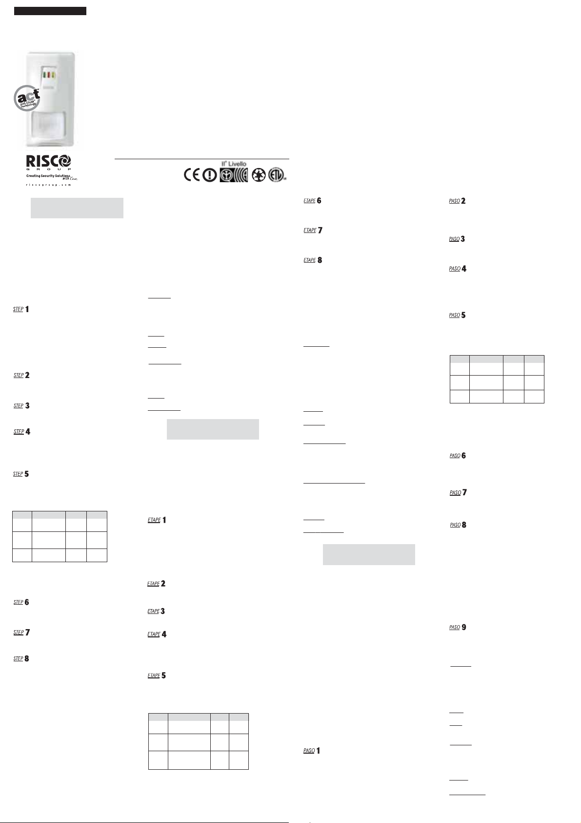
MOUNTING HEIGHT AND SCALE POSITION
BASED ON ROOM SIZE:
Product Mounting Height LONG SHORT
RK810DT 2.1m-2.7m 10m 6m
(6'11"-8’10") (33') (19'8")
RK815DT
2.1m-2.7m 15m 6m
(6'11"-8’10") (
RK825DT
Note: For corridor lens, set position to “LONG”
and use the mounting height of 2.5m for all types of detectors
FINE TUNING OF THE PROTECTED AREA:
Slide the board upwards - to lower the beams and reduce the range.
Slide the board downwards - to raise the beams and increase the range.
When completed, fasten the screw to secure the PCB in the desired position.
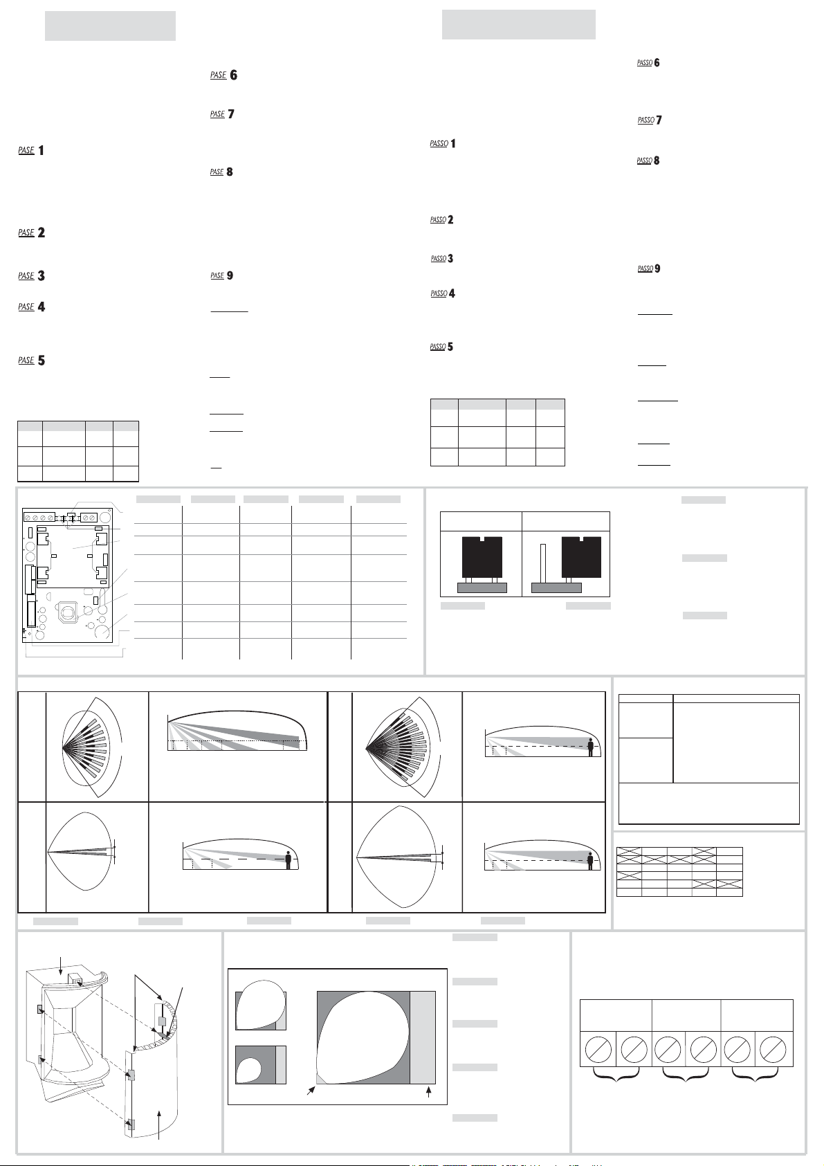
TERMINAL WIRING (See Fig. 6)
Connect the cable to the terminal block at the top of the PCB as follows:
12 VDC: Power supply input.
ALARM: Normally closed output.
TAMPER: Normally closed dry output.
JUMPER SETTING
The iWISE has two jumpers that can either be in (used) or out (unused).
Unused jumpers should be placed on one pin only to prevent their loss.
See Fig 2.
WALK TEST
NOTE:
Two minutes after applying power (warm-up period), walk test the
Detector over the entire protected area to verify proper operation
of the unit. The RK825DT needs a longer warm-up period of FOUR
minutes, which enables a powerful long range sensing capability
with increased sensitivity.
• The MW range can be adjusted by using the potentiometer,which is
located at the bottom of the PCB. It is important to set the potentiometer
to the lowest possible setting that will still provide enough coverage for
the entire protected area, and then to make a walk test near/under the
detector and (if required), to re-adjust the potentiometer. (see Fig 5)
Do not use ACT™ mode in long range /corridor applications if you are
expecting that there will be moving objects behind or on the side of the
required protected area (the corridor) Refer to Fig 5.
FCC NOTE:
This device complies with Part 15 of the FCC Rules. Operation is
subject to the following two conditions:
1. This device may not cause harmful interference and
2. This device must accept any interference received, including
interference that may cause undesired operation.
FCC ID: JE4CSMDT
This equipment has been tested and found to comply with the limits
for a Class B digital device, pursuant to Part 15 of the FCC rules.
These limits are designed to provide reasonable protection against
harmful interference in a residential installation. This equipment
generates, uses and can radiate radio frequency energy and, if not
installed and used in accordance with the instructions, may cause
harmful interference to radio communications.
49'2"
) (19'8")
m0.2-m8.1
m52
)"7’6-"11'5(
)'28(
However, there is no guarantee that interference will not occur in a particular
installation. If this equipment does cause harmful interference to radio or television
reception, which can be determined by turning the equipment off and on, the user is
encouraged to try to correct the interference by one or more of the following measures:
a) Reorient or relocate the receiving antenna.
b) Increase the separation between the equipment and receiver.
c) Connect the equipment to an outlet on a circuit different from that
to which the receiver is connected.
d) Consult the dealer or an experienced radio/TV technician.
FCC WARNING:
The manufacturer is not responsible for any radio or TV interference caused by
unauthorized modifications to this equipment. Such modifications could void the
user's authority to operate the equipment.
ETL UL639 Compliance:
Connect the detector to a power source capable of supplying at
least 4h of Standby power. For bank vaults installation, connect to
a power source capable of supplying at least 72h of standby power
SPECIFICATIONS
ELECTRICAL
Current consumption: 19mA at 12 VDC
38mA at 16 VDC
(MAX with all LED's ON)
Voltage requirements: 9-16 VDC*
Alarm contacts: 24 VDC, 0.1A
Tamper contacts: 24 VDC, 0.1A
OPTICAL
Filtering: White Light Protection
PHYSICAL
Size: 127.6 x 64.2 x 40.9mm
(5 x 2.5 x 1.6 in.)
ENVIRONMENTAL
RF immunity According to EN50130-4
Operating temperature: -20ºC to 55ºC (-4ºF to 131ºF)
Storage Temperature: -20ºC to 60ºC (-4ºF to 140ºF)
* Power to be supplied by 5A max. power source using safety
approved wires, with a min. Gauge of 20AWG.
FOR IMQ
Operating temperature: 5ºC TO 40ºC (41ºF TO 104ºF)
FOR IMQ LEVEL 2
Use the RA91T000000A Swivel
FRANÇAIS
DESCRIPTION GÉNÉRALE
iWISE DT: Détecteur à double technologie - technologies MW
et IR - comportant un mode ACT™ et indication de panne.
AFFICHAGE À DIODES LED
Lorsque le cavalier LED est allumé (ON):
• La diode LED JAUNE indique une détection PIR,
• La diode LED VERTE indique une détection MW,
• La diode LED ROUGE indique une alarme
• Au moment de la mise sous tension, les diodes LED clignotent continuellement,
l'une après l'autre, jusqu'à la fin de la séquence d'échauffement.
• Si la diode LED VERTE s'allume, elle indique une panne du canal MW.
• Si la diode LED JAUNE s'allume, elle indique une panne du canal PIR.
INSTALLATION
CONSIDERATIONS PREL IMINAIRES
Avant l'installation, étudiez avec soin l'espace à protéger afin de choisir
l'emplacement exact de l'appareil et de la lentille pour obtenir la meilleure
couverture possible du point de vue des dimensions. Il est recommandé de
procéder à des installations en coin. Le détecteur doit être installé de sorte que
les divers faisceaux se situent à 45 (optimal) du passage supposé de l'intrus.
Consultez la Fig.3 et l’étape n° 5 pour vous guider.
ATT EN TIO N! L'APPAREIL NE DOIT PAS ÊTRE MONTÉ EN EXPOSITION
DIRECTE À LA LUMIÈRE DU SOLEIL NI À PROXIMITÉ DE SOURCES DE
CHALEUR. LES ZONES DE DÉTECTION DOIVENT ÊTRE DIRIGÉES SOIT VERS
UN MUR SOIT VERS LE SOL (ET NON VERS UNE FENÊTRE NI VERS DES RIDEAUX).
À INSTALLER SUR SURFACES LISSES SEULEMENT.
OUVERTURE DU COUVERCLE FRONTAL
Pour ouvrir le couvercle frontal, effectuez 3 tours complets de vis dans le sens inverse
des aiguilles d'une montre. Une fois la vis relâchée, appuyez-la pour dégager le
couvercle frontal. Si vous n'utilisez pas de vis de maintien, appuyez sur la languette
située derrière le trou de la vis. Vous pouvez à présent retirer le couvercle frontal.
RETRAIT DU TABLEAU PC
Dévissez la vis de maintien qui est située sur le côté droit du PCB (PC Board) et faites
glisser le PCB jusqu’à ce que la vis entre dans l'ouverture élargie. Le PCB peut
maintenant être soulevé et retiré.
MONTAGE
Le iWISE DT peut être monté soit une surface plane soit angulaire.
a. Ouvrez les trous situés sur le couvercle arrière.
b. Introduisez le câble dans l'ouverture qui lui est destinée.
c. Installez le couvercle arrière à sa place finale.
d. Bouchez les trous restants avec du mastic.
e. Après avoir monté le couvercle arrière, remettez le PCB dans la position souhaitée.
RÉGLAGE DU TABLEAU PC
Après avoir monté la base du détecteur, réinstallez le PCB. Pour choisir le réglage
vertical qui convient à la LENTILLE GRAND ANGLE installée à une hauteur située
entre 2.1m et 2.7m (6’11” - 8’10”), utilisez l'échelle de grandeur indiquée sur le
côté inférieur gauche du PCB comme suit:
POSITION DE L'ÉCHELLE BASÉE SUR LES
DIMENSIONS DE LA PIÈCE POUR RK115D ET
Produit Hauteur de montage LONG
RK810DT 2.1m-2.7m 10m 6m
(6'11"-8’10") (33') (19'8")
2.1m-2.7m 15m 6m
RK815DT
(6'11"-8’10") (
RK825DT
Note : Pour les lentilles rideau, positionner le détecteur sur “LONG” et utiliser
une hauteur de montage de 2,5m pour tous les types de détecteurs.
SYNTONISATION DE LA ZONE PROTÉGÉE:
Faites glisser le tableau vers le haut - pour abaisser les faisceaux et réduire la portée.
Faites glisser le tableau vers le bas - pour élever les faisceaux et augmenter la portée.
Ensuite, serrez la vis pour fixer le PCB dans la position voulue.
m0.2-m8.1
)"7’6-"11'5(
49'2"
) (19'8")
m52
)'28(
COURT
CÂBLAGE DES TERMINEAUX (Cf. Fig. 6)
Connectez le câble au bloc du terminal en haut du PCB comme suit:
12 VDC: Entrée de l'alimentation électrique.
ALARME: Sortie normalement fermée.
AUTOPROTECTION: Sortie sèche normalement fermée.
INSTALLATION DES CAVALIERS
Le iWISE dispose de deux cavaliers qui peuvent être en positon de marche
(IN - en utilisation) ou en position fermée (OUT - hors utilisation). Les
cavaliers inutilisés doivent être placés sur une broche dans le seul but d'éviter
de les perdre. Cf. Fig. 2
TEST DE PASSAGE À PIED
Deux minutes après avoir réalisé la mise sous tension (séquence d'échauffement),
faites un test de passage à pied pour vérifier l'efficacité du détecteur sur la
totalité de la zone protégée. Le RK825DT nécessite une période d'échauffement
plus longue allant jusqu’ à QUATRE minutes, ce qui permet une capacité de
captage puissante sur longue portée avec sensibilité accrue.
REMARQUE:
• Assurez-vous de remettre en place le couvercle frontal avant d'effectuer le
test de passage.
• La portée MW peut se régler à l'aide du potentiomètre situé au bas du PCB. Il
est très important de régler le potentiomètre sur le niveau le plus bas possible
permettant de couvrir la totalité de la surface de la zone àprotéger. N'utilisez
pas le le mode ACT™ en application longue portée /couloir si vous prévoyez le
passage d'objets derrière ou à côté de la zone àprotéger (le couloir). Cf. Fig.5
SPÉCIFICATIONS
ELECTRIQUES
Consommation (sous 12 VDC)
Hors alarme: 19mA
En alarme: 38mA à 12 VDC (44mA à 12 VDC pour RK825DT)
Voltage exigé: 9-16 VDC
Contacts d'alarme: 24 VDC, 0.1A.
Temps minimal de changement d’état: 2.2 seconds
Contacts d'autoprotection : 24 VDC, 0.1A
Résistance de la boucle de Détection: Etat ouvert: plus que 10
Etat fermé: moins que 1 ohm
Ondulations résiduelles
maximales admissibles: 0.25V créte à créte
OPTIQUES
Filtrage: Protection lumière blanche
PHYSIQUES
Dimensions: 127.6 x 64.2 x 40.9mm
(5 x 2.5 x 1.6 in.)
ENVIRONNEMENTALES
Immunité RF Répond à la norme EN50130-4
Température de fonctionnement: -20°C to 55°C (-4°F à 131°F)
Température de stockage: -20°C to 60°C (-4°F à 140°F)
Indice de protection: IP 31/IK 02
Taille du càble à utiliser: Fil de diamètre au moins 0.5 mm pour une longueur ne
dépassant pas 300 mètres.
ORGANISME DE CERTIFICATION:
AFNOR CERTIFICATION: 11 rue Francis de Pressensé
93571 LA PLAINE SAINT-DENIS Cedex
http://www.marque-nf.com
CNPP: BP 2265, 27950 ST MARCEL,
http://www.cnpp.com
POUR IMQ:
Température de fonctionnement : 5° C à 40° C (41° F à 104° F)
POUR IMQ NIVEAU 2:
Utilisez le pivot RA91T000000A
8
ESPAÑOL
DESCRIPCION GENERAL
• iWISE DT: Detector DSP de Tecnología Dual ofreciendo ambas tecnologías MW e
IR que incluyen ACT™ e indicación de fallas.
CARACTERISTICAS DEL iWISE DT
• Tecnologías Dual IR y MW
• ACT™ - Tecnología Anti - Cloak
• Cobertura -10/15/25m (33/50/82 ft)
• montaje flexible de altura – hasta 2.7m (8’10”)
• Indicación de fallas
• Zona de Sabotaje
• Compensación de Temperatura Verdadera (Patentada)
• Ajuste del alcance por microondas
• Lentes Pigmentadas para filtración de luz blanca
• Bajo consumo de corriente
• Alta Inmunidad de RF 30V/m
•Procesamiento de señal de interferencia antifluorescente
• Amplio espacio de cableado
•Optimización del alcance por medio de PCB móvil
• Eslabón giratorio en la unión pared/rincón o en el techo
(con tamper de pared – opcional)
INDICADORE DEL LED
Cuando el cable de conexión del LED está en posición ON:
• LED AMARI LLO indica detección PIR
• LED VERDE indica detección MW
• LED ROJO indica alarma
• En el periodo del ciclo inicial, los LEDs van a centellear continuamente, uno
después del otro, hasta el final de periodo de calentamiento.
• LED VERDE intermitente indica problemas en el canal MW.
• LED AMARILLO intermitente indica problemas en el canal PIR.
INSTALLATIÓN
CONSIDERACIONES PRELIMINARES
Antes de la instalación, estudie el espacio a ser cuidadosamente, para
poder elegir la mejor ubicación de la unidad y de las lentes para la mejor cobertura
posible. Son recomendadas instalaciones en los rincones. El Detector deberá
ser instalado de tal manera que la dispersión del rayo esté a 45° (óptimo) del
camino previsto del intruso. Use la Fig 3 y el Paso 5 para orientación.
ADVERTENCIA: LA UNIDAD NO DEBE SER MONTADA FRENTE A LUZ SOLAR
DIRECTA O CERCA DE FUENTES DE CALOR. LOS SECTORES DE DETECCION
DEBEN APUNTAR O EN DIRECCION A LA PARED O EN DIRECCION AL PISO.
(NO HACIA VENTANAS O CO RTINAS). INSTALE SOLAMENTE SOBRE
SUPERFICIES LISAS.
Para abrir firmemente la tapa delantera, gire el tornillo 3 vueltas
completas en sentido opuesto a las agujas del reloj. Con el tornillo
aflojado aprételo para a dentro para liberar l a tapa delantera.
Si un tornillo de fijación no es usado, aprete la aleta, que está
ubicada detrás del agujero del tornillo. La tapa delantera puede
ahora ser removida.
Afloje el tornillo de mantenimiento, que está ubicado en el lado
derecho del PCB y deslice el PCB hacia arriba hasta que el tornillo
entre en la apertura ensanchada. El PCB puede ahora ser
desplegado.
El iWISE puede ser montado en una superficie plana o en un rincón.
a.Abrir los agujeros pre-marcados en la tapa posterior.
b.Insertar los cables a través de la apertura para cables.
c.Montar la tapa posterior en su ubicación final.
d.Cerrar los agujeros que quedan con sellante.
e.Después de montar la tapa posterior, retornar el PCB a su posición
deseada.
Después que la base del detector haya sido montada, reinstale el PCB.
Para elegir la posición correcta del ajuste vertical para las LENTES
DE GRAN ANGULAR instaladas a una altura entre 2.1m - 2.7m
(6’11” - 8’10”) use la escala que se encuentra en el lado izquierdo
inferior del PCB, como sigue:
POSICION EN LA ESCALA BASADA EN EL TAMAÑO
DE LA PIEZA PARA
Producto
RK810DT 2.1m-2.7m 10m 6m
RK815DT
ohm
RK825DT
Note:Para la lente de pasillo, colocarlo en la posición “LONG”
y utilizar una altura de montaje de 2,5 m. para todos los tipos
de detector.
AJUSTE DEL AREA PROTEGIDA:
Deslice la placa hacia arriba – para bajar los rayos y reducir el alcance.
Deslice la placa hacia abajo – para levantar los rayos y aumentar
el alcance. Cuando haya completado, aprete el tornillo para
asegurar el PCB en la posición deseada.
Conecte el cable al bloque de la terminal en la parte superior del
PCB como sigue:
12 VDC: Entrada de la fuente de alimentación
ALARMA: Salida normalmente cerrada.
TAMPER: Salida seca normalmente cerrada.
El iWISE tiene dos cables de conexión que pueden estar en in
(usado) o out (sin uso). Los cables de conexión sin uso deben
ser colocados en una clavilla solamente, para evitar su pérdida.
Var Fig. 2
Dos minutos después de activar (periodo de calentamiento), haga
la prueba de movimento con el Detector por toda el área protegida
para verificar si la unidad está funcionando propiamente. El RK825DT necesita un periodo de calentamiento más largo, de
CUATRO minutos, lo que permite una capacidad más poderosa
de sensibilidad a largo alcance, con sensibilidad aumentada.
NOTA:
• Asegúrese de haber recolocado la tapa delantera antes de
ejecutar la Prueba de Caminata.
• El alcance del MW puede ser ajustado usando el potenciómetro,
que está ubicado al fondo del PCB. Es importante poner el
potenciómetro en la regulación más baja posible que todavía
proveerá suficiente cobertura a toda el área protegida. No instale
el Detector en la aplicación de largo alcance/corredor, si Usted
espera que pueden haber objetos móviles detrás o al lado de la
requerida área protegida. (el corredor). Refiérase a la Fig. 5
Después de completar la instalación y las etapas de pruebas,
asegúrese que todos los cables de conexión estén en las posiciones
deseadas. La unidad está ahora preparada para ser usada.
ESPECIFICACIONES
ELECTRICA
Consumo de corriente: 19mA a 12 VDC
38mA a 16 VDC
(MAX con todos LED's ON)
Requisitos de Voltaje: 9-16 VDC
Contactos del Alarma: 24 VDC, 0.1A
Contactos del Tamper: 24 VDC, 0.1A
OPTICA
Filtración: Protección contra Luz Blanca
FISICA
Tamaño: 127.6 x 64.2 x 40.9mm
(5 x 2.5 x 1.6 in.)
AMBIENTAL
Inmunidad RF According a EN50130-4
Temperatura de operación:
Temperatura de Almacenamiento:
PARA IMQ
Temperatura de Operación: 5ºC hasta 40ºC (41ºF hasta 104ºF)
PARA IMQ NIVEL 2:
Use eslabón giratorio RA91T000000A eslabón giratorio
ABRIENDO LA TAPA DELANTERA
REMOVIENDO LA PLACA DEL PC
MONTAJE
AJUSTES DE LA PLACA DEL PC
Altura da Montaje
(6'11"-8’10") (33') (19'8")
CONEXIÓN CABLEADO DE LOS TERMINALES (Var Fig. 6)
JUMPER POSICIONES
PRUEBA DE MOVIMENTO
DISPOSICION FINAL
LONG SHORT
2.1m-2.7m 15m 6m
(6'11"-8’10") (
49'2"
) (19'8")
m0.2-m8.1
m52
)"7’6-"11'5(
)'28(
-20°C hasta 55°C (-4°F hasta 131°F)
-20°C hasta 60°C (-4°F hasta 140°F)
Page 2
ITALIANO
DESCRIZIONE GENERALE
•
iWISE DT: Rivelatore Doppia Tecnologia con Microonda e Infrarosso
con modo di funzionamen to ad Alto Rischio e indicazione di anomalia
a mezzo LED
VISUALIZZAZIONE A LED
Con il ponticello LED inserito:
• Il LED GIALLO indica la rivelazione della sezione PIR.
• Il LED VERDE indica la rivelazione della sezione Microonda.
• Il LED ROSSO indica l’allarme.
• Una volta alimentata l’unità, i LE D lampeggeranno continuamente,
uno dopo l’altro, fino al termine del periodo di pre-riscaldamento.
• LED VERDE lampeggiante indica anomalia del canale microonda
• LED GIALLO lampeggiante indica anomalia del canale infrarosso
INSTALLAZIONE
CONSIDERAZIONI PRELIMINARI
Prima dell’installazione, studiare attentamente l’area da proteggere in modo
da scegliere la corretta posizione del sensore per la migliore copertura della
lente. Le installazioni ad angolo sono raccomandate. Il rivelatore dovrebbe
essere installato in modo che i fasci siano a 45° (ottimale) rispetto al
percorso previsto dall’eventuale intruso. Vedere Fig. 3 e consultare la Fase
5 per l’installazione.
ATTENZI ON E:
ALLA LUCE DIRETTA DEL SOLE O VICINO A SORGENTI DI CALORE.
I SETTORI DI RIVELAZIONE DOVREBBERO ESSERE PUNTATI VERSO
IL MURO O IL PAVIMENTO (NON VERSO
INSTALLARE SOLO SU SU PERFICI PIANE.
Per aprire il coperchio del sensore girare la vite in senso antiorario per 3 volte
Premere leggermente la vite allentata verso l’interno e rimuovere il coperchio.
Se non è stata utilizzata la vite, premere leggermente verso l’inte rno del
sensore la linguetta plastica posizionata dietro il foro della vite e rimuovere
il coperchio.
Allentare la vite di fissaggio situata nella parte destra della scheda e far
scorrere verso l’alto la scheda finché la vite non raggiunge il foro di
uscita circolare. La scheda può ora essere rimossa.
iWISE DT può essere montato sia su una superficie piana che in un angolo.
a. Aprire i fori nella parte posteriore del contenitore
b.Far passare il cavo attraverso il foro di passaggio cavi
c.Montare la parte posteriore del contenitore nella posizione desiderata
d. Sigillare i fori non utilizzati
e. Dopo aver montato la parte posteriore del contenitore, sistemare
Dopo aver montato la parte contenitore del contenitore, rimontare la scheda
elettronica. Con le lenti GRANDANGOLO e il rivelatore installato a
un’altezza compresa tra i 2.1 e 2.7 metri, utilizzare la scala serigrafata
nella parte superiore sinistra della scheda elettronica del rivelatore per
scegliere la corretta posizione della stessa in funzione dell’area da
proteggere. Consultare le tabelle che seguono:
POSIZIONE DELLA SCALA BASATA SULLA GRANDEZZA
DELLA STANZA DA PROTEGGERE
RK810DT 2.1m-2.7m 10m 6m
RK815DT
RK825DT
L’UNITA’ NON DEVE ESSERE MONTATA DI FRONTE
CONSIDERAZIONI PRELIMINARI
RIMOZIONE DELLA SCHEDA ELETTRONICA
MONTAGGIO
la scheda elettronica nella posizione desiderata
REGOLAZIONE DELLA SCHEDA ELETTRONICA
Prodotto
Altura da Montaje
(6'11"-8’10") (33') (19'8")
2.1m-2.7m 15m 6m
(6'11"-8’10") (
FIG 1.
TAMPE R+ - LEDS ON ALARM C29
TB1
+5V
MU1
C15
C28
NV2
FL
IF
NV2
T4
C19
S1
C6
C25
LONG
C8
SHORT
LONG SHORT
49'2"
) (19'8")
m0.2-m8.1
m52
)"7’6-"11'5(
)'28(
+
GND
XTL1
+ -
GND
TC1
J1
ON-ACT ON
OFF-ACT OFF
C1
C21
C24
MICROWAVE
SENSITIVITY
MIN MAX
FINESTRE O TENDE).
ENGLISH
LED's jumper
LEDS
MW Module
ACT ON/O FF
Jumper
PIR Sensor
MW range
adjustment
Tamper Switch
Range Marking
adjustment
FRANÇAIS
Cavalier LED
Diodes LED
Module
Micro-ondes
Cavalier de haut
risque/risque
normal
Senseur PIR
Réglage de
portée MW
Bouton
d'auto-protection
Réglage du marquage
de portée
Note: per installazioni con lente a corridoio, selezionare la posizione “LONG”
e utilizzare l’altezza di installazione 2.5m per tutti i modelli di rivelatori.
REGOLAZIONE FINE DELLA COPERTURA DELLE LENTI:
Far scorrere la scheda verso l’alto per abbassare i raggi e ridurre la portata.
Far scorrere la scheda verso il basso per alzare i raggi e incrementare la
portata. Una volta completate queste operazioni, stringere la vite in modo da
assicurare la scheda elettronica nella posizione desiderata.
CABLAGGIO MORSETTIERA (Vedere Fig. 6)
Cablare la morsettiera posizionata nella parte superiore del sensore come segue:
12 VDC: Ingresso dell’alimentazione
ALARM: Contatto di allarme normalmente chiuso
TAMPER: Contatto di manomissione normalmente chiuso
PREDISPOSIZIONE DEI PONTICELLI
Il iWISE ha due ponticelli che possono essere inseriti (IN) o estratti (OUT)
I ponticelli estratti (OUT) dovrebbero essere posizionati su di un solo
pin per evitarne la perdita. Vedere Figura 2.
LED: IN - Tutti i LED abilitati
LED: OUT - Tutti i LED disabilitati
ACT: IN - Funzione ACT attiva (configurazione di fabbrica)
ACT: OUT - Funzione ACT esclusa
PROVA DI MOVIMENTO
Dopo aver atteso un periodo di riscaldamento di 2 minuti dalla alimentazione,
effettuare la prova di copertura del sensore. Muoversi all’i nterno d ell’area d a
proteggere e verificare che l’unità si attivi correttamente. Il modello RK-825
necessi ta di un periodo di riscaldamento maggiore (4 minuti), che permette di
aumentare la sensibilità del sensore e, di conseguenza, la copertura.
NOTE:
Assicurarsi di aver richiuso il coperchio del rivelatore prima di eseguire la
prova di movimento. La portata della Microonda può essere regolata me diante il
potenziometro localizzato nella parte inferiore della scheda elettronica. E’ importante
regolare il potenziometro al minimo e successivamente variarlo per garantire sufficiente
copertura per tutta l’area da proteggere. In ogni caso il potenziometro va tenuto al
valore minimo possibile. Non utilizzare la funzione ACT™ se il rivelatore è installato
in applicazioni a lunga portata o corridoio e si prevede la presenza di oggetti in
movimento dietro o ai lati dell’area da proteggere (il corridoio). Vedere Fig. 5:
CONFIGURAZIONE FINALE
Dopo aver completato l’installazione e la fase di test, assicurarsi ch e tu tti i
ponticelli siano nella posizione desiderata. L’unità è ora pronta all’uso.
SPECIFICHE TECNICHE
ELETTRONICA
Assorbimento massimo di corrente:
19mA a 12 V---, 38mA a 16 V--- (MASSIMO con tutti i LE D accesi)
Tensione nominale di alimentazione: da 9 a 16 V---
Massima potenza irradiata: 10 mWatt E.I.R.P.
Frequenza microonda: 10.525 Ghz.
Contatti allarme: 24 V---, 0.1A
Contatti tamper: 24 V---, 0.1A
Tipo di segnale MW: Pulsato
OTTICA
Filtro: Protezione dalle luci bianche
Numero di zone sensibili:
Lente standard: 30 zone su 4 piani + 1 antiavvicinamento
Lente RL-15: 2 zone su 2 piani + 1 antiavvicinamento
DIMENSIONI
127.6 x 64.2 x 40.9mm
AMBIENTALI
Immunità RF Conforme alla normativa EN50130-4
Temperatura di funzionamento: da -20°C a 5°C
Temperatura di stoccaggio: da -20°C a 60°C
Temperature di funzionamento certificate: da +5°C a +40°C;
IMQ
Temperatura di funzionamento: da 5ºC a 40º
º
livello di prestazione usare lo snodo RA91T000000A
Per il 2
SPANISH
Cable de conexión
del LED
LED’s
Módulo de
Microondas
ACT ON/O FF
puente
Sensor PIR
Ajuste del Rango
de MW
Conmutador
Tamper
Marca de Ajuste del
Alcance
ITALIANO
LED
Ponticello LED
Modulo
Microonda
Ponticello Normale/Alto
Rischio
Sensore PIR
Regolazione sensibilit
Microonda
Interrutore tamper
Regolazione verticale
della scheda
P O R T U G U Ê S
Cabo de conexão
do LED
LEDS
Módulo de
Microondas
ACT on/off
Jumper
Sensor PIR
Ajuste do
Alcance do MW
Comutador Tamper
Marca de Ajuste do
Alcance
DESCRIÇÀO GERAL
A familia IWISE indui os seguintes modelos:
• iWISE DT: Detector de Tecnología Dual ofreciendo as
tecnologías de IR que incluyen ACT™ e indicación de fallas.
LED
Quando o Jumper LED estiver na posição ON:
• O LED AMARELO indica detecção do PIR
• O LED VERDE indica detecção do MW
• O LED VERMELHO indica alarme
• Ao conectar, os LEDs piscarão continuamente, um
depois do outro, até o fim do período de aquecimento.
• LED VERDE piscando indica problemas no canal MW.
• LED AMARELO piscando indica problemas no canal PIR.
INSTALAÇÃO
Antes da instalação, estude cuidadosamente o espaço a ser protegido para
escolher o local exato de instalação da unidade e a lente para a melhor cobertura
possível. São recomendadas instalações de canto. O Detector deverá ser instalado
de modo a formar um ângulo de 45º (otimizado) no possível caminho do intruso.
ATENÇÃO:
A UNIDADE NÃO DEVERÁ SER MONTADA DIRETAMENTE PARA A LUZ SOLAR OU
PRÓXIMA DE QUALQUER FONTE DE CALOR. OS SETORES DE DETECÇÃO DEVEM
SER APONTADOS PARA UMA PAREDE OU PARA O CHÃO (NUNCA PARA JANELAS
NEM CORTINAS). SÓ INSTALE EM SUPERFÍCIES LI SAS.
Para abrir a tampa dianteira, vire o parafuso 3 voltas completas à esquerda.
Com o parafuso solto, aperte- o para dentro para liberar a yampa dianteira.
Se um parafuso de trava não for usado, pressione, a aba que fica situada atrás
do furo do parafuso. A tampa dianteira pode ser removida agora.
Solte o parafuso de segurança que está situado do lado do mão do PCB e
deslize o PCB até que o parafuso entre nas aberturas ampliadas O PCB pode
ser retirado agora.
O iWISE DT pode ser montado em uma superfície plana ou em um canto.
a. Abra os buracos pré- marcados na tampa traseira.
b. Insira o cabo pela abertura de cabo.
c. Monte a tampa traseira em seu local final.
d. Sele os buracos restantes com selante (cola).
e. Depois de montar a tampa traseira, coloque a PCB em sua posição desejada.
Depois que a base de Detector estiver montada, reinstale a PCB. Para escolher
a posição correta de ajuste vertical para LENTE DE ÂNGULO ABERTO instalado
a uma altura entre 2.1m - 2.7m (6'11" - 8'10") use a escala do lado inferior
esquerdo da PCB como segue:
POSIÇÃO DE ESCALA BASEADA NO
TAMANHO DO LOCAL;
Producto
RK810DT 2.1m-2.7m 10m 6m
RK815DT
RK825DT
Nota: Para lentes de corredor, ajuste a posição para “LONG”e aplique a
altura de instalação de 2,5m para todos os tipos de detectores.
PORTUGUÊS
CONSIDERAÇÕES PRELIM INARES
ABERTURA DA TAMPA DIANTEIRA
REMOVENDO A PLACA DE PC
MONTAGEM
AJUSTE DA PLACA DE PC
Altura da Montaje
(6'11"-8’10") (33') (19'8")
FIG 2.
FRANÇAIS
Diodes LED en position I N (en marche)
- active toutes les diodes LED
Diodes LED en position OUT (à l'arrêt)
- désactive toutes les diodes LED
ACT: IN - ( ACT en marche)
ACT: OUT - (ACT à l`arreêt) (réglage d’usine)
LONG SHORT
2.1m-2.7m 15m 6m
(6'11"-8’10") (
IN
49'2"
) (19'8")
m0.2-m8.1
m52
)"7’6-"11'5(
)'28(
OUT
ENGLISH
Jumper positions
LEDS IN - Enables all LEDs
LEDS OUT - Disables all LEDs
ACT: IN - ACT ON
ACT: OUT - ACT OFF (Factory Settings)
AJUSTE DA ÁREA PROTEGIDA
Deslize a placa para cima - Deslize a placa para cima - abaixar
linhas e reduzir o alcance. Deslize a placa para baixo – subir as
linhas e aumentar o alcance. Quando completad a, aperte o parafuso
para segurar a PCB na posição desejada.
LIGAÇÃO DOS TERMINAIS (veja Fig 6)
Conecte o cabo ao bloco de terminais no topo da PCB como
segue:
1 2 VDC: Entrada da fonte de alimentação.
ALARME: Saída Normalmente Fechada.
TAMPE R: Saída de contato seco normalmente fechada.
COLOCAÇÃO DOS JUMPERS
O iWISE tem dois jumpers que podem estar na posição “in” (usado)
ou ‘out’ (não usado). Os jumpers não usados devem ser colocados
em um só do s pinos para evitar a sua perda deles. Veja Fig. 2.
TESTE DA CAMINHADA
Dois minutos depois ativar (período de aquecimento), caminhe para
testar o Detector através de toda a área protegida para verificar a
correta operação da unidade. O RK- 825 precisa um período mais
longo de aquecimento de QUATRO minutos que habilitam uma
poderosa capacidade de longo alcance com sensibilidade aumentada.
NOTA: Assegure- se de ter colocado a cobertura dianteira antes
de fazer o Teste da Caminhada O alcance do MW pode ser ajustado
usando o potenciômetro, que fica situado ao fundo do PCB. É
importante ajustar o potenciômetro para a mais baixa posição
possível que ainda proporcione suficiente cobertura a toda a área
protegida. Não use o modo ACT™ em aplicações de longo alcance/
corredor se você está esperando que haja objetos móveis atrás ou no
lado da área protegida exigida (o corredor).Refira- se a Fig. 5
ORGANIZAÇÃO FI NAL
Depois de completar a instalação e efetuar os testes,
assegurese de que todos os jumpers estão nas posições
desejadas. A unidade está agora pronta para ser uso.
ESPECIFICAÇÕES
ELÉTRICAS
Consumo de corrente: 19mA a 1 2 VDC
38mA a 16 VDC
(O MAX com LED Ligados)
Exigências de voltagem: 9- 16 VDC
Contatos de alarme: 24 VDC, 0.1A,
Contatos do Tamper: 24 VDC, 0.1A,
ÓPTICAS
Filtragem: Proteção contra Luz Branca
FÍSICAS Dimensões: 1 27.6 x 64.2 x 40.9mm
AMBIENTAIS
Imunidade a RF Conformar-se a EN50130-4
Temperatura operacional: -20º C a 55ºC
(- 4º F a 131º F)
Temperatura de armazenamento: -20º C a 60º C
(- 4º F a 140º F)
PARA IMQ
Temperatura de Operação: 5ºC até 40ºC
(41º F até 104º F)
PARA IMQ
Use suporte giratório RA91T000000A suporte giratório
(5 x 2.5 x 1.6 em.)
SPANISH
Posiciones de los Cables de Conexión
LEDS IN - Activa todos los LEDs
LEDS OUT - Desactiva todos los LEDs
ACT: IN - ACT ON
ACT: OUT - ACT OFF (Factory Settings)
ITALIANO
Posizione dei ponticelli
LED ON - Tutti i LED abilitati
LED OFF - Tutti i LED disabilitati
ACT: IN - ACT ON
ACT: OUT - ACT OFF (Factory Settings)
P O R T U G U Ê S
Posições de Jumper
LEDS EM - Habilita todo o LEDs
LEDS FORA - Incapacita todo o LE Ds
ACT: IN - ACT ON
ACT: OUT - ACT OFF (Factory Settings)
FIG 3.
WIDE ANGLE (RL115D)
CORRIDOR (RL15)
FIG 4.
RK810DT/815DT
RK810DT/815DT
ENGLISH
Sleeve
DT Len ses
98º
1.3 m /2 m
(4'3")/(6'7")
FRANÇAIS
Cut
Corners
2.5m
(8'2")
1.1m
(3'7")
0.4m
2.1m
(1'4")
(6'9")
(11'5")
2.5m
(8'2")
1.1m
(3'7")
0.4m
(1'4")
Lentilles DT
Short Pin
(Facing upwards)
Lens
3.5m
2.5m
(8'2")
5.4m
(17'6")
FIG 5.
13 . 5 m
(44'3")
10m/15m
(33'/49'2")
ITALIANO
10m/15m
(33')/(49'2")
Lenti iWISE DT
1
2
3
WIDE ANGLECORRIDTR
RK825DT (RL125H)
RK825DT (RL1 7)
SPANISH
(6'7")
1.1m
83º
(3'7")
2.5m
(8'2")
3m
1.1m
(3'7")
Lentes del DT
ENGLISH
MW range adjustment
1
. Over power2. Under power
3
. Detector4. Corridor
FRANÇAIS
Réglage de portée MW
1
. Surpuissance 2. Puissance insuffisante
3
. Détecteur4. Couloir
SPANISH
Ajuste del alcance del MW
1
. Exceso de energia 2. Menos energia
3
. Detector 4. corridor
ITALIANO
Regolazione ottimale della portata della
Microonda
1
4
. Troppo 2. Poco
3
. Rivelatore 4. Corridoio
P O R T U G U Ê S
MW ajuste de alcance otimizado
1.
Alto Alcance 2.Baixo Alcance
3.
Detector
2m
0.4m
(1'4")
(9'10")
0.4m
(1'4")4m(13'1")
P O R T U G U Ê S
4.
Corredor
3m
WEIV EDISWEIV POTWEIV EDISWEIV POT
(75'5")
Lentes del iWISE DT
Figure 6.
Terminal Wiring
TABLE 2: iWISE Product Part Numbers
PRODUCT P/N
RK810DT00xxA
RK815DT00xxA
RK825DT00xxA
iWISE Accessories
RA91T000000A
RA910000000A
RA900000000A
25m
RL15
(82')
RL17
xx
according to the following list:
00 - 10.525GHz
UK - 10.687GHz
FR - 9.9GHz
DE - 9.35GHz
Table for P/N: RK810DT0000A, RK815DT0000A, RK825DT0000A
AT BE CY CZ DK
EE FI
HU IE IT
23m
LU
SE SL ES SK GB
BG RO
P/N: RK810DT00FRA, RK815DT00FRA, RK825DT00FRA can be used only in: AT, CZ,EE, FI, FR
RK810DT00UKA, RK815DT00UKA, RK825DT00UKA-
P/N:
can be used in the UK only
DESCRIPTION
iWISE DT 10m with ACT™
iWISE DT 15m with ACT™
iWISE DT 25m with ACT™
iWISE Wall Swivel with back tamper
iWISE Wall/Corner Swivel
iWISE Ceiling Swivel
Corridor lens for RK810DT, RK815DT
Long Range lens for RK825DT
- Microwave X-Band Frequency, select
FR DE
MT NL PL
LV
+ 12 - ALARM TAMPER
To DC power
supply
To available
zone
GR
LT
PT
To available
zone
 Loading...