

Page 1
TM
iWISE
Models: RK815DTG3
RK825DTG3
U.S. Patent Number:
This product is protected under Patent No. US 7,126,476 B2. Other patents pending.
CE Compliance Section (European and German versions):
Risco Ltd. hereby declares that this equipment is in compliance with the essential
requirement and other relevant provisions of Directive 1999/5/EC. For the CE Declaration
of Conformity please refer to our website: www.riscogroup.com
Ce produit répond aux exigences du référentiel de certification NF324-H58 pour la
classification 3 boucliers.
RK815DTG3/RK825DTG3 applicable countries (European version):
AT BE CY CZ DK
EE FI
HU IE IT
LU
SE SL ES SK GB
BG RO TR CH NO
RK815DTG3/RK825DTG3 applicable countries (German Version):
AT, CZ, SL, DE, TR, RU, EE
RK815DTG3/RK825DTG3 FCC compliance Section (US version):
FCC Part 15 Note:
This equipment has been tested and found to comply with the limits for a Class B digital
device, pursuant to Part 15 of the FCC rules. These limits are designed to provide
reasonable protection against harmful interference in a residential installation. This
equipment generates, uses and can radiate radio frequency energy and, if not installed
and used in accordance with the instructions, may cause harmful interference
to radio communications.
However, there is no guarantee that interference will not occur in a particular installation.
If this equipment does cause harmful interference to radio or television reception, which
can be determined by turning the equipment off and on, the user is encouraged to try to
correct the interference by one or more of the following measures:
• Reorient or relocate the receiving antenna.
• Increase the separation between the equipment and receiver.
• Connect the equipment to an outlet on a circuit different from that to which the receiver
is connected.
• Consult the dealer or an experienced radio/TV technician.
FR DE
MT NL PL
LV
EN50131-1 Grade 3*
EN50131-2-4 Grade 3*
EN50131-6 Type C
EN50130-5 Class II
EN50130-4
* Grade 2 when installed with swive
GR
LT
PT
s
FCC Warning:
The manufacturer is not responsible for any radio or TV interference caused by
unauthorized modi¿cations to this equipment. Such modi¿cations could void the user's
authority to operate the equipment.
FCC ID: JE4CSMDT
RISCO Group Limited Warranty
RISCO Group and its subsidiaries and af¿liates ("Seller") warrants its products to be free
from defects in materials and workmanship under normal use for 24 months from the
date of production. Because Seller does not install or connect the product and because
the product may be used in conjunction with products not manufactured by the Seller,
Seller cannot guarantee the performance of the security system which uses this product.
Seller's obligation and liability under this warranty is expressly limited to repairing and
replacing, at Seller's option, within a reasonable time after the date of delivery, any
product not meeting the speci¿cations. Seller makes no other warranty, expressed or
implied, and makes no warranty of merchantability or of ¿tness for any particular
purpose. In no case shall seller be liable for any consequential or incidental damages for
breach of this or any other warranty, expressed or implied, or upon any other basis of
liability whatsoever.
Seller's obligation under this warranty shall not include any transportation charges or
costs of installation or any liability for direct, indirect, or consequential damages or delay.
Seller does not represent that its product may not be compromised or circumvented; that
the product will prevent any personal injury or property loss by burglary, robbery, ¿re or
otherwise; or that the product will in all cases provide adequate warning or protection.
Seller, in no event shall be liable for any direct or indirect damages or any other losses
occurred due to any type of tampering, whether intentional or unintentional such as
masking, painting or spraying on the lenses, mirrors or any other part of the detector.
Buyer understands that a properly installed and maintained alarm may only reduce the
risk of burglary, robbery or ¿re without warning, but is not insurance or a guaranty that
such event will not occur or that there will be no personal injury or property loss as a
result thereof. Consequently seller shall have no liability for any personal injury, property
damage or loss based on a claim that the product fails to give warning. However, if seller
is held liable, whether directly or indirectly, for any loss or damage arising under this
limited warranty or otherwise, regardless of cause or origin, seller's maximum liability
shall not exceed the purchase price of the product, which shall be complete and
exclusive remedy against seller. No employee or representative of Seller is authorized to
change this warranty in any way or grant any other warranty.
WARNING: This product should be tested at least once a week.
CAUTION: risk of explosion if battery is replaced by an incorrect type.
Dispose of used batteriess according to local regulations.
© RISCO Group 01/2013 5IN1255 F
RISCO Group Contacting Info
RISCO Group is committed to customer
service and product support. You can contact
us through our website (www.riscogroup.com)
or at the following telephone and fax numbers:
UK Tel: 44-(0)-161-655-5500
support-uk@riscogroup.com
ITALY Tel: +39-02-66590054
support-it@riscogroup.com
SPAIN Tel: +34-91-490-2133
support-es@riscogroup.com
FRANCE Tel: +33-164-73-28-50
support-fr@riscogroup.com
BELGIUM Tel: +32-2522-7622
support-be@riscogroup.com
U.S.A Tel: +1-631-719-4400
support-usa@riscogroup.com
BRAZIL Tel: +55-11-3661-8767
support-br@riscogroup.com
CHINA (Shanghai)
Tel: +86-21-52-39-0066
support-cn@riscogroup.com
CHINA (Shenzhen)
Tel: +86-755-82789285
support-cn@riscogroup.com
POLAND Tel: +48-22-500-28-40
support-pl@riscogroup.com
ISRAEL Tel: +972-3-963-7777
support@riscogroup.com
ENGLISH
The RK815DTG3/RK825DTG3 detectors are the ultimate motion detectors for professional
installations, incorporating both Anti-Mask and Anti-Cloak™ Technologies (ACT™), adhering to new
environmentally friendly guidelines.
RK815DTG3/RK825DTG3 detectors are available in 15m and 25m models, and include built-in
end-of-line (EOL) resistors to simplify installation.
Installation / Maintenance
1. Mounting - The iWISE 815DTG3/825DTG3 can be mounted either on a flat surface or on a wall
corner (corner mounting).
•Using a suitable tool, open the following knockouts on the detector’s base (see Figure 1).
Note: If a back tamper is to be used it is mandatory to screw the tamper back plate to the wall (or
wall corner).
2. To select the correct vertical adjustment position for wide angle lens, use the scale on the bottom
left hand side of the PCB as follows:
Mounting height and scale position based on room size:
Mounting Height L - LONG S - SHORT
For RK815DTG3
2.1m-2.7m (6'11"-8’10") 15m (50’) 6m (20’)
For RK825DTG3
1.8m-2.0m (5'11"-6’7") 25m (82’) 8m (26’)
Note: For Corridor installations, select position to 'LONG' and mount the detector at 2.5m/8’2” height.
3. Set jumpers (see Jumper Setting section).
IMPORTANT: On the face of the Microwave, you will find a colored dot, this represents the Microwave
channel. When installing two detectors in near locations, it is recommended that these dots (channels)
are not of the same color. Example: Two Red should be avoided
Note: Reset the detector after each change made to the settings.
4. Install the front cover back to its place (in a reverse sequence of the removal.
5. Perform a Walk test (see Walk Test section).
6.
Changing Lenses (see Figure 2).
Terminal Wiring (see Figure 5)
Terminal Description
- 12 + 12VDC Input
ALARM N.C. Relay
TAMPER N.C. Tamper switch
Normally Closed Relay: The FAULT/AM relay opens in the following events:
FAULT/AM
• Detector is masked (Alarm relay is also opened)
• Self test failed
• Input voltage is lower than 8VDC
LED LED operation remote control
When an ”Activation Signal”** is applied to the LED input terminal, all LEDs will
be disabled.
LEDs are enabled if nothing is connected (unless LED jumper is OFF) or 0V/12V
is applied (according to the LED/SET Input Jumper position, 12V or 0V).
Remote SET/UNSET control
SET
SET:If an ”Activation Signal”** is applied, anti-mask detection is disabled (for
Grade 2 configuration).
UNSET: If nothing is connected or 0V/12V is applied (according to the LED/SET
Input Jumper position, 12V or 0V) anti-mask detection is enabled (see also
“Green Line” and “Remote Self Test”
**Activation SignalIf 12VDC is applied, and the LED/SET Input Jumper is on 12v position
0V is applied and LED/SET Input Jumper is on 0V position
Jumper Settings
Jumper Function
SW1-1: LED
Used to determine the operation of the detector’s LEDs
ON:
LEDs are enabled, allowing LED control via the LED input terminal
(Default)
OFF: LEDs are disabled
Used to determine if ACT mode is enabled or disabled
SW1-2: ACT
ACT Enabled
ON
Important: Do not use ACT™ mode if you are expecting that there will be
moving objects outside the required protected area, a corridor for example.
OFF
ACT Disabled.
(Default)
SW1-3: Green Line
The RK815DTG3/RK825DTG3 includes a Green Line feature that follows environmental
guidelines by avoiding surplus emission. This feature disables the MW channel when the
alarm system is “Unset”, thus eliminating surplus MW emission while the premises is occupied.
Green Line feature is enabled: To deactivate the MW module in “UNSET”
ON
period, the LEDs must also be remotely disabled by the LED terminal.
Note: When ‘Green Line’ is on (Microwave off), the detector will still activate
(PIR only)
OFF
Green Line feature in disabled: MW is constantly in use.
(Default)
SW1-4: Self
Used to test detection technologies.
Test
(Local Self Test): If there is no alarm detection in the PIR channel fora period
ON
of one 1 hour, the detector will self-test. If the local self test fails, the FAULT/A
Relay will activate.
(Remote Self Test): Remote Self Test is activated when the SET terminal is
OFF
switched from SET to UNSET mode. For remote self test pass, the Alarm Relay
(Default)
will activate for 5 seconds.
J1 - Alarm EOL
J2 - Tamper EOL
J3 - FAULT/AM EOL
J4 - LED/SET
Used to determine the polarity of the external input.
INPUT
See Terminal Wiring section, LED and SET Terminals
See Terminal Wiring section, LED and SET Terminals
Walk Test
Important: After applying power to the detector, close the cover within 2 minutes as after this
period AM initialization will start.
1. Two minutes after applying power (warm-up period), walk test the Detector over the entire protected
area to verify proper operation of the unit (see Figure 6).
2. The MW range can be adjusted by using the potentiometer located on the PCB. It is important to set
the potentiometer to the lowest possible setting that will still provide enough coverage for the inner
boundary protected area (see Figure 4).
MW range adjustment (Figure 4)
1 Over power A Detector
2 Under power
3 Correct adjustment
LEDs Display
LED State Description
Yellow
On PIR detection
Flashing Trouble in PIR channel
Green On MW detection
Flashing Trouble in MW channel
- Or -
Jumpers J1 and J2 allow the selection of Tamper and Alarm resistance
(1K, 2.2K, 4.7K, 5.6K, 6.8K) according to the control panel (see Figure 3) .
Jumper J3 allows the selection of 12K for Fault/Anti-Mask.
Follow the terminal block connection diagram in Figure 3 when
connecting the detector to a Double/Triple End Of Line (DEOL/TEOL)
Zone.
B Corridor
MIN MAX
M
Red On ALARM
Flashing Fault / Anti-Masking detection
Note: Anti Masking detection is operational in “Unset” mode only
(see Terminal Wiring section, SET terminal).
All LEDs Flashing
Note: AM and Trouble indications continue until masking is removed or trouble is corrected.
Technical Specification
Electrical
Current consumption 16.8mA at 12VDC (Typical)
Voltage requirements 9 -16VDC***
Alarm contacts 24VDC, 0.1A
Tamper contacts 24VDC, 0.1A
FAULT/AM contacts 24VDC, 0.1A
Environmental
RF immunity According to EN50130-4
Operating temperature -10C to 55C (14F to 131F)
Storage temperature -20C to 60C (-4F to 140F)
Optical
Filtering White Light Protection
Physical
Size 127.6 x 64.2 x 46.6 mm (5 x 2.5 x 1.84 in.)
Weight
*** Power to be supplied by 5A max. power source using safety approved wires,
with a min Gauge of 20AWG.
FRANÇAIS
Les détecteurs RK815DTG3/RK825DTG3 sont les tout derniers modèles de détecteurs de mouvement
conçus pour les établissements professionnels. Ils intègrent deux technologies de pointe: Anti-masque
et Anti-Cloak™ (ACT™) Anti-camouflage, qui répondent aux nouvelles directives de protection de
l'environnement et sont conformes aux exigences du référentiel NF&A2P pour la classification 3 boucliers.
Disponibles en modèles 15m et 25m, les détecteurs RK815DTG3/RK825DTG3 comprennent des
résistances de Fin de ligne (EOL = end-of-line) intégrées qui facilitent l'installation.
Installation
1. Montage – RK815DTG3/RK825DTG3 peut être installé soit sur une surface plane soit en coin
(gauche ou droit).
A l’aide d’un outil adequat, ouvrez les pastillespré-percées correspondantes sur la báse du d
•
tecteur (cf. Figure 1).
Remarque: En cas d'utilisation d'une autoprotection arrière, il est impératif de fixer la plaque de cette
dernière en la vissant au mur (ou à l'angle du mur).
2. Pour définir le bon réglage vertical, positionnez l'appareil en LENTILLE GRAND ANGLE. Servez-vous
de l'échelle figurant sur le côté inférieur gauche de la carte PCB (cf. Figure 6) comme suit :
Hauteur de montage et position selon la taille de la pièce :
Hauteur de montage L - LONG C - COURT (SHORT)
Pour le RK815DTG3
2.1m-2.7m (6'11"-8’10") 15m (50’) 6m (20’)
Pour le RK825DTG3
1.8m-2.0m (5'11"-6’7") 25m (82’) 8m (26’)
Remarque: Pour les installations en couloir, sélectionnez la position 'LONG' et appliquez l'option de
montage à hauteur de 2,5m/8’2”.
3. Réglez les cavaliers (cf. § Réglage des cavaliers).
Remarque: Il est conseillé de réinitialiser le détecteur après chaque modification apportée au réglage.
4. Replacez le couvercle frontal (en inversant pour cela l'ordre des étapes de la procédure de retrait).
5. Exécutez un test de passage (cf. §Test de passage).
6. Changement des lentilles (cf. Figure 2).
Câblage des Terminaux (cf. Figure 5)
Terminal Description
- 12 +
ALARM
TAMPER
FAULT / AM
LED
SET
**Signal d'ActivationSi une tension de 12VCC est appliquée et que le Cavalier d'entrée LED/SET est en position 12V
Si la Terre (GND) est reliée, le Cavalier d'entrée LED/SET est en position 0V.
Réglage des cavaliers
Cavalier Fonction
SW1-1: LED
Marche (ON)
(Défaut)
Arrêt (OFF)
SW1-2: ACT
Marche (ON)
Arrêt (OFF)
(Défaut)
SW1-3: Green Line
RK815DTG3/RK825DTG3, concept qui permet aux détecteurs de respecter les directives
environnementales en évitant les émissions excessives. Cette caractéristique permet en effet
de désactiver le canal HF (hyperfréquence) lorsque le système d'alarme est inactivé (“UNSET”),
neutralisant ainsi tout excès d’émission d’hyperfréquences pendant que les locaux sont occupés.
Marche (ON)
Arrêt (OFF)
(Défaut)
SW1-4:
Test
automatique
Marche (ON)
Arrêt (OFF)
(Défaut)
At power-up, the LEDs will flash consecutively until the end of the
warm-up period (2-3 minutes). At the end of the warm-up period
(consecutively)
the RED LED will continue to flash until the end of AM initiation.
39.5mA at 12VDC (max.)
120 gr. (4.2 oz.)
Entrée 12VCC
Relais N.F., 24VCC, 0,1A
Relais N.F., 24VCC, 0,1A
Sortie normalement fermée : La sortie FAULT/AM s'ouvre dans les cas
suivants :
• Détection ou neutralisation d'un masquage,
• Echec du test automatique,
• Tension d'entrée inférieure à 8VCC.
Contrôle à distance des indicateurs LED
Lorsqu'un ”Signal d'Activation”** est appliqué à l'entrée LED du bloc des
terminaux ou bornes de connexion, les indicateurs LED se désactivent
(cf. aussi l'entrée Test automatique dans le tableau consacré au Réglage
des cavaliers).
Les voyants LED sont activés si rien n'est relié (sauf si le cavalier LED
est éteint (OFF).
Contrôle à distance de la mise en Service (SET) / mise en Inactivité du
système (UNSET).
SET (mise en service): Si un ”Signal d'Activation”** est appliqué, la
détection de masquage est désactivé (en configuration de catégorie 2).
UNSET (mise en inactivité) : Si aucune connexion n'est appliquée ou
que la Terre (GND/12V) est reliée (selon la position du Cavalier d'entrée
LED/SET, à 12V ou 0V), la détection de masquage est activée (cf.
également les entrées “Green Line” et “Test automatique à distance”
dans le tableau consacré au Réglage des cavaliers).
-Ou-
Définit le fonctionnement des indicateurs LED du détecteur.
L'activation des indicateurs LED dépend du paramétrage du contrôle à distance
de leur fonctionnement (cf. § Câblage des Terminaux, borne de connexion LED).
Les indicateurs LED sont désactivés.
Définit si le mode ACT est activé ou non
ACT activé.
Important ! N'utilisez pas le mode ACT™ dans une zone en dehors de laquelle
le passage d'objets en mouvement vous paraît logique et attendu, un couloir par
exemple.
ACT désactivé.
"Green Line" activée: Pour désactiver le module HF pendant les périodes
d'inactivité du système (UNSET), les indicateurs LED doivent aussi être
désactivés à distance.
Green Line désactivé (OFF): le canal HF est constamment activé.
Permet de tester la capacité de détection des canaux IRP et HF.
(Test automatique local): si aucune détection n'est décelée pendant une période
d'une heure, le détecteur exécute un test automatique. En cas d'échec du test
automatique local, le relais FAULT/AM est activé.
(Test automatique à distance): le test automatique à distance s'active lorsque le
terminal de réglage (SET) passe du mode de mise en service (SET) à celui
d'inactivité du système (UNSET).
Si le test automatique à distance réussit, le relais d'alarme s'active pendant 5
secondes. Si le test échoue, c'est le relais FAULT/AM qui s'active.
J1 - Alarm EOL
J2 - Tamper EOL
J3 - FAULT / AM EOL
Cavaliers TEOL
Cavalier Fonction
J4 - Entrée
LED/SET
Test de passage
Important : Après la mise sous tension du détecteur, fermer le couvercle dans les 2 minutes
pour que la période d’initialisation AM (Anti-Masque) démarre.
1. Deux minutes après avoir réalisé la mise sous tension (séquence d'échauffement), effectuez un
test de passage pour vérifier l'efficacité du détecteur sur la totalité de la zone à protéger.
2. Assurez-vous d'avoir bien réinstallé le couvercle frontal avant de mettre le détecteur sous tension
(cf. Figure 6).
3. Le potentiomètre situé sur la carte PCB permet de régler la portée de détection hyperfréquence. Il
est important de régler le potentiomètre sur le niveau le plus bas possible qui fournira cependant
une couverture suffisante sur la totalité de la zone à protéger.
Réglage de la portée HF (cf. Figure 4)
1 Trop puissant
2 Pas assez puissant
3 Réglage correct
Affichage LED
LED Position Signification
Jaune
Verte
Rouge
Toutes
diodes LED
Remarque: Les indications AM et Panne persistent jusqu'à élimination de la cause du masquage
ou réparation de la panne.
Spécifications techniques
Electriques
Consommation électrique 16.8 mA à 12VCC (en utilisation typique)
Tension requise 9 -16VCC
Contacts d'alarme 24VCC, 0,1A
Temps minimal de changement d’état: 2.2 seconds
Contacts d'autoprotection 24VCC, 0,1A
Contacts FAULT/AM 24VCC, 0,1A
Rétsistance de la boucle de Détection: Etat ouvert: plus que 10
Ondulations résiduelles maximales
admissibles:
Environnementales
Immunité RF Selon EN50130-4
Température de fonctionnement De -20ºC à 55ºC (-4ºF à 131ºF)
Température de stockage De -20ºC à 60ºC (-4ºF à 140ºF)
Indice de protection: IP 31/IK 02
Taille du càble à utiliser:
Optiques
Filtrage Protection anti-lumière blanche
Physiques
Dimensions
Poids 120g
Organisme de certification
AFNOR CERTIFICATION: 11 rue Francis de Pressensé
93571 LA PLAINE SAINT-DENIS Cedex, http://www.marque-nf.com
CNPP: BP 2265, 27950 ST MARCEL, http://www.cnpp.com
NEDERLANDS
De detectors RK815DTG/RK825DTG3 zijn de ultieme bewegingsdetectors voor professionele
installaties die met de Anti-maskering- en Anti-Cloak™-technologieën samenwerken (ACT™). Hierbij
stellen zij zich in op nieuwe omgevingsvriendelijke richtlijnen.
RK815DTG3/RK825DTG3-detectors zijn beschikbaar in modellen van 15 m en 25 m, en bevatten
ingebouwde eind-van-lijn-weerstand (EOL) om de installatie te vereenvoudigen.
Installatie / Onderhoud
1. Montage - De RK815DTG3/RK825DTG3 kan op een vlakke oppervlakte worden gemonteerd, of op
een muurhoek (hoekmontage)
• Met een passend gereedschap opent u de volgende uitwerpers op de basis van de detector (zie
Afbeelding 1).
Opmerking: Als een achterstamper wordt gebruikt, is het verplicht om de achterplaat van de stamper
op de muur (of muurhoek) vast te schroeven
2. Om voor de brede hoeklens de juiste verticale afstelpositie te selecteren, gebruikt u de schaal op de
linker onderkant van de PCB. U doet dit als volgt:
Montagehoogte en schaalpositie op basis van kamergrootte:
Opmerking: Voor installaties in een hal selecteert u de positie naar 'LANG' en monteert u de detector
op een hoogte van 2,5 m/8'2".
3. Jumpers instellen (zie sectie Jumperinstellingen).
Opmerking: Stel na elke wijziging aan de instellingen, de detector opnieuw in.
4. Installeer het voorste lid terug op zijn plaats (in omgekeerde volgorde van de verwijdering).
5. Voer een looptest uit (zie sectie Looptest).
6. Lenzen wisselen (zie. Afbeelding 2).
Bedrading terminal (zie Afbeelding 5)
Terminal Beschrijving
- 12 +
ALARME
TAMPER
FAULT/AM
Les cavaliers J1, J2 et J3 permettent de sélectionner les résistances EOL
(fin de ligne) d'Autoprotection, Alarme et FAULT/AM (1K, 2,2K, 4,7K, 5,6K,
6,8K et 12K) en fonction de la centrale (cf. Figure 3 ci-dessous).
Suivez les indications du diagramme de connexion du bloc des terminaux
de la Figure 3 pour relier le détecteur à une zone EOL Double/Triple
(DEOL/TEOL).
Détermine la polarité de l'entrée externe.
Cf. § Câblage des Terminaux, bornes de connexion LED et SET (Mise en
service).
Cf. § Câblage des Terminaux, bornes de connexion LED et SET (Mise en
service).
A Détecteur
B Couloir
Allumée (ON) Détection IRP
Clignotante Panne de canal IRP
Allumée (ON) Détection HF (hyperfréquence)
Clignotante Panne de canal HF
Allumée (ON) Indique une ALARME
Clignotante Détection d'Erreur /Anti-masque
Clignotante
(l'une après
l'autre)
Montagehoogte L - LANG C - KORT
Voor RK815DTG3
2.1m-2.7m 15m 6m
Voor RK825DTG3
1.8m-2.0m 25m 8m
12 VDC-ingang
N.C.-relais
N.C. Sabotageschakelaar
Normaal gesloten relais: De relais STORING/AM wordt bij de volgende
gebeurtenissen geopend:
• Detectorbewaking wordt ingeschakeld (Relais alarm wordt ook geopend)
• Zelf-test is mislukt
• Ingangspanning is lager dan 8VDC
MIN MAX
Remarque: La détection Anti-masque est opérationnelle
en mode “UNSET” (Inactivité du système) seulement (cf.
§ Câblage des Terminaux, terminal de mise en service
(SET).
Lors de la mise sous tension, les diodes LED clignotent de
manière ininterrompue, l'une après l'autre, jusqu'à la fin de
la séquence d'échauffement (2 à 3 minutes). A la fin de ce
laps de temps, le voyant LED ROUGE continue à clignoter
jusqu'à la fin du lancement de l'AM (pour mettre un terme
au clignotement, fermez le couvercle).
39.5 mA à 12VCC (max. avec tous les voyants
LED allumés)
Etat fermé: moins que 1 ohm
0.25 créte à créte
Fil de diamétre au moins 0.5 mm pour une
longueur ne dépassant pas 300 métres
127.6 x 64.2 x 46.6 mm (5 x2.5 x 1.84 in.)
8
LED
LED-werking afstandsbediening
Als op de LED van de ingangterminal een "Activeringsignaal"** wordt toegepast,
worden alle LED's uitgeschakeld. LED's worden ingeschakeld als niks is
aangesloten (tenzij LED-jumper op UIT is ingesteld) of 0V/12V wordt toegepast
(volgens de LED/INSTELLING positie van de ingangjumper, 12 V of 0 V).
SET
Externe besturing INSTELLEN/NIET INSTELLEN
INSTELLEN: als een "activeringsignaal"** wordt toegepast, wordt de anti-
maskeringdetectie uitgeschakeld (voor configuratie Klasse 2).
NIET INSTELLEN: Als niks is aangesloten of als 0 V/12 V wordt toegepast
(volgens de LED/INSTELLING
**Activeringsignaal-
Als 12 VDC wordt toegepast en de ingangjumper LED/INSTELLEN is op de positie 12V
0 V wordt toegepast en ingangjumper LED/INSTELLEN is op positie 0 V
Jumperinstellingen
Jumper Functie
SW1-1: LED
Gebruikt om de werking van de LED's van de detector vast te stellen.
LED's worden ingeschakeld zodat via de ingangsterminal van de LED,
AAN
LED-besturing mogelijk is.
(Standaard)
UIT
LED's worden uitgeschakeld
SW1-2: ACT
Gebruikt om vast te stellen of de ACT-modus is in- of uitgeschakeld.
AAN
ACT ingeschakeld
Belangrijk: Niet de ACT™-modus gebruiken als u verwacht dat er buiten het
beschermde gebied (zoals bijvoorbeeld een hal, bewegende objecten zijn.
UIT
ACT uitgeschakeld.
(Standaard)
SW1-3: Groene lijn
De RK815DTG3/RK825DTG3 bevat de functie Groene lijn die milieurichtlijnen volgt door een
overschot uitstraling te vermijden. Deze functie schakelt het MW-kanaal uit als het alarmsysteem
op "Niet instellen" is ingesteld en dus de overmatige MW-uitstraling wordt verwijderd terwijl het
gebied bezet is.
Functie Groene lijn is ingeschakeld: om de MW-module in de periode "NIET
INSTELLEN" te deactiveren, moeten ook de LED's van een afstand door de
LED-terminal worden uitgeschakeld.
Opmerking: Als 'Groene lijn' aan is (microgolf uit), is de detector nog steeds
AAN
actief (alleen PIR).
UIT
Functie Groene lijn is uitgeschakeld: MW is constant in gebruik.
(Standaard)
SW1-4: Zelf
Gebruikt om detectietechnologieën te testen.
Test
(Lokale zelftest): als in het PIR-kanaal gedurende 1 uur geen alarmdetectie
plaatsvindt, voert de detector een zelftest uit. Als de lokale zelftest mislukt,
AAN
wordt de STORING/AM-relais actief.
(Externe zelftest): de externe zelftest wordt geactiveerd als de terminal
UIT
INSTELLEN van de modus INSTELLEN naar NIET INSTELLEN schakelt.
(Standaard)
Opdat de externe zelftest slaagt, zal de alarm-relais gedurende 5 seconden
actief zijn.
Jumper Functie
J1 - Alarm EOL
J2 - Sabotage EOL
J3 - STORING/
AM EOL
J4 - LED/
INSTELLEN
INGANG
Looptest
Belangrijk: Na voeding naar de detector toe te passen, sluit u het lid binnen 2 minuten. Na deze
periode start namelijk de AM-initialisatie.
1. Twee minuten na het toepassen van voeding (opwarmingsperiode), voert u over het hele beschermde
gebied van de detector de looptest uit om goede werking van de eenheid te verifiëren (zie Afbeelding 6).
2. Het MW-bereik kan worden afgesteld door de potentiometer op de PCB te gebruiken. Het is belangrijk
dat de potentiometer op de laagst mogelijke instelling wordt ingesteld om het binnenste beschermde
grensgebied voldoende dekking te bieden (zie Afbeelding 4).
Afstelling MW-bereik (zie Afbeelding 4)
1 Overspanning
2 Onderspanning
3 Juiste afstelling
Display LED's
LED Status Beschrijving
Geel
Groen
Rood
Alle LED's
Opmerking: AM- en Storingsindicaties gaan door totdat de maskering wordt verwijderd of de
storing wordt gecorrigeerd.
Technische specificaties
Elektrisch
Stroomverbruik
Spanningsvereisten 9 -16VDC
Alarmcontacten 24VDC, 0,1A
Sabotagecontactencontacten 24VDC, 0,1A
STORING/AM-contacten 24VDC, 0,1A
Omgeving
RF-immuniteit Volgens EN50130-4
Bedrijfstemperatuur -10C tot 55C
Opslagtemperatuur -20C tot 60C
Optisch
Filtrering Wit licht-bescherming
Fysiek
Grootte 127,6 x 64,2 x 46,6 mm
Gewicht 120 gr.
Jumpers J1 en J2 maken de selectie mogelijk voor sabotage- en
alarmweerstand (1K, 2.2K, 4.7K, 5.6K, 6.8K) volgens het bedieningspaneel
(zie Afbeelding 3). Met jumper J3 is de selectie mogelijk van 12K voor
Storing/Anti-maskering.
Volg het aansluitingsschema van het aansluitblok in Afbeelding 3 als u de
detector op een twee-/drievoudige zone aan het einde van de lijn
(DEOL/TEOL) aansluit.
Gebruikt om de polariteit van de externe ingang vast te stellen.
Zie de sectie Bedrading terminal, terminals LED en INSTELLEN
Zie de sectie Bedrading terminal, terminals LED en INSTELLEN
A Detector
B Hal
Aan PIR-detectie
Knipperen Storing in PIR-kanaal
Aan MW-detectie
Knipperen Storing in MW-kanaal
Aan ALARM
Knipperen Storings-/anti-maskeringsdetectie
Knipperen
(achtereenvolgende)
Opmerking: Anti-maskeringsdetectie is alleen in de
modus "Niet instellen" werkzaam (zie sectie Bedrading
terminal, terminal INSTELLEN).
Opwarmingsperiode (2-3 minuten). Aan het einde
van de opwarmingsperiode gaat de RODE LED door
met knipperen tot het einde van de AM-initiatie.
16.8mA bij 12VDC (typisch)
39.5mA bij 12VDC (max.)
-Of-
MIN MAX
Page 2
ITALIANO
I rivelatori RK825DTG3/RK825DTG3 sono rivelatori di movimento
avanzate per le installazioni professionali. Questi rivelatori includono sia la tecnologia Anti-Mask
che quella Anti-Cloak™ (ACT™).
RK815DTG3/RK825DTG3 è disponibile nei modelli 15 e 25 metri
integrate nel circuito per semplificarne al massimo l’installazione.
Installazione / Manutenzione
1. Installazione - RK815DTG3/RK825DTG3 può essere installato sia su di una superficie piana che
ad angolo.
• Utilizzando uno strumento appropriato aprire i fori a sfondare, di seguito elencati, della base del
contenitore come illustrato in Figura 1.
Nota: Se viene utilizzato il tamper antirimozione è obbligatorio avvitare al muro (o angolarmente al
muro) la linguetta del tamper antirimozione. Utillizzando il tamper antirimozione viene garantito il llº livello
di prestazione IMQ.
2. Per selezionare la posizione corretta della scheda elettronica con la lente grandangolo montata, usare i
riferimenti ( LONG / SHORT) situati nella parte inferiore sinistra della scheda elettronica seguendo le
indicazioni della tabella di seguito illustrata:
Altezza di installazione e regolazione scheda elettronica in funzione dell’area di copertura:
Altezza di installazione L - LONG S - SHORT
Per il modello RK815DTG3
2.1m - 2.7m 15m 6m
Per il modello RK825DTG3
1.8m - 2.0m 25m 8m
Nota: Per installazioni con Lente Corridoio selezionare sempre la posizione “LONG” e montare il
rivelatore a 2.5m di altezza.
3. Predisporre i ponticelli e i microinterruttori (Vedere la sezione relativa).
Nota: Ad ogni modifica delle predisposizioni/regolazioni, effettuare sempre un reset del rivelatore
rimuovendo e applicando tensione.
4. Rimontare il coperchio frontale e stringere la vite di blocco coperchio.
5. Effettuare una prova di copertura (Sezione Prova di movimento).
6. Sostituzione delle Lenti (vedere Figura 2).
Cablaggio Morsettiera (vedere Figura 5)
Morsetto Descrizione
- 12 +
Ingresso di alimentazione 12V
ALARM
Relé N.C.
TAMPER
Interruttore N.C.
FAULT/AM Relé N.C.: Il relé FAULT/AM si attiva per gli eventi seguenti:
Il rivelatore è mascherato (anche il relé di allarme viene attivato)
L’auto-test del sensore è fallito
L’ingresso di alimentazione è minore di 8V
Controllo remoto dei LED e funzione GREEN LINE (con microinterruttore ponticello
LED
GREEN LINE ON)
Quando viene applicato un ”Segnale di Attivazione”** al morsetto LED, tutti i LED
vengono disabilitati e, se il microinterruttore GREEN LINE è in OFF, la sezione
microonda viene disabilitata.
Nota: affinché la microonda venga disabilitata non ci deve essere alcun comando
sul morsetto SET.
I LED sono abilitati se al morsetto LED non è collegato niente (a meno che il ponticello
LED sia estratto).
SET
Controllo remoto dello stato impianto
Stato Inserito: Quando viene applicato un ”Segnale di Attivazione”** a questo
morsetto, il circuito di Anti-Mask viene disabilitato (conforme alla normativa IMQ 2º
livello).
Stato Disinserito: Se all’ingresso non viene collegato niente il circuito Anti-Mask è
abilitato (vedere anche la tabella di predisposizione ponticelli e microinterruttori riferita
alla funzione “Green Line” e “Auto-test Sensore”.
**Per Segnale di attivazione si intende quanto segue-
- Viene applicata una tensione 12 Vcc e il ponticello LED/SET Input è nella posizione 12v
- Viene applicato un riferimento di alimentazione 0V e il ponticello LED/SET Input è nella posizione 0V
Predisposizione microinterruttori e ponticelli
Microint./Pontic. Funzione
SW1-1: LED
Usato per abilitare o disabilitare il funzionamento dei LED.
I LED sono abilitati ed è possibile anche controllarli via comando remoto
ON
(Default)
tramite l’ingresso LED.
OFF
I LED sono disabilitati. Non è possibile alcun controllo remoto.
SW1-2: ACT
Usato per abilitare o disabilitare la funzione ACT
ON
ACT abilitato
Importante: Non usare la funzione ACT™ se nel luogo di installazione del
rivelatore si prevede movimento di oggetti al di fuori dell’area protetta come,
ad esempio, il movimento di persone in un corridoio attiguo.
OFF
ACT disabilitato.
(Default)
SW1-3: Green Line
RK815DTG3/RK825DTG3 include la funzione Green Line che evita emissioni radio superflue
nell’ambiente. Questa funzione disabilita il canale a microonda (MW) quando il sistema di
sicurezza è disinserito.
La funzione Green Line è abilitata: Per disabilitare la sezione microonda (MW)
a sistema DISINSERITO va applicato un comando di attivazione al morsetto
LED (0V o 12V in funzione della polarità configurata tramite il ponticello
LED/SET INPUT). Anche i LED verranno in questo caso disabilitati. La sezione
ON
microonda viene disabilitata in questo modo solo se al morsetto SET non viene
applicata alcuna tensione.
Nota: Quando la funzione Green Line è attiva (Microonda spenta), il rivelatore
si attiva usando la sola sezione ad infrarossi (PIR).
La funzione Green Line è disabilitata. La sezione a microonda (MW) è sempre
OFF
accesa.
(Default)
SW1-4: Self
Usato per testare le tecnologie di rilevazione.
Test
(Auto-test locale): Se non viene rilevata alcuna attivazione del canale PIR per
ON
1 ora, il rivelatore eseguirà un auto-test. Se il test fallisce, l’uscita a relé
FAULT/AM verrà attivata.
(Auto-test remoto): L’Auto-test remoto si attiva quando il morsetto SET viene
portato dalla condizione di Impianto INSERITO (Comando di attivazione
OFF
applicato) alla condizione di impianto DISINSERITO (nessuna tensione
(Default)
applicata). A conferma che l’auto-test remoto è stato superato l’uscita a relé di
allarme si attiverà per 5 secondi. Nel caso in cui l’auto-test sia fallito si attiverà
l’uscita a relé FAULT/AM.
J1 - Alarm EOL
J2 - Tamper EOL
J3 -
Ponticelli Per
resistenze EOL
J4- LED/SET
INPUT
Prova di movimento (Walk Test)
Importante: Dopo aver alimentato il rivelatore, chiudere il coperchio entro 2 minuti poiché dopo inizia
la fase di calibrazione del circuito AM.
1. Due o tre minuti dopo aver alimentato il rivelatore (inizializzazione) effettuare la prova di copertura
dell’area da proteggere verificando la risposta del rivelatore tramite l’accensione dei LED (vedere
Figura 5).
2. La portata della microonda va regolata tramite l’apposito potenziometro situato sulla scheda
elettronica. Regolare il potenziometro della microonda al minimo possibile riferito all’area da proteggere.
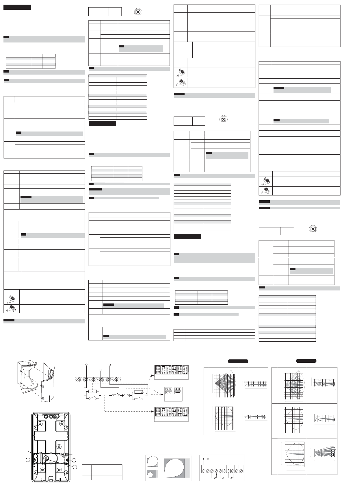
Figure 1.
Back cover - Knockouts
I ponticelli J1 e J2 permettono la selezione dei valori resistivi da assegnare
ai circuiti di Tamper e di Allarme (1K, 2.2K, 4.7K, 5.6K, 6.8K) in funzione
della centrale d’allarme utilizzata (vedere la Figura 3 in basso). Il ponticello
FAULT/AM EOL
J3 inoltre, permette la selezione di una resistenza di 12K per supervisionare
il circuito Anomalia/Anti-Mask.
Seguire lo schema di collegamento dei morsetti illustrato in Figura 3 quando
si vuole collegare il sensore ad una centrale d’allarme usando il doppio o il
triplo bilanciamento resistivo (DEOL/TEOL).
Usato per impostare la polarità dei comandi di
attivazione per gli ingressi LED e SET.
Posizionato sul lato 12V richiede come comando di attivazione una tensione
positiva. Fare riferimento alla sezione relativa il Cablaggio Morsettiera, morsetti
LED e SET.
Posizionato su 0V richiede come comando di attivazione un riferimento
negativo di alimentazione 0V. Fare riferimento alla sezione relativa il Cablaggio
Morsettiera, morsetti LED e SET.
Figure 2.
Lens Replacement
Sleeve
Cut
Corners
Back tamper
“Breakable” plate
A3
Short Pin
(Facing upwards)
Lens
che integrano le tecnologie più
ed ha le resistenze di fine linea
Figure 3.
Schematic of EOL Resistors Tamper / Alarm EOL Jumpers
+12- ALARM TAMPER FAULT/AM LED SET
Range Adjustment
Bolt Thread
A1
A2
Regolazione Portata MW (vedere Figura 4)
1 Regolazione Alta
2 Regolazione Bassa
3 Regolazione corretta
LED Stato Descrizione
LED Stato Descrizione
Giallo
Verde
Rosso
Tutti i LED Lampeggianti
Nota: L’indicazione di Mascheramento e/o Anomalia persiste fino a quando la causa non viene
rimossa.
Specifiche Tecniche
Elettriche
Assorbimento di corrente 16.8mA a 12V - (Nominale)
Alimentazione richiesta
Contatti di allarme
Contatti Tamper
Contatti FAULT/AM
Ambientali
Immunità RF Secondo EN50130-4
Temp. funzionamento da -10ºC a 55ºC
Temp. stoccaggio da -20ºC a 60ºC
Ottica
Filtro Protezione contro le luci bianche
Fisiche
Dimensioni 127.6 mm x 64.2 mm x 46.6 mm
Peso 120 gr.
ESPAÑOL
Los detectores RK815DTG3/RK825DTG3 son la última palabra en detectores para instalaciones
profesionales, incorporando las Tecnologías Anti-Enmascaramiento y Anti-Cloak™ (ACT™),
adhiriéndose a las nuevas directrices respetuosas con el medioambiente.
Los detectores iWISE 815DTG3/825DTG3 están disponibles en modelos de 15m y 25m, e incluyen
resistencias incorporadas de fin de línea (EOL) para simplificar la instalación.
Instalación / Mantenimiento
1. Montaje - El iWISE 815DTG3/825DTG3 puede montarse en una superficie plana o en un rincón
de pared (montaje en rincón).
•
Usando una herramienta apropiada, abra los siguientes agujeros pre-marcados en la base del
detector (ver Figura 1).
Nota: Si se va a usar un tamper posterior, es obligatorio atornillar la placa posterior del tamper a
la pared (o al rincón de la pared).
2. Para selecccionar la posición correcta de ajuste vertical para lentes gran angular utilice la escala
en el lado izquierdo del PCB, según se indica:
Altura de montaje y posición de la escala según el tamaño de la habitación:
Altura de Montaje L - LONG S - SHORT
Para RK815DTG3
2.1m-2.7m (6'11"-8’10") 15m (50’) 6m (20’)
Para RK825DTG3
1.8m-2.0m (5'11"-6’7") 25m (82’) 8m (26’)
Nota: Para instalaciones de Pasillo, seleccione la posición “LONG” e instale a 2.5m/8’2” de altura.
3. Configure los puentes (véase la sección Configuración de Puentes).
IMPORTANTE: En la superficie del Microondas encontrará un punto de color, que representa el canal
Microondas. Al instalar dos detectores en localizaciones cercanas, se recomienda que estos puntos
(canales) no sean del mismo color. Ejemplo: Deberían evitarse dos Rojos.
Nota: Reinicie el detector después de que se haga un cambio en las configuraciones.
4. Coloque de nuevo la tapa delantera en su lugar (de modo inverso al de retirarla)
5. Realice una prueba de Movimiento (véase la sección Prueba de Movimiento).
6. Cambiando las Lentes (ver Figura 2).
Cableado del Terminal (ver Figura 5)
Terminal Descripción
- 12 + Entrada de 12VCC
ALARM Relé N.C.
TAMPER
FAULT/AM
(Fallo/AM)
LED
SET
**Señal de Activación-
Si se aplican 12VCC, y el puente (jumper) LED/SET INPUT está en la posición 12V
Se aplican 0V y el puente (jumper) LED/SET INPUT está en la posición 0V.
Configuración de los Puentes
Puente Función
SW1-1: LED
(Predeterm.)
SW1-2: ACT
(Predeterm.)
SW1-3: Green Line
El RK815DTG3/RK825DTG3 incluye una característica Green Line que sigue las directivas
medioambientales evitando un exceso de emisión. Esta característica deshabilita el canal MW
cuando el sistema de alarma está “DESARMADO”, eliminando así la emisión excedente de
MW mientras las instalaciones estén ocupadas.
PANEL TEOL
A Rivelatore
B Corridoio
Illuminato Rilevazione del canale PIR
Lampeggiante Anomalia del canale PIR
Illuminato Rilevazione del canale MW
Lampeggiante Anomalia del canale MW
Illuminato ALLARME
Lampeggiante
(consecutivamente)
Conmutador del Tamper N.C.
Relé Normalmente Cerrado: El relé FALLO/AM se abre en los siguientes
eventos:
• El detector está tapado (el relé de Alarma también se abre)
• Fallo en el auto test
• El voltaje de entrada es inferior a 8VCC
Control remoto del funcionamiento del LED
Cuando se aplica una ”Señal de Activación”** al terminal de entrada del
LED, se desactivan todos los LEDs.
Los LEDs se activan si no hay nada conectado (a menos que el puente
del LED esté en OFF) o se aplican 0V/12V (según la posición del Puente
LED/SETInput, 12V ó 0V)
Control remoto del Armado/Desarmado (SET/UNSET)
Armado (SET): Si se aplica una ”Señal de Activación”**, la detección de
anti-enmascaramiento se desactiva (para la configuración de Grado 2).
Desarmado (UNSET): Si no hay nada conectado o se aplican 0V/12V
(según la posición del Puente LED/SET Input, 12V ó 0V) se hablita la
detección de anti-enmascaramiento (véase también “Green Line” y
“Auto Test Remoto” en la tabla Configuración de los Puentes).
Usado para determinar el funcionamiento de los LEDs del detector.
Los LEDs están habilitados, permitiendo el control del LED a través del
ON
terminal de entrada del LED
Los LEDs están deshabilitados.
OFF
Usado para determinar si el modo ACT está habilitado o deshabilitado
ACT Habilitado
ON
Importante: No use el modo ACT™ si usted espera que haya objetos en
movimiento fuera del área protegida requerida, p.ej. un pasillo.
OFF
ACT Deshabilitado.
La característica Green Line está habilitada: Para desactivar el módulo de MW
en el periodo de “Desarmado”, los LEDs también deben deshabilitarse
remotamente mediante el terminal LED.
ON
Nota: Cuando ‘Green Line’ está activado (MW desactivado), el detector aún
se activará (sólo PIR).
MIN MAX
Anomalia / Rilevazione circuito Anti-Mask
Nota: La rilevazione del canale Anti-Mask può essere
attiva solo ad impianto “Disinserito” (Consultare la
sezione del Cablaggio morsettiera, morsetto SET).
All’alimentazione tutti i LED lampeggiano in sequenza fino
alla fine del periodo di inizializzazione (2-3 minuti).
Alla fine del periodo di inizializzazione il LED ROSSO
continuerà a lampeggiare fino alla fine della fase
di inizializzazione del canale Anti-Mask.
39.5mA a 12V - (Massimo)
da 9V- a 16V24V- 0.1A
24V- 0.1A
24V- 0.1A
- O -
J1 - ALARM EOL JUMPERS
PANEL DEOL
No 1K 2.2K 4.7K 5.6K 6.8K
Resistor
(Factory Settings)
J3 - FAULT/AM EOL JUMPERS
TAMPER
ALARM
Tamper Plate
Right corner mounting knockouts
A1
A2
Wall mounting knockout
A3
Left corner mounting knockout
SHORT
FAULT/AM
J2 - TAMPER EOL JUMPERS
No 1K 2.2K 4.7K 5.6K 6.8K
Resistor
(Factory Settings)
Figure 4.
MW range adjustment
1
2
La característica Green Line está deshabilitada: el MW está constantemente
OFF
en uso
(Predeterm.)
SW1-4: SELF
Usado para testar las tecnologías de detección.
TEST
(Auto Test)
LO (Auto Test Local): Si no hay detección de alarma en el canal PIR durante
ON
el periodo de 1 hora, el detector hará una auto prueba. Si la auto prueba local
falla, se activará el Relé FAULT/AM (FALLO/AM).
RE (Auto Test Remoto): El Auto Test Remoto se activa cuando el terminal SET
OFF
se cambia del modo SET (Armado) a UNSET (Desarmado). Si el auto test
remoto tiene éxito, se activará el Relé ALARM (Alarma) durante 5 segundos.
(Predeterm.)
En caso de fallo del auto test remoto, se activará el Relé FAULT/AM (FALLO/AM).
J1 - Alarm EOL
J2 - Tamper EOL
J3 - FAULT/AM EOL
Puentes TRIPLE
EOL (Fin de Línea)
J4 - LED/SET
INPUT
(ENTRADA
LED/SET)
Los puentes J1 y J2 permiten la selección de la resistencia del Tamper y
de la Alarma (1K, 2.2K, 4.7K, 5.6K, 6.8K) según el panel de control
(véase Figura 3 abajo). El puente J3 permite la selección de 12K para
Fallo/Anti-Enmascaramiento.
Siga el diagrama de conexión del bloque de terminales de la Figura 3
cuando conecte el detector a una Zona de Doble/Triple Fin-de-Línea
(DEOL/TEOL)
Usado para determinar la polaridad de la entrada externa.
Véase la sección Cableado del Terminal, Terminales LED y SET
Véase la sección Cableado del Terminal, Terminales LED y SET
Prueba de Movimiento
Importante:
Después de dar alimentación al detector, quite la pegatina de advertencia de la lente y cierre
la tapa dentro de los 2 minutos siguientes, pues después de este periodo comenzará la inicialización del AM.
1. Dos minutos después de la puesta en marcha (periodo de calentamiento), haga la prueba de
movimiento al detector en toda el área protegida para verificar el correcto funcionamiento de la
unidad (véase Figura 6).
2. El rango de MW puede ajustarse mediante el potenciómetro situado en el PCB (placa de circuito
impreso). Es importante ajustar el potenciómetro a la configuración más baja posible que aún
pueda proporcionar suficiente cobertura al límite interno del área protegida.
Ajuste del Rango de MW (véase Figura 4)
1 Energía excesiva
2 Energía baja
3 Ajuste correcto
Visualización de los LEDs
LED Estado Descripción
Amarillo
Verde Encendido Detección MW
Rojo
Todos los LEDs
Notas: Las indicaciones de AM y Problema continúan hasta que se elimina el enmascaramiento
o se soluciona el problema.
Especificaciones Técnicas
Eléctricas
Consumo de corriente 16.8mA a 12VCC (Típico)
Requisitos de voltaje 9 -16VCC
Contactos de Alarma 24VCC, 0.1A
Contactos de Tamper 24VCC, 0.1A
Contactos FALLO/AM 24VCC, 0.1A
Ambientales
Inmunidad a RF Según EN50130-4
Temperatura de funcionamiento -10ºC a 55ºC (14F a 131F)
Temperatura de almacenamiento -20ºC a 60ºC (-4F a 140F)
Óptica
Filtrado Protección contra luz blanca
Físicas
Tamaño 127.6 x 64.2 x 46.6 mm
Peso 120 gr. (4.2 oz.)
A Detector
B Pasillo
Encendido Detección PIR
Parpadeando Problema en el canal PIR
Parpadeando Problema en el canal MW
Encendido ALARMA
Parpadeando Fallo / Detección Anti-Enmascaramiento
Parpadeando
(sucesivamente)
MIN MAX
Notas: La detección Anti-Enmascaramiento sólo
funciona en modo “Desarmado” (Unset). (Véase la
sección Cableado del Terminal, terminal SET).
Al poner en marcha, los LEDs parpadearán
consecutivamente hasta el final del periodo de
calentamiento (2-3 minutos). Al final del periodo de
calentamiento, el LED ROJO continuará parpadeando
hasta el final de la iniciación del AM.
39.5mA a 12VCC (Máx.)
(5 x 2.5 x 1.84 pul)
PORTUGUÊS
Os detectores RK815DTG3/RK825DTG3 são a última palavra em detectores de movimento para
para instalações profissionais, incorporando a tecnologia Anti-máscara e Anti-Cloak™ (ACT™Tecnologia Anti-camuflagem), aderindo às novas diretrizes amistosas do meio-ambiente.
Os detectores RK815DTG3/RK825DTG3 estão disponíveis em modelos de 15m e 25m, e incluem
resistências embutidas de fim-de-linha (EOL) para simplificar a instalação.
Nota: Todos os detectores da RISCO Group que possuem o sistema de anti-máscara através de
Infravermelho Ativo, possuem uma proteção contra luz branca diretamente em cima do sensor
piroelétrico, isso não é uma proteção para transporte. Não retire a proteção contra luz branca,
pois isso além de não melhorar o desempenho, torna o detector passivo de disparos falsos gerados
por rajadas de luz.
Instalação / Manutenção
1. Montagem - O RK815DTG3/RK825DTG3 pode ser montado numa superfície plana ou num
canto da parede (montagem de canto).
• Usando uma ferramenta apropriada, abra os seguintes furos pré-marcados na base do detector
(ver Figura 1).
Nota: Se um tamper de parede precisa ser usado, é obrigatório parafusar a parte plástica traseira na
parede (ou ao canto da parede).
2. Para usar a posição correta de ajuste vertical para lentes de ângulo aberto, use a escala localizada
no lado esquerdo inferior do PCB, como segue:
Altura de montagem e posição da escala baseada no tamanho do local:
Altura de Montagem L - LONGA C - CURTA
Para RK815DTG3
2.1m-2.7m (6'11"-8’10") 15m (50’) 6m (20’)
Para RK825DTG3
1.8m-2.0m (5'11"-6’7") 25m (82’) 8m (26’)
Nota: Para instalações de Corredor, selecione a posição “LONGA” e instale a 2.5m/8’2” de altura.
3. Configure os jumpers (ver a seção Configuração de Jumpers).
Nota: Reajuste o detector depois de cada modificação feita nas configurações.
4. Recoloque a tampa dianteira em seu lugar (na seqüência contrária à da remoção)
5. Realize uma prova de Caminhada (ver a seção Prova de Caminhada).
6. Troca de Lentes (ver. Figura 2).
Terminais de Fiação (ver. Figura 5)
Terminal Descrição
- 12 +
ALARME
TAMPER
Short
No
12K
Resistor
(Factory Settings)
A
3
(ver Figura 1).
Entrada de 12VDC
Relé N.F.
Chave do tamper N.F.
Figure 6.
RK815DTG3/RK825DTG3 Lense and microwave Range
Figure 5.
Terminal Wiring
12VDC
+ 12 - ALARM TAMPER FAULT/AMLED SET
B
TOP VIEW SIDE VIEW
Feet
40
12
10
30
8
20
6
A)
4
10
e
2
d
ielgn
0
0
2
W
10
4
20
6
521LR V(
8
30
10
40
12
Meters
0 2 4 6 8 1012141618202224
0102030 82
Feet
Feet
40
12
10
30
8
)
r
20
6
o
4
d
10
i
2
r
roC(V71L
0
0
2
10
4
20
6
8
30
10
40
12
R
Meters
0 2 4 6 810121416182022
0102030 82
Feet
RK825DTG3
83°
Meters
25
Feet
Meters
Feet
23
Feet
4
10
2
0
0
0 2 4 6 8 10121416 1820222425
0102030 82
Feet
4
10
2
0
0
0 2 4 6 8 10 121416 18 202223
0102030 82
Relé Normalmente Fechado: O relé FALHA/AM se abre nos seguintes eventos:
FALHA/AM
• O detector é Mascarado (O relé do Alarme também se abre)
• Falha no auto teste
• A voltagem de entrada é inferior a 8VDC
Controle remoto da operação do LED
LED
Quando um “Sinal de Acionamento”** é aplicado ao terminal de entrada
do LED, todos os LEDs serão desativados .
Os LEDs são ativados se nada estiver conectado (a menos que o jumper
do LED esteja em OFF) ou 0V/12V for aplicado (segundo a posição do
Jumper de Entrada do LED, 12V ou 0V)
SET
Controle remoto do SET/UNSET
SET: Se um ”Sinal de Acionamento”** é aplicado, a detecção anti-máscara é
desativada (para a configuração de Grade 2).
UNSET: Se nada é conectado ou 0V/12V é aplicado (segundo a posição
do Jumper de Entrada do LED/SET, 12V ou 0V) a detecção anti-máscara
é habilitada (ver também “Green Line” e “Auto Teste Remoto” na
tabela Configurações do Jumper).
**Sinal de Acionamento-
Se 12VDC é aplicado, e o Jumper de Entrada do LED/SET está na posição 12V
oV é aplicado e o Jumper de Entrada do LED/SET está na posição 12V
Configuração dos Jumpers
Jumper Função
SW1-1: LED
Usado para determinar a operação dos LEDs do detector.
LEDs estão habilitados, permitindo o controle do LED através do Terminal de
ON
Entrada do LED
(Predeterm.)
OFF
LEDs estão desativados.
SW1-2: ACT
Usado para determinar se o modo ACT está habilitado ou desativado.
ACT Habilitado
ON
Importante: Não use o modo ACT™ se pensa que possam existir
objetos que se movam fora da área protegida requerida, um corredor
por exemplo.
OFF
ACT Desativado.
(Predeterm.)
SW1-3: Green Line
O RK815DTG3/RK825DTG3 inclui uma característica Green Line que segue as diretrizes de
proteção ao meio ambiente, evitando a emissão de energia em excesso.
Esta característica desativa o canal de Microondas quando o sistema de alarme está “Desarmado”,
eliminando assim a emissão de excedentes de Microondas enquanto o local estiver ocupado.
A característica Green Line está habilitada: Para desativar o módulo
ON
de Microondas quando os LED’s forem desativados remotamente.
NOTA: Quando ‘Green Line’ é ativado (Microondas Desligado), o
detector ainda estará funcionando (apenas Infravermelhor Passivo).
A característica Green Line está desativada: o Microondas está
OFF
constantemente em uso
(Predeterm.)
SW1-4: Auto
Usado para testar as tecnologias de detecção.
Teste
LO (Auto Teste Local): Se não há detecção de alarme no canal Infravermelho
ON
Passivo durante o período de 1 (uma) hora, o detector fará um auto teste. Se
o auto teste local falhar, o Relé FALHA/AM será ativado.
RE (Auto Teste Remoto): O Auto Teste Remoto é ativado quando o
terminal SET é passado do modo SET a UNSET. No caso de o auto
OFF
teste ter sido bem sucedido, o Relé Alarme será ativado por 5 segundos.
(Predeterm.)
Em caso de falha do auto teste remoto, o Relé FALHA/AM será ativado.
J1 - Alarm EOL
J2 - Tamper EOL
J3 Jumpers TRIPLOS
EOL
J4 DO LED/SET
Os jumpers J1 e J2 permitem a seleção da resistência do Tamper
e do Alarme (1K, 2.2K, 4.7K, 5.6K, 6.8K) de acordo com o painel
de controle (ver Figura 3 abaixo). O jumper J3 permite a seleção
FAULT/AM EOL
de 12K para Falha/Anti-Camuflagem.
Siga o diagrama de conexão do bloco de terminais na Figura 3,
ao conectar o detector a uma Zona de Duplo/Triplo Fim-de-Linha
(DEOL/TEOL)
ENTRADA
Usado para determinar a polaridade da entrada externa.
- OU -
Ver a seção Terminais de Fiação, terminais LED e SET
Ver a seção Terminais de Fiação, terminais LED e SET
Prova de Movimento
Importante: Após a energização do detector, feche a tampa dentro de 2 minutos, já que após este
tempo o AM (Anti Mascaramento) será inicializado.
Importante: As distâncias podem variar de acordo com as condições térmicas ambientais.
1. Dois minutos depois de ativar (período de aquecimento), caminhe para testar o Detector através
de toda a área protegida para verificar a correta operação da unidade (ver Figura 6).
2. O alcance de Microondas deve ser ajustado usando-se o potenciômetro, que está localizado no
PCB. É importante colocar o potenciômetro na configuração mais baixa possível que ainda possa
proporcionar suficiente cobertura para toda a área protegida.
Ajuste do Alcance do Microondas (ver Figura 4)
1 Energia em excesso
2 Energia fraca
3 Ajuste correto
Visualização dos LEDs
LED Estado Descrição
Amarelo
Verde
LED Estado Descrição
Vermelho
Todos os LEDs
Notas: As indicações de AM e Problema continuam até que o mascaramento seja removido ou
o problema solucionado.
Especificações Técnicas
Elétricas
Consumo de Corrente
Requisitos de voltagem 9 -16VDC
Contatos de alarme 24VDC, 0.1A
Contatos de Tamper 24VDC, 0.1A
Contatos FALHA/AM 24VDC, 0.1A
Ambientais
Imunidade a RF De acordo com EN50130-4
Temperatura de operação -10C a 55C (14F a 131F)
Temperatura de armazenamento -20C a 60C (-4F a 140F)
Ótica
Filtragem Proteção contra luz branca
Físicas
Tamanho
Peso 120 gr. (4.2 oz.)
A Detector
B Corredor
Aceso Detecção de Infravermelho Passivo
Piscando Problema no canal de Infravermelho Passivo
Aceso Detecção no Microondas
Piscando Problema no canal de Microondas
Aceso ALARME
Falha / Detecção Anti-Máscara
Piscando
Notas: A detecção Anti-Máscara é ativada somente
no modo “Unset”. (ver a seção Terminais de Fiação,
terminal SET).
Piscando
Ao conectar, os LEDs piscarão consecutivamente até
(sucessivamente)
o final do período de aquecimento (2-3 minutos). Ao
final do período de aquecimento, o LED VERMELHO
continuará piscando até o final da iniciação do AM.
16.8mA a 12VDC (Típico)
39.5mA a 12VDC (Máx.)
127.6 x 64.2 x 46.6 mm
(5 x 2.5 x 1.84 pol.)
MIN MAX
RK815DTG3
TOP VIEW SIDE VIEW
Feet
)V51L
10
30
8
n
20
6
Aelg
4
edi
10
2
0
0
W
(
2
10
4
20
6
8
L
30
10
R1 VD51
Meters
02468101214
Feet
01020304050
Feet
10
30
8
20
6
)
r
4
10
2
r
rodi
0
0
C
2
(
10
4
20
6
8
30
Ro
10
Meters
02468101214
Feet
01020304050
Feet
8
30
6
20
4
rt nia)
10
2
uC
0
0
(
V
2
10
4
20
6
LR1 C51
30
8
Meters
024 681012
Feet
010203040
Feet
10
98°
0
Meters
Feet
15
Feet
10
0
Meters
Feet
15
Feet
10
0
Meters
Feet
4
2
0
0246810121415
0 10 20 30 40 50
4
2
0
0 2 4 6 8 10 12 1415
0 10 20 30 40 50
4
2
0
024 6 81012
010203040
 Loading...