

Page 1
Drain Cleaning
Machine
OPERATOR’S
MANUAL
• Français – 15
• Castellano – pág. 33
K-3800
WARNING!
Read this Operator’s Manual
carefully before using this
tool. Failure to understand
and follow the contents of this
manual may result in electrical shock, fire and/or serious
personal injury.
Page 2

K-3800 Drain Cleaning Machine
Ridge Tool Companyii
Table of Contents
Recording Form for Machine Serial Number..............................................................................................................1
General Safety Information
Work Area Safety........................................................................................................................................................2
Electrical Safety..........................................................................................................................................................2
Personal Safety ..........................................................................................................................................................2
Tool Use and Care......................................................................................................................................................3
Service........................................................................................................................................................................3
Specific Safety Information
Machine Safety...........................................................................................................................................................3
Description, Specifications and Standard Equipment
Description..................................................................................................................................................................4
Specifications..............................................................................................................................................................4
Standard Equipment...................................................................................................................................................4
Accessories ................................................................................................................................................................4
Machine Assembly
Installing Drum ...........................................................................................................................................................5
Instructions For Mounting Autofeed ...........................................................................................................................5
Machine Inspection ......................................................................................................................................................6
Machine Set Up .............................................................................................................................................................6
Operating Instructions
Using Manual Feed Machine......................................................................................................................................8
Using Autofeed Machine............................................................................................................................................8
Special Procedures
Reverse Operating Instructions................................................................................................................................10
Removing Drum .......................................................................................................................................................10
Machine Transport ...................................................................................................................................................10
Draining Water From Drum......................................................................................................................................10
Installing Replacement Cable
To Remove Damaged or Worn Cables....................................................................................................................10
To Install Replacement Cables ................................................................................................................................11
Accessories
Replacement Cables & Tools...................................................................................................................................12
Maintenance Instructions
Lubrication................................................................................................................................................................13
Autofeed Assembly ..................................................................................................................................................13
Cables......................................................................................................................................................................13
Machine Storage.........................................................................................................................................................13
Service and Repair .....................................................................................................................................................13
Troubleshooting .........................................................................................................................................................14
Wiring Diagram...........................................................................................................................................................15
Lifetime Warranty.........................................................................................................................................Back Cover
Page 3
K-3800
Drain Cleaning Machine
K-3800 Drain Cleaner
Record Serial Number below and retain product serial number which is located on nameplate.
Serial
No.
Page 4
K-3800 Drain Cleaning Machine
Ridge Tool Company2
are rated for outdoor use and reduce the risk of electrical shock.
• Use only three-wire extension cords which have
three-prong grounding plugs and three-pole receptacles which accept the tool’s plug. Use of other
extension cords will not ground the tool and increase
the risk of electrical shock.
• Use proper extension cords. (See chart.) Insufficient
conductor size will cause excessive voltage drop, loss
of power.
• Before using, test the Ground Fault Circuit Inter-
rupter (GFCI) provided with the power cord to insure it is operating correctly. GFCI reduces the risk
of electrical shock.
• Extension cords are not recommended unless
they are plugged into a Ground Fault Circuit Interrupter (GFCI) found in circuit boxes or outlet receptacles. The GFCI on the machine power cord will
not prevent electrical shock from the extension cords.
• Keep all electric connections dry and off the
ground. Do not touch plug with wet hands. Reduces
the risk of electrical shock.
Personal Safety
• Stay alert, watch what you are doing and use common sense when operating a power tool. Do not
use tool while tired or under the influence of drugs,
alcohol, or medications. A moment of inattention
while operating power tools may result in serious personal injury.
• Dress properly. Do not wear loose clothing or jew-
elry. Contain long hair. Keep your hair, clothing,
and gloves away from moving parts. Loose clothes,
jewelry, or long hair can be caught in moving parts.
• Avoid accidental starting. Be sure switch is OFF
before plugging in. Carrying tools with your finger on
the switch or plugging tools in that have the switch ON
invites accidents.
• Remove adjusting keys or switches before turning
the tool ON. A wrench or a key that is left attached to
a rotating part of the tool may result in personal injury.
General Safety Information
WARNING! Read and understand all instructions. Failure
to follow all instructions listed below may
result in electric shock, fire, and/or serious
personal injury.
SAVE THESE INSTRUCTIONS!
Work Area Safety
• Keep your work area clean and well lit. Cluttered
benches and dark areas invite accidents.
• Do not operate tools in explosive atmospheres,
such as in the presence of flammable liquids,
gases, or dust. Tools create sparks which may ignite
the dust or fumes.
• Keep bystanders, children, and visitors away
while operating a tool. Distractions can cause you to
lose control.
Electrical Safety
• Grounded tools must be plugged into an outlet,
properly installed and grounded in accordance
with all codes and ordinances. Never remove the
grounding prong or modify the plug in any way. Do
not use any adapter plugs. Check with a qualified
electrician if you are in doubt as to whether the outlet is properly grounded. If the tool should electrically
malfunction or break down, grounding provides a low resistance path to carry electricity away from the user.
• Avoid body contact with grounded surfaces such
as pipes, radiators, ranges and refrigerators. There
is an increased risk of electrical shock if your body is
grounded.
• Don’t expose electrical tools to rain or wet condi-
tions. Water entering a tool will increase the risk of
electrical shock.
• Do not abuse cord. Never use the cord to carry the
tools or pull the plug from an outlet. Keep cord
away from heat, oil, sharp edges or moving parts.
Replace damaged cords immediately. Damaged
cords increase the risk of electrical shock.
• When operating a tool outside, use an outdoor
extension cord marked “W-A” or “W”. These cords
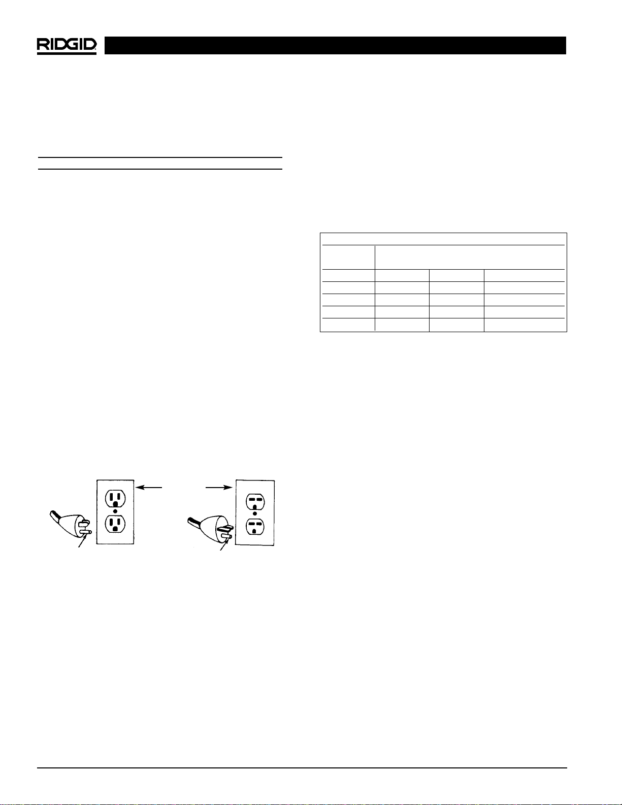
Grounding prong
Cover of
grounded
outlet box
Grounding prong
Minimum Wire Gauge for Extension Cord
Nameplate
Amps
Total Length (in feet)
0 – 25 26 – 50 51 – 100
0 – 6 18 AWG 16 AWG 16 AWG
6 – 10 18 AWG 16 AWG 14 AWG
10 – 12 16 AWG 16 AWG 14 AWG
12 – 16 14 AWG 12 AWG
NOT RECOMMENDED
Page 5

• Do not overreach. Keep proper footing and bal-
ance at all times. Proper footing and balance enables
better control of the tool in unexpected situations.
• Use safety equipment. Always wear eye protection.
Dust mask, non-skid safety shoes, hard hat, or hearing
protection must be used for appropriate conditions.
Tool Use and Care
• Use clamp or other practical way to secure and
support the workpiece to a stable platform. Holding
the work by hand or against your body is unstable and
may lead to loss of control.
• Do not force tool. Use the correct tool for your ap-
plication. The correct tool will do the job better and
safer at the rate for which it is designed.
• Do not use tool if switch does not turn it ON or
OFF. Any tool that cannot be controlled with the switch
is dangerous and must be repaired.
• Disconnect the plug from the power source before
making any adjustments, changing accessories, or
storing the tool. Such preventive safety measures re-
duce the risk of starting the tool accidentally.
• Store idle tools out of the reach of children and
other untrained persons. Tools are dangerous in
the hands of untrained users.
• Maintain tools with care. Keep cutting tools sharp
and clean. Properly maintained tools with sharp cutting
edges are less likely to bind and are easier to control.
• Check for misalignment or binding of moving
parts, breakage of parts, and any other condition
that may affect the tools operation. If damaged,
have the tool serviced before using. Many accidents
are caused by poorly maintained tools.
• Use only accessories that are recommended by
the manufacturer for your model. Accessories that
may be suitable for one tool may become hazardous
when used on another tool.
• Keep handles dry and clean; free from oil and
grease. Allows for better control of the tool.
Service
• Tool service must be performed only by qualified
repair personnel. Service or maintenance performed
by unqualified repair personnel could result in injury.
• When servicing a tool, use only identical replace-
ment parts. Follow instructions in the Maintenance
Section of this manual. Use of unauthorized parts or
failure to follow maintenance instructions may create a
risk of electrical shock or injury.
Specific Safety Information
WARNING
Read this operator’s manual carefully before using
the K-3800 Drain Cleaner. Failure to understand
and follow the contents of this manual may result in
electrical shock, fire and/or serious personal injury.
Call the Ridge Tool Company, Technical Service Department at (800) 519-3456 if you have any questions.
Drain Cleaner Safety
• Wear gloves provided with the machine. Never
grasp a rotating cable with a rag or loose fitting
cloth glove. Could become wrapped around the cable
and cause serious injury.
• Do not overstress cables. Keep two hands on the
cable for control when machine is running. Overstressing cables because of obstruction may cause
twisting, kinking or breaking of the cable and result in
serious injury.
• Position machine within two feet of inlet. Greater
distances can result in cable twisting or kinking.
• Machine is designed for one person operation.
Operator must control foot switch and cable.
• Use foot switch to operate machine while main-
taining good footing and balance. Do not operate
machine in (REV) reverse. Operating machine in
reverse can result in cable damage and is used only to
back tool out of an obstruction.
• Keep hands away from rotating drum and guide
tube. Do not reach into drum unless machine is
unplugged. Hand may be caught in the moving parts
resulting in serious injury.
• Be careful when cleaning drains where cleaning
compounds have been used. Avoid direct contact with skin and eyes. Serious burns can result
from some drain cleaning compounds.
• Do not operate machine if operator or machine is
standing in water. Will increase the risk of electrical
shock.
• Wear safety glasses and rubber soled, non-slip
shoes. Use of this safety equipment may prevent serious injury.
• Only use the K-3800 to clean drain lines up to 4″ in
diameter. Follow instructions on the use of the
machine. Other uses or modifying the drain cleaner for
other applications may increase the risk of injury.
Ridge Tool Company 3
K-3800 Drain Cleaning Machine
Page 6

Description, Specifications
And Standard Equipment
Description
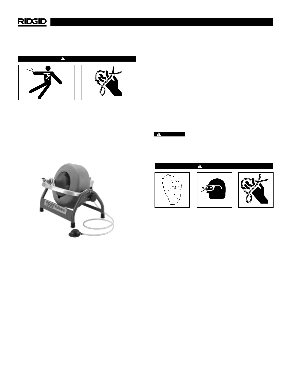
The RIDGID K-3800 Drain Cleaning Machine will clean
drain lines up to 4″ in diameter and 100 feet in length.
Drum provided with the machine holds up to 100 feet of
3
/8″ cable or 90 feet of 1/2″ cable. An optional sink drum
holds 50 feet of 5/16″ cable. Both drums include an innerdrum to guard against cable flip-over. Designed to clean
sink lines, floor drains and roof vents.
The drum is driven by a 1/10HP universal series motor that
has a grounded electrical system. An integral Ground
Fault Interrupter (GFCI) is built into the line cord and a
pneumatic foot actuator provides ON/OFF control of the
motor. When the cable hits a blockage, the motor gears
down automatically to provide more power and greater operator control.
The cable is manually fed in and out of the drain. An
optional autofeed is available that will advance or retract
the cable. Drum tilt-adjusts to provide proper cable feed
angle. The cable has a quick change coupling system for
connecting tools. The drum separates from the motor
frame for two-hand transport.
Specifications
Line Capacity...............Depends on choice of cable.
Refer to the following chart
for recommendations.
Drum Capacity
Standard Cable Drum....100′ of
3
/8″ Cable
90′ of 1/2″ Cable
Sink Drum......................50′ of 5/16″ Cable
Motor
Type ..............................115V/50-60 Hz, Reversible,
Universal AC Motor. 220-240V
Available Upon Request
Rating............................1/10HP
Amps.............................2
Weight (machine only) ...35 lbs. (15.9 kgs)
Length ...........................19″ (48 cm)
Height............................17″ (43 cm)
Width.............................14″ (36 cm)
Standard Equipment
K-3800 w/C-31 Cable, Cat. No. 53112 includes:
• K-3800 Machine
• C-31, 3/8″ x 50′′ Inner Core Cable
• T-202 Bulb Auger
• T-205 “C” Cutter 13/8″
• T-211 Spade Cutter
• A-13 Pin Key
• Pair Gloves
K-3800 w/C-32, Cat. No. 53117 includes:
• K-3800 Machine
• C-32, 3/8″ x 75′ Inner-Core Cable
• T-202 Bulb Auger
• T-205 “C” Cutter
• T-211 Spade Cutter
• A-13 Pin Key
• Pair Gloves
K-3800 w/C-45, Cat. No. 53122 includes:
• K-3800 Machine
• C-45, 1/2″ x 75′ Inner-Core Cable
• T-102 Funnel Auger
• T-142 Blade Cutter
• T-107 Spade Cutter
• A-12 Pin Key
• Pair Gloves
K-3800 w/C-46, Cat. No. 53127 includes:
• K-3800 Machine
• C-46, 1/2″ x 90′ Inner-Core Cable
• T-102 Funnel Auger
• T-142 Blade Cutter
• T-107 Spade Cutter
• A-12 Pin Key
• Pair Gloves
Ridge Tool Company4
K-3800 Drain Cleaning Machine
Line Size Distance
Cable Size in. mm ft. M
1
/4″ Cable
3
/4- 11/
4
19 - 32 35 10.6
5
/16″ Cable
3
/4- 11/
2
19 - 38 50 15.2
3
/8″ Cable 11/2- 3 38 - 75 100 30.0
1
/2″ Cable 2 - 4 50 - 100 90 27.0
Recommended Line Size and Distance
Catalog Model
No. No. Description
55002 A-380 Std Drum for
3
/8″, 1/2″ Cable
55007 A-381 Sink Drum for
5
/16″, 1/4″ Cable
41937 — Pair of Gloves
59230 A-13 Pin Key for
3
/8″ Cable
59225 A-12 Pin Key for
1
/2″ Cable
55017 — Transport Cart
55012 A-381-A Sink Drum w/25′ x
5
/16″ Inner
Core Cable
60087 — K3800 Power Feed
Accessories
Page 7
K-3800 Drain Cleaning Machine
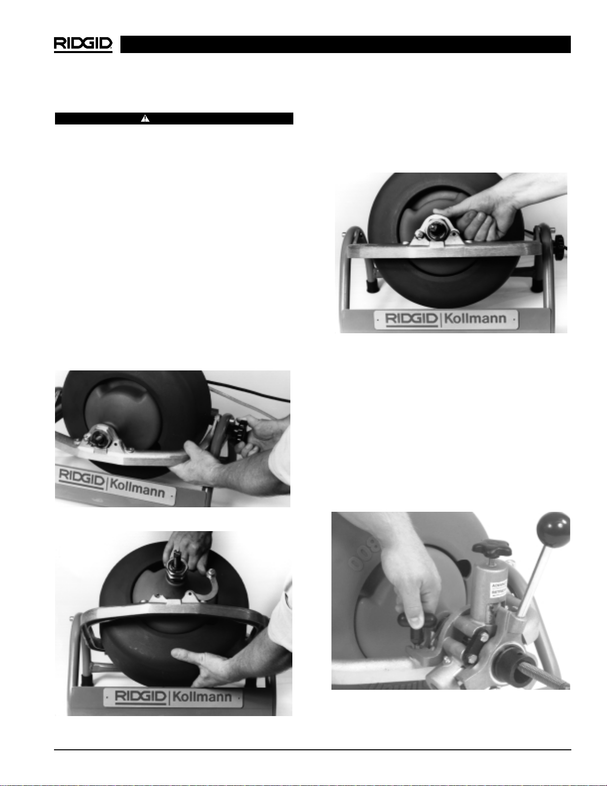
5. Close bracket over bearing assembly, push down
on bracket until push pin clicks into locked position in
yoke (Figure 3).
NOTE! If bracket does not align with groove in bearing
assembly, drive bracket is not engaged. Rotate
drum for proper engagement.
Figure 3 – Locking Front Bracket
Instructions For Mounting Autofeed
(Optional Accessory)
1. Screw handle into the autofeed.
NOTE! The autofeed comes from the factory set-up to
run both 1/2″and 3/8″ cable. No addition or removal of spacers is necessary.
2. Turn feed knob up to allow cable to pass through the
autofeed.
3. Attach the autofeed onto the front frame of the K-3800
using the two T-shaped mounting knobs (Figure 4).
Figure 4 – Mounting the Autofeed Onto the Frame
Machine Assembly
WARNING
To prevent serious injury, proper assembly of the
Drain Cleaner is required. The following procedures
should be followed:
To Install Drum
1. Loosen adjusting knob and pivot yoke assembly to a
slight angle (15 degrees) above horizontal, then
retighten knob (Figure 1).
2. Pull locking pin to release nose bracket and swing
bracket open.
3. Grasp drum at hand-hold and steady it with your
free hand. Align drum drive shaft with mounting bore
on gearbox. Then slide shaft home. Bearing assembly (on front of drum) should rest flat on its mount on
yoke (Figure 2).
4. Slowly rotate drum until drive shaft engages with
drive lug on gearbox. Drum should drop back slightly
as drive engages.
Figure 1 – Pivoting Yoke Assembly
Figure 2 – Aligning Drum and Gearbox Bore
Ridge Tool Company 5
Page 8
K-3800 Drain Cleaning Machine
Ridge Tool Company6
Machine Inspection
WARNING
To prevent serious injury, inspect your Drain Cleaning Machine. The following inspection procedures
should be performed before each use.
1. Make sure the Drain Cleaning Machine is unplugged
and the directional switch is set to the OFF position
(Figure 5).
2. Make sure the foot switch is present and attached to
the Drain Cleaning Machine (Figure 5). Do not operate the machine without a foot switch.
Figure 5 – K-3800 Drum Machine
3. Inspect the power cord, Ground Fault Circuit Interrupter (GFCI) and plug for damage. If the plug has
been modified, is missing the grounding prong or if the
cord is damaged, do not use the Drain Cleaning
Machine until the cord has been replaced.
4. Inspect the Drain Cleaning Machine for any broken,
missing, misaligned or binding parts as well as any
other conditions which may affect the safe and normal
operation of the machine. If any of these conditions
are present, do not use the Drain Cleaning Machine
until any problem has been repaired.
5. Lubricate the Drain Cleaning Machine, if necessary,
according to the Maintenance Instructions.
6. Use tools and accessories that are designed for your
drain cleaner and meet the needs of your application.
The correct tools and accessories allow you to do the
job successfully and safely. Accessories suitable for
use with other equipment may be hazardous when
used with this drain cleaner.
7. Clean any oil, grease or dirt from all equipment handles and controls. This reduces the risk of injury due
to a tool or control slipping from your grip.
8. Inspect the cutting edges of your tools. If necessary,
have them sharpened or replaced prior to using the
Drain Cleaning Machine. Dull or damaged cutting
tools can lead to binding and cable breakage.
9. Inspect cables and couplings for wear and damage.
Cables should be replaced when they become
severely worn or corroded. A worn cable can be
identified when the outside coils become flat.
Worn or damaged cables can break caus-
ing serious injury.
Machine Set-Up
WARNING
To prevent serious injury, proper set-up of the machine and work area is required. The following
procedures should be followed to set-up the machine:
1. Check work area for:
• Adequate lighting
• Grounded electrical outlet
• Clear path to the electrical outlet that does not
contain any sources of heat or oil, sharp edges or
moving parts that may damage electrical cord.
• Dry place for machine and operator. Do not place
the machine in water.
• Flammable liquids, vapors or dust that may ignite.
2. Position the Drain Cleaning Machine within 2′ of
sewer inlet. Greater distance can result in cable twisting or kinking.
3. Position the air foot switch pedal for easy operator accessibility. Machine is designed for one person
operation.
4. Make sure FOR/OFF/REV switch is in the OFF position.
5. Adjust drum and pivot yoke assembly to a convenient
position above the sewer inlet.
WARNING
Page 9
K-3800 Drain Cleaning Machine
Ridge Tool Company 7
Operating Instructions
WARNING
Wear gloves provided with machine. Never grasp
a rotating cable with a rag or loose fitting cloth
glove that may become wrapped around the cable,
causing serious injury.
Always wear eye protection to protect your eyes
against dirt and other foreign objects. Wear rubber
soled, non-slip shoes.
Be very careful when cleaning drains where cleaning compounds have been used. Wear gloves when
handling cable and avoid direct contact to the
skin and especially the eyes and facial area as serious burns can result.
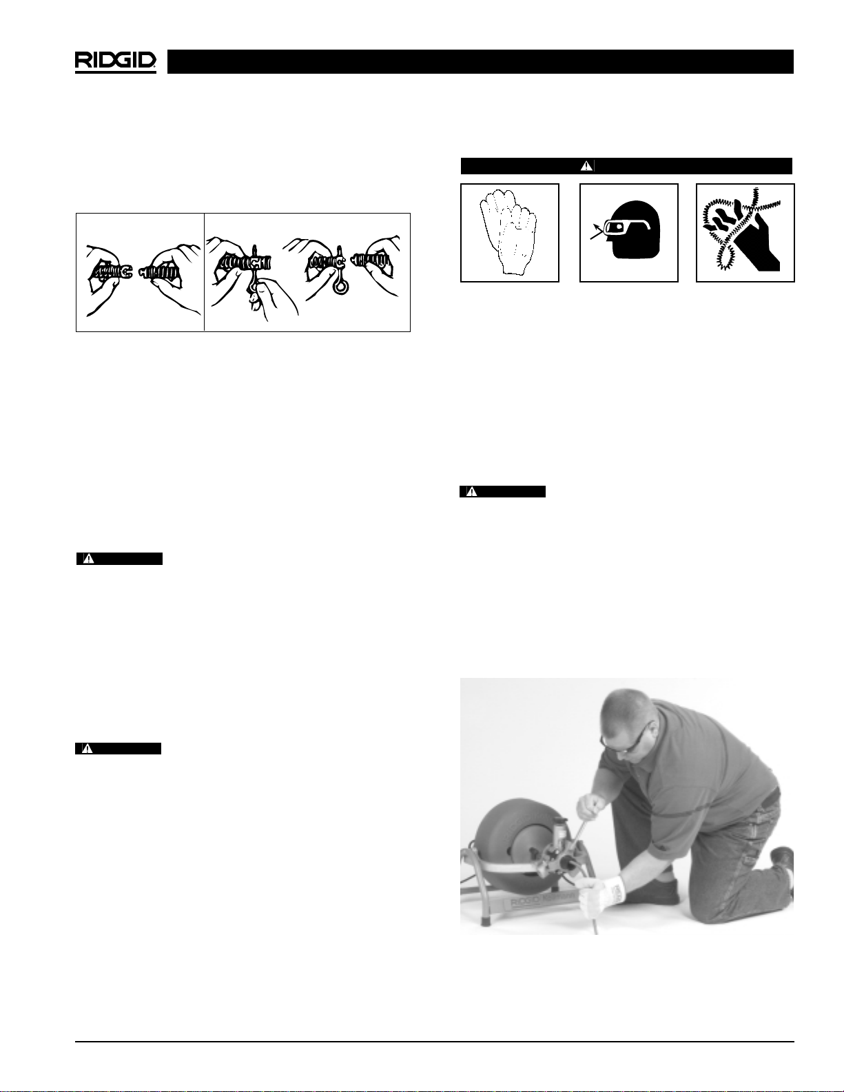
Always assume the correct operating posture in order to maintain proper balance (Figure 7). Should
an unexpected situation arise, this posture provides you
with the opportunity to safely keep control of the machine and cable.
• Be sure you can quickly remove your foot from the
foot switch.
• Hand must be on the cable to control its twisting action when it hits an obstruction.
• Keep hands away from rotating drum. Do not reach
into drum unless machine is unplugged.
Figure 7 – Proper Operating Position
6. Select and install the proper tool to the end of the
cable. The T-Slot Coupler allows the tool to be
snapped into the cable coupler (Figure 6). To re-
move tool, use the pin key to depress the plunger and
slide the coupling apart.
Figure 6 – Coupling and Uncoupling Tools
NOTE! Proper Tool Selection
A good rule of thumb is to use a tool at least 1″
smaller than the line to be cleaned. The style of the
tool is determined by the nature of the job and is
left up to the operator.
7. Plug the Drain Cleaning Machine into the electrical
outlet, making sure to position the power cord along
the clear path selected earlier. If the power cord
does not reach the outlet, use an extension cord in
good condition.
To avoid electric shock and electrical
fires, never use an extension cord that is damaged or
does not meet the following requirements:
• The cord has a three-prong plug similar to shown in
Electrical Safety section.
• The cord is rated as “W” or “W-A” if being used out-
doors.
• The cord has sufficient wire thickness (16 AWG - 100′).
If the wire thickness is too small, the cord may overheat,
melting the cord’s insulation or causing nearby objects
to ignite.
To reduce risk of electrical shock, keep all
electrical connections dry and off the ground. Do not
touch plug with wet hands. Test the Ground Fault Circuit
Interrupter (GFCI) provided with the electric cord to insure
it is operating correctly. When test button is pushed in, the
indicator light should go off. Reactivate by pushing the
reset button in. If indicator light goes on, the machine is
ready to use. If the GFCI does not function correctly, do
not use the machine.
WARNING
WARNING
WARNING
To Couple Cable
and Tools
Snap Together Insert Pin Slide Apart
To Uncouple Cable and Tools
Page 10

K-3800 Drain Cleaning Machine
Ridge Tool Company8
Using Manual Feed Machines
1. Pull sufficient cable out of the drum to start tool and
cable into the sewer inlet. Push cable into inlet as far
as it will go.
2. Move FOR/OFF/REV switch into FOR (forward) position. Grasp cable with two gloved hands and pull
approximately 1 foot of additional cable out of machine, building a slight loop of cable between machine
and sewer inlet (Figure 7).
Before starting machine, both operator’s
gloved hands must be on the cable.
3. While depressing foot switch to start machine, use
both gloved hands to grasp and push cable into
sewer inlet. Rotating cable will slowly work its way into
line as operator applies downward pressure with
gloved hands on cable loop.
4. Continue to feed the cable into the line until resistance
or obstruction is encountered. This will become apparent to operator as the motor will “lug” down and/or
the cable will have a tendency to twist sideways in operator’s hands.
5. If cable loads down in the obstruction, relieve load by
pulling back on cable with short, quick jerks to free
cutter (the drum speed will increase). Slowly advance cable back into the obstruction. Repeat this
process until the obstruction is clear. Remember,
make sure the cutter is rotating at all times and never
force the cable.
WARNING
Do not allow tension to build up in the cable. This will
happen if the cutting tool hits a snag and stops turning, but
the motor and its drum continue to rotate. Torque builds
until the cable suddenly twists, potentially wrapping around
your hand or arm. This can happen quickly and without
warning, so proceed slowly and carefully as you feed the
cable into the drain. If tool gets hung up in an obstruction,
refer to Reverse Operating Instructions in the “Special
Procedures” section.
6. Once obstruction is cleared, it is recommended to
flush debris from line with running water. Repeat
Step 5 several times if necessary for a thorough
cleaning job and then work cable through additional
stoppages as required.
7. To retrieve cable from sewer line, pull one to two
feet of cable from sewer while continuing to run machine in forward rotation. This excess cable should
then be manually pushed back into machine. This pull
and push procedure should be continued until it is apparent that tool is just inside sewer inlet.
Never retract tool from sewer inlet while
cable is rotating. Tool can whip causing serious injury.
8. Release foot actuator and allow machine to come to
a complete stop.
NOTE! It is recommended that a continuous flush of
water be used to clean the cable and tool as
they are retrieved.
9. Turn FOR/OFF/REV Switch to OFF position and re-
move cord from power source.
10. Pull remaining cable and tool from sewer and hand
feed cable back into machine.
Using Autofeed Machines
1. Manually pull sufficient cable out of the drum to start
tool and cable into the sewer inlet. Push cable into
inlet as far as it will go.
2. Turn feed knob down until front bearing makes contact with the cable.
3. Move FOR/OFF/REV switch into FOR (forward) position. Do not step on the air foot switch pedal at
this time.
4. Loosely grasp cable with gloved hand and place
right hand on the feed lever. Feed lever should be in
the neutral position (vertical or 12 o’clock). Exert
sufficient downward pressure on cable to maintain
control while depressing foot actuator to start drum
rotation. Do not force the cable. Allow it to feed itself
into the drain.
5. Move the feeder lever in the opposite direction of the
rotating drum to advance the cable (Figure 8). The
rate at which the cable is fed (0-20 feet per minute)
into the sewer is controlled by the position of the feed
lever away from neutral (vertical) position. The farther
from vertical, the faster the feed rate. Always keep
one hand on the cable to feel tension.
Before starting machine, operator’s gloved
hands must be on the cable.
Always keep hand on the cable to feel ten-
sion.
WARNING
WARNING
WARNING
WARNING
Page 11
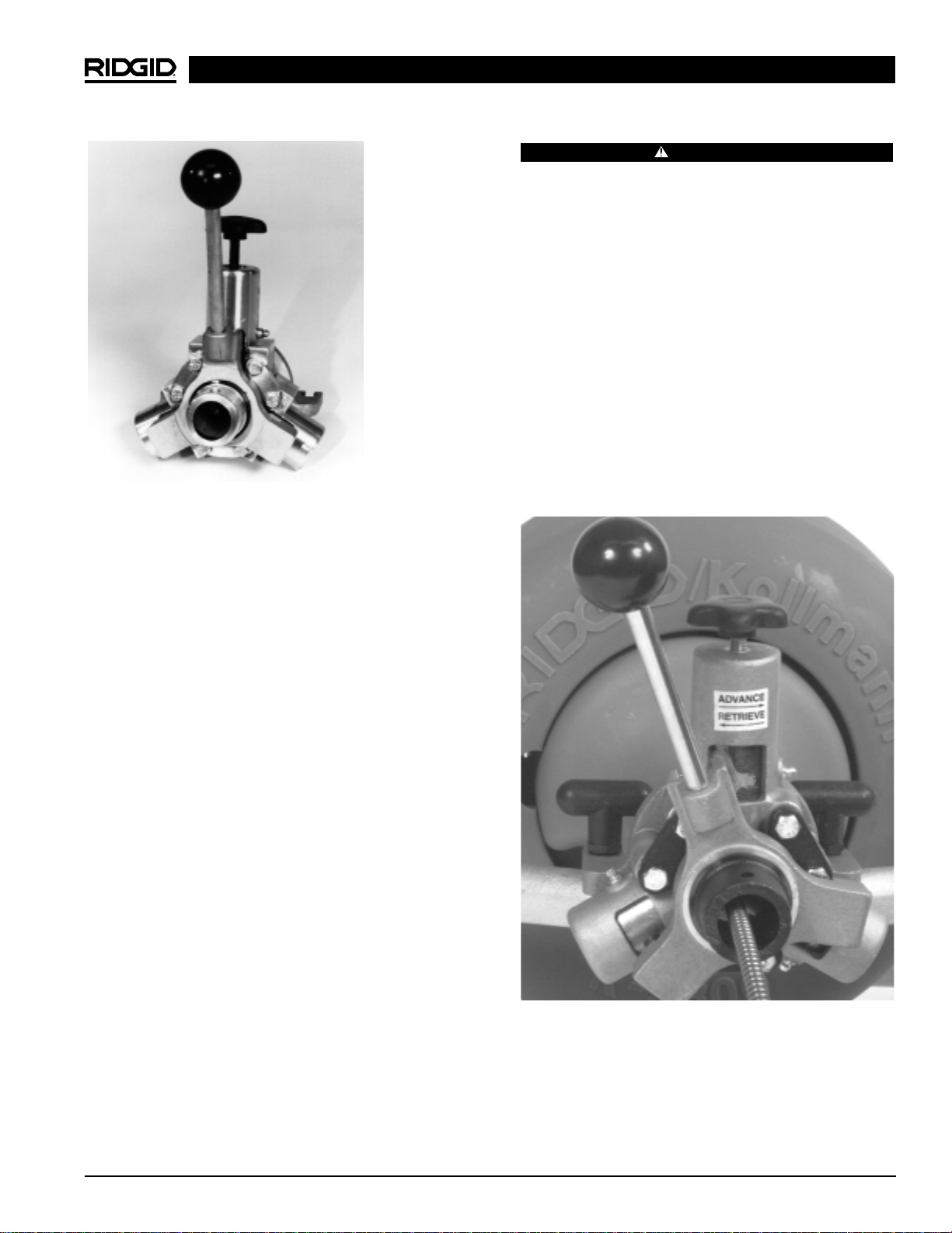
Figure 8 – Autofeed
6. Continue to feed the cable into the line until resistance
or obstruction is encountered. The condition will generally become apparent to the operator as the cable
will have a tendency to twist sideways in the operator’s hands.
NOTE! When encountering an obstruction or an elbow,
the motor/gearbox will audibly “gear down”, indicating the presence of resistance.
7. Operator should immediately respond to this condition
by moving feed lever into full reverse (same direction
of drum rotation). This should release the twist in
cable and reduce size of cable loop.
8. Once free of this obstruction and the load is relieved
from the cable, gradually feed cable forward. Remember, when using the feed mechanism the rate of
cable advance is controlled by the autofeed handle.
Allow cutter to advance slowly and work through the
obstruction. If cable shows signs of loading (generally
apparent by growing loop between machine and
drain), immediately back cutter from obstruction by reversing feed.
NOTE! At this point, progress depends upon the sharp-
ness of the tool and the nature of the obstruction.
Continued operation may require manual feed
mode until the obstruction has been cleared.
9. Manually pull back sharply on the cable to free the cutter and relieve the load on the cable. Slowly advance
cable back into the obstruction. Repeat this process
until the obstruction is clear. Remember, make sure
the cutter is rotating at all times and never force the
cable. Occasionally move power feed lever to neutral
to allow cutter to work through the obstruction.
WARNING
Do not allow tension to build up in the cable. This will happen if the cutting tool hits a snag and stops turning, but
the motor and its drum continue to rotate. Torque builds
until the cable suddenly twists, potentially wrapping
around your hand or arm. This can happen quickly and
without warning so proceed slowly and carefully as you
feed the cable into the drain. If tool gets hung up in an obstruction, refer to Reverse Operating Instructions in the
“Special Procedures” section.
10. Several passes at a thoroughly blocked drain line are
recommended. After establishing flow, increase cutter size to thoroughly clean line. Flush with strong flow
of water.
11. To retrieve cable from sewer line, move the feed
lever in same direction of drum rotation (Figure 9).
The cable should now feed itself back into machine.
The retrieval process is greatly aided by manually
pulling the cable from the drain a foot at a time as the
autofeed is used.
Figure 9 – Autofeed in Reverse Position
NOTE! It is recommended that a continuous flush of
water be used to clean cable and tool as they are
retrieved.
12. When the tool is just inside the sewer inlet, release
the air foot switch pedal and allow the machine to
come to a complete stop.
Ridge Tool Company 9
K-3800 Drain Cleaning Machine
Page 12
Never retract tool from sewer inlet while
cable is rotating. Tool can whip causing serious injury.
13. Turn FOR/OFF/REV switch to OFF position.
14. Loosen the feed knob and pull remaining cable and
tool from the sewer. Hand feed the cable into the machine.
15. Remove cord from power source.
Special Procedures
Reverse Operation
Running machine in reverse will cause premature failure
of cable. Use reverse only to free a tool caught in an
obstruction. If this should occur, immediately remove foot
from air foot switch pedal and allow machine to come to a
full and complete stop. Place FOR/OFF/REV switch to
REV (reverse) position.
Tighten screw on nose of machine so that it firmly captures cable to avoid kinks occurring inside the drum. If
machine has automatic feed, move feed knob to neutral
position. Grasp cable with gloved hands and pull while jogging air foot switch pedal. When tool is dislodged and
drum has stopped rotating, place FOR/OFF/REV switch in
FOR (forward) position, loosen set screw on nose of machine and follow normal operating procedure.
Never operate this machine in REV (reverse) for any other purpose. Operating in reverse can
damage a cable and cause serious injury.
To Remove Drum
FOR/OFF/REV switch should be OFF and
machine unplugged before removing or installing drum.
1. Pull locking pin to release bracket – swing bracket
open (Figure 10).
Figure 10 – Open Front Bracket
2. Grasp drum at hand hold and pull slightly forward to
disengage drive, then lift free of yoke.
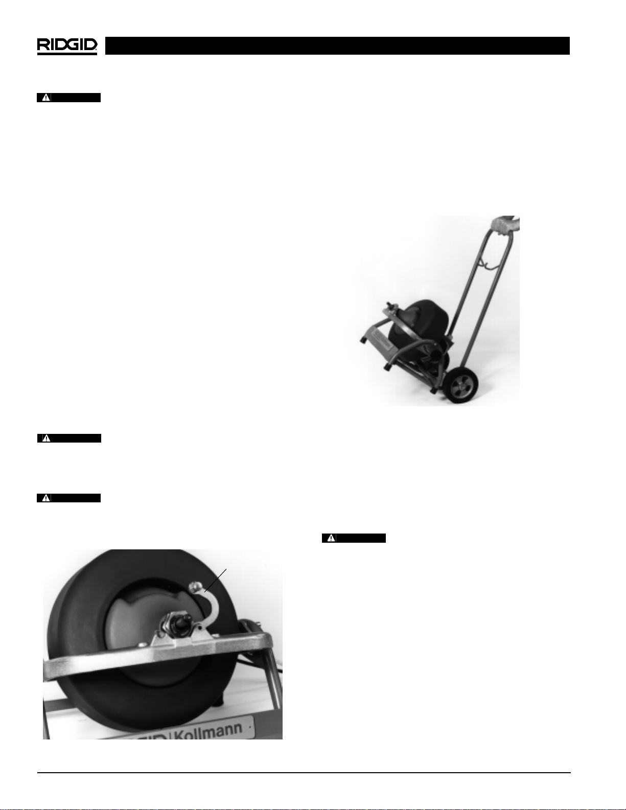
Machine Transport
The K-3800 is easier to transport with the drum removed.
Separating the drum from the frame creates balanced,
easy to carry assemblies.
An optional two-wheel cart is also available (Figure 11)
Cat. No. 55017.
Figure 11 – Optional Transport Cart
Draining Water From Drum
Rotate drum so that drain hole is at lowest point – the six
o’clock position. Remove plug and drain drum, then replace plug.
Installing Replacement Cable
FOR/OFF/REV switch should be OFF and
machine unplugged before removing or installing cable.
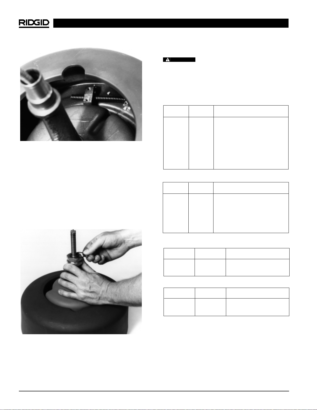
To Remove Damaged or Worn Cable
1. Remove drum from machine as outlined.
2. Pull out loose cable from drum. End of cable is fastened to back wall of drum.
3. To free cable end, loosen two bolts on drum back that
clamp the cable’s end against the back wall of the
drum (Figure 12).
4. Grasp the neck of the inner-drum and rotate it counter-clockwise to pull cable end from under bracket
(Figure 13).
5. Pull remaining length of cable from drum and discard.
Ridge Tool Company10
K-3800 Drain Cleaning Machine
WARNING
WARNING
WARNING
Bracket
WARNING
Page 13
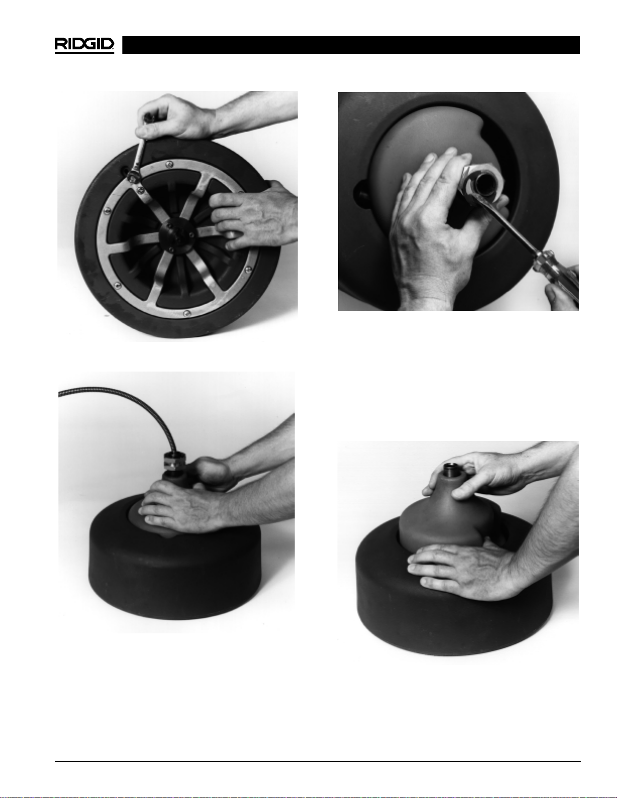
Figure 12 – Loosen Cable Bracket
Figure 13 – Removing Cable End
Figure 14 – Removing E-Clips
To Install Replacement Cable
1. Remove two E-Clips, front bearing assembly, and
inner-drum from guide tube shaft (Figure 14 and
Figure 15).
2. Insert approximately two feet of cable through the
guide tube into drum. Let cable follow natural sweep
of guide tube.
Figure 15 – Removing Inner Drum
3. Reach inside drum and grasp cable near end. Position cable end under cable bracket. Allow 2″ of
cable to protrude past clamp bracket (Figure 16).
Ridge Tool Company 11
K-3800 Drain Cleaning Machine
Page 14
K-3800 Drain Cleaning Machine
Ridge Tool Company12
Figure 16 – Position New Cable Under Bracket
NOTE! If cable will not fit under bracket, loosen the
two bolts at the drum back.
4. With cable end under bracket, retighten bolts to
clamp cable firmly against the back wall of the drum.
5. Lay drum on its back and push cable into drum.
Guide tube will evenly distribute the cable around the
drum.
6. Reassemble inner drum, front bearing and E-clips
(Figure 17).
7. Mount drum on machine as outlined previously.
Figure 17 – Reassemble Inner Drum, Front Bracket and
E-Clips
Accessories
Only the following RIDGID products have
been designed to function with the K-3800 Drain Cleaning
Machine. Other accessories suitable for use with other
tools may become hazardous when used on the K-3800.
To prevent serious injury, use only the accessories listed
below.
Catalog Model
No. No. Description
37842 C-31 50′ (15m) I.C. Cable
37847 C-32 75′ (23m) I.C. Cable
37852 C-33 100′ (30m) I.C. Cable
Catalog Model
No. No. Description
37857 C-44 50′ (15m) I.C. Cable
37862 C-45 75′ (23m) I.C. Cable
55467 C-46 90′ (27m) I.C. Cable
3/8″ Cables (10mm)
1/2″ Cable (12mm)
Catalog Model
No. No. Description
56782 C-1IC
5
/16″ x 25′ (7.6m) Inner Core
w/Bulb Auger
56787 C-2IC
5
/16″ x 25′ (7.6m) Inner Core
w/Drop Head Auger
56792 C-13IC
5
/16″ x 35′ (10.7m) w/Funnel Auger
50652 S-2
1
/4″x 25′ (7.6m) w/Funnel Auger
50657 S-3
1
/4″x 35′(10.7m) w/Funnel Auger
Sink Drum Cables
WARNING
Catalog Model
No. No. Description
55002 A-380 Std Drum for
3
/8″, 1/2″ Cable
55007 A-381 Sink Drum for
5
/16″, 1/4″ Cable
41937 — Pair of Gloves
59230 A-13 Pin Key for
3
/8″ Cable
59225 A-12 Pin Key for
1
/2″ Cable
55017 — Transport Cart
55012 A-381-A Sink Drum w/25′ x
5
/16″ Inner
Core Cable
60087 — K3800 Power Feed
Accessories
Page 15
K-3800 Drain Cleaning Machine
Autofeed Assembly
Proper cleaning and lubrication of the autofeed assembly
is advised for long, trouble-free operation. After each
use, hose out autofeed assembly with water and lubricate
with lightweight machine oil.
Cables
Cables should be thoroughly flushed with water to prevent
damaging effects of sediment and drain cleaning compounds. Periodically lubricate cables and couplings with
RIDGID Cable Rust Inhibitor.
When not in use, store cables indoors to prevent deterioration by the elements.
Cables should be replaced when they become severely
corroded or worn. A worn cable can be identified when
outside coils of cable become flat.
Machine Storage
Motor-driven equipment must be kept indoors or well covered in rainy weather. Store the machine
in a locked area that is out of reach of children and people unfamiliar with drain cleaners. This machine can
cause serious injury in the hands of untrained users.
Service and Repair
WARNING
The “Maintenance Instructions” will take care of most of
the service needs of this machine. Any problems not
addressed by this section should only be handled by an
authorized RIDGID service technician.
Tool should be taken to a RIDGID Independent Authorized Service Center or returned to the factory. All repairs made by Ridge service facilities are warranted
against defects in material and workmanship.
When servicing this machine, only identical replacement parts should be used. Failure to follow
these instructions may create a risk of electrical shock or
other serious injury.
Refer to Ridge Tool catalog for complete listing of tools
and accessories.
Maintenance Instructions
WARNING
Make sure machine is unplugged from electrical
system before making any adjustment.
Lubrication
Grease all exposed moving and rotating parts such as
guide tube assembly as required.
Ridge Tool Company 13
Catalog Model
No. No. Description
62990 T-201 Straight Auger, 5″ Long
62995 T-202 Bulb Auger, 1
1
/8″ O.D.
63000 T-203 Bulb Auger,
7
/8″ O.D.
63065 T-217 Drop Head, 4″ Long
54837 T-204 “C” Cutter - 1″
63005 T-205 “C” Cutter - 1
3
/8″
63010 T-206 Funnel Auger, 3″ Long
63015 T-207 Spiral Cutter, 1
1
/4″
63020 T-208 Spiral Cutter, 1
1
/2″
63025 T-209 Spiral Cutter, 2″
63030 T-210 Spade Cutter, 1″
63035 T-211 Spade Cutter, 1
3
/8″
63040 T-212 Spade Cutter, 1
3
/4″
63045 T-213 4-Blade Cutter, 1″
63050 T-214 4-Blade Cutter, 1
3
/8″
63055 T-215 4-Blade Cutter, 1
3
/4″
63060 T-216 Chain Knocker, 2″
49002 T-260 Tool Set:
- T-202 Bulb Auger
- T-205 “C” Cutter
- T-211 Spade Cutter
- A-13 Pin Key
Tools – Fit C-31, C-32 and C-33 Cables
Catalog Model
No. No. Description
62850 T-101 Straight Auger
62855 T-102 Funnel Auger
27642 T-125 Retrieving Auger
62865 T-104 “H” Cutter, 2
1
/2″
62870 T-105 Grease Cutter, 2
1
/2″
62875 T-106 Grease Cutter, 3
1
/2″
62880 T-107 Spade Cutter, 1
3
/4″
62930 T-112 4-Blade Cutter, 1
3
/4″
62935 T-113 4-Blade Cutter, 3″
62940 T-114 Chain Knocker
54842 T-141 Knife Blade Cutter, 1
1
/2″
54852 T-142 Knife Blade Cutter, 2
1
/2″
54992 T-270 Tool Set:
- T-102 Funnel Auger
- T-142 Knife Blade Cutter
- T-107 Grease Cutter
- A-12 Pin Key
Tools – Fits C-44, C-45, and C-46 Cables
WARNING
WARNING
Page 16
K-3800 Drain Cleaning Machine
If you have any questions regarding the service or repair
of this machine, call or write to:
Ridge Tool Company
Technical Service Department
400 Clark Street
Elyria, Ohio 44035-6001
Tel: (800) 519-3456
E-mail: TechServices@ridgid.com
For name and address of your nearest Independent
Authorized Service Center, contact the Ridge Tool Company at (800) 519-3456 or http://www.ridgid.com
Ridge Tool Company14
Cable is being forced.
Cable used is incorrect pipe diameter.
Motor switched to reverse.
Cable exposed to acid.
Cable worn out.
Hole in pedal or hose.
Hole in diaphragm switch.
Faulty reverse switch.
Damaged power cord.
Short circuit in motor.
Faulty Ground Fault Circuit Interrupter.
Do Not Force Cable! Let the cutter do the work.
Use 1/2″ cables in 3″ to 4″ lines.
Use REVERSE only if cable gets caught in pipe.
Clean and oil cables routinely.
If cable is worn, replace it.
Replace damaged component.
If no problem found with pedal or hose, replace
diaphragm switch.
Replace switch.
Replace cord set.
Take motor to authorized service center.
Replace cord set that includes a Ground Fault
Circuit Interrupter.
PROBLEM CAUSE CORRECTION
Cable kinking
or breaking.
Drum stops while pedal
is depressed. Restarts
when pedal is re-pressed.
Drum turns in one direction but not the other.
Ground fault Interrupter
trips when machine is
plugged in or when foot
pedal is depressed.
Chart 1. Troubleshooting
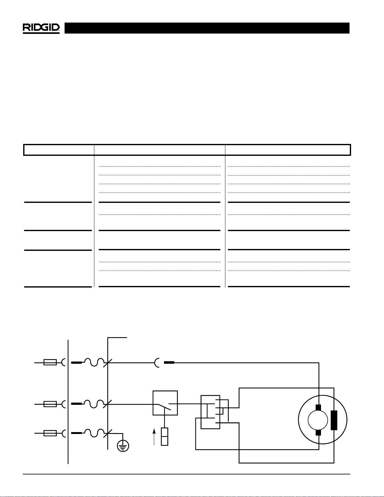
Wiring Diagram – K-3800 Drain Cleaner
N
L
PE
1.5MM
2
WH
BK
GN
Connector
Air Pressure
Switch
Switch
YE
RD
OR
M
BK
115V 60Hz
Page 17

Dégorgeoir électrique
K-3800
Dégorgeoir électrique
Inscrivez ci-dessous le numéro de série de la plaque signalétique l’appareil pour future référence.
N° de
série :
Page 18

Dégorgeoir électrique K-3800
Ridge Tool Company16
Table des matières
Fiche d’enregistrement du numéro de série de la machine...................................................................................15
Consignes générales de sécurité
Sécurité du chantier .................................................................................................................................................17
Sécurité électrique....................................................................................................................................................17
Sécurité individuelle .................................................................................................................................................17
Utilisation et entretien de l’appareil ..........................................................................................................................18
Service après-vente .................................................................................................................................................18
Consignes de sécurité particulières
Sécurité de la machine.............................................................................................................................................19
Description, spécifications et équipements de base
Description................................................................................................................................................................19
Spécifications...........................................................................................................................................................19
Equipements de base...............................................................................................................................................20
Accessoires..............................................................................................................................................................20
Assemblage de la machine
Montage du tambour................................................................................................................................................20
Montage du système d’avancement automatique....................................................................................................21
Inspection de la machine...........................................................................................................................................21
Préparation de la machine.........................................................................................................................................22
Utilisation de la machine
Machine à avancement manuel ...............................................................................................................................23
Machine à avancement automatique .......................................................................................................................24
Procédés spéciaux
Utilisation de la marche arrière.................................................................................................................................25
Dépose du tambour..................................................................................................................................................26
Transport de la machine...........................................................................................................................................26
Vidange de l’eau du tambour ...................................................................................................................................26
Remplacement des câbles
Dépose des câbles endommagés ou usés ..............................................................................................................26
Installation des câbles de rechange.........................................................................................................................27
Accessoires
Outils et câbles de rechange....................................................................................................................................28
Entretien
Lubrification..............................................................................................................................................................29
Système d’avancement automatique.......................................................................................................................29
Câbles......................................................................................................................................................................29
Stockage de la machine.............................................................................................................................................29
Service après-vente et réparations...........................................................................................................................29
Dépannage ..................................................................................................................................................................30
Schéma électrique......................................................................................................................................................31
Garantie à vie...........................................................................................................................................Page de garde
Page 19

Dégorgeoir électrique K-3800
Ridge Tool Company 17
pareil. Ne jamais porter l’appareil par son cordon
électrique, ni tirer sur celui-ci pour débrancher
l’appareil. Gardez le cordon à l’abri des sources de
chaleur, de l’huile, des angles tranchants et des
pièces mobiles. Remplacez immédiatement tout
cordon endommagé. Les cordons endommagés
augmentent les risques de choc électrique.
• Lorsque vous utilisez l’appareil à l’extérieur,
utilisez une rallonge électrique portant la désignation “W-A” ou “W”. Ce type de rallonge est prévu
pour être utilisé à l’extérieur et réduit les risques de
choc électrique.
• Utilisez exclusivement des rallonges à trois fils
équipées d’une fiche bipolaire plus terre à trois
barrettes et d’une prise bipolaire plus terre qui
correspond à la fiche de l’appareil. L’utilisation
d’autres types de rallonge électrique n’assurera pas la
mise à la terre de l’appareil et augmentera les risques
de choc électrique.
• Utilisez la section de rallonge appropriée (voir
tableau). Une section de conducteurs insuffisante
provoquerait une perte de tension excessive, d’où un
manque de puissance.
• Vérifiez le bon fonctionnement du disjoncteur différentiel du cordon d’alimentation avant d’utiliser
l’appareil. Le disjoncteur différentiel réduit les risques
de choc électrique.
• L’utilisation de rallonges électriques est décon-
seillée sauf si celles-ci sont branchées sur une
boite de dérivation ou une prise équipée d’un disjoncteur différentiel. Le disjoncteur différentiel du
cordon d’alimentation de la machine n’assure aucune
protection contre les décharges électriques venant
des rallonges.
• Gardez les connexions électriques au sec et
surélevées. Ne touchez pas la fiche avec les mains
mouillées. Cela réduit les risques de choc électrique.
Sécurité individuelle
• Soyez attentif, concentrez-vous sur ce que vous
faites et faites preuve de bon sens lorsque vous
utilisez un appareil électrique. N’utilisez pas ce
Consignes générales de sécurité
MISE EN GARDE ! Familiarisez-vous complètement avec
l’ensemble des instructions. Le nonrespect de ces consignes augmenterait
les risques de choc électrique, d’incendie et/ou de graves blessures corporelles.
CONSERVEZ CES INSTRUCTIONS !
Sécurité du chantier
• Maintenez le chantier propre et bien éclairé. Les
établis encombrés et le manque d’éclairage sont à
l’origine de nombreux accidents.
• N’utilisez pas d’appareils électriques en présence
de combustibles tels que les liquides, gaz ou poussières inflammables. Les appareils électriques
produisent des étincelles capables d’enflammer les
poussières et les émanations combustibles.
• Ecartez les curieux, les enfants et les visiteurs
lorsque vous utilisez un appareil électrique. Les dis-
tractions éventuelles peuvent vous faire perdre le
contrôle de l’appareil.
Sécurité électrique
• Les appareils électriques avec terre doivent être
branchés sur une prise avec terre appropriée et
conforme aux normes en vigueur. Ne jamais enlever
la barrette de terre ou tenter de modifier la fiche
d’aucune manière. Ne jamais utiliser d’adaptateurs
de prise. Consultez un électricien qualifié en cas de
doute sur la bonne mise à la terre de la prise. En cas
de panne ou de défaillance électrique de l’appareil, la
mise à la terre assure un passage de faible résistance
qui éloigne le courant électrique de l’opérateur.
• Evitez tout contact avec les masses telles que
tuyaux, radiateurs, cuisinières ou réfrigérateurs.
Les risques de choc électrique augmentent lorsque
votre corps est en contact avec une masse.
• N’exposez pas les appareils électriques à la pluie
ou aux intempéries. Toute pénétration d’eau à l’in-
térieur d’un appareil électrique augmente les risques de
choc électrique.
• Ne maltraitez pas le cordon électrique de l’ap-
Section minimale des fils conducteurs des rallonges
Ampères indiqués
sur la plaque Longueur totale (en pieds)
signalétique
0 à 25 26 à 50 51 à 100
0 à 6 18 AWG 16 AWG 16 AWG
6 à 10 18 AWG 16 AWG 14 AWG
10 à 12 16 AWG 16 AWG 14 AWG
12 à 16 14 AWG 12 AWG
Déconseillé
Barrette de terre
Prise
avec
terre
Barrette de terre
Page 20

Dégorgeoir électrique K-3800
Ridge Tool Company18
type d’appareil lorsque vous êtes fatigués ou
lorsque vous prenez des médicaments, de l’alcool ou des produits pharmaceutiques. Un instant
d’inattention peut entraîner de graves blessures
lorsque l’on utilise un appareil électrique.
• Habillez-vous de manière appropriée. Ne portez
pas de vêtements amples ou de bijoux. Attachez
les cheveux longs. Gardez vos cheveux, vos vêtements et vos gants à l’écart du mécanisme. Les
vêtements amples, les bijoux et les cheveux longs
peuvent s’entraver dans le mécanisme.
• Evitez les risques de démarrage accidentel.
Assurez-vous que l’interrupteur marche/arrêt est en
position OFF (arrêt) avant de brancher l’appareil. Le
fait de porter l’appareil avec un doigt sur la gâchette ou
le brancher lorsque son interrupteur est en position
de marche (ON) est une invitation aux accidents.
• Enlevez les clés de réglage et autres outils avant
de mettre l’appareil en marche. Une clé laissée sur
une partie rotative de l’appareil peut entraîner des
blessures corporelles.
• Ne vous mettez pas en porte-à-faux. Maintenez
une bonne assise et un bon équilibre à tous moments. Une bonne assise et un bon équilibre vous
permettent de mieux contrôler l’appareil en cas d’imprévu.
• Utilisez les équipements de sécurité appropriés.
Portez systématiquement des lunettes de sécurité.
Un masque à poussière, des chaussures de sécurité,
le casque et/ou une protection auditive doivent être
portés selon les conditions d’utilisation.
Utilisation et entretien de l’appareil
• Utilisez un serre-joint ou autre moyen approprié
pour arrimer l’ouvrage sur une plate-forme stable.
Tenir l’ouvrage à la main ou contre le corps peut vous
mettre en position d’instabilité et vous faire perdre le
contrôle de l’appareil.
• Ne forcez pas l’appareil. Utilisez un appareil qui
soit adapté au travail prévu. L’outil approprié as-
surera un meilleur travail et une meilleure sécurité
s’il est utilisé au régime prévu.
• N’utilisez pas un appareil si son interrupteur ne
permet pas de le mettre en marche ou de l’arrêter. Tout appareil qui ne peut pas être contrôlé par
son interrupteur est dangereux et doit être réparé.
• Débranchez l’appareil avant tout réglage ou
changement d’accessoires, et avant de le ranger.
De telles mesures préventives réduisent le risque de
démarrage accidentel de l’appareil.
• Rangez les appareils non utilisés hors de la portée
des enfants et des personnes non initiées. Ces ap-
pareils sont dangereux entre les mains de personnes
non initiées.
• Entretenez les appareils consciencieusement.
Maintenez les outils de coupe bien affûtés et en
bon état de propreté. Les outils bien entretenus et af-
fûtés réduisent les risques de grippage et sont plus
faciles à contrôler.
• Examinez la machine pour signes de mauvais
alignement ou de grippage des mécanismes ou
autres conditions qui pourraient entraver le bon
fonctionnement de l’appareil. Le cas échéant, faire
réparer l’appareil avant de vous en servir. De nombreux accidents sont le résultat d’un appareil mal
entretenu.
• Utilisez exclusivement les accessoires recommandés par le fabricant pour votre appareil particulier. Des accessoires prévus pour un certain type
d’appareil peuvent être dangereux lorsqu’ils sont mon-
tés sur un autre.
• Gardez les poignées de la machine propres,
sèches et dépourvues d’huile ou de graisse. Cela
vous permettra de mieux contrôler l’appareil.
Service après-vente
• Toutes réparations de l’appareil doivent être confiées à un réparateur qualifié. La réparation ou
l’entretien de l’appareil par du personnel non qualifié
peut entraîner des blessures.
• Lors de la réparation de l’appareil, utilisez exclusivement des pièces de rechange identiques à
celles d’origine. Suivez les instructions de la section “Entretien” du mode d’emploi. L’utilisation de
pièces de rechange non homologuées et le non-respect des consignes d’entretien peut créer un risque
de choc électrique ou de blessure corporelle.
Consignes de
sécurité particulières
MISE EN GARDE
Lisez soigneusement ce manuel avant d’utiliser le
dégorgeoir RIDGID K-3800. Le non-respect des consignes suivantes augmenterait les risques de choc
électrique, d’incendie et/ou de graves blessures
corporelles.
Veuillez adresser toutes questions éventuelles aux services techniques de la Ridge Tool Company en composant le (800) 519-3456.
Page 21

Dégorgeoir électrique K-3800
Ridge Tool Company 19
Sécurité du dégorgeoir
• Portez les gants fournis avec la machine. Ne ja-
mais tenter d’attraper un câble tournant avec un
chiffon ou un gant en tissu mal ajusté. Ceux-ci
pourraient s’entortiller autour du câble et provoquer de
graves blessures.
• Ne forcez pas les câbles. Gardez les deux mains
sur le câble afin de le contrôler durant sa rotation.
Forcer les câbles à la rencontre d’un obstacle risque de
provoquer leur bouclage ou leur pincement et entraîner de graves blessures.
• Positionnez la machine à moins de deux pieds
(50cm) de l’entrée de la canalisation. Utilisez le
guide-câble avant lorsqu’il est nécessaire de l’éloigner
du point d’accès. Un écartement supérieur risque de
provoquer le bouclage ou le plissage du câble.
• Cette machine ne nécessite qu’un seul opérateur.
Cet opérateur doit contrôler à la fois la pédale de
commande et le câble.
• Utilisez la pédale de commande pour faire tourner
la machine tout en maintenant une bonne assise et
un bon équilibre. Ne faites pas tourner la machine
en marche arrière (REV). L’utilisation de la marche ar-
rière peut endommager le câble. La marche arrière est
réservée au retrait du câble lorsqu’il rencontre une
obstruction.
• Gardez vos mains à l’écart du tambour et du guidetube rotatif. N’introduisez pas votre main à l’intérieur de la machine avant de l’avoir préalablement
débranché. Votre main risque d’être entraînée dans le
mécanisme et sérieusement blessée.
• Prenez les précautions nécessaires lors du curage
des canalisations ayant été traité avec des produits
chimiques. Evitez le contact direct avec la peau et
les yeux. Certains produits de curage peuvent provo-
quer de graves brûlures.
• N’utilisez pas cette machine lorsque l’opérateur
et/ou la machine ont les pieds dans l’eau. Cela
augmenterait les risques de choc électrique.
• Portez des lunettes de sécurité et des chaussures
à semelle en caoutchouc. Ces équipements de
sécurité peuvent éviter de graves blessures corporelles.
• Utilisez le K-3800 exclusivement pour le curage
des canalisations d’évacuation d’un diamètre maximum de 4 po. Suivez les instructions concernant
l’utilisation de la machine. Toute autre utilisation,
ainsi que la modification du dégorgeoir pour d’autres
applications augmenterait les risques d’accident.
Description, spécifications et
équipements de base
Description
Le dégorgeoir RIDGID K-3800 permet le curage des
canalisations d’un Ø maximum de 4 po sur une distance
maximale de 100 pieds. Le tambour fourni avec la machine peut contenir 100 pieds de câble Ø 3/8po ou 90
pieds de câble Ø 1/2po. Le tambour à évier (vendu sé-
parément) a une capacité de 50 pieds de câble Ø 5/16po.
Les deux tambours sont équipés d’un tambour interne
pour empêcher le renversement du câble. Cet appareil est
prévu pour le curage des évacuations d’évier, des siphons
de sol et des évents en toiture.
Le tambour est entraîné par un moteur électrique de
type universel avec terre de 1/10CV. Un disjoncteur différentiel est incorporé au cordon d’alimentation de l’appareil, et une pédale de commande contrôle la mise en
marche et arrêt du moteur. Lorsque le câble rencontre une
résistance, le moteur se met automatiquement en petite
vitesse afin de fournir plus de puissance et assurer à
l’opérateur un meilleur contrôle.
L’introduction et la sortie du câble de la canalisation se font
manuellement. Un système assurant l’avancement et retrait automatique du câble est également disponible. Le
tambour peut être incliné de manière à assurer l’angle
d’attaque voulu. Le montage des divers outils sur le câble
se fait par raccord rapide. Le tambour se sépare du
châssis moteur pour permettre à l’opérateur de trans-
porter l’ensemble à deux mains.
Spécifications
Capacité (Ø)
de curage .....................Selon le câble choisi (se re-
porter au tableau suivant)
Capacité du tambour
Tambour à câbles
standard ........................100 pieds de câble Ø 3/8po
90 pieds de câble Ø 1/2po
Tambour à évier............50 pieds de câble Ø 5/16po
Moteur
Type ..............................Moteur universel réversible
à courant alternatif de
Ø Canalisation Longueur
Ø Câble
in. mm
Pieds
M
Câble de
1
/
4
po
3
/4- 11/
4
19 - 32 35 10.6
Câble de
5
/
16
po
3
/4- 11/
2
19 - 38 50 15.2
Câble de
3
/
8
po
11/2- 3 38 - 75 100 30.0
Câble de
1
/
2
po
2 - 4 50 - 100 90 27.0
Ø et longueur des canalisations
Page 22

Dégorgeoir électrique K-3800
Ridge Tool Company20
Assemblage de la machine
MISE EN GARDE
Ce dégorgeoir doit être correctement assemblé afin
d’éviter les risques d’accident. Respectez systématiquement la méthode d’assemblage suivante :
Installation du tambour
1. Desserrez la molette de réglage pour pouvoir basculer
le berceau du tambour en arrière d’environ 15 degrés
par rapport à l’horizontale, puis resserrez la molette
(Figure 1).
2. Tirez sur la broche à ressort de l’étrier du palier
avant et basculez l’étrier en position ouverte.
3. Prenez le tambour par sa poignée d’une main en le
soutenant avec l’autre. Alignez l’arbre d’entraînement du tambour sur l’ouverture de la boîte d’engrenages et engagez-le. Le palier (à l’avant du tambour) doit alors reposer sur le sommier avant du
berceau (Figure 2).
4. Tournez le tambour lentement jusqu’à ce que l’arbre
d’entraînement engage le tenon de la boîte d’engrenages. Le tambour devrait reculer légèrement
lors de l’engagement.
Figure 1 – Basculement du berceau du tambour
Figure 2 – Alignement du tambour sur la boîte d’en-
grenages
115V/60 Hz, moteur de 220-
240V disponible sur demande
Puissance nominale......1/10CV
Ampères........................2
Poids (machine seule)...15,9 kg (35 livres)
Longueur.......................48 cm (19 po)
Hauteur..........................43 cm (17 po)
Largeur..........................36 cm (14 po)
Equipements de base
K-3800 avec câble C-31 (réf. 53112) comprenant :
• Dégorgeoir modèle K-3800
• Câble armé Ø 3/8po de 50 pieds type C-31
• Tulipe de dégorgement type T-202
• Couteau de curage Ø 13/8po type T-205
• Couteau tête d’aspic type T-211
• Clé à broche type A-13
• Une paire de gants
K-3800 avec câble C-32 (réf. 53117) comprenant :
• Dégorgeoir modèle K-3800
• Câble armé Ø 3/8po de 75 pieds type C-32
• Tulipe de dégorgement type T-202
• Couteau de curage Ø 13/8po type T-205
• Couteau tête d’aspic type T-211
• Clé à broche type A-13
• Une paire de gants
K-3800 avec câble C-45 (réf. 53122) comprenant :
• Dégorgeoir modèle K-3800
• Câble armé Ø 1/2po de 75 pieds type C-45
• Mèche conique type T-102
• Couteau de curage type T-142
• Couteau tête d’aspic type T-107
• Clé à broche type A-12
• Une paire de gants
K-3800 avec câble C-46 (réf. 53127) comprenant :
• Dégorgeoir modèle K-3800
• Câble armé Ø 1/2po de 90 pieds type C-46
• Mèche conique type T-102
• Couteau de curage type T-142
• Couteau tête d’aspic type T-107
• Clé à broche type A-12
• Une paire de gants
Réf.
Catalogue Modèle Désignation
55002 A-380 Tambour standard pour câbles de
3
/8et1/2po
55007 A-381 Tambour à évier pour câbles de
5
/16et 1/4po
41937 — Paire de gants
59230 A-13 Clé à broche pour câble de
3
/8po
59225 A-12 Clé à broche pour câble de
1
/2po
55017 — Chariot de transport
55012 A-381-A Tambour à évier avec câble armé Ø
5
/16po
de 25 pieds
60087 — Système d’avancement automatique pour
K-3800
Accessoires
Page 23

Dégorgeoir électrique K-3800
Ridge Tool Company 21
5. Rabattez l’étrier sur le palier de l’arbre, puis verrouillez-le en appuyant sur l’étrier jusqu’à ce que sa
broche à ressort s’engage dans le sommier. (Figure 3).
NOTA ! Si l’étrier ne tombe pas dans l’alignement de
l’encoche du palier, c’est que l’arbre d’entraîne-
ment ne s’est pas engagé. Tournez le tambour
pour engager l’arbre correctement.
Figure 3 – Verrouillage de l’étrier avant
Montage du système d’avancement
automatique
(Accessoire optionnel)
1. Vissez le manche dans le système d’avancement automatique.
NOTA ! Le système d’avancement automatique est
livré d’usine pour accepter les câbles de 1/
2
po. Pour l’adapter aux câbles de 3/8po, se reporter à la section intitulée ‘Procédés spéciaux’
du manuel.
2. Desserrez la molette d’avancement afin de permettre
au câble de traverser le système d’avancement auto-
matique.
3. Montez le système d’avancement automatique à
l’avant du cadre du K-3800 à l’aide des deux molettes
en ‘T’ prévues (Figure 4).
Figure 4 – Montage du système d’avancement automa-
tique sur le cadre
Inspection de la machine
MISE EN GARDE
L’inspection du dégorgeoir vous permettra de limiter
les risques d’accident. Le processus d’inspection
suivant devrait précéder chaque utilisation de la
machine.
1. Assurez-vous que le dégorgeoir est débranché et
que son commutateur directionnel se trouve en
position OFF (arrêt) (Figure 5).
2. Assurez-vous que la pédale de commande est raccordée au dégorgeoir (Figure 5). Ne pas utiliser cet
appareil sans pédale de commande.
Figure 5 – Dégorgeoir à tambour type K-3800
3. Examinez le cordon d’alimentation, le disjoncteur
différentiel et la fiche du cordon pour signes de détér-
ioration. Si la fiche a été modifiée, qui lui manque sa
barrette de terre ou que le cordon d’alimentation est
endommagé, n’utilisez pas le dégorgeoir avant que le
cordon ait été remplacé.
4. Examinez le dégorgeoir pour signes de pièces en-
dommagées, manquantes, désalignées ou grippées,
ainsi que pour toute autre anomalie qui pourrait
nuire au bon fonctionnement et à la sécurité de la
machine. Le cas échéant, n’utilisez pas le dégorgeoir
avant que toute anomalie ait été réparée.
5. Si nécessaire, lubrifiez le degorgéoir selon les con-
signes de la section Entretien.
6. Utilisez les outils et accessoires prévus pour cet ap-
pareil et adaptés au chantier en question. Les outils
et accessoires appropriés vous permettront de faire le
Page 24

Dégorgeoir électrique K-3800
Ridge Tool Company22
point d’entrée. Une distance supérieure risque de
provoquer le bouclage ou le pincement du câble.
3. Positionnez la pédale de commande pneumatique de
manière à pouvoir y accéder à tout moment. Cette
machine ne nécessite qu’un seul opérateur.
4. Assurez-vous que l’interrupteur FOR/OFF/REV se
trouve en position OFF (arrêt).
5. Orientez le tambour et basculez son berceau en
fonction du point d’entrée de la canalisation.
6. Sélectionnez et montez l’outil approprié en bout du
câble. Son raccord rapide s’emboîte directement sur
celui du câble (Figure 6). Pour démonter l’outil du bout
du câble, enfoncez le piston de verrouillage du raccord à l’aide de la broche fournie, puis séparez les
raccords.
Figure 6 – Montage et démontage des outils
NOTA ! Choix des outils appropriés
De manière générale, il est préférable d’utiliser un outil
dont le diamètre est d’au moins 1 pouce inférieur à
celui de la canalisation à curer. Dans la mesure où le
type d’outil utilisé dépend de la nature du curage, son
choix est laissé à la discrétion de l’utilisateur.
7. Après vous être assuré qu’il suit le passage dégagé
prévu, branchez le cordon d’alimentation du dégorgeoir. Si le cordon d’alimentation n’arrive pas jusqu’à
la prise de courant, utilisez une rallonge électrique en
bon état.
Afin d’éviter les risques de choc et
d’incendie électrique, ne jamais utiliser une rallonge élec-
trique endommagée ou qui ne répond pas aux critères
suivants :
• Toute rallonge électrique doit être équipée d’une fiche
à trois barrettes, semblable à celle indiquée à la section
Sécurité électrique.
• Toute rallonge électrique utilisée à l’extérieur doit être
du type “W” ou “W-A”.
• La rallonge électrique utilisée doit avoir des conducteurs
de section suffisante (16 AWG jusqu’à 100 pieds de
longueur). Une section de conducteurs insuffisante
risque de provoquer la surchauffe de la rallonge au
point de fondre son isolation et enflammer les objets à
proximité.
travail correctement et en toute sécurité. Les accessoires prévus pour d’autres types d’appareil peuvent
être dangereux lorsqu’ils sont utilisés avec ce type de
dégorgeoir.
7. Eliminez toutes traces d’huile de graisse ou de crasse
des commandes et poignées du matériel. Cela réduira
les risques de blessure lorsqu’un outil ou une commande s’échappe de votre main.
8. Examinez le tranchant des outils utilisés. Si nécessaire, faites-les affûter ou remplacer avant d’utiliser le
dégorgeoir. Des outils émoussés ou endommagés
peuvent éventuellement provoquer le grippage et le
bris des câbles.
9. Examinez les câbles et les raccords pour signes
d’usure et de détérioration. Les câbles doivent être
remplacés dès qu’ils deviennent excessivement usés
ou corrodés. Un câble est considéré usé lorsque les
brins extérieurs s’aplatissent.
Les câbles usés ou endommagés
risquent de rompre et de provoquer de graves blessures
corporelles.
Préparation de la machine
MISE EN GARDE
Une bonne préparation de la machine et du chantier
permettra de limiter les risques d’accident. Le processus de préparation suivant doit être respecté
lors de l’installation de la machine :
1. Examinez le chantier pour :
• Un éclairage suffisant.
• Une prise de courant avec terre.
• Un passage dégagé jusqu’à la prise de courant,
dépourvu de sources de chaleur, d’huile, d’arêtes
vives et de mécanismes qui risquent d’endommager le cordon électrique.
• Un endroit sec pour la machine et son utilisateur. N’utilisez pas la machine lorsque vous avez
les pieds dans l’eau.
• La présence de liquides, de gaz ou de poussières
inflammables qui risquent de s’enflammer.
2. Positionnez le dégorgeoir à moins de 2 pieds du
MISE EN GARDE
Montage des outils
en bout de câble
Emboîter
Introduire la broche
Séparer
Démontage des outils en bout de câble
MISE EN GARDE
Page 25

Dégorgeoir électrique K-3800
Ridge Tool Company 23
Afin de limiter les risques de choc
électrique, gardez toutes connexions électriques au sec et
surélevées. Ne touchez pas les fiches avec les mains
mouillées. Testez le disjoncteur différentiel fourni avec le
cordon d’alimentation afin de vous assurer de son bon
fonctionnement. Lorsque la touche d’essai est enfoncée,
le témoin lumineux doit s’éteindre. Réactivez-le en appuyant sur la touche de réarmement. Si le témoin lumineux
s’allume, c’est que la machine est prête à fonctionner. Si
le disjoncteur différentiel ne fonctionne pas correctement,
n’utilisez pas la machine.
Utilisation de la machine
MISE EN GARDE
Portez les gants fournis avec la machine. Ne jamais
tenter d’attraper un câble en rotation avec un chiffon ou des gants en tissu mal ajustés qui risqueraient de s’entortiller autour du câble et provoquer de graves blessures.
Portez systématiquement des lunettes de sécurité
afin de protéger vos yeux contre la projection de
débris ou autres objets divers. Portez des chaussures antidérapantes avec semelles en caoutchouc.
Faites particulièrement attention lors du curage de
canalisations qui ont été préalablement traités aux
produits chimiques. Portez des gants lors de la
manipulation des câbles, et évitez tout contact direct avec la peau et surtout avec les yeux et le
visage, car de graves brûlures pourraient en résulter.
Mettez-vous en position appropriée
afin de maintenir votre équilibre (Figure 7). En cas d’imprévu, cette position vous permettra de garder le contrôle
de la machine et du câble en toute sécurité.
• Assurez-vous de pouvoir lâcher le levier d’embrayage
instantanément.
• Vous devez garder une main sur le câble pour l’empêcher de fouetter lorsqu’il rencontre un obstacle.
• Ecartez vos mains du tambour lorsqu’il tourne. Ne pas
introduire votre main dans le tambour sans avoir
préalablement débranché la machine.
Figure 7 – Position de travail appropriée
Utilisation des machines à avancement
manuel
1. Retirez une longueur suffisante de câble du tambour pour engager l’outil et le câble dans l’évacuation.
Enfoncez le câble aussi loin que possible dans la
canalisation.
2. Mettez le sélecteur FOR/OFF/REV en position FOR
(marche avant). Prenez le câble avec vos deux mains
gantées et tirez-en une longueur supplémentaire
d’environ 1 pied de la machine pour former une
boucle ouverte entre la machine et le point d’entrée
(Figure 7).
Les deux mains gantées de l’opéra-
teur doivent être sur le câble avant d’activer la machine.
3. Appuyez sur la pédale de commande pour activer la
machine tout en prenant et poussant le câble à l’intérieur de la canalisation avec vos deux mains gantées. La rotation du câble le fera avancer le long de la
canalisation lorsque l’opérateur appui sur la boucle du
câble avec ses mains gantée.
4. Continuez à faire avancer le câble dans la canalisation jusqu’à ce que vous rencontriez une résistance
ou un obstacle. Une telle rencontre se manifestera par
une résistance à l’avancement du câble et/ou par
le tortillage latéral du câble entre vos mains.
5. Si le câble s’entrave dans un obstacle, dégagez-le en
y tirant dessus sèchement à plusieurs reprises afin de
libérer la mèche. Réintroduisez lentement le câble
dans l’obstacle. Répétez ce processus jusqu’à élim-
ination complète de l’obstacle. N’oubliez pas que le
câble ne doit jamais cesser de tourner et qu’il ne
doit jamais être forcé durant le processus.
MISE EN GARDE
MISE EN GARDE
MISE EN GARDE
Page 26

Dégorgeoir électrique K-3800
Ridge Tool Company24
MISE EN GARDE
Ne jamais permettre au câble de se mettre en charge.
Cela arrivera lorsque l’outil de coupe s’accroche et s’immobilise, tandis que le moteur et le câble continuent à
tourner. La torsion du câble augmente jusqu’à ce que le
câble se boucle, éventuellement autours de votre bras ou
de votre main. Cela peut arriver soudainement et sans
préavis, d’où l’importance de procéder lentement et précautionneusement lorsque vous faites avancer le câble
dans la canalisation. Le fait de lâcher le levier d’embrayage arrêtera la rotation du câble et le soulagera.
Lorsqu’un outil s’entrave dans un obstacle, reportezvous au chapitre ‘Utilisation de la marche arrière’ de la
section ‘Procédés spéciaux’.
6. Une fois l’obstacle dégagé, il est conseillé de rincer la
canalisation à grande eau pour en dégager les débris.
Si nécessaire, répétezl’article 5 à plusieurs reprises
afin d’assurer le nettoyage complet de cette section
de la canalisation avant de procéder au dégagement des obstacles suivants.
7. Pour retirer le câble de la canalisation, retirez-en
une longueur d’un ou de pieds, tout en continuant de
faire tourner la machine en marche avant. Ensuite, repoussez cette longueur de câble dans la machine
manuellement. Répétez ce processus jusqu’à ce
que l’outil arrive à proximité du point d’entré.
Ne jamais tenter de retirer l’outil de la
canalisation pendant que le câble tourne. L’outil risque de
fouetter et de provoquer de graves blessures corporelles.
8. Lâchez la pédale de commande et attendez que la
machine s’arrête complètement.
NOTA ! Il est conseillé de maintenir un filet d’eau con-
stant lors de ce processus afin de nettoyer le
câble et l’outil au fur et à mesure de leur retrait.
9. Mettez le commutateur FOR/OFF/REV à la position
OFF (arrêt), puis débranchez la machine.
10. Retirez le restant de câble et l’outil de l’évacuation,
puis réintroduisez le câble dans la machine.
Utilisation des machines à avancement
automatique
1. Retirez une longueur suffisante de câble du tambour pour engager l’outil et le câble dans l’évacuation.
Enfoncez le câble aussi loin que possible dans la
canalisation.
2. Vissez la molette d’avancement jusqu’à ce que le
palier avant touche le câble.
3. Mettez le commutateur FOR/OFF/REV à la position
FOR (marche avant), mais n’appuyez pas encore
sur la pédale de commande.
4. Tenez le câble (sans serrer) dans votre main gantée,
puis mettez votre main droite sur la manette du sys-
tème d’avancement. La manette du système d’avancement doit alors se trouver au point mort (à la
verticale). Tout en appuyant sur la pédale de commande pour lancer la rotation du tambour, appuyez
sur le câble avec suffisamment de force pour le contrôler. Ne forcez pas le câble. Laissez-le avancer
tout seul dans la canalisation.
5. Poussez la manette du système d’avancement en
sens opposé au sens de rotation du tambour pour
faire avancer le câble (Figure 8). La vitesse d’avancement du câble (de 0 à 20 pieds/minute) est contrôlée
par la position de la manette du système d’avancement par rapport à la verticale (point mort). Plus le
levier s’éloigne de la verticale, plus le câble avance
rapidement. Gardez toujours une main sur le câble afin
de pouvoir éventuellement le sentir se tendre.
La main gantée de l’opérateur doit
être sur le câble avant de démarrer la machine.
Gardez toujours une main sur le câ-
ble afin d’en ressentir la tension.
Figure 8 – Système d’avancement automatique
6. Continuez à faire avancer le câble dans la canalisation jusqu’à ce que vous ressentiez une résistance ou
qu’il rencontre un obstacle. La rencontre d’un obstacle est généralement signalée par la tendance
du câble à se tordre latéralement entre les mains de
l’opérateur.
NOTA ! Lorsque le câble rencontre un obstacle ou un
coude, vous entendrez le système d’entraînement se mettre en petite vitesse pour signaler
la présence d’une résistance.
7. L’opérateur doit alors réagir en ramenant immédiatement la manette du système d’avancement en
MISE EN GARDE
MISE EN GARDE
MISE EN GARDE
Page 27

Dégorgeoir électrique K-3800
Ridge Tool Company 25
marche arrière, voire dans le sens de rotation du
tambour. Cela devrait soulager la torsion du câble et
réduire la taille de la boucle.
8. Une fois le câble dégagé de l’obstacle et sa torsion
soulagée, faites-le avancer progressivement à nouveau. N’oubliez pas que la vitesse d’avancement
du câble dépend de l’inclinaison de la manette du
système d’avancement du système. Laissez le
couteau avancer lentement jusqu’à élimination de
l’obstacle. Si la boucle du câble entre la machine et le
point d’entrée a tendance à grandir (signe que le
câble se met en charge), retirez immédiatement le
couteau de l’obstacle en inversant le sens de rotation
du câble.
NOTA ! A ce point, le progrès effectué dépendra de
l’affûtage de l’outil et de la nature de l’obstacle.
La suite de l’opération doit se faire en mode
d’avancement manuel jusqu’à ce que l’obstacle
soit éliminé.
9. Tirez sèchement sur le câble pour dégager le couteau
et soulager le câble. Repoussez le câble lentement
vers l’obstacle. Répétez ce processus jusqu’à élimi-
nation de l’obstacle. N’oubliez pas que le couteau doit
tourner en permanence et qu’il ne faut jamais forcer
le câble. Ramenez occasionnellement le système
d’avancement automatique au point mort afin de
permettre au couteau de forer un passage à travers
l’obstacle.
MISE EN GARDE
Ne laissez pas la torsion du câble s’accentuer. Cela se
produira lorsque l’outil de coupe s’accroche sur objet et
cesse de tourner tandis que le moteur et son tambour
continuent à tourner. La torsion du câble risque de le
vriller et de l’envelopper autour de votre bras ou de votre
main. Dans la mesure où cela peut arriver soudainement et
sans préavis, il convient de procéder lentement et précautionneusement avec l’avancement du câble dans la
canalisation. Si le câble d’accroche sur un obstacle, consultez la rubrique ‘Utilisation de la marche arrière’ de la
section ‘Procédés spéciaux’.
10. Lorsqu’une canalisation est complètement bloquée,
il est conseillé de faire plusieurs passes. Une fois
l’écoulement rétabli, augmentez la section du couteau
afin de parfaire son nettoyage. Rincez à grande eau.
11. Pour retirer le câble de l’évacuation, mettez la
manette du système d’avancement en direction de la
rotation du tambour (Figure 9). Le câble devrait
alors se rembobiner dans la machine. Le processus
de retrait peut être considérablement facilité en retirant le câble manuellement de la canalisation, un
pied à la fois tandis que le système d’avancement
automatique fonctionne.
Figure 9 – Système d’avancement automatique en
marche arrière
NOTA ! Il est conseillé de maintenir un filet d’eau con-
stant afin de rincer le câble et son outil pendant
leur retrait.
12. Lâchez la pédale de commande dès que l’outil arrière
juste à l’intérieur du point d’entrée afin de permettre
à la machine de s’arrêter complètement.
Ne jamais retirer l’outil de la canalisation lorsque le câble tourne. L’outil risquerait de fouetter
dangereusement.
13. Mettez le commutateur FOR/OFF/REV en position
OFF (arrêt).
14. Desserrez la molette d’avancement et retirez le
restant de câble et l’outil de la canalisation. Rembobinez le restant de câble manuellement dans la
machine.
15. Débranchez la machine.
Procédés spéciaux
Utilisation de la marche arrière
L’utilisation de la marche arrière entraînera la défaillance
prématurée du câble. N’utilisez la marche arrière que
pour déloger un outil entravé dans un obstacle. Le cas
échéant, retirez immédiatement votre pied de la pédale de
commande pneumatique et laisser la machine s’arrêter
MISE EN GARDE
Page 28

Dégorgeoir électrique K-3800
Ridge Tool Company26
complètement. Mettez le commutateur FOR/OFF/REV
en position REV (marche arrière).
Serrez la vis à l’avant de la machine de manière à ce
qu’elle retienne le câble fermement et l’empêche de se tor-
tiller à l’intérieur du tambour. Lorsque la machine est
équipée d’un système d’avancement automatique, mettez
la manette du système d’avancement au point mort.
Prenez le câble dans votre main gantée et tirez-y dessus
tout en tapotant sur la pédale de commande pneumatique.
Une fois l’outil dégagé et le tambour immobile, mettez le
commutateur FOR/OFF/REV en position FOR (marche
avant), desserrez la vis de blocage à l’avant de la machine,
puis revenez au mode opératoire normal.
Ne jamais utiliser la position REV
(marche arrière) pour d’autres raisons quelconques. L’util-
isation de la marche arrière risque d’endommager le
câble et provoquer de graves blessures.
Dépose du tambour
Le commutateur FOR/OFF/REV doit
être en position OFF et la machine doit être débranchée
avant le retrait ou l’installation d’un tambour.
1. Tirez sur la broche de verrouillage de l’étrier, puis rabattez l’étrier en arrière (Figure 10).
Figure 10 – Etrier avant ouvert
2. Prenez le tambour par sa poignée, tirez-le légèrement
en avant afin de le désengager du système d’entraînement, puis sortez-le du berceau.
Transport de la machine
Le K-3800 est plus facile à transporter avec le tambour
enlevé. Séparés l’un de l’autre, le tambour et le cadre se
transforment en ensemble équilibré et facile à porter.
Un chariot à deux roues optionnel (réf. 55017) est également disponible (Figure 11).
Figure 11 – Chariot de transport optionnel
Vidange de l’eau du tambour
Tournez le tambour de manière à ce que son bouchon
de vidange soit au point pas. Enlevez le bouchon de
vidange pour vidanger le tambour, puis réinstallez-le.
Remplacement des câbles
Le commutateur FOR/OFF/REV doit
être en position OFF (arrêt) et la machine doit être
débranchée avant d’enlever ou installer un câble.
Dépose des câbles endommagés ou usés
1. Enlevez le tambour du cadre comme indiqué.
2. Débobinez le câble du tambour. L’extrémité du câble
est fixée à l’arrière du tambour.
3. Pour libérer l’extrémité du câble, desserrez les deux
boulons à l’arrière du tambour qui servent à fixer
l’étrier d’embout de câble contre la paroi dorsale du
tambour (Figure 12).
4. Tournez le tambour interne à gauche en le prenant
par le cou afin de retirer l’embout du câble de l’étrier
(Figure 13).
5. Retirez le câble restant du tambour et mettez-le au
rebut.
MISE EN GARDE
MISE EN GARDE
MISE EN GARDE
Page 29

Dégorgeoir électrique K-3800
Ridge Tool Company 27
Figure 12 – Desserrage de l’étrier de câble
Figure 13 – Retrait de l’embout du câble
Figure 14 – Enlèvement des cerclips
Installation des câbles de rechange
1. Retirez les deux cerclips, le palier avant et le tambour
interne du guide-câble (Figure 14 and Figure 15).
2. Enfilez une longueur d’environ deux pieds de câble à
travers le guide-câble, vers le tambour. Laissez le
câble suivre la courbure du guide-câble.
Figure 15 – Dépose du tambour interne
3. Passez une main à l’intérieur du tambour et prenez le
câble par le bout. Amenez le bout du câble sous le
collier en laissant une longueur de 2 po saillir au-delà
du collier (Figure 16).
Page 30

Dégorgeoir électrique K-3800
Réf.
Catalogue Modèle Désignation
37842 C-31 Câble armé de 15 m (50 pieds)
37847 C-32 Câble armé de 23 m (75 pieds)
37852 C-33 100′ (30m) I.C. Cable
Réf.
Catalogue Modèle Désignation
37857 C-44 Câble armé de 15 m (50 pieds)
37862 C-45 Câble armé de 23 m (75 pieds)
55467 C-46 Câble armé de 27 m (90 pieds)
Câbles Ø 12 mm (Ø 1/2po)
Réf.
Catalogue Modèle Désignation
56782 C-1IC Câble armé Ø 5/16po de 25 pieds avec
tulipe
56787 C-2IC Câble armé Ø
5
/16po de 25 pieds avec
mèche orientable
56792 C-13IC Câble Ø
5
/16po de 10,70 m (35 pieds)
avec mèche conique
50652 S-2 Câble Ø
1
/4po de 7,60 m (25pieds) avec
mèche conique
50657 S-3 Câble Ø
1
/4po de 10,70 m (35 pieds) avec
mèche conique
Câbles pour tambour à évier
Réf.
Catalogue Modèle Désignation
55002 A-380 Tambour standard pour câbles Ø 3/8et 1/2po
55007 A-381 Tambour à évier pour câble Ø
5
/16et 1/4po
41937 — Paire de gants
59230 A-13 Clé à broche pour câble Ø
3
/8po
59225 A-12 Clé à broche pour câble Ø
1
/2po
55017 — Chariot de transport
55012 A-381-A Tambour à évier avec câble armé Ø
5
/16po de 25 pieds
60087 — Système d’avancement automatique pour
K3800
Accessoires
Accessoires
Seuls les produits RIDGID suivants
sont adaptés au dégorgeoir K-3800. Toute tentative
d’adaptation d’accessoires prévus pour d’autres types
d’appareils peut s’avérer dangereuse. Afin d’éviter les
risques de blessure grave, n’utilisez que les accessoires
ci-après.
Figure 16 – Position du nouveau câble dans le collier
NOTA ! Si le câble ne passe pas sous le collier, desser-
rez les deux boulons au dos du tambour.
4. Une fois l’embout du câble sous le collier, resserrez
les boulons afin d’arrimer le câble à la paroi arrière du
tambour.
5. Couchez le tambour sur le dos et repoussez le câble
dans le tambour. Le guide-câble assurera l’enroulement approprié du câble autour du tambour.
6. Remontez le tambour interne, le palier avant et le cerclip (Figure 17).
7. Réinstallez le tambour sur la machine suivant les
instructions précédentes.
Figure 17 – Remontage du tambour interne, du collier
avant et des cerclips.
Ridge Tool Company28
MISE EN GARDE
Page 31

Dégorgeoir électrique K-3800
Ridge Tool Company 29
Se reporter au catalogue Ridge Tool pour la liste complète
des outils et accessoires disponibles.
Entretien
MISE EN GARDE
Assurez-vous que la machine est débranchée avant
toute intervention.
Lubrification
Graissez l’ensemble des mécanismes, y compris le
guide-câbles, régulièrement.
Réf.
Catalogue Modèle Désignation
62990 T-201 Tarrière droite de 5 po de longueur
62995 T-202 Tulipe Ø 1
1
/8po
63000 T-203 Tulipe Ø
7
/8po
63065 T-217 Mèche orientable de 4 po de longueur
54837 T-204 Couteau ‘C’ Ø 1 po
63005 T-205 Couteau ‘C’ Ø 1
3
/8po
63010 T-206 Mèche conique de 3 po de longueur
63015 T-207 Couteau hélicoïdal Ø 1
1
/4po
63020 T-208 Couteau hélicoïdal Ø 1
1
/2po
63025 T-209 Couteau hélicoïdal Ø 2 po
63030 T-210 Tête d’aspic Ø 1 po
63035 T-211 Tête d’aspic Ø 1
3
/8po
63040 T-212 Tête d’aspic Ø 1
3
/4po
63045 T-213 Couteau 4-lames Ø 1 po
63050 T-214 Couteau 4-lames Ø 1
3
/8po
63055 T-215 Couteau 4-lames Ø 1
3
/4po
63060 T-216 Chaîne de dégorgement de 2 po
49002 T-260 Jeu d’outils :
- T-202 - Tulipe
- T-205 - Couteau ‘C’
- T-211 - Tête d’aspic
- A-13 - Clé à broche
Outils pour câbles C-31, C-32 et C-33
Réf.
Catalogue Modèle Désignation
62850 T-101 Tarrière droite
62855 T-102 Mèche conique
27642 T-125 Mèche de récupération
62865 T-104 Couteau ‘H’ Ø 2
1
/2po
62870 T-105 Couteau à graisse Ø 2
1
/2po
62875 T-106 Couteau à graisse Ø 3
1
/2po
62880 T-107 Tête d’aspic Ø 1
3
/4po
62930 T-112 Couteau 4-lames Ø 1
3
/4po
62935 T-113 Couteau 4-lames Ø 3 po
62940 T-114 Dégorgeoir à chaine
54842 T-141 Couteau à lame Ø 1
1
/2po
54852 T-142 Couteau à lame Ø 2
1
/2po
54992 T-270 Jeu d’outils :
- T-102 – Mèche conique
- T-142 – Couteau à lame
- T-107 – Couteau à graisse
- A-12 – Clé à broche
Outils pour câbles C-44, C-45 et C-46
Système d’avancement automatique
Le nettoyage et la lubrification appropriés du système
d’avancement automatique sont essentiels à sa longévité
et à sa fiabilité. Suite à chaque intervention, le système
d’avancement automatique doit être rincé à l’eau et lubrifié
avec de l’huile minérale légère.
Câbles
Les câbles doivent être soigneusement rincés à l’eau
afin d’éliminer toutes traces de dépôts et des produits de
nettoyage corrosifs. Lubrifiez les câbles et les raccords
régulièrement avec de l’huile Cable Rust Inhibitor de
RIDGID.
Stockez les câbles non utilisés à l’intérieur afin de les pro-
téger contre les intempéries.
Tout câble excessivement corrodé ou usé doit être remplacé. Un câble usé se voit par l’aplatissement de ses fils
extérieurs.
Stockage de la machine
Tout matériel électrique doit être
stocké à l’intérieur ou convenablement protégé contre la
pluie. Stockez la machine dans un endroit clos, hors de la
portée des enfants et des personnes non familiarisés
avec les dégorgeoirs. Cette machine peut être très dangereuse entre les mains d’un novice.
Entretien et réparations
MISE EN GARDE
Les consignes d’entretien couvrent la majorité des besoins
d’entretien de la machine. Tous problèmes qui ne sont
pas couverts dans cette section doivent être adressés à
un réparateur RIDGID autorisé.
L’appareil doit être alors confié à un réparateur RIDGID
autorisé ou renvoyé à l’usine. Toutes réparations effec-
tuées par l’usine Ridge sont garanties contre les vices de
matériel ou de main d’œuvre éventuels.
Utilisez exclusivement des pièces de
rechange d’origine lors de la réparation de cette machine.
Des chocs électriques ou de graves blessures corporelles
peuvent résulter du non-respect de cette consigne.
MISE EN GARDE
MISE EN GARDE
Page 32

Dégorgeoir électrique K-3800
Ridge Tool Company30
Câble forcé.
Câble non adapté au diamètre du tuyau.
Moteur en marche arrière.
Câble soumis aux acides.
Câble usé.
Trou dans la pédale ou son flexible.
Trou dans l’interrupteur à membrane.
Défaillance du commutateur.
Cordon d’alimentation endommagé.
Court circuit au niveau du moteur.
Disjoncteur différentiel défectueux.
Ne pas forcer le câble. Laissez le couteau faire le
travail.
Utilisez des câbles de
1
/2po dans les canalisa-
tions de 3 à 4 po de diamètre.
N’utilisez la marche arrière que pour libérer le
cáble.
Nettoyez et lubrifiez les câbles régulièrement.
Remplacez le câble usé.
Remplacez le composant défectueux.
En l’absence d’anomalie au niveau de la pédale ou
du flexible, replacez l’interrupteur à membrane.
Remplacez le commutateur.
Remplacez le cordon d’alimentation.
Confiez le moteur à un réparateur agréé.
Remplacez le cordon d’alimentation et son
disjoncteur différentiel incorporé.
PROBLEME RAISONS POSSIBLES
SOLUTION
Plissage ou bris du
câble.
Le tambour s’arrête
tandis que la pédale est
appuyée. Il redémarre
lorsqu’on appui à
nouveau sur la pédale.
Le tambour tourne dans
un sens, mais pas l’autre.
Le disjoncteur différentiel
disjoncte dès le branchement de la machine ou la
dépression de la pédale
de commande.
Tableau 1 : Dépannage
En cas de questions concernant l’entretien ou la réparation de l’appareil, n’hésitez pas de consulter nos services
techniques aux coordonnées suivantes :
Ridge Tool Company
Technical Service Department
400 Clark Street
Elyria, Ohio 44035-6001
Tel: (800) 519-3456
E-mail: TechServices@ridgid.com
Pour obtenir les coordonnées du concessionnaire le
plus proche, consultez-nous : (800) 519-3456 ou
http://www.ridgid.com.
Page 33

Dégorgeoir électrique K-3800
Ridge Tool Company 31
Schéma électrique du dégorgeoir K-3800 en 115V/60 Hz
Neutre
Ligne
Echo
permanent
1,5mm
2
Blanc
Noir
Terre
Connecteur
Manocontact
pneumatique
Commutateur
Jaune
Rouge
Orange
Noir
Moteur
115V 60Hz
Page 34

Dégorgeoir électrique K-3800
Ridge Tool Company32
Page 35

Máquina limpiadora de
desagües K-3800
Limpiadora de desagües K-3800
A continuación apunte y retenga el número de serie de la máquina, que se encuentra en
su placa de características.
No. de
serie
Page 36

Máquina limpiadora de desagües K-3800
Ridge Tool Company34
Índice
Ficha para apuntar el Modelo y Número de Serie de la máquina. .........................................................................33
Información general de seguridad
Seguridad de la zona de trabajo ..............................................................................................................................35
Seguridad eléctrica...................................................................................................................................................35
Seguridad personal..................................................................................................................................................36
Uso y cuidado de la máquina...................................................................................................................................36
Servicio.....................................................................................................................................................................36
Información específica de seguridad
Seguridad de la máquina .........................................................................................................................................37
Descripción, especificaciones y equipo estándar
Descripción...............................................................................................................................................................37
Especificaciones.......................................................................................................................................................37
Equipo estándar.......................................................................................................................................................38
Accesorios................................................................................................................................................................38
Montaje de la máquina
Instalación del tambor..............................................................................................................................................38
Instrucciones para montar la autoalimentación........................................................................................................39
Revisión de la máquina..............................................................................................................................................39
Preparación de la máquina........................................................................................................................................40
Instrucciones de funcionamiento
Empleo de limpiadoras con alimentación manual....................................................................................................42
Empleo de limpiadoras con autoalimentación..........................................................................................................42
Procedimientos especiales
Instrucciones para el funcionamiento en reversa.....................................................................................................44
Extracción del tambor...............................................................................................................................................44
Transporte de la máquina ........................................................................................................................................44
Cómo vaciar el agua del tambor ..............................................................................................................................45
Instalación del cable de repuesto
Recambio del cable dañado o desgastado..............................................................................................................45
Cómo instalar el cable de repuesto..........................................................................................................................46
Accesorios
Cables y herramientas de repuesto .........................................................................................................................47
Instrucciones de mantenimiento
Lubricación...............................................................................................................................................................48
Montaje de la autoalimentación................................................................................................................................48
Cables......................................................................................................................................................................48
Almacenaje de la máquina.........................................................................................................................................48
Servicio y reparaciones .............................................................................................................................................48
Detección de averías..................................................................................................................................................49
Diagrama de cableado................................................................................................................................................50
Garantía vitalicia.................................................................................................................................carátula posterior
Page 37

Máquina limpiadora de desagües K-3800
Ridge Tool Company 35
eléctrico, aumenta el riesgo de que se produzca un
golpe eléctrico.
• No maltrate el cordón. Nunca use el cordón para
sacar el enchufe del tomacorriente. Mantenga el
cordón lejos de fuentes de calor, aceite, bordes
cortantes o piezas movibles. Recambie los cordones dañados de inmediato. Los cordones en mal
estado aumentan los riesgos de que se produzca un
choque eléctrico.
• Al hacer funcionar una máquina a motor a la in-
temperie, emplee un cordón de extensión fabricado
para uso exterior y rotulado “W-A” o “W”. Estos
cordones han sido diseñados para su empleo al aire
libre y reducen el riesgo de que se produzca un choque
eléctrico.
• Sólo use un cordón de extensión de tres alambres
equipado con un enchufe de tres clavijas para
conexión a tierra, y un tomacorriente tripolar que
acoja a las tres clavijas del enchufe de la máquina.
Otros alargadores no conectarán la máquina a tierra y
aumentarán el riesgo de que se produzca un choque
eléctrico.
• Use cordones de extensión apropiados. (Vea la
tabla). Una dimensión insuficiente del conductor
causará una caída excesiva del voltaje y una pérdida de potencia.
• Antes de usarla, pruebe el Interruptor del Circuito
de Pérdida a Tierra (GFCI) incorporado en el cordón de suministro para cerciorarse de que funciona correctamente. El GFCI reduce el riesgo de
que ocurran choques eléctricos.
• No se recomienda el uso de cordones de extensión
al menos que vayan enchufados a un Interruptor
del Circuito de Pérdida a Tierra (GFCI) situados en
cajas de circuitos o tomacorrientes. El interruptor
GFCI en el cordón de la máquina no impedirá la
ocurrencia de choques eléctricos provenientes de un
cordón de extensión.
• Mantenga todas las conexiones eléctricas secas y
levantadas del suelo. No toque el enchufe con
las manos mojadas. De esta manera se evita un
choque eléctrico.
Información general de seguridad
¡
ADVERTENCIA! Lea y comprenda todas las instruc-
ciones. Pueden ocurrir golpes eléctricos,
incendios y/o lesiones corporales graves
si no se siguen todas las instrucciones
detalladas a continuación.
¡
GUARDE ESTAS INSTRUCCIONES!
Seguridad en la zona de trabajo
• Mantenga su área de trabajo limpia y bien alumbrada. Los bancos de trabajo desordenados y las
zonas oscuras son una invitación a los accidentes.
• No haga funcionar aparatos eléctricos en medio
ambientes explosivos, como por ejemplo en la
presencia de líquidos, gases o polvos inflamables.
Estos aparatos generan chispas que pueden encender
el polvo o los gases.
• Al hacer funcionar una máquina a motor, mantenga apartados a los espectadores, niños y visitantes. Las distracciones pueden causar que pierda
el control del aparato.
Seguridad eléctrica
• Las máquinas provistas de una conexión a tierra
deben ser enchufadas a un tomacorriente debidamente instalado y conectado a tierra de acuerdo
con todos los códigos y reglamentos. Jamás extraiga del enchufe de la máquina la tercera clavija
que conduce a tierra ni lo modifique de manera alguna. No use ningún tipo de enchufes adaptadores. Consulte con un electricista calificado si no
puede determinar acaso el tomacorriente está debidamente conectado a tierra. En la eventualidad de
que la máquina sufra una avería eléctrica o de otro tipo,
la conexión a tierra proporciona una vía de baja resistencia para conducir la electricidad lejos del usuario.
• Evite que su cuerpo haga contacto con superficies
conectadas a tierra. Si su cuerpo queda conectado a
tierra, aumenta el riesgo de que sufra un choque eléctrico.
• No exponga las máquinas eléctricas a la lluvia o a
condiciones mojadas. Si agua penetra en un aparato
Dimensión mínima de alambre para cordones de extensión
Amperios en
la placa de Longitud total (en pies)
características
0-25 26-50 51-100
0-6 18 AWG 16 AWG 16 AWG
6-10 18 AWG 16 AWG 14 AWG
10-12 16 AWG 16 AWG 14 AWG
12-16 14 AWG 12 AWG
NO SE RECOMIENDA
Clavija para la
conexión a tierra
Tapa del
enchufe conectado
a tierra
Clavija para la
conexión a tierra
Page 38

Máquina limpiadora de desagües K-3800
Ridge Tool Company36
Seguridad personal
• Manténgase alerta, preste atención a lo que está
haciendo y use sentido común cuando trabaje con
una máquina a motor. No la use si está cansado o
se encuentra bajo la influencia de drogas, alcohol
o medicamentos. Sólo un breve descuido mientras
hace funcionar una máquina motorizada puede resultar en lesiones personales graves.
• Vístase adecuadamente. No lleve ropa suelta ni
joyas. Amarre una cabellera larga. Mantenga su cabello, ropa y guantes apartados de las piezas en
movimiento. La ropa suelta, las joyas o el pelo largo
pueden engancharse en las piezas móviles.
• Evite echar a andar la máquina sin querer. Antes
de enchufarla, asegure que su interruptor se encuentre en la posición OFF (apagado). Se producen
accidentes cuando se enchufan máquinas que tienen
su interruptor en la posición de encendido (ON).
• Antes de encender la máquina, extraiga todas las
llaves de regulación. Una llave mecánica o una llave
que se haya dejado acoplada a una pieza giratoria de
la máquina puede ocasionar lesiones corporales.
• No trate de extender su cuerpo para alcanzar algo.
Mantenga sus pies firmes en tierra y un buen equilibrio en todo momento. Al mantener el equilibrio y los
pies firmes, tendrá mejor control sobre la máquina en
situaciones inesperadas.
• Use equipo de seguridad. Siempre lleve protección
para la vista. Cuando las condiciones lo requieran,
debe usar mascarilla para el polvo, calzado de seguridad antideslizante, casco duro o protección para
los oídos.
Uso y cuidado de la máquina
• Emplee una abrazadera u otro medio práctico para
sujetar la máquina sobre una plataforma estable. Si
sostiene la pieza de trabajo en el aire o contra su
cuerpo, usted puede perder el equilibrio y el control
sobre el aparato.
• No fuerce la máquina. Use la máquina o herramienta adecuada para el trabajo que va a realizar.
Con la máquina correcta obtendrá mejores resultados,
en forma segura y a la velocidad para la cual fue diseñada.
• Si el interruptor de la máquina no la enciende o
apaga, no use la máquina. Cualquier máquina que
no pueda ser controlada mediante su interruptor es
peligrosa y debe ser reparada.
• Antes de efectuar trabajos de regulación, de cambiar accesorios o de almacenar la máquina, des-
conecte el enchufe de la fuente de corriente eléctrica. Este tipo de seguridad preventiva reduce el
riesgo de poner la máquina en marcha involuntariamente.
• Almacene las máquinas que no estén en uso fuera
del alcance de los niños y de otras personas sin
entrenamiento. Las máquinas son peligrosas en las
manos de usuarios no capacitados.
• Efectúele un cuidadoso mantenimiento a su má-
quina. Mantenga las herramientas de corte afiladas
y limpias. Es menos probable que una máquina bien
mantenida y con herramientas de corte afiladas se
trabe y es más fácil de controlar.
• Verifique si las piezas movibles están desali-
neadas o agarrotadas, si hay piezas quebradas y
si existe cualquiera otra condición que pueda
afectar el funcionamiento de la máquina. En el
caso de estar dañada, antes de usar la máquina, há-
gala componer. Numerosos accidentes son causados
por máquinas que no han recibido un mantenimiento
adecuado.
• Solamente use accesorios recomendados para
su modelo. Los accesorios que son los adecuados
para una máquina pueden ser peligrosos acoplados a
otra máquina.
• Mantenga los mangos limpios y secos, libres de
aceite y grasa. Esto permite un mejor control de la
máquina.
Servicio
• Los trabajos de reparación a la máquina sólo deben ser efectuados por personal de reparación
calificado. El mantenimiento o reparaciones practi-
cados por personal no calificado puede ocasionar
lesiones.
• Cuando le haga mantenimiento a la máquina, debe
usar únicamente repuestos o piezas de recambio idénticas. Siga las instrucciones en la Sección
de Mantenimiento en este manual. Pueden pro-
ducirse choques eléctricos o lesiones si no se emplean
piezas y partes autorizadas o si no se siguen las instrucciones de mantenimiento.
Información específica
de seguridad
ADVERTENCIA
Lea este Manual del Operario detenidamente antes
de poner en funcionamiento a la Limpiadora de
Desagües K-3800. Si no se siguen o no se com-
Page 39

Máquina limpiadora de desagües K-3800
Ridge Tool Company 37
prenden las instrucciones de este manual, es
posible que ocurran choques eléctricos, incendios y/o lesiones personales graves.
Si tiene cualquier pregunta, llame al Departamento de
Servicio Técnico de Ridge Tool Company al (800) 519-
3456.
Seguridad de la Limpiadora de Desagües
• Use los guantes provistos con la máquina. Nunca
agarre un cable que está girando con un trapo o
con un guante de tela que le queda suelto. Pueden
enredarse en el cable y lesionarlo gravemente.
• No someta los cables a un esfuerzo excesivo.
Controle el cable con las dos manos cuando la
máquina está en marcha. Cuando se somete el
cable a demasiada tensión al tratar de atravesar una
obstrucción, el cable puede doblarse, enroscarse o
quebrarse y lesionar gravemente al operario.
• Coloque la máquina a menos de dos pies de la entrada del desagüe. Si se le sitúa demasiado lejos, el
cable se puede torcer o enroscar.
• La máquina se diseñó para ser manejada por una
persona. El operario debe controlar el interruptor de
pie y el cable.
• Emplee el interruptor de pie para hacer funcionar
la máquina, mantenga sus pies firmes en tierra y
un buen equilibrio. No haga funcionar la máquina
en marcha atrás o reversa (REV). Se puede dañar el
cable si la máquina funciona en marcha atrás y ésta se
usa sólo para hacer retroceder la herramienta fuera de
una obstrucción.
• Mantenga las manos apartadas del tambor que
gira y del tubo guía. No meta las manos dentro del
tambor salvo que la máquina esté desenchufada.
Puede enganchársele una mano en las piezas movibles y sufrir lesiones graves.
• Tenga mucho cuidado al limpiar desagües en los
cuales se han vaciado compuestos químicos de
limpieza. Evite el contacto directo con la piel y
los ojos. Ciertos agentes químicos provocan que-
maduras de gravedad.
• No haga funcionar la máquina si el operario o la
unidad están sobre agua. Esto aumenta la posibili-
dad de una descarga eléctrica.
• Use anteojos de seguridad y zapatos con suelas
de goma antideslizantes. Así se evitan serias le-
siones.
• Emplee la K-3800 únicamente para limpiar desagües de hasta 4 pulgadas de diámetro. Siga las
instrucciones sobre el uso de la máquina. Si se
somete la limpiadora de desagües a otros usos o se la
modifica para efectuar con ella trabajos para los
cuales no fue hecha, puede provocar lesiones.
Descripción, especificaciones
y equipo estándar
Descripción
La máquina limpiadora de desagües RIDGID K-3800
limpia desagües de hasta 4 pulgadas de diámetro hasta
una distancia de 100 pies. El tambor incluido con la
máquina lleva un cable de 3/8pulgada de diámetro y 100
pies de largo, o uno de 1/2pulgada y 90 pies. Un tambor
opcional para lavabos guarda un cable de 5/16pulgada de
diámetro por 50 pies de largo. Ambos tambores están
dotados de un tambor interno, que impide que el cable se
voltee o dé vuelta. Esta máquina fue diseñada para
limpiar desagües de lavabos, desagües en el piso y conductos de ventilación o respiraderos en tejados.
El tambor lo acciona un motor eléctrico universal de
conexión en serie de 1/10CV, con transmisión por correa,
y conectado a tierra. El cordón de suministro lleva incorporado un Interruptor del Circuito de Pérdida a Tierra
(GFCI, en inglés) y un accionador neumático de pie controla la puesta en marcha y detención del motor. Cuando
el cable encuentra una resistencia, el motor automática-
mente disminuye su velocidad con el fin de entregar
mayor fuerza y permitirle al operario un mejor control
del cable.
El cable se alimenta y se retrae manualmente por el desagüe. Hay disponible una autoalimentadora para meter
y sacar el cable. El tambor se inclina hacia atrás y hacia
delante para optimizar el ángulo de la alimentación del
cable. El cable tiene un sistema de acoplamiento rápido
para conectarle las distintas herramientas en su punta. El
tambor se separa del bastidor del motor para transportar
una pieza en cada mano.
Especificaciones
Capacidad de
la tubería ......................depende del cable que se
elija. Consulte la siguiente
tabla de sugerencias.
Dimensión Diámetro de la tubería Alcance
del cable
in. mm ft. M
Cable de
1
/4pulg3/4- 11/
4
19 - 32 35 10,6
Cable de
5
/16pulg3/4- 11/
2
19 - 38 50 15,2
Cable de
3
/8pulg 11/2- 3 38 - 75 100 30,0
Cable de
1
/2pulg 2 - 4 50 - 100 90 27,0
Cables recomendados según diámetro de la tubería y distancia a recorrer
Page 40

Máquina limpiadora de desagües K-3800
Ridge Tool Company38
Montaje de la máquina
ADVERTENCIA
Para prevenir lesiones graves, se requiere montar
la Limpiadora de Desagües correctamente. Deben
seguirse los siguientes procedimientos:
Instalación del tambor
1. Afloje la perilla de ajuste y mueva el conjunto de la
horquilla hasta dejarla a un ángulo de unos 15 grados
por encima de la horizontal. Ahora apriete la perilla de
ajuste. (Figura 1)
2. Tire del pasador de enclavamiento para soltar el
gancho de la saliente o nariz y abra el gancho.
3. Con una mano sostenga el tambor de su asidero y
con la otra, la parte inferior. Alinee el árbol de accionamiento del tambor con la perforación para el
montaje situada en la caja de engranajes. Seguidamente, deslice el árbol hacia su sitio. El conjunto
del rodamiento (en la parte delantera del tambor)
debe apoyarse de una manera plana en su soporte en
la horquilla (Figura 2).
4. Lentamente gire el tambor hasta que el árbol de accionamiento se enganche con la agarradera del
accionamiento en la caja de engranajes. A medida
que el accionamiento se engancha, el tambor debe
reclinarse ligeramente hacia atrás.
Capacidad del tambor
Tambor incluido
o estándar .....................100 pies de cable de 3/8pul-
gada de diámetro, 90 pies de
cable de 1/2pulgada de
diámetro
Tambor opcional
para lavabos..................50 pies de cable de 5/16pul-
gada de diámetro
Motor
Tipo ...............................universal de CA, 115V/ 50-60
Hz, reversible. Motor de 220-
240V disponible a pedido.
Clasificación..................1/10HP
Amperios.......................2
Peso
(máquina solamente).....35 lbs. (15,9 kgs.)
Longitud.........................19 pulgs. (48 cms.)
Altura.............................17 pulgs. (43 cms.)
Ancho............................14 pulgs. (36 cms.)
Equipo estándar
K-3800 c/cable C-31, No. en el Catálogo 53112, incluye:
• Máquina K-3800
• Cable de alma interna C-31, 3/8pulg. x 50 pies
• Barrena de bulbo T-202
• Cortagrasa en C T-205 de 13/8pulg.
• Cortadora de pala T-211
• Llave de pasador A-13
• un par de guantes
K-3800 c/cable C-32, No. en el Catálogo 53117, incluye:
• Máquina K-3800
• Cable de alma interna C-32, 3/8pulg. x 75 pies
• Barrena de bulbo T-202
• Cortagrasa en “C” T-205
• Cortadora de pala T-211
• Llave de pasador A-13
• un par de guantes
K-3800 c/cable C-45, No. en el Catálogo 53122, incluye:
• Máquina K-3800
• Cable de alma interna C-45,
1
/2pulg. x 75 pies
• Barrena de embudo T-102
• Cortadora de cuchilla T-142
• Cortadora de pala T-107
• Llave de pasador A-12
• un par de guantes
K-3800 c/cable C-46, No. en el Catálogo 53127, incluye:
• Máquina K-3800
• Cable de alma interna C-46,
1
/2pulg. x 90 pies
• Barrena de embudo T-102
• Cortadora de cuchilla T-142
• Cortadora de pala T-107
• Llave de pasador A-12
• un par de guantes
No. en el Modelo
catálogo No. Descripción
55002 A-380 Tambor estándar para cables de 3/8y
1
/2pulg.
55007 A-381 Tambor para limpiar lavabos, para
cables de
5
/16y 1/4pulg.
41937 — Par de guantes
59230 A-13 Llave de pasador para cable de
3
/8pulg.
59225 A-12 Llave de pasador para cable de
1
/2pulg.
55017 — Carretilla de transporte
55012 A-381-A Tambor para lavabos con cable de alma
interna de 25 pies x
5
/16pulg. diámetro
60087 — Autoalimentación K-3800
Accesorios
Page 41

Máquina limpiadora de desagües K-3800
Ridge Tool Company 39
Figura 1 – Fijación de la horquilla
Figura 2 – Alineamiento del tambor con la perforación
en la caja de engranajes
5. Cierre el gancho sobre el conjunto de rodamiento,
empuje el gancho hasta que el pasador emita un clic
en su posición enclavada sobre la horquilla (Figura
3).
¡
NOTA! Si el gancho no se alinea con la ranura en el
conjunto del rodamiento, el gancho no se ha enclavado. Gire el tambor para lograr el enclavamiento debido.
Figura 3 – Enclavamiento del gancho delantero
Instrucciones para montar
la autoalimentación
(Accesorio opcional)
1. Atornille el mango a la autoalimentación.
¡
NOTA! La autoalimentación viene de fábrica regulada
para emplear ya sea un cable de
1
/2pulgada o
uno de 3/8pulgada. No se necesita ponerle o
sacarle espaciadores.
2. Gire la perilla de alimentación hacia arriba para permitir que el cable pase a través de la autoalimentación.
3. Acople la autoalimentación al bastidor delantero de la
K-3800 con las dos perillas de montaje en forma de
T (Figura 4).
Figura 4 – Montaje de la autoalimentación al bastidor
Revisión de la máquina
ADVERTENCIA
Revise su Limpiadora de Desagües para evitar
lesiones corporales graves. Antes de cada uso
deben realizarse los siguientes procedimientos
de inspección.
1. Asegure que la máquina limpiadora de desagües
esté desenchufada y el interruptor direccional esté en
la posición de OFF (Figura 5).
2. segure que el interruptor de pie esté presente y
acoplado a la limpiadora de desagües (Figura 5). No
use la limpiadora sin un interruptor de pie.
Page 42

Máquina limpiadora de desagües K-3800
Ridge Tool Company40
Los cables desgastados o dañados
pueden cortarse y causar graves lesiones.
Preparación de la máquina
ADVERTENCIA
Para evitar lesiones graves, se requiere preparar
la máquina y la zona de trabajo adecuadamente.
Deben seguirse los siguientes procedimientos de
preparación:
1. Verifique que la zona de trabajo:
• tenga suficiente luz
• tenga una salida de corriente con conexión a
tierra
• tenga un camino despejado hacia la salida del
suministro de corriente, sin fuentes de calor o
aceite, bordes afilados o piezas movibles que
puedan dañar el cordón eléctrico.
• tenga un lugar seco para el operario y la máquina.
No use la máquina si está parado sobre agua.
• no tenga líquidos inflamables, vapores o polvo que
puedan provocar un incendio.
2. Sitúe la Limpiadora de Desagües a menos de dos
pies de la entrada al desagüe. A mayor distancia, el
cable puede doblarse o enroscarse.
3. Sitúe el interruptor de pie donde el operario pueda alcanzarlo con facilidad. La máquina fue diseñada
para funcionar al mando de una persona.
4. Asegure que el interruptor de FOR/OFF/REV (adelante/apagado/reversa) esté en la posición de OFF
(apagado).
5. Coloque el tambor y la horquilla en una posición
conveniente, por sobre la entrada al desagüe.
6. Seleccione e instale la herramienta deseada en la
punta del cable. El acoplador de ranura en T permite
que la herramienta se abroche con un clic al
acoplador del cable (Figura 6). Para desmontar la herramienta, emplee la llave de pasador para oprimir el
pulsador y luego separe las partes.
Figura 5 – Limpiadora de desagües K-3800 con tambor
3. Revise el cordón de suministro, el interruptor GFCI y
el enchufe, por si están dañados. Si el enchufe ha sido
modificado, si le falta la clavija de conexión a tierra o
si el cordón se encuentra dañado, no use la limpiadora
hasta que el cordón haya sido cambiado.
4. Revise la máquina limpiadora de desagües por si alguna de sus partes está quebrada, faltando, desalineada o agarrotada, y si existe cualquiera otra
condición que pueda afectar el funcionamiento normal
y seguro de la máquina. Si detecta algún daño, no
use la Limpiadora de Desagües hasta que no haya
sido reparada.
5. Lubrique la Limpiadora de Desagües, si es necesario, de acuerdo a las Instrucciones de Mantenimiento.
6. Emplee herramientas y accesorios diseñados para
usarse con su limpiadora de desagües y que son los
requeridos para cada uso determinado. Las herramientas y accesorios debidos le permiten realizar
su labor en forma exitosa y segura. Los accesorios de
otras máquinas pueden resultar peligrosos si se
usan con esta limpiadora de desagües.
7. Limpie el aceite, grasa o mugre de los mangos y controles de la máquina. Esto reduce el riesgo de que la
máquina o algún mando se resbale de sus manos, le-
sionándolo.
8. Revise los filos de corte de las herramientas que
se acoplan a la punta del cable. Si es necesario,
hágalas afilar o cámbielas antes de usar la Limpiadora de Desagües. Las herramientas desafiladas
o dañadas pueden atascarse y romper el cable.
9. Revise los cables y acoplamientos por si estuvieran
desgastados o dañados. Los cables deben cambiarse cuando se vuelvan muy desgastados o corroídos.
Un cable está desgastado cuando sus espirales exteriores se han aplanado.
ADVERTENCIA
Page 43

Máquina limpiadora de desagües K-3800
Ridge Tool Company 41
Figura 6 – Modo de acoplar y desacoplar herramientas
¡
NOTA! Selección de la herramienta adecuada
Como regla general, debe emplearse una herra-
mienta por lo menos una pulgada más pequeña que
el diámetro del desagüe que se intenta limpiar. La
naturaleza del trabajo que se va a realizar es la que
determina el tipo de herramienta necesaria. Esto
queda a criterio del operario.
7. Enchufe la Limpiadora de Desagües al tomacorriente,
asegurando que el cordón de suministro se encuentre en la zona despejada seleccionada con anterioridad. Si el cordón de suministro eléctrico no alcanza
al tomacorriente, ocupe un cordón de extensión en
buenas condiciones.
Para evitar un choque eléctrico e incendios eléctricos, jamás use un cordón de extensión
dañado o que no cumpla con los siguientes requisitos:
• tener un enchufe de tres clavijas similar al que se
muestra en la sección Seguridad Eléctrica.
• tener una clasificación “W” ó “W-A” si se lo va a usar
al aire libre.
• tener un grosor de alambre suficiente (16 AWG
cuando su longitud es inferior a 50 pies, y 14 AWG
cuando mide entre 50 y 100 pies de largo). Si el
grosor del alambre es inferior al necesario, el cordón
puede recalentarse, derretir el aislante del cordón, o
inflamar objetos cercanos.
Para reducir el peligro de que se
produzca un choque eléctrico, mantenga todas las
conexiones secas y levantadas del piso. No toque el
enchufe con las manos mojadas. Pruebe el Interruptor
del Circuito de Pérdida a Tierra (GFCI) proporcionado
con el cordón eléctrico para asegurar que funciona correctamente. Cuando se oprime el botón de prueba (test
button), la luz del indicador debe apagarse. Para re-activarlo, oprima el botón de prueba. Si la luz del indicador
se enciende, la máquina está lista para usarse. Si el
GFCI no funciona debidamente, no use la máquina.
Instrucciones de
funcionamiento
ADVERTENCIA
Use los guantes provistos con la máquina. Nunca
agarre un cable que se encuentra girando con un
trapo o un guante de tela que le queda suelto,
porque pueden enrollarse en el cable y lesionarlo
gravemente.
Siempre use protección para los ojos para evitar
que les entren mugre u otros objetos extraños.
Use zapatos con suela de goma y antideslizantes.
Tenga sumo cuidado cuando vaya a limpiar desagües por los que se han vaciado compuestos
químicos de limpieza. Use guantes cuando maneje
el cable y evite el contacto directo con la piel y especialmente con los ojos y la cara porque puede
causarle quemaduras graves.
Siempre adopte la postura correcta
para mantener el equilibrio mientras hace funcionar la
máquina (Figura 7). Si mantiene una buena postura,
podrá controlar la máquina y el cable en una situación
inesperada.
• Asegure que puede retirar rápidamente su pie del interruptor de pie.
• Su mano debe estar sobre el cable para controlar su
acción giratoria cuando penetra en un atasco.
• Mantenga sus manos apartadas del tambor que
gira. No meta sus manos al tambor si la máquina
está enchufada.
Figura 7 – Postura correcta para trabajar
ADVERTENCIA
ADVERTENCIA
ADVERTENCIA
Para acoplar una
herramienta al cable
Encaje ambas piezas
Introduzca
la llave de pasador
Separe
las piezas
Para desacoplar la herramienta
del cable
Page 44

Máquina limpiadora de desagües K-3800
Ridge Tool Company42
Empleo de limpiadoras con alimentación
manual
1. Saque suficiente cable fuera del tambor para comenzar a introducir la herramienta y el cable en el acceso
del desagüe. Empuje el cable dentro del desagüe
hasta donde más pueda.
2. Mueva el interruptor de FOR/OFF/REV (adelante,
apagado, reversa) a la posición de FOR (adelante).
Agarre el cable con sus dos manos enguantadas y
extraiga alrededor de un pie adicional de cable fuera
del tambor para dejar una ligera lazada entre la
máquina y la entrada al desagüe (Figura 7).
Antes de poner en marcha la má-
quina, ambas manos enguantadas del operario deben
estar sobre el cable.
3. Mientras presiona el interruptor de pie para poner en
marcha la máquina, use ambas manos enguantadas
para sostener y empujar el cable por el acceso al
desagüe. El cable que gira se irá introduciendo lentamente por el desagüe a medida que el operario
aplica presión con las manos enguantadas sobre la
lazada del cable.
4. Continúe introduciendo el cable por el desagüe hasta
encontrar resistencia o una obstrucción. El operario se
dará cuenta de que se ha topado con un obstáculo
porque el motor andará "a rastras" y/o el cable tenderá
a torcerse hacia un lado entre sus manos.
5. Si el cable se traba en la obstrucción, alívielo retrayéndolo con tirones cortos y rápidos para liberar la
cortadora. Lentamente reintroduzca el cable en la obstrucción. Repita este procedimiento hasta que se
haya eliminado la obstrucción. No olvide que la cortadora en la punta del cable no debe jamás dejar de
girar y que usted nunca debe forzar el cable durante el proceso.
ADVERTENCIA
No permita que se acumule tensión en el cable. Esto
ocurrirá si la herramienta de corte se queda enganchada
y cesa de girar, mientras el motor y el tambor continúan
girando. Puede acumularse tal momento torsor que el
cable se tuerce, pudiendo enroscársele en la mano o el
brazo. Esto puede suceder rápidamente, sin previo aviso,
por lo tanto, proceda lenta y cuidadosamente cuando
vaya alimentando el cable por el desagüe. Si la herramienta se queda enganchada en un atasco, consulte las
Instrucciones para el Funcionamiento en Reversa en la
sección “Procedimientos especiales”.
6. Una vez desatascada la obstrucción, se recomienda
que el operario enjuague los desechos del desagüe
con agua corriente. Repita el Paso 5 varias veces, si
es necesario, para lograr una limpieza rigurosa y
luego proceda a atravesar los demás atascos, si los
hay.
7. Para retraer el cable del sumidero, extraiga uno o dos
pies de cable fuera del desagüe mientras la máquina
continúa girando en la posición de FORWARD (adelante). En seguida, debe meter manualmente este
trecho de cable recién extraído a la máquina limpiadora. Este procedimiento -sacar cable del desagüe
y devolverlo a la máquina- debe repetirse continuamente hasta que advierta que la herramienta de
limpieza (en la punta del cable) está por salir del
desagüe.
Nunca retraiga la herramienta desde
la entrada al desagüe mientras el cable está girando. La
herramienta puede dar latigazos y causar graves lesiones.
8. Suelte el interruptor de pie y permita que la máquina
se detenga completamente.
¡
NOTA! Se recomienda verter un chorro continuo de
agua para limpiar el cable y la herramienta a
medida que se extraen del desagüe.
9. Gire el interruptor de FOR/OFF/REV a la posición de
OFF (apagado) y desenchufe la máquina.
10. Retraiga el resto del cable y la herramienta del interior
del desagüe y devuélvalo a la máquina en forma
manual.
Empleo de limpiadoras
con autoalimentación
1. A mano saque suficiente cable fuera del tambor para
comenzar a introducir la herramienta y el cable en el
acceso del desagüe. Empuje el cable dentro del desagüe hasta donde más pueda.
2. Gire la perilla de alimentación hacia abajo hasta que
el rodamiento o cojinete delantero haga contacto
con el cable.
3. Mueva el interruptor de FOR/OFF/REV a la posición
de FOR (adelante). No pise el interruptor de pie todavía.
4. Agarre sueltamente el cable con una mano enguantada y ponga la otra sobre la palanca del alimentador.
La palanca debe estar en la posición neutral (vertical
o marcando las 12 horas). Ejerza la suficiente presión
descendente sobre el cable para controlarlo, mientras
oprime el pedal que pone en marcha rotativa al tambor. No fuerce al cable: permita que avance por sí
solo dentro del desagüe.
5. Para hacer avanzar el cable, mueva la palanca de la
alimentación en la dirección opuesta a la que gira el
tambor en giro (Figura 8). La velocidad a la que se ali-
ADVERTENCIA
ADVERTENCIA
Page 45

Máquina limpiadora de desagües K-3800
Ridge Tool Company 43
menta el cable en el desagüe (0 a 20 pies por minuto)
es controlada por la posición o distancia en que se encuentre la palanca de alimentación respecto a la
posición de neutro (vertical). Mientras más apartada
esté de la posición de neutro, tanto mayor será la ve-
locidad de alimentación. Para sentir la tensión,
siempre mantenga una mano sobre el cable.
Antes de poner la máquina en marcha, las manos enguantadas del operario deben estar
sobre el cable.
Siempre mantenga una mano en el
cable para sentir la tensión.
Figura 8 – Autoalimentación
6. Continúe introduciendo el cable hasta que encuentre
resistencia o una obstrucción. El operario generalmente se dará cuenta de esto porque el cable
tenderá a irse de costado de las manos del operario.
¡
NOTA! Al toparse con una obstrucción o un codo, el
motor/caja de engranajes reducirá la velocidad de forma audible. Es el aviso que el cable
ha encontrado resistencia.
7. Ante esta situación, el operario debe reaccionar de inmediato moviendo la palanca de alimentación a la
posición de reversa total (en la misma dirección del
giro del tambor). Esto debe aliviar el retorcimiento del
cable y reducir el tamaño de la lazada del cable.
8. Una vez desatascada una obstrucción y el cable aliviado de su tensión, paulatinamente empuje el cable
por el desagüe. Recuerde que cuando se emplea el
mecanismo auto-alimentador, el mango de la autoalimentación es el que controla el ritmo con que avanza
el cable. Haga que la cortadora avance con lentitud
para permitir que se abra paso por la obstrucción. Si
el cable da indicios de que no puede seguir avanzando
(la señal generalmente es una lazada cada vez mayor
entre la máquina y el desagüe), inmediatamente retraiga la herramienta de corte fuera del atasco
poniendo la alimentadora en reversa.
¡
NOTA! En este momento el progreso depende de lo
afilada que se encuentre la herramienta de
corte y de la naturaleza de la obstrucción. Se
debe seguir trabajando en la modalidad de alimentación manual hasta que se haya limpiado
la obstrucción.
9. Manualmente tire con brusquedad del cable para
liberar la cortadora y disminuir la carga sobre el
cable. Lentamente vuelva a introducir el cable en la
obstrucción. Repita el procedimiento hasta que se
haya despejado la obstrucción. Recuerde: asegure
que la cortadora esté girando constantemente y
nunca fuerce el cable. De vez en cuando mueva la
palanca de la autoalimentación a neutro para permitir que la cortadora vaya abriéndose paso por la
obstrucción.
ADVERTENCIA
No permita que se acumule tensión en el cable. Esto
ocurrirá si la herramienta de corte se queda enganchada
y cesa de girar, mientras el motor y el tambor continúan girando. Puede acumularse tal momento torsor que el cable
de repente se tuerce, pudiendo enroscársele en la mano o
el brazo. Esto puede suceder rápidamente, sin previo
aviso, por lo tanto, proceda lenta y cuidadosamente
cuando vaya alimentando el cable por el desagüe. Si la
herramienta se queda enganchada en un atasco, consulte las Instrucciones para el Funcionamiento en Reversa
en la sección “Procedimientos especiales”.
10. Se recomienda efectuar varias pasadas por un desagüe que se encuentra considerablemente obstruido.
Una vez restablecido el flujo, coloque una cortadora
de mayor tamaño para limpiar el desagüe a fondo.
Purgue la cañería con un chorro potente de agua.
11. Para retraer el cable del desagüe, mueva la palanca
de alimentación en la misma dirección en que gira el
tambor (Figura 9). El cable debe ahora volver por sí
solo hacia el interior de la máquina. Se facilita mucho
el regreso del cable si se le ayuda manualmente
tirándolo hacia fuera del desagüe, de a unos 30 cms.
(un pie), mientras se emplea la autoalimentación.
ADVERTENCIA
ADVERTENCIA
Page 46

Máquina limpiadora de desagües K-3800
Ridge Tool Company44
Figura 9 – Autoalimentación en posición de reversa
¡
NOTA! Se recomienda verter un chorro continuo de
agua para limpiar el cable y la herramienta a
medida que se extraen del desagüe.
12. Cuando la herramienta esté casi por salir del desagüe, suelte el interruptor de pie y deje que la má-
quina se detenga por completo.
Nunca extraiga la herramienta fuera
de la entrada al desagüe mientras el cable está girando. La herramienta puede dar latigazos y causar
graves lesiones.
13. Gire el interruptor de FOR/OFF/REV a la posición de
OFF (apagado) y desenchufe la máquina.
14. Suelte la perilla de alimentación y extraiga el resto del
cable y la herramienta fuera del desagüe. Meta el
cable dentro de la máquina en forma manual.
15. Desenchufe la máquina.
Procedimientos especiales
Funcionamiento en reversa
El cable fallará prematuramente si se hace funcionar la
máquina en reversa (marcha atrás). Use la REVERSA
sólo para liberar a una herramienta trabada en una obstrucción. Si ocurre esto, inmediatamente suelte el in-
terruptor de pie y permita que la máquina se detenga por
completo. Ponga el interruptor de FOR/OFF/REV (adelante/apagado/reversa) en la posición de REV (reversa).
Apriete el tornillo ubicado en la nariz de la máquina para
que sujete al cable firmemente y éste no se retuerza al interior del tambor. Si la limpiadora posee una autoalimentación, mueva la perilla de alimentación a la posición
de neutro. Agarre el cable con las manos enguantadas y
tire de él mientras le da unos toquecitos con el pie al interruptor de pie. Cuando la herramienta se zafe y el
tambor haya dejado de girar, ponga el interruptor de
FOR/OFF/REV en la posición de FOR (adelante), afloje
el tornillo de presión ubicado en la nariz de la máquina y
continúe haciéndola funcionar normalmente.
Nunca haga funcionar esta máquina
en REV (REVERSA) por algún otro motivo. El funcionamiento de la máquina en REV (reversa) puede dañar el
cable y causar lesiones de gravedad.
Extracción del tambor
Antes de montar o desmontar el tambor, el interruptor de FOR/OFF/REV debe estar en OFF
(apagado) y la máquina, desenchufada.
1. Tire del pasador de enclavamiento para soltar el
gancho. Abra el gancho (Figura 10).
Figura 10 – Abra el gancho delantero
2. Sostenga el tambor de su asidero y tráigalo levemente hacia delante para desengancharlo del
accionamiento. Ahora levántelo para liberarlo de la
horquilla.
Transporte de la máquina
La Limpiadora K-3800 es más fácil de transportar sin el
ADVERTENCIA
ADVERTENCIA
ADVERTENCIA
Gancho
Page 47

Máquina limpiadora de desagües K-3800
Ridge Tool Company 45
tambor. La separación del tambor y el bastidor crea
unidades equilibradas, fáciles de transportar.
También existe disponible una carretilla de dos ruedas
(Figura 11), No. en el catálogo: 55017.
Figura 11 – Carretilla de transporte opcional
Cómo vaciar el agua del tambor
Gire el tambor hasta que el orificio de vaciado quede en
el punto más bajo (marcando las 6:30 horas). Extraiga el
tapón y vacíe el líquido que haya en su interior. Vuelva a
colocar el tapón.
Instalación de un cable
de repuesto
Antes de extraer o instalar cable, el
interruptor de FOR/OFF/REV debe estar en OFF (apagado) y la máquina, desenchufada.
Extracción de un cable dañado
o desgastado
1. Extraiga el tambor de la máquina, tal como se ha indicado anteriormente.
2. Extraiga el cable suelto del tambor. El extremo del
cable está fijado contra la pared trasera del tambor.
3. Para soltar el extremo final del cable, afloje los dos
pernos en la parte trasera del tambor que sostienen
el extremo del cable contra la pared trasera del tambor (Figura 12).
4. Sostenga el cuello del tambor interior y gírelo en el
sentido contrario al de las agujas del reloj para así extraer el extremo final del cable de por debajo de la
brida (Figura 13).
5. Tire la sección restante del cable fuera del tambor y
deséchela.
Figura 12 – Suelte la brida del cable
Figura 13 – Extracción del extremo final del cable
ADVERTENCIA
Page 48

Máquina limpiadora de desagües K-3800
Ridge Tool Company46
Figura 16 – Coloque el extremo del nuevo cable debajo
de la brida
¡
NOTA! Si el nuevo cable no cabe por debajo de la
brida, suelto los dos pernos cuyas cabezas se
encuentran en la parte trasera del tambor.
4. Colocado el extremo del cable bajo la brida, vuelva a
apretar los pernos para fijar el cable firmemente
contra la pared trasera del tambor.
5. Coloque el tambor boca arriba y empuje cable hacia
dentro del tambor. El tubo guía distribuirá el cable de
una manera equilibrada dentro del tambor.
6. Vuelva a colocar el tambor interior, el rodamiento
delantero y los clips en E (Figura 17).
7. Monte el tambor en la máquina, tal como se ha descrito anteriormente.
Figura 17 – Vuelva a colocar el tambor interno, la brida
delantera y los clips en E
Figura 14 – Extracción de los clips en forma de E
Cómo instalar el cable de repuesto
1. Extraiga los dos clips en E, el conjunto del rodamiento
delantero, y el tambor interior, fuera del árbol del
tubo guía (Figura 14 y Figura 15).
2. Introduzca aproximadamente 2 pies de cable al tambor a través del tubo guía. Permita que el cable siga
la curvatura del tubo guía.
Figura 15 – Extracción del tambor interno
3. Meta la mano al tambor y alcance el cable cerca de su
extremo final. Coloque el extremo del cable debajo de
la brida del cable. Permita que 2 pulgadas de cable
sobresalgan más allá de la abrazadera (Figura 16).
Page 49

Máquina limpiadora de desagües K-3800
Ridge Tool Company 47
Accesorios
Sólo los siguientes productos RIDGID
han sido diseñados para funcionar con la Limpiadora de
Desagües K-3800. Otros accesorios aptos para usarse
con otros aparatos pueden resultar peligrosos si se montan a la K-3800. Para evitar lesiones corporales graves,
emplee únicamente los accesorios listados a continuación.
Consulte el Catálogo Ridge para un listado completo de
herramientas y accesorios.
No. en el Modelo
catálogo No. Descripción
56782 C-1IC Cable de alma interna 5/16pulg. x 25 pies
(7,6m) c/barrena de bulbo
56787 C-2IC Cable de alma interna
5
/16pulg. x 25 pies
(7,6m) c/barrena de cabeza articulada
56792 C-13IC
5
/16pulg. x 35 pies (10,7m) c/barrena
de embudo
50652 S-2
1
/4pulg. x 25 pies (7,6m) c/barrena
de embudo
50657 S-3
1
/4pulg. x 35 pies (10,7m) c/barrena
de embudo
Cables de tambor para lavabos
No. en el Modelo
catálogo No. Descripción
55002 A-380 Tambor estándar para cables de 3/8y
1
/2pulg.
55007 A-381 Tambor para limpiar lavabos, para cables
de
5
/16y 1/4pulg.
41937 — Par de guantes
59230 A-13 Llave de pasador para cable de
3
/8pulg.
59225 A-12 Llave de pasador para cable de
1
/2pulg.
55017 — Carretilla de transporte
55012 A-381-A Tambor para lavabos con cable de alma
interna de 25 pies x
5
/16pulg. diámetro
60087 — Autoalimentador K-3800
Accessories
ADVERTENCIA
No. en el Modelo
catálogo No. Descripción
37842 C-31 Cable de alma interna, 50 pies (15m)
37847 C-32 Cable de alma interna, 75 pies (23m)
37852 C-33 Cable de alma interna, 100 pies (30m)
No. en el Modelo
catálogo No. Descripción
37857 C-44 Cable de alma interna, 50 pies (15m)
37862 C-45 Cable de alma interna, 75 pies (23m)
55467 C-46 Cable de alma interna, 90 pies (27m)
Cables de 3/8pulgada (10mm)
Cables de
1
/2pulgada (12mm)
No. en el Modelo
catálogo No. Descripción
62990 T-201 Barrena recta de 5 pulgadas de largo
62995 T-202 Barrena de embudo de 1
1
/8pulgada de
diámetro
63000 T-203 Barrena de embudo de 22 mm (
7
/8pulgada)
de diámetro
63065 T-217 Barrena de cabeza articulada, 4 pulgadas
de diámetro
54837 T-204 Barrena cortagrasa en “C” de 1 pulgada
63005 T-205 Barrena cortagrasa en “C” de 1
3
/8pulgadas
63010 T-206 Barrena de embudo de 3 pulgadas de largo
63015 T-207 Cortadora espiral de 1
1
/4pulgada de diámetro
63020 T-208 Cortadora espiral de 1
1
/2pulgada de diámetro
63025 T-209 Cortadora espiral de 2 pulgadas de diámetro
63030 T-210 Cortadora de pala de 1 pulgada de ancho
63035 T-211 Cortadora de pala de 1
3
/8pulgada de ancho
63040 T-212 Cortadora de pala de 1
3
/4pulgada de ancho
63045 T-213 Cortadora de cuatro hojas, 1 pulgada de
ancho
63050 T-214 Cortadora de cuatro hojas,1
3
/8pulgada de
ancho
63055 T-215 Cortadora de cuatro hojas, 1
3
/4pulgada de
ancho
63060 T-216 Golpeadora de cadena, 2 pulgadas de
diámetro
49002 T-260 Juego de herramientas:
- Barrena de embudo, T-202
- Barrena cortagrasa en “C”, T-205
- Barrena de pala, T-211
- Llave de pasador, A-13
Herramientas: le hacen a cables C-31,
C-32 y C-33
No. en el Modelo
catálogo No. Descripción
62850 T-101 Barrena recta
62855 T-102 Barrena de embudo
27642 T-125 Barrena recuperadora
62865 T-104 Cortadora en “H” de 2
1
/2pulg.
62870 T-105 Cortagrasa de 2
1
/2pulg.
62875 T-106 Cortagrasa de 3
1
/2pulg.
62880 T-107 Cortadora de pala de 1
3
/4pulg.
62930 T-112 Cortadora de 4 hojas, 1
3
/4pulg.
62935 T-113 Cortadora de 4 hojas, 3 pulgs.
62940 T-114 Golpeadora de cadena
54842 T-141 Cortadora con cuchilla, 1
1
/2pulg.
54852 T-142 Cortadora con cuchilla, 2
1
/2pulg.
54992 T-270 Juego de herramientas:
- Barrena de embudo, T-102
- Cortadora con cuchilla, T-142
- Cortagrasa, T-107
- Llave de pasador, A-12
Herramientas – le hacen a cables C-44,
C-45 y C-46
Page 50

Instrucciones de mantenimiento
ADVERTENCIA
Asegure que la máquina está desenchufada de la
fuente de suministro eléctrico antes de hacerle
cualquier ajuste.
Lubricación
Engrase todas las piezas expuestas, movibles y giratorias,
como el conjunto del tubo guía, según sea necesario.
Unidad de autoalimentación
Se recomienda la limpieza y lubricación adecuadas de la
unidad de autoalimentación para un funcionamiento prolongado y sin problemas. Después de cada uso, lave la
unidad auto-alimentadora con una manguera de agua y
lubríquela con aceite de máquina liviano.
Cables
Los cables deben lavarse rigurosamente con agua para
prevenir los efectos dañinos de sedimentos y compuestos
químicos para la limpieza de desagües. Periódicamente
lubrique los cables y acoplamientos con Inhibidor de la oxidación de cables RIDGID.
Cuando no estén en uso, almacene los cables bajo techo
para evitar su deterioro por los agentes naturales.
Los cables deben recambiarse cuando se vuelvan severamente corroídos o desgastados Un cable está
desgastado cuando sus espirales exteriores se han
aplanado.
Almacenaje de la máquina
Los equipos propulsados a motor
deben guardarse bajo techo o bien tapados para protegerlos de la nieve o lluvia. Almacene la limpiadora de
desagües bajo llave donde no la puedan alcanzar los
niños y personas inexpertas. En manos de personas sin
entrenamiento, esta máquina puede causar graves lesiones.
Servicio y reparaciones
ADVERTENCIA
Las “Instrucciones de Mantenimiento” cubren la mayor
parte de los servicios que requiere esta máquina.
Cualquier problema que no haya sido comentado en
esta sección debe ser resuelto únicamente por un técnico
de reparaciones autorizado por RIDGID.
La máquina debe llevarse a un Servicentro Autorizado
Independiente RIDGID o ser devuelta a la fábrica. Todas
las reparaciones efectuadas por los establecimientos de
servicio Ridge están garantizadas de estar libres de defectos de material y de mano de obra.
Sólo deben usarse piezas de recambio idénticas cuando se le hace mantenimiento a esta
máquina. Si no se siguen estas instrucciones, pueden pro-
ducirse choques eléctricos u otras lesiones graves.
Si Ud. tiene cualquier pregunta relativa al servicio o
reparación de esta máquina, llame o escriba a:
Ridge Tool Company
Technical Service Department
400 Clark Street
Elyria, Ohio 44035-6001
Teléfono: (800) 519-3456
E-mail: TechServices@ridgid.com
Para obtener el nombre y la dirección del Servicentro
Autorizado más cercano, llame al (800) 519-3456 o
visítenos en http://www.ridgid.com
Ridge Tool Company48
Máquina limpiadora de desagües K-3800
ADVERTENCIA
ADVERTENCIA
Page 51

Máquina limpiadora de desagües K-3800
Ridge Tool Company 49
Se está forzando el cable.
Cable en uso es incorrecto para el diámetro del
desagüe.
El motor está puesto en reversa.
El cable ha sido expuesto a ácidos.
El cable se ha desgastado.
Hay un agujero en el interruptor de pie o su
manguera.
Hay un agujero en el interruptor del diafragma.
Interruptor de reversa defectuoso.
Cordón de suministro dañado.
Cortocircuito en el motor.
Interruptor del Circuito de Pérdida a Tierra
(GFCI) defectuoso.
¡
No fuerce el cable! Deje que la cortadora haga
el trabajo.
Use cables de
1
/2pulgada en desagües de 3 a 4
pulgadas de diámetro.
Use la reversa únicamente cuando el cable se
engancha dentro del desagüe.
Limpie y aceite los cables rutinariamente.
Si el cable está desgastado, cámbielo.
Recambie el componente dañado.
Si no se encuentra una falla en el interruptor de
pie o en la manguera, cambie el interruptor del
diafragma.
Cambie el interruptor.
Cambie el cordón de suministro.
Lleve el motor a un servicentro autorizado.
Cambie el cordón que lleva incluido el Interruptor
del Circuito de Pérdida a Tierra (GFCI).
PROBLEMA POSIBLES CAUSAS SOLUCION
Cable se enrosca o se
rompe.
El tambor se detiene
aunque el interruptor de
pie está siendo apretado.
Vuelve a ponerse en
marcha cuando de nuevo
se aprieta el interruptor
de pie.
El tambor gira en un sentido pero no en el otro.
El Interruptor del Circuito
de Pérdida a Tierra
“salta” cuando la
máquina se enchufa o
cuando se oprime el
interruptor de pie.
Tabla 1 Detección de averías
Page 52

Máquina limpiadora de desagües K-3800
Ridge Tool Company50
Diagrama de cableado de la Limpiadora de Desagües K-3800
N
L
PE
1,5mm
2
Blanco
Negro
Verde
Conector
Interruptor a
presión neumática
Interruptor
Amarillo
Rojo
Anaranjado
M
Negro
115V 60Hz
Page 53

Printed in U.S.A. 12/04 278-102-461.10
What is covered
RIDGID®tools are warranted to be free of defects in workmanship and material.
How long coverage lasts
This warranty lasts for the lifetime of the RIDGID
®
tool. Warranty coverage ends when the prod-
uct becomes unusable for reasons other than defects in workmanship or material.
How you can get service
To obtain the benefit of this warranty, deliver via prepaid transportation the complete product
to RIDGE TOOL COMPANY, Elyria, Ohio, or any authorized RIDGID
®
INDEPENDENT SERVICE
CENTER. Pipe wrenches and other hand tools should be returned to the place of purchase.
What we will do to correct problems
Warranted products will be repaired or replaced, at RIDGE TOOL’S option, and returned at no
charge; or, if after three attempts to repair or replace during the warranty period the product
is still defective, you can elect to receive a full refund of your purchase price.
What is not covered
Failures due to misuse, abuse or normal wear and tear are not covered by this warranty. RIDGE
TOOL shall not be responsible for any incidental or consequential damages.
How local law relates to the warranty
Some states do not allow the exclusion or limitation of incidental or consequential damages,
so the above limitation or exclusion may not apply to you. This warranty gives you specific
rights, and you may also have other rights, which vary, from state to state, province to
province, or country to country.
No other express warranty applies
This FULL LIFETIME WARRANTY is the sole and exclusive warranty for RIDGID
®
products. No
employee, agent, dealer, or other person is authorized to alter this warranty or make any other
warranty on behalf of the RIDGE TOOL COMPANY.
FULL LIFETIME
Qué cubre
Las herramientas RIDGID están garantizadas contra defectos de la mano de obra y de los
materiales empleados en su fabricación.
Duración de la cobertura
Esta garantía cubre a la herramienta RIDGID durante toda su vida útil. La cobertura de la
garantía caduca cuando el producto se torna inservible por razones distintas a las de defectos
en la mano de obra o en los materiales.
Cómo obtener servicio
Para obtener los beneficios de esta garantía, envíe mediante porte pagado, la totalidad del producto a RIDGE TOOL COMPANY, en Elyria, Ohio, o a cualquier Servicentro Independiente
RIDGID. Las llaves para tubos y demás herramientas de mano deben devolverse a la tienda donde
se adquirieron.
Lo que hacemos para corregir el problema
El producto bajo garantía será reparado o reemplazado por otro, a discreción de RIDGE TOOL,
y devuelto sin costo; o, si aún resulta defectuoso después de haber sido reparado o sustituido
tres veces durante el período de su garantía, Ud. puede optar por recibir un reembolso por el valor
total de su compra.
Lo que no está cubierto
Esta garantía no cubre fallas debido al mal uso, abuso o desgaste normal. RIDGE TOOL no se
hace responsable de daño incidental o consiguiente alguno.
Relación entre la garantía y las leyes locales
Algunos estados de los EE.UU. no permiten la exclusión o restricción referente a daños incidentales o consiguientes. Por lo tanto, puede que la limitación o restricción mencionada
anteriormente no rija para Ud. Esta garantía le otorga derechos específicos, y puede que,
además, Ud tenga otros derechos, los cuales varían de estado a estado, provincia a provincia o
país a país.
No rige ninguna otra garantía expresa
Esta GARANTIA VITALICIA es la única y exclusiva garantía para los productos RIDGID. Ningún
empleado, agente, distribuidor u otra persona está autorizado para modificar esta garantía u ofrecer cualquier otra garantía en nombre de RIDGE TOOL COMPANY.
Ce qui est couvert
Les outils RIDGE
®
sont garantis contre tous vices de matériaux et de main d’oeuvre.
Durée de couverture
Cette garantie est applicable durant la vie entière de l’outil RIDGE
®
. La couverture cesse dès lors que
le produit devient inutilisable pour raisons autres que des vices de matériaux ou de main d’oeuvre.
Pour invoquer la garantie
Pour toutes réparations au titre de la garantie, il convient d’expédier le produit complet en port payé
à la RIDGE TOOL COMPANY, Elyria, Ohio, ou bien le remettre à un réparateur RIDGID
®
agréé. Les
clés à pipe et autres outils à main doivent être ramenés au lieu d’achat.
Ce que nous ferons pour résoudre le problème
Les produits sous garantie seront à la discrétion de RIDGE TOOL, soit réparés ou remplacés, puis
réexpédiés gratuitement ; ou si, après trois tentatives de réparation ou de remplacement durant
la période de validité de la garantie le produit s’avère toujours défectueux, vous aurez l’option de
demander le remboursement intégral de son prix d’achat.
Ce qui n’est pas couvert
Les défaillances dues au mauvais emploi, à l’abus ou à l’usure normale ne sont pas couvertes par
cette garantie. RIDGE TOOL ne sera tenue responsable d’aucuns dommages directs ou indirects.
L’influence de la législation locale sur la garantie
Puisque certaines législations locales interdisent l’exclusion des dommages directs ou indirects,
il se peut que la limitation ou exclusion ci-dessus ne vous soit pas applicable. Cette garantie vous
donne des droits spécifiques qui peuvent être éventuellement complétés par d’autres droits
prévus par votre législation locale.
Il n’existe aucune autre garantie expresse
Cette GARANTIE PERPETUELLE INTEGRALE est la seule et unique garantie couvrant les produits
RIDGID
®
. Aucun employé, agent, distributeur ou tiers n’est autorisé à modifier cette garantie ou à
offrir une garantie supplémentaire au nom de la RIDGE TOOL COMPANY.
Ridge Tool Company
400 Clark Street
Elyria, Ohio 44035-6001
WARRANTY
Against Material Defects
& Workmanship
FULL LIFETIME
WARRANTY
Against Material Defects
& Workmanship
FULL LIFETIME
WARRANTY
Against Material Defects
& Workmanship
 Loading...