


 Loading...
480 Legend Series
Digital Weight Indicator
Version 1.0
Installation/Service
Manual
119201 Rev E

|
Contents |
About This Manual ................................................................................................................................... |
1 |
Safety ........................................................................................................................................... |
1 |
1.0 Introduction.................................................................................................................................. |
2 |
1.1 Operating Modes . . . . . . . . . . . . . . . . . . . . . . . . . . . . . . . . . . . . . . . . . . . . . . . . . . . . . . . . . . . . . . . . 3 1.2 Front Panel Keypad . . . . . . . . . . . . . . . . . . . . . . . . . . . . . . . . . . . . . . . . . . . . . . . . . . . . . . . . . . . . . . 4 1.3 Keypad Functions . . . . . . . . . . . . . . . . . . . . . . . . . . . . . . . . . . . . . . . . . . . . . . . . . . . . . . . . . . . . . . . 4 1.4 LED Annunciators. . . . . . . . . . . . . . . . . . . . . . . . . . . . . . . . . . . . . . . . . . . . . . . . . . . . . . . . . . . . . . . . 5 1.5 Indicator Operations . . . . . . . . . . . . . . . . . . . . . . . . . . . . . . . . . . . . . . . . . . . . . . . . . . . . . . . . . . . . . . 6
1.5.1 Menu. . . . . . . . . . . . . . . . . . . . . . . . . . . . . . . . . . . . . . . . . . . . . . . . . . . . . . . . . . . . . . . . . . . . . . . . . . . 6 1.5.2 Status Lights While in Various Menus . . . . . . . . . . . . . . . . . . . . . . . . . . . . . . . . . . . . . . . . . . . . . . . . . . 6 1.5.3 Zero Scale. . . . . . . . . . . . . . . . . . . . . . . . . . . . . . . . . . . . . . . . . . . . . . . . . . . . . . . . . . . . . . . . . . . . . . . 6 1.5.4 Toggle Units . . . . . . . . . . . . . . . . . . . . . . . . . . . . . . . . . . . . . . . . . . . . . . . . . . . . . . . . . . . . . . . . . . . . . 6 1.5.5 Acquire Tare . . . . . . . . . . . . . . . . . . . . . . . . . . . . . . . . . . . . . . . . . . . . . . . . . . . . . . . . . . . . . . . . . . . . . 6 1.5.6 Preset Tare (Keyed Tare) . . . . . . . . . . . . . . . . . . . . . . . . . . . . . . . . . . . . . . . . . . . . . . . . . . . . . . . . . . . . 7 1.5.7 Display Tare . . . . . . . . . . . . . . . . . . . . . . . . . . . . . . . . . . . . . . . . . . . . . . . . . . . . . . . . . . . . . . . . . . . . . 7 1.5.8 Print Ticket . . . . . . . . . . . . . . . . . . . . . . . . . . . . . . . . . . . . . . . . . . . . . . . . . . . . . . . . . . . . . . . . . . . . . . 7 1.5.9 Toggle Gross/Net Mode . . . . . . . . . . . . . . . . . . . . . . . . . . . . . . . . . . . . . . . . . . . . . . . . . . . . . . . . . . . . 7 1.5.10 View Audit Trail . . . . . . . . . . . . . . . . . . . . . . . . . . . . . . . . . . . . . . . . . . . . . . . . . . . . . . . . . . . . . . . . . . . 7 1.5.11 Enter New Unit ID . . . . . . . . . . . . . . . . . . . . . . . . . . . . . . . . . . . . . . . . . . . . . . . . . . . . . . . . . . . . . . . . . 8 1.5.12 Display Accumulator . . . . . . . . . . . . . . . . . . . . . . . . . . . . . . . . . . . . . . . . . . . . . . . . . . . . . . . . . . . . . . . 8 1.5.13 Display or Change Time and Date . . . . . . . . . . . . . . . . . . . . . . . . . . . . . . . . . . . . . . . . . . . . . . . . . . . . . 8 1.5.14 Display, Edit and Set Setpoint Value . . . . . . . . . . . . . . . . . . . . . . . . . . . . . . . . . . . . . . . . . . . . . . . . . . . 9 1.5.15 View Version . . . . . . . . . . . . . . . . . . . . . . . . . . . . . . . . . . . . . . . . . . . . . . . . . . . . . . . . . . . . . . . . . . . . . 9 1.5.16 Enter User Password . . . . . . . . . . . . . . . . . . . . . . . . . . . . . . . . . . . . . . . . . . . . . . . . . . . . . . . . . . . . . . 9
2.0 |
Installation ................................................................................................................................. |
10 |
|
|
2.1 |
Unpacking and Assembly . . . . . . . . . . . . . . . . . . . . . . . . . . . . . . . . . . . . . . . . . . . . . . . . . . . . . . . . . |
10 |
|
2.2 |
Enclosure Disassembly. . . . . . . . . . . . . . . . . . . . . . . . . . . . . . . . . . . . . . . . . . . . . . . . . . . . . . . . . . . |
10 |
|
2.3 |
Cable Connections. . . . . . . . . . . . . . . . . . . . . . . . . . . . . . . . . . . . . . . . . . . . . . . . . . . . . . . . . . . . . . |
10 |
2.3.1 Cable Grounding . . . . . . . . . . . . . . . . . . . . . . . . . . . . . . . . . . . . . . . . . . . . . . . . . . . . . . . . . . . . . . . . . 11
2.3.2 Wiring . . . . . . . . . . . . . . . . . . . . . . . . . . . . . . . . . . . . . . . . . . . . . . . . . . . . . . . . . . . . . . . . . . . . . . . . . 12
2.4 Option Card Installation . . . . . . . . . . . . . . . . . . . . . . . . . . . . . . . . . . . . . . . . . . . . . . . . . . . . . . . . . . 14
2.5 Board Removal . . . . . . . . . . . . . . . . . . . . . . . . . . . . . . . . . . . . . . . . . . . . . . . . . . . . . . . . . . . . . . . . 14
2.6 Enclosure Reassembly . . . . . . . . . . . . . . . . . . . . . . . . . . . . . . . . . . . . . . . . . . . . . . . . . . . . . . . . . . . 14
|
2.6.1 |
Seal the Indicator . . . . . . . . . . . . . . . . . . . . . . . . . . . . . . . . . . . . . . . . . . . . . . . . . . . . . . . . . . . . . . . . |
15 |
|
2.7 Replacement Parts. . . . . . . . . . . . . . . . . . . . . . . . . . . . . . . . . . . . . . . . . . . . . . . . . . . . . . . . . . . . . . |
16 |
|
3.0 |
Configuration ............................................................................................................................. |
18 |
|
3.1 Front Panel Navigation . . . . . . . . . . . . . . . . . . . . . . . . . . . . . . . . . . . . . . . . . . . . . . . . . . . . . . . . . . . 18 3.2 User Menu Setup . . . . . . . . . . . . . . . . . . . . . . . . . . . . . . . . . . . . . . . . . . . . . . . . . . . . . . . . . . . . . . . 19
3.2.1 Setpoint Menu. . . . . . . . . . . . . . . . . . . . . . . . . . . . . . . . . . . . . . . . . . . . . . . . . . . . . . . . . . . . . . . . . . . 20 3.2.2 Serial Menu . . . . . . . . . . . . . . . . . . . . . . . . . . . . . . . . . . . . . . . . . . . . . . . . . . . . . . . . . . . . . . . . . . . . . 22 3.2.3 Print Format Menu . . . . . . . . . . . . . . . . . . . . . . . . . . . . . . . . . . . . . . . . . . . . . . . . . . . . . . . . . . . . . . . 24 3.2.4 Version Menu . . . . . . . . . . . . . . . . . . . . . . . . . . . . . . . . . . . . . . . . . . . . . . . . . . . . . . . . . . . . . . . . . . . 25 3.2.5 MISC Menu . . . . . . . . . . . . . . . . . . . . . . . . . . . . . . . . . . . . . . . . . . . . . . . . . . . . . . . . . . . . . . . . . . . . . 25
3.3 Configuration Using the Front Panel (Legal for Trade) . . . . . . . . . . . . . . . . . . . . . . . . . . . . . . . . . . . . 26
3.3.1 Configuration Menu Structures and Parameter Descriptions . . . . . . . . . . . . . . . . . . . . . . . . . . . . . . . . |
27 |
|
3.3.2 |
Format Menu. . . . . . . . . . . . . . . . . . . . . . . . . . . . . . . . . . . . . . . . . . . . . . . . . . . . . . . . . . . . . . . . . . . . |
29 |
3.3.3 |
Calibration Menu . . . . . . . . . . . . . . . . . . . . . . . . . . . . . . . . . . . . . . . . . . . . . . . . . . . . . . . . . . . . . . . . . |
30 |
3.3.4 |
Program Menu . . . . . . . . . . . . . . . . . . . . . . . . . . . . . . . . . . . . . . . . . . . . . . . . . . . . . . . . . . . . . . . . . . |
31 |
3.3.5 |
Digital Input Menu . . . . . . . . . . . . . . . . . . . . . . . . . . . . . . . . . . . . . . . . . . . . . . . . . . . . . . . . . . . . . . . |
33 |
Technical training seminars are available through Rice Lake Weighing Systems. Course descriptions and dates can be viewed at www.ricelake.com/training
or obtained by calling 715-234-9171 and asking for the training department.
© Rice Lake Weighing Systems. All rights reserved. Printed in the United States of America. Specifications subject to change without notice.
Rice Lake Weighing Systems is an ISO 9001 registered company. Version 1.0, September 19, 2013

3.3.6 Analog Output Menu. . . . . . . . . . . . . . . . . . . . . . . . . . . . . . . . . . . . . . . . . . . . . . . . . . . . . . . . . . . . . . 34
3.3.7 Password Menu . . . . . . . . . . . . . . . . . . . . . . . . . . . . . . . . . . . . . . . . . . . . . . . . . . . . . . . . . . . . . . . . . 35
3.3.8 Test Menu . . . . . . . . . . . . . . . . . . . . . . . . . . . . . . . . . . . . . . . . . . . . . . . . . . . . . . . . . . . . . . . . . . . . . 35
3.3.9 User Menu Setup . . . . . . . . . . . . . . . . . . . . . . . . . . . . . . . . . . . . . . . . . . . . . . . . . . . . . . . . . . . . . . . . 36
|
3.4 |
Revolution® Configuration . . . . . . . . . . . . . . . . . . . . . . . . . . . . . . . . . . . . . . . . . . . . . . . . . . . . . . . . |
36 |
4.0 |
Calibration ................................................................................................................................. |
37 |
|
|
4.1 |
Front Panel Calibration. . . . . . . . . . . . . . . . . . . . . . . . . . . . . . . . . . . . . . . . . . . . . . . . . . . . . . . . . . . |
37 |
|
4.2 |
EDP Command Calibration . . . . . . . . . . . . . . . . . . . . . . . . . . . . . . . . . . . . . . . . . . . . . . . . . . . . . . . |
38 |
|
4.3 |
Revolution Calibration . . . . . . . . . . . . . . . . . . . . . . . . . . . . . . . . . . . . . . . . . . . . . . . . . . . . . . . . . . . |
38 |
|
4.4 |
More About Calibration . . . . . . . . . . . . . . . . . . . . . . . . . . . . . . . . . . . . . . . . . . . . . . . . . . . . . . . . . . |
39 |
4.4.1 Adjusting Final Calibration . . . . . . . . . . . . . . . . . . . . . . . . . . . . . . . . . . . . . . . . . . . . . . . . . . . . . . . . . . 39
5.0 |
Using Revolution ........................................................................................................................ |
40 |
|
|
5.1 |
Connecting to the Indicator . . . . . . . . . . . . . . . . . . . . . . . . . . . . . . . . . . . . . . . . . . . . . . . . . . . . . . . |
40 |
|
5.2 |
Saving and Transferring Data. . . . . . . . . . . . . . . . . . . . . . . . . . . . . . . . . . . . . . . . . . . . . . . . . . . . . . |
41 |
5.2.1 Saving Indicator Data to a Personal Computer . . . . . . . . . . . . . . . . . . . . . . . . . . . . . . . . . . . . . . . . . . 41 5.2.2 Downloading Configuration Data from PC to Indicator . . . . . . . . . . . . . . . . . . . . . . . . . . . . . . . . . . . . 41
6.0 |
EDP Commands.......................................................................................................................... |
42 |
|
6.1 The EDP Command Set . . . . . . . . . . . . . . . . . . . . . . . . . . . . . . . . . . . . . . . . . . . . . . . . . . . . . . . . . |
42 |
6.1.1 Key Press Commands . . . . . . . . . . . . . . . . . . . . . . . . . . . . . . . . . . . . . . . . . . . . . . . . . . . . . . . . . . . . 42
6.1.2 Reporting Commands. . . . . . . . . . . . . . . . . . . . . . . . . . . . . . . . . . . . . . . . . . . . . . . . . . . . . . . . . . . . . 43
6.1.3 The RESETCONFIGURATION Command . . . . . . . . . . . . . . . . . . . . . . . . . . . . . . . . . . . . . . . . . . . . . . 43
6.1.4 Parameter Setting Commands . . . . . . . . . . . . . . . . . . . . . . . . . . . . . . . . . . . . . . . . . . . . . . . . . . . . . . 43
6.1.5 Soft Reset. . . . . . . . . . . . . . . . . . . . . . . . . . . . . . . . . . . . . . . . . . . . . . . . . . . . . . . . . . . . . . . . . . . . . . 43
6.1.6 Normal Mode Commands. . . . . . . . . . . . . . . . . . . . . . . . . . . . . . . . . . . . . . . . . . . . . . . . . . . . . . . . . . 46
7.0 |
Print Formatting ......................................................................................................................... |
47 |
|
|
7.1 |
Print Formatting Commands . . . . . . . . . . . . . . . . . . . . . . . . . . . . . . . . . . . . . . . . . . . . . . . . . . . . . . |
47 |
|
7.2 |
Customizing Print Formats. . . . . . . . . . . . . . . . . . . . . . . . . . . . . . . . . . . . . . . . . . . . . . . . . . . . . . . . |
48 |
|
|
7.2.1 Using the Front Panel . . . . . . . . . . . . . . . . . . . . . . . . . . . . . . . . . . . . . . . . . . . . . . . . . . . . . . . . . . . . . |
48 |
8.0 |
Setpoints .................................................................................................................................... |
49 |
|
|
8.1 |
Batch and Continuous Setpoints . . . . . . . . . . . . . . . . . . . . . . . . . . . . . . . . . . . . . . . . . . . . . . . . . . . |
49 |
9.0 |
Appendix .................................................................................................................................... |
50 |
|
|
9.1 |
Error Messages . . . . . . . . . . . . . . . . . . . . . . . . . . . . . . . . . . . . . . . . . . . . . . . . . . . . . . . . . . . . . . . . |
50 |
|
|
9.1.1 Displayed Error Messages . . . . . . . . . . . . . . . . . . . . . . . . . . . . . . . . . . . . . . . . . . . . . . . . . . . . . . . . . |
50 |
|
|
9.1.2 Using the XE EDP Command . . . . . . . . . . . . . . . . . . . . . . . . . . . . . . . . . . . . . . . . . . . . . . . . . . . . . . . |
51 |
|
9.2 |
Status Messages . . . . . . . . . . . . . . . . . . . . . . . . . . . . . . . . . . . . . . . . . . . . . . . . . . . . . . . . . . . . . . . |
51 |
|
|
9.2.1 Using the P EDP Command . . . . . . . . . . . . . . . . . . . . . . . . . . . . . . . . . . . . . . . . . . . . . . . . . . . . . . . . |
51 |
|
|
9.2.2 Using the ZZ EDP Command . . . . . . . . . . . . . . . . . . . . . . . . . . . . . . . . . . . . . . . . . . . . . . . . . . . . . . . |
51 |
|
9.3 |
Data Formats. . . . . . . . . . . . . . . . . . . . . . . . . . . . . . . . . . . . . . . . . . . . . . . . . . . . . . . . . . . . . . . . . . |
52 |
|
9.4 |
Local/Remote Operation . . . . . . . . . . . . . . . . . . . . . . . . . . . . . . . . . . . . . . . . . . . . . . . . . . . . . . . . . |
54 |
|
9.5 |
Audit Trail Support. . . . . . . . . . . . . . . . . . . . . . . . . . . . . . . . . . . . . . . . . . . . . . . . . . . . . . . . . . . . . . |
54 |
|
9.6 |
ASCII Character Chart . . . . . . . . . . . . . . . . . . . . . . . . . . . . . . . . . . . . . . . . . . . . . . . . . . . . . . . . . . . |
55 |
|
9.7 |
Front Panel Display Characters . . . . . . . . . . . . . . . . . . . . . . . . . . . . . . . . . . . . . . . . . . . . . . . . . . . . |
57 |
|
9.8 |
Conversion Factors for Secondary Units . . . . . . . . . . . . . . . . . . . . . . . . . . . . . . . . . . . . . . . . . . . . . |
58 |
|
9.9 |
Digital Filtering . . . . . . . . . . . . . . . . . . . . . . . . . . . . . . . . . . . . . . . . . . . . . . . . . . . . . . . . . . . . . . . . . |
58 |
9.9.1 Sample Rate: . . . . . . . . . . . . . . . . . . . . . . . . . . . . . . . . . . . . . . . . . . . . . . . . . . . . . . . . . . . . . . . . . . . 58
9.9.2 Digital Filter: . . . . . . . . . . . . . . . . . . . . . . . . . . . . . . . . . . . . . . . . . . . . . . . . . . . . . . . . . . . . . . . . . . . . 58
9.9.3 Stability Filter: . . . . . . . . . . . . . . . . . . . . . . . . . . . . . . . . . . . . . . . . . . . . . . . . . . . . . . . . . . . . . . . . . . . 58
9.10 Analog Output Calibration . . . . . . . . . . . . . . . . . . . . . . . . . . . . . . . . . . . . . . . . . . . . . . . . . . . . . . . 59
9.11 Test Mode . . . . . . . . . . . . . . . . . . . . . . . . . . . . . . . . . . . . . . . . . . . . . . . . . . . . . . . . . . . . . . . . . . . 59
9.12 Regulatory Mode Functions . . . . . . . . . . . . . . . . . . . . . . . . . . . . . . . . . . . . . . . . . . . . . . . . . . . . . . 60
9.13 Specifications. . . . . . . . . . . . . . . . . . . . . . . . . . . . . . . . . . . . . . . . . . . . . . . . . . . . . . . . . . . . . . . . . 61
480 Limited Warranty |
............................................................................................................................. 62 |
|
Rice Lake continually offers web-based video training on a growing selection |
|
of product-related topics at no cost. Visit www.ricelake.com/webinars. |
ii |
480 Operator’s Manual |
About This Manual
This manual is intended for use by service technicians responsible for installing and servicing 480 digital weight indicators. This manual applies to indicators using Version 1.0 of the 480 software.
Configuration and calibration of the indicator can be accomplished using the Revolution® configuration utility or the indicator front panel keys. See Section 3.3 on page 26 for information about configuration methods.
This manual can be viewed from the Rice Lake Weighing Systems distributor site at www.ricelake.com.
The Operator Card included with this manual provides basic operating instructions for users of the 480. Please leave the Operator Card with the indicator when installation and configuration are complete.
Safety
Safety Signals
Safety Symbol Definitions
 WARNING
 Important
Indicates a potentially hazardous situation that, if not avoided, could result in serious injury or death, and includes hazards that are exposed when guards are removed.
Indicates information about procedures that, if not observed, could result in damage to equipment or corruption to and loss of data.
Safety Precautions
Do not operate or work on this equipment unless you have read and understand the instructions and warnings in this Manual. Failure to follow the instructions or heed the warnings could result in injury or death. Contact any Rice Lake Weighing Systems dealer for replacement manuals. Proper care is your responsibility.
Some procedures described in this manual require work inside the indicator enclosure. These procedures  WARNING are to be performed by qualified service personnel only.
General Safety
 WARNING
Failure to heed may result in serious injury or death.
DO NOT allow minors (children) or inexperienced persons to operate this unit.
DO NOT operate without all shields and guards in place.
DO NOT step on the unit.
DO NOT jump up and down on the scale.
DO NOT use for purposes other than weight taking.
DO NOT place fingers into slots or possible pinch points.
DO NOT use any load-bearing component that is worn beyond 5% of the original dimension.
DO NOT use this product if any of the components are cracked.
DO NOT exceed the rated load limit of the unit.
DO NOT make alterations or modifications to the unit.
DO NOT remove or obscure warning labels.
DO NOT use near water.
Before opening the unit, ensure the power cord is disconnected from the outlet.
Keep hands, feet and loose clothing away from moving parts.
Safety 1

1.0 Introduction
The 480 is a single-channel digital weight indicator housed in a NEMA 4X/IP66-rated stainless steel enclosure. The indicator front panel consists of a large (.8 in, 20 mm), six-digit, seven-segment LED display and
sevenbutton keypad.
Features
•Auto switching AC power supply 115 VAC to 230 VAC, 50-60 Hz.
•Drives up to ten 350 or twenty 700 load cells.
•Supports four and six wire load cell connections.
•Two communications ports with Demand or Continuous outputs.
•Optional analog output module provides 0–10/2-10 VDC or 0–20/4–20 mA tracking of gross or net weight values.
•Optional digital I/O card, four outputs/two inputs for setpoints and key functions.
•Unit ID up to six numeric, operator entered.
•Accumulator with report and clear.
•Time and date.
•Audit trail tracking.
Supported Applications
•Custom Ticket Printing: Gross, Net & Setpoint format can be customized up to 300 characters and print Time and Date, Unit ID, and Consecutive Ticket Number.
•Basic Weighing: Gross or net mode with operator menu to other functions.
•Accumulation: Weights are totaled, with armed print function.
•Batching: Up to eight batch steps with latched or continuous outputs for Gross, Net, Delay setpoint. Actions include trip high or low, wait for standstill, print, accumulate and tare.
•Keyed Tare: Preset tare value can be entered when the gross weight is at zero.
•Local/Remote: Remote unit displays weight and transmits key press commands to the local unit.
2480 Operator’s Manual

1.1 Operating Modes


 Power can be set to power up when plugged in (Auto) or when the power key (Manual) is pressed. See
 Note Section 3.2.5.
The 480 has four modes of operation:
Normal (Primary) Weigh Mode
Normal mode is the default mode of the indicator. The indicator displays gross or net weights as required, using the annunciators described in Section 1.4 on page 5 to indicate scale status and the type of weight value displayed.
Configuration Mode
Most of the procedures described in this manual, including calibration, require the indicator to be in configuration mode.
To enter configuration mode:
1.Remove the large fillister head screw from the back of the enclosure.
2.Insert a nonconductive tool into the access hole and press the configuration switch. Indicator display changes to show CONFIG.
User Menu Setup Mode
The user menu setup mode is used to access the Accumulator Functions, Audit Trail, display the Tare, Unit ID, Time & Date, Setpoints, Serial Communications parameters, Print Formats, and view the Firmware Version.
It is accessible by pressing the MENU key on the front panel. See Section 3.2 for more information about the user setup mode.
Test Mode
Test mode provides a number of diagnostic functions for the 480 indicator. See Section 9.11 on page 59 for more information about entering and using test mode.
Introduction 3
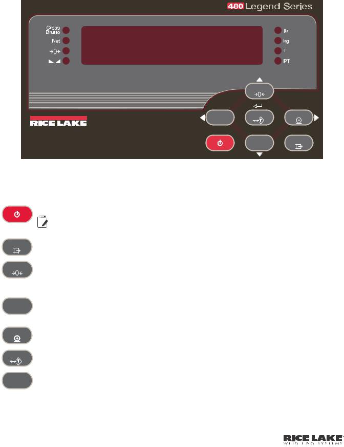
1.2 Front Panel Keypad
Figure 1-1 shows the 480 LED annunciators, keypad and key functions.
The symbols shown by the keys (representing up, down, enter, left, right) describe the key functions assigned in the operating modes. The keys are used to navigate through menus, select digits within numeric values, and increment/ decrement values. See Section 3.1 for information about using the front panel keys in configuration mode.
ZERO |
|
TARE |
|
UNIT |
|
WEIGHING SYSTEMS |
|
GROSS |
MENU |
NET |
|
B/N |
|
POWER |
|
Figure 1-1. 480 Front Panel, Showing LED Annunciators and Key Functions
1.3 Keypad Functions
Key |
|
|
|
|
|
|
Function |
|
||
|
|
|
|
|
|
|
|
|
|
|
|
Turns the unit on/off. |
|
||||||||
|
|
|
|
|
|
|
If power mode is set to manual, the POWER button must be used to turn the unit on and off. If |
|
||
|
|
|
|
|
|
|
|
|||
POWER |
|
|
|
|
|
|
Note power mode is set to auto, the unit will automatically power on when it’s plugged in and the only |
|
||
|
|
|
|
|
|
|
||||
|
|
|
|
|
|
|
||||
|
|
|
|
|
|
|
||||
|
|
|
|
|
|
|
||||
|
|
|
|
|
|
|
way to turn it off is to unplug power. See Section 3.2.5. |
|
||
|
|
|
|
|
|
|
|
|
|
|
MENU |
The MENU key is used to access the User Setup menu. |
|
||||||||
|
|
|
|
|
|
|
|
|
|
|
|
|
|
|
|
|
|
|
|
|
|
ZERO |
Sets the current gross weight to zero, provided the amount of weight to be removed or added is within the |
|
||||||||
specified zero range and the scale is not in motion. The zero band is defaulted to 2% of full scale, but can be |
|
|||||||||
|
|
|||||||||
|
configured for up to 100% of full scale. |
|
||||||||
|
Also used as a “move up” key to navigate to different menu levels or used to increment a number when editing a |
|
||||||||
|
value. |
|
||||||||
|
|
|
|
|
|
|
|
|
|
|
|
Switches the weight display to an alternate unit. The alternate unit is defined in the Configuration menu, and could |
|
||||||||
UNIT |
be kg, g, lb, oz, tn, or t. |
|
||||||||
|
Also used as a “scroll left” key to navigate to different menus. |
|
||||||||
|
In numeric entry mode used as a “clear” key. |
|
||||||||
|
|
|
|
|
|
|
|
|
|
|
Sends “on-demand” print format out the serial port, provided the conditions for standstill are met. PRINT may be |
|
|||||||||
displayed while the unit prints. |
|
|||||||||
|
|
|||||||||
|
Also used as a “scroll right” key to navigate to different menus or to toggle to another digit when editing a value. |
|
||||||||
|
|
|
|
|
|
|
|
|
|
|
TARE |
Performs one of several predetermined Tare functions dependent on the mode of operation selected in the |
|
||||||||
TAREFN parameter. To view a stored tare, see Section 1.5.7. |
|
|||||||||
|
|
|||||||||
|
Also acts as an “enter” key for numeric or parameter entry. |
|
||||||||
|
|
|
|
|
|
|
|
|
|
|
GROSS |
Switches the display mode from gross to net, or from net to gross. If a tare value has been entered or acquired, |
|
||||||||
the net value is the gross weight minus the tare. |
|
|||||||||
NET |
|
|||||||||
B/N |
Gross mode is shown by the Gross/Brutto annunciator; net mode is shown by the Net annunciator. |
|
||||||||
|
|
|||||||||
|
Also used as a “move down” key to navigate to different menu levels or to decrement a number when editing a |
|
||||||||
|
value. |
|
||||||||
|
|
|
|
|
|
|
|
|
|
|
|
|
|
|
|
|
|
|
|
|
|
|
|
|
|
|
|
|
|
|
|
|
|
|
|
|
|
|
|
|
|
|
|
4480 Operator’s Manual
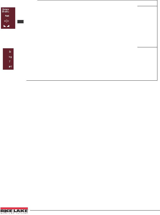
1.4 LED Annunciators
The 480 display uses a set of eight LED annunciators to provide additional information about the value being displayed.
|
|
|
|
|
LED |
Description |
|
|
|||
|
|
|
|
Gross/Brutto LED
Gross weight display mode (or Brutto in OIML mode)
Net LED
Net weight display mode
 Zero (Center of Zero) LED
The Center of Zero LED indicates that the current gross weight reading is within +/- 0.25 display divisions of the acquired zero, or is within the center of zero band.
A display division is the resolution of the displayed weight value, or the smallest incremental increase or decrease that can be displayed or printed.
 Standstill LED
Scale is at standstill or within the specified motion band. Some operations, including Zero, Tare and Printing, can only be done when the standstill LED is on.
lb/kg LED
Displays which unit of measure is being used.
lb and kg annunciators indicate the units associated with the displayed value: lb = pounds, kg = kilograms. The displayed units can also be set to short tons (tn), metric tons (t), ounces (oz), grams (g), NONE (no units information displayed). The lb and kg LEDs function as primary and secondary units annunciators. If neither
primary nor secondary units are lb or kg, the lb annunciator is lit for primary units and kg is lit for secondary units.
T LED
Indicates that a push-button tare weight has been acquired and stored in memory.
PT LED
Indicates that a preset tare weight has been keyed in or entered and stored in memory.
Table 1-1. LED Annunciators
See Section 3.3.2 for more information about configuring primary and secondary display units.
Introduction 5
1.5 Indicator Operations
Basic 480 operations are summarized below.
1.5.1Menu
Press MENU , MENU will be displayed.
Press  , then
  or
or  to select the following parameters.
•Audit Trail (See Section 1.5.10)
•Display Tare (See Section 1.5.7)
•Unit ID (See Section 1.5.11)
•Accumulator (See Section 1.5.12)
•Time and Date (See Section 1.5.13)
•Setpoints (See Section 1.5.14)
•Serial (See Section 3.2.2)
•Print Formats (See Section 7.0)
•Version (See Section 1.5.15)
•Misc. (Power Option) (See Section 3.2.5) See Section 3.2 for more information.


 Note Press
  repeatedly to return to the weigh mode.
Menus may be password protected. See Section 1.5.16 to setup a password.
1.5.2Status Lights While in Various Menus
The left side LEDs light depending on where you are in the menu levels.
Gross/Brutto |
|
Level 1 |
||||||
|
|
|
|
|
|
|
|
|
|
|
Net |
Level 2 |
|||||
( |
|
|
|
) |
|
|
|
|
|
|
|
|
|
Level 3 |
|||
|
|
|
|
|||||
|
|
|
|
|||||
( |
|
|
|
|
|
) |
|
|
|
|
|
Level 4 |
|||||
|
|
|
||||||
|
|
|
|
|
|
|
|
|
Table 1-2. Menu Levels
1.5.3Zero Scale
1. |
In gross mode, remove all weight from the scale and wait for the |
|
LED to light. |
||||
|
|||||||
2. |
Press ZERO . The |
|
|
|
LED lights to indicate the scale is zeroed. |
|
|
|
|
|
|
||||
|
|
|
|
||||
 Note See Section , INIZR parameter for Input Zero Range limitations.
1.5.4Toggle Units
1. Press UNIT to toggle between primary and secondary units. The current unit LED will be lit.
1.5.5Acquire Tare
1. Place container on scale and wait for the  LED to light.
2. Press TARE to acquire the tare weight of the container. Net weight is displayed and the T LED lights to show the tare value was entered.
See Section 9.12 for Regulatory Mode Functions.
6480 Operator’s Manual
1.5.6Preset Tare (Keyed Tare)
1. With the scale empty and display showing zero weight, press TARE .
2.Display will show (000000); the focused digit will flash.
3.To edit the value:
•Press  or
or  to select the digit.
•Press  or
or  to increment or decrement the value.
• Press TARE when the value is correct.
4. The display will change to the Net mode and the PT LED lights to show the preset tare was entered.
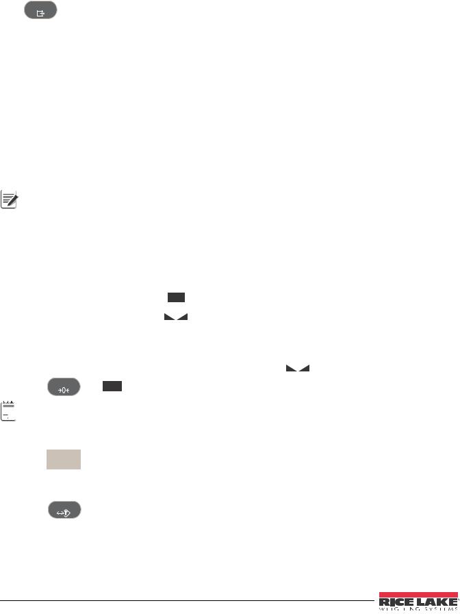
1.5.7Display Tare
When a stored Tare value is displayed, the Gross and Net LEDs will be off and the |
|
|
|
will be lit. To display a |
|
|
|
||
|
|
|
||
stored tare: |
|
|
|
|
|
|
|
|
1.Press MENU .
2.Press  to AUDIT.
3.Press  to TARE and press
  .
.
4.Press  repeatedly to return to weighing mode.
If there is no tare in the system, the value displayed will be zero and the Gross and Net LED will be turned off. See Section 9.12 for more information pertaining to the regulatory mode of operation.
1.5.8Print Ticket
1. |
Press |
to print either the Gross or Net format. When the accumulator is enabled and displayed, it is |
|||
|
used to print the accumulated value. |
||||
2. |
Wait for |
|
|
LED to light. |
|
|
|
||||
3. |
Press |
to send data to the serial port. |
|||
If |
LED is not lit and the PRINT key is pressed, the print action will take place only if the scale comes out |
||||
of motion within 3 seconds. If the scale stays in motion for over 3 seconds, the PRINT key press is ignored.
1.5.9Toggle Gross/Net Mode
1. Press to switch the display mode between gross and net. If a tare value has been entered or
B/N
acquired, the net value is the gross weight minus the tare. Gross mode — Gross/Brutto LED is lit.
Net mode — Net LED is lit.
1.5.10 View Audit Trail
See Section 3.2.
1.Press MENU .
2.Press  to AUDIT.
3.Press  . The audit trail CALIB is displayed.
4.Press  then
then  or
or  to CNT, TIME or DATE.
5.Press  to view selected parameter.
6.Press  twice to return to CALIB.
7.Press  to the audit trail CONFIG and repeat steps 5 and 6 to view configuration number.
8.Press  repeatedly to return to weighing mode.
Introduction 7
1.5.11 Enter New Unit ID
1.Press MENU .
2.Press  to AUDIT.
3.Press  twice to UNIT ID.
4.Press  to view the current value.
5.To enter/edit Unit ID value:
•Press  or
or  to select the digit.
•Press  or
or  to increment or decrement the value.
• Press TARE when the value is correct.
6. Press  repeatedly to return to weighing mode.
1.5.12 Display Accumulator
1.Press MENU .
2.Press  to AUDIT.
3.Press  until display reads ACCUM.
4.Press  to display VIEW.
5.Press  or
or  to select desired parameter (VIEW, TIME, DATE, PRINT, CLR Y).
• Press  to view last accumulation for VIEW, TIME or DATE.
• |
Press |
TARE |
to return to selected parameter. |
• |
Press |
, then |
TARE to PRINT or CLEAR the accumulator. |
6. Press |
repeatedly to return to weighing mode. |
||
See Section 3.2 for the ACCUM menu structure.


 If the accumulated value exceeds 999999, display show “EE ACC”. The value will still be correct and will print
 Note correctly up to 1,000,000,000.
1.5.13 Display or Change Time and Date
To set the date and time:
1.Press MENU .
2.Press  to AUDIT.
3.Press  until display reads TIMDAT (TIME/DATE).
4.Press  and select Time or Date with
  or
or  .
.
5.Press  to view the current setting.
6.To edit the value of the time in 24 hour or 12 hour format (hhmm):
•Press  or
or  to select the digit.
•Press  or
or  to increment or decrement the value.
• Press TARE when the value is correct.
Use the same procedure to enter the date in the same format configured for the indicator. See Section 3.3.4 for available formats.
|
|
7. Press |
repeatedly to return to weighing mode. |
||||||||
|
|
|
|
|
|
|
Note |
The time and date are backed up with an internal battery. If the main power is interrupted, time and date will |
|||
|
|
|
|
|
|
|
|||||
|
|
|
|
|
|
|
not be lost. |
||||
|
|
|
|
|
|
|
|||||
|
|
|
|
|
|
|
|||||
|
|
|
|
|
|
|
|||||
|
|
|
|
|
|
|
|||||
|
|
|
|
|
|
|
|
When in 12 hour format, the PT LED indicates pm setting. |
|||
|
|
|
|
|
|
|
|
|
|
|
|
|
|
|
|
|
|
|
|
|
|
|
|
|
|
|
|
|
|
|
|
|
|
|
|
8480 Operator’s Manual

1.5.14 Display, Edit and Set Setpoint Value
(Also see Section 8.0.)
1.Press MENU .
2.Press  to AUDIT.
3.Press  until display reads SETPNT.
4.Press  and navigate across to desired setpoint number (1-8).
5.Press  and navigate across to select User.
6.Press  and navigate across to select Enable, Value, PreAct or Hysteresis.
7.Press  to view and edit the value.
•To edit Value, PreAct or Hyster:
-Press  or
or  to select the digit.
-Press  or
or  to increment or decrement the value.
- Press TARE when the value is correct.
•To edit ENABLE:
- Press  or
or  to select ON/OFF.
- Press TARE when the value is correct.
8. Press  repeatedly to return to weighing mode. See Section 3.2.1 for the SETPNT menu layout.
1.5.15 View Version
1.Press MENU .
2.Press  . AUDIT is displayed.
3.Press  until display reads VERS.
4.Press  . FIRMW is displayed.
5.Press  to view version.
6.Press  repeatedly to return to weighing mode.
1.5.16 Enter User Password
1.Remove the large fillister head screw from the back of the enclosure.
2.Insert a nonconductive tool into the access hole and press the configuration switch. Indicator display changes to show CONFIG.
3.Press  or
or  until PASWRD is displayed.
4.Press  . CNFG is displayed.
5.Press  to USER.
6.Press  . 000000 is displayed.
7.To edit the password:
•Press  or
or  to select the digit.
•Press  or
or  to increment or decrement the value.
• Press TARE when the value is correct.
8.Press  to return to PASWRD.
9.Press  to CONFIG.
10.Press  to return to weighing mode.
When entering a user function, the operator will now be required to enter the password.
 Important Enter 999999 to reset password, this will also reset the configuration back to default values.
Introduction 9
2.0Installation
2.1Unpacking and Assembly
Immediately after unpacking, visually inspect the 480 to ensure all components are included and undamaged. The shipping carton should contain the indicator, this manual, and a parts kit. If any parts were damaged in shipment, notify Rice Lake Weighing Systems and the shipper immediately.
See Section 2.7 on page 16 for parts kit contents.
2.2 Enclosure Disassembly
The indicator enclosure must be opened to connect the scale load cell cable and any other interface connection.
 WARNING Before opening the unit, ensure the power cord is disconnected from the power outlet.
Ensure power to the indicator is disconnected, then place the indicator facedown on an antistatic work mat. Remove the screws that hold the backplate to the enclosure body. Then lift the backplate away from the enclosure and turn it over to access boards.
The display cord will still be attached. Be careful when lifting and turning over the backplate so it does not Important become damaged or dislodged.
2.3 Cable Connections
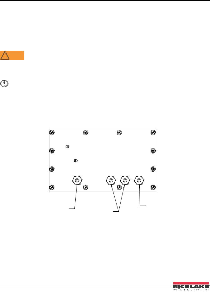
The 480 provides four cord grips for cabling into the indicator: one for the power cord, three to accommodate load cell, communications, digital inputs and outputs, and analog output cables. Two of the three free cord grips come with a plug installed to prevent moisture from entering the enclosure. Depending on your application, remove the plug from any cord grip that will be used and install cables as required. Figure 2-1 shows the recommended assignments for the 480 cord grips.
6HW 8S 6ZLWFK $FFHVV 6FUHZ
%DFN RI ,QGLFDWRU
3RZHU |
&RPPXQLFDWLRQV |
/RDG &HOO |
&RUG |
$FFHVV &RUG *URXS |
&DEOH &RUG |
|
3OXJJHG |
*ULS 2SHQ |
Figure 2-1. Recommended Cord Grip Assignments
10 480 Operator’s Manual

2.3.1 Cable Grounding
Except for the power cord, all cables routed through the cord grips should be grounded against the indicator enclosure. Do the following to ground shielded cables:
•Use the ground clamp screws to install grounding clamps on the grounding bar. Do not tighten screws yet.
•Route cables through cord grips and grounding clamps to determine cable lengths required to reach cable connectors. Mark cables to remove insulation and shield as described below:
•For cables with foil shielding, strip insulation and foil from the cable 1/2 (15 mm) past the grounding clamp (see Figure 2-2). Fold the foil shield back on the cable where the cable passes through the clamp. Ensure silver (conductive) side of foil is turned outward for contact with the grounding clamp.
•For cables with braided shielding, strip cable insulation and braided shield from a point just past the grounding clamp. Strip another 1/2 (15 mm) of insulation to only expose the braid where the cable passes through the clamp (see Figure 2-2).
•For load cell cables, cut the shield wire just past the grounding clamp. Shield wire function is provided by contact between the cable shield and the grounding clamp.
•Route stripped cables through cord grips and grounding clamps. Ensure shields contact grounding clamps as shown in Figure 2-2. Tighten ground clamp screws.
Ground |
|
clamp screw |
|
Grounding |
|
clamp |
|
Grounding |
|
bracket |
Grounding |
|
clamp |
Ground |
|
clamp screw 480 Indicator |
|
Back Panel |
Shield wire (cut)
Length of foil before folding back on cable insulation
Cut insulation here  for foil sheilded cables
Silver out side
 Braid
Braid
Cut insulation here
Foil Insulated Wire |
Braided Cable |
Figure 2-2. Grounding Clamp Attachment for Foil-Shielded and Braided Cabling
Installation 11
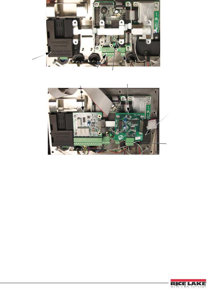
2.3.2Wiring
 A/D Board
 Option Card
Bracket
Power Supply |
|
Comm 1 & 2 |
20mA Communication |
Connection |
CPU Board Connection |
Relay (D/O) Board |
Analog Output Board |
|
Load Cell Connection
Under Option Card
1 I/O 15
Analog Output
Connection
Figure 2-3. 480 Board Options
12 480 Operator’s Manual
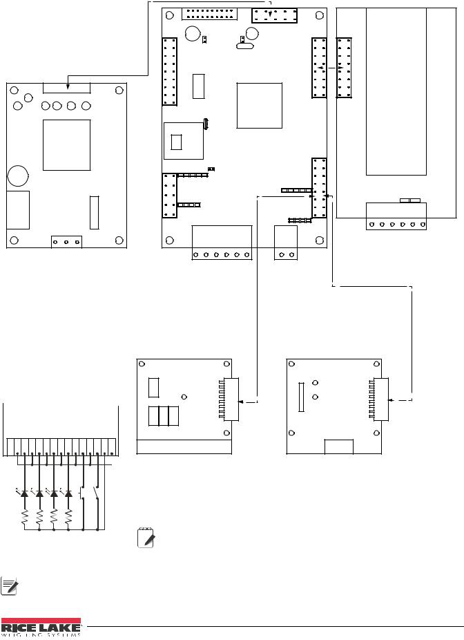
|
|
|
CPU Board PN 131318 |
A/D Board PN 131319 |
||||||
|
|
|
|
|
|
|
|
|||
|
|
|
J2 |
|
|
J10 |
|
|
|
|
|
|
|
|
|
|
|
|
|
|
|
Power Supply PN 131316 |
|
|
|
|
|
|
|
|
||
|
|
|
|
|
|
|
|
J1 |
|
|
|
|
|
J7 to display board |
|
|
|
|
|
|
|
|
|
|
J15 |
|
|
|
|
|
|
|
|
|
|
|
|
|
J5 |
|
|
|
|
|
|
|
J16 |
|
|
|
|
|
J3 |
J4 |
|
|
|
|
|
|
|
|
|
|
|
|
|
|
|
|
|
|
J6 |
|
|
J2 |
|
|
|
|
|
|
|
|
|
|
|
|
|
|
J14 |
J17 |
|
J13 |
|
|
|
|
|
GND |
|
|
GND |
|
|
|
Sig+ |
SIGSEN+ SEN- |
EXC+ EXC- |
L |
N |
|
|
|
|
Load Cell Connection |
||||
|
|
|
RXD1 |
RSTXD1 -232RXD2 |
TXD2 GND |
20mAOut |
GND |
|||
Power Supply |
|
|
|
|||||||
|
|
|
|
|
|
|
|
|||
|
|
|
|
Connection |
20mA |
|
|
|
||
|
|
|
|
|
|
Connection |
|
|
|
|
Relay Board
Wired for TTL
R1R1R1R2R2R3R3R4R4ININ _________-IN1+-IN2+_+5VGND NCCNOCNOCNOCNOOUT
1k |
1k |
1k |
1k |
BATSTART |
BATRUN |
Analog Output
Relay Board PN 131342 |
PN 131341 |
|
|
J3 |
|
 J2
J2
J2
R1_NC R1_C R1_NO R2_C R2_NO R3_C R3_NO |
R4_C R4_NO ININ1+ ININ2+ +5V_OUT GND |
I_OUT RETURN V_OUT RETURN |
|||||||
|
|
|
|
|
|
|
I/O Terminal |
Analog Output Terminal |
|
|
|
|
|
|
|
|
|
||
|
|
|
|
|
|
|
Note |
Analog and Relay boards require an option |
|
|
|
|
|
|
|
|
|||
|
|
|
|
|
|
|
card bracket (PN131340) for mounting. |
||
|
|
|
|
|
|
|
|||
|
|
|
|
|
|
|
|||
|
|
|
|
|
|
|
|||
|
|
|
|
|
|
|
|||
Figure 2-4. Wiring Diagram


 Note Output relay rating of relay
 2 AMPS at 30 VDC
Installation 13
2.4 Option Card Installation
To install or replace the Analog Output Module (PN 131341, connector PN 76513) or Relay Board (PN 131342, connector PN 157223):
1.Disconnect power to the indicator. Remove backplate as described in Section 2.2 on page 10.
2.If not already in place, install an option card bracket (PN 131340). See Figure 2-3.
3.Mount the analog output module or relay card on the option card bracket in Figure 2-3.
4.Plug the module input into connector J13 on the CPU board.
5.Connect output cable to the analog output for either current or voltage (see Section 9.10 on page 59).
 Note
Note
 Note
Note
Output relay rating of relay
2 AMPS at 30 VDC
Either slot position can be used for Analog Output Option. If slot one already has an option card in place, use slot 2.
2.5 Board Removal
If you must remove any 480 board, use the following procedure:
1.Disconnect power to the indicator. Remove backplate as described in Section 2.2 on page 10.
2.Disconnect board from power supply cable.
3.Unplug connectors. Label connections for reinstallation of board.
4.Remove the four screws from the board, then lift the board off the backplate.
To install a board, reverse the above procedure. Be sure to reinstall cable ties to secure all cables inside the indicator enclosure.
 Note When removing lower boards, the upper boards and option bracket, if installed, will need to be removed first.
2.6 Enclosure Reassembly
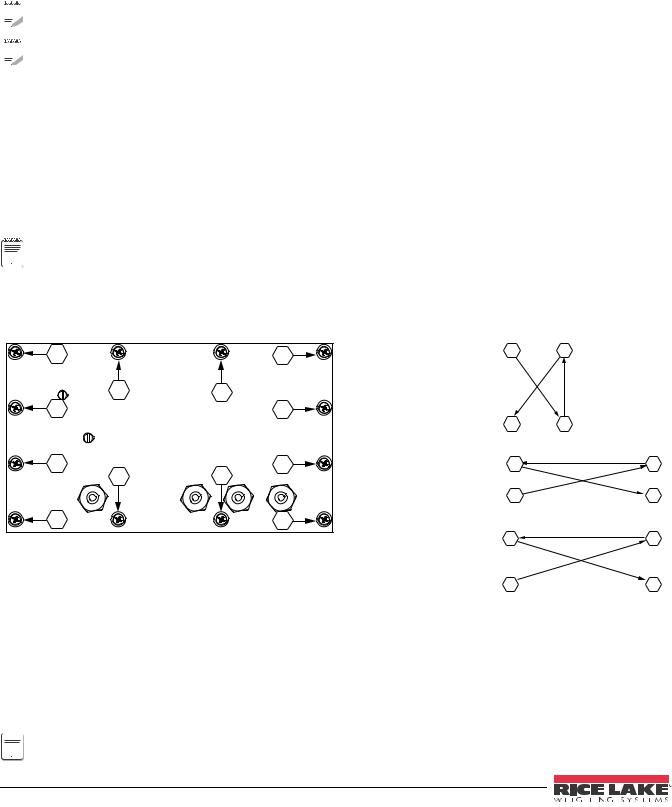
Once cabling is complete, position the backplate over the enclosure and reinstall the backplate screws. Use the torque pattern shown in Figure 2-5 to prevent distorting the backplate gasket. Torque screws to 10 in-lb (1 N-m).
11 |
10 |
1 |
3 |
7 |
6 |
5 |
8 |
4 |
2 |
9 |
12 |
Step 1. |
1 |
3 |
|
|
|
Torque 1-4 in the order shown |
|
|
|
4 |
2 |
Step 2. |
7 |
6 |
|
|
|
Torque 5-8 in the order shown |
|
|
|
5 |
8 |
|
11 |
10 |
|
|
|
Step 3. |
|
|
|
|
|
Torque 9-12 in the order shown |
|
|
Torque |
in-lb |
Nm |
|
||
9 |
12 |
||||
|
|
|
|||
|
|
|
|||
Backplate screws |
10 |
1 |
|
|
|
|
|
|
|
|
|
Cable Glands |
22 |
2.5 |
|
|
|
|
|
|
|
|
|
Cable Gland Caps |
13.3 |
1.5 |
|
|
|
|
|
|
|
|
|
Vent |
5-7 |
0.6-0.8 |
|
|
|
|
|
|
|
|
Table 2-1. Torque Values
Figure 2-5. 480 Enclosure Backplate


 Torqued screws may become less tight as the gasket is compressed during torque pattern; a second torque is
 Note required using the same pattern and torque value.
14 480 Operator’s Manual
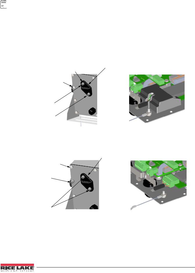
2.6.1 Seal the Indicator
 Note For access to configuration parameters, the setup switch must be pressed.
Allows Service Access
The calibration cover is used for inserting a lead wire seal through both fillister screws and the plastic cover. The cover allows access to the electronics and electrical contacts, while preventing access into Legal for Trade configuration parameters.
There is an alternative cover over the A/D to ensure the A/D and load cell connection cannot be changed after the unit is sealed.
There is also an audit trail counter to track calibration and configuration changes made to legally relevant parameters.
Place the Calibration Cover on the backplate and secure with the existing fillister head screws and o-rings to seal the indicator for Legal for Trade approval.
|
Setup Switch |
Calibration Cover |
|
Access |
for Hardware Sealing |
12 - Screw, Pan Cross Head |
|
|
8-32NC |
|
|
1 - Screw, 8-32 drilled |
|
|
fillister head |
|
|
1 - Screw, 4-40 drilled |
|
|
fillister head |
|
|
With A/D cover
Allows Service Access
Calibration Cover for Hardware Sealing
11 - Screw, Pan Cross Head
8-32NC
1 - Screw, 8-32 drilled fillister head
2 - Screw, 8-32 drilled
Without A/D cover
fillister head
Prevents Service Access
Figure 2-6. Sealing the Indicator
Prevents Service Access
The calibration cover is used for inserting a lead wire seal through 3 fillister screws. This prevents access to the electronics, electrical contacts, and Legal for Trade configuration parameters.
Installation 15

2.7 Replacement Parts
|
3 |
2 |
1 |
|
|
4 |
|
|
|
|
5 |
1 |
|
|
|
6 |
|
|
|
|
7 |
|
|
|
|
4 |
|
|
|
|
7 |
|
4 |
|
|
|
4 |
|
|
|
|
7 |
18 |
19 |
|
|
|
||
12 |
11 |
4 |
|
|
8
16 
17
10
Representation only. Actual boards may look different.
|
|
|
23 |
|
|
20 |
24 |
9 |
22 |
21 |
25 |
|
|||
|
|
|
26 |
3
27
28
29

 15
15
14
13
Figure 2-7. Replacement Parts
16 480 Operator’s Manual
Item No. |
Part No. |
Description |
QTY |
|
|
|
|
|
|
|
|
1 |
131322 |
Battery Bracket assembly, 480 |
1 |
|
|
(Future Version) |
|
|
|
|
|
2 |
131323 |
Battery, 480 lithium |
1 |
|
|
rechargeable battery (Future |
|
|
|
Version) |
|
|
|
|
|
3 |
131322 |
Backplate, 480 back plane |
1 |
|
|
base 304SS |
|
|
|
|
|
4 |
14626 |
Nut, Kep 8-32 NC Hex |
4 |
|
|
|
|
5 |
131326 |
Washer, lock LW Type A |
1 |
|
|
external tooth, steel zinc plated |
|
|
|
0.112 |
|
|
|
|
|
6 |
131328 |
Screw, pan cross head 4-40 x |
1 |
|
|
0.3125 steel zinc plated |
|
|
|
|
|
7 |
131333 |
Ground clamp |
3 |
|
|
|
|
8 |
131334 |
Ground wire, 480 insulated |
|
|
|
|
|
9 |
131340 |
Bracket for option module |
1 |
|
|
|
|
10 |
131341 |
Analog output, 0-10 VDC, |
1 |
|
|
4-20 mA |
|
|
|
|
|
|
131342 |
Relay board, 2 digital inputs, 4 |
1 |
|
|
dry contact relays |
|
|
|
|
|
11 |
131326 |
Washer, lock LW Type A, |
8 |
|
|
external tooth, steel zinc plated |
|
|
|
0.112 |
|
|
|
|
|
12 |
131328 |
Screw, pan cross head, 4-40 x |
8 |
|
|
0.3125 steel zinc plated |
|
|
|
|
|
13 |
131345 |
Overlay, 480 6-key red window, |
1 |
|
|
membrane panel |
|
|
|
|
|
14 |
131343 |
Enclosure, 480 front |
1 |
|
|
|
|
15 |
131346 |
Display board, 480 LED 7 |
1 |
|
|
segment |
|
|
|
|
|
16 |
131316 |
Power supply, switching |
1 |
|
|
85-265 VAC input, 6 VDC |
|
|
|
output |
|
|
|
|
|
17 |
131317 |
Battery charger, 480 VDC to |
1 |
|
|
VDC (Future Version) |
|
|
|
|
|
18 |
131318 |
Board assembly, CPU 480 |
1 |
|
|
|
|
19 |
131319 |
Board, assembly, A/D |
1 |
|
|
|
|
20 |
131324 |
Screw, 4-40 drilled fillister head, |
1 |
|
|
304SS |
|
|
|
|
|
21 |
131325 |
Screw, 8-32 drilled fillister head, |
1 |
|
|
304SS |
|
|
|
|
|
22 |
131335 |
O-ring |
2 |
|
|
|
|
23 |
15626 |
Cord-grip |
4 |
|
|
|
|
24 |
30375 |
Seal Ring, Nylon Pg9 |
4 |
|
|
|
|
25 |
131336 |
Calibration cover assembly |
1 |
|
|
|
|
26 |
131337 |
Washer, rubber |
2 |
|
|
|
|
27 |
131344 |
Gasket, 480 backplate |
1 |
|
|
|
|
28 |
131328 |
Screw, pan cross head, 4-40 x |
4 |
|
|
0.3125 steel zinc plated |
|
|
|
|
|
Table 2-2. Replacement Parts List
Item No. |
Part No. |
Description |
QTY |
|
|
|
|
|
|
|
|
29 |
131326 |
Washer, lock LW type A |
4 |
|
|
external tooth, steel zinc plated |
|
|
|
0.112 |
|
|
|
|
|
|
103462 |
2-Position Screw Terminal |
1 |
|
|
Pluggable |
|
|
|
|
|
|
76513 |
4-Position Screw Terminal |
1 |
|
|
Pluggable |
|
|
|
|
|
|
76514 |
6-Position Screw Terminal |
2 |
|
|
Pluggable |
|
|
|
|
|
|
155230 |
Ribbon Cable CPU Board to |
1 |
|
|
Display |
|
|
|
|
|
|
155231 |
Ribbon Cable CPU Board to A/ |
1 |
|
|
D |
|
|
|
|
|
|
155232 |
Ribbon Cable Power Supply to |
1 |
|
|
CPU Board |
|
|
|
|
|
|
155233 |
Ribbon Cable CPU Board to |
1 |
|
|
Option Boards |
|
|
|
|
|
|
155234 |
Power Cord 115 VAC with |
1 |
|
|
NEMA 5-15 Plug |
|
|
|
|
|
|
155235 |
Power Cord 230 VAC with Euro |
1 |
|
|
CEE 7/7 Plug |
|
|
|
|
|
Table 2-2. Replacement Parts List (Continued)
Part No. |
Description |
Qty |
|
|
|
|
|
|
94422 |
Label, Capacity |
1 |
|
|
|
53374 |
Label, Annunicators |
1 |
|
|
|
14862 |
Screw, 8-32NCx3/8 |
8 |
|
|
|
45042 |
Washer,Bonded Sealing #8 x |
8 |
|
0.375 |
|
|
|
|
76514 |
Connector, 6-Pin for Load Cell |
2 |
|
and RS232 ports |
|
|
|
|
103462 |
Connector, 2- Pin for 20 mA port |
1 |
|
|
|
131325 |
Screw, Fillister 8-32NC x ¼ |
1 |
|
|
|
131320 |
Screw, Fillister 8-32NC x ½ |
1 |
|
|
|
Table 2-3. Parts Kit PN 131314
Installation 17
Loading...