


MODUS
DRIVER’S HANDBOOK
RENAULT recommends ELF
ELF has developed a complete range of lubricants for RENAULT:
f engine oils
f manual and automatic gearbox oils
Warning: to ensure the engine operates optimally, the use
of a lubricant may be restricted to certain vehicles. Please
refer to your maintenance document.
Benefiting from the research applied to Formula 1,
lubricants are very high-tech products.
Updated with the help of RENAULT’s technical
teams, this range is perfectly compatible with the
specific features of the brand’s vehicles.
f ELF lubricants enhance
your vehicle’s performance significantly.
RENAULT recommends approved ELF lubricants for oil changes and top-ups.
Contact your RENAULT Dealer or visit www.lubrifiants.elf.com
Photo credit: Total/DPPI Imacom group
Une marque de
Welcome to your new vehicle
This Driver’s Handbook contains the information necessary:
– for you to familiarise yourself with your vehicle, to use it to its best advantage and to benefit fully from the all the functions and
the technical developments it incorporates.
– to ensure that it always gives the best performance by following the simple, but comprehensive advice concerning regular main-
tenance.
– to enable you to deal quickly with minor faults not requiring specialist attention.
It is well worth taking a few minutes to read this handbook to familiarise yourself with the information and guidelines it contains
about the vehicle and its functions and new features. If certain points are still unclear, our Network technicians will be only too
pleased to provide you with any additional information.
The following symbol will help you when reading this handbook:
To indicate a hazard, danger or safety recommendation.
The descriptions of the models given in this handbook are based on the technical specifications at the time of writing. This handbook covers all items of equipment (both standard and optional) available for these models but whether or not these are
fitted to the vehicle depends on the version, options selected and the country where the vehicle is sold.
This handbook may also contain information about items of equipment to be introduced later in the model year.
Throughout the manual, the “approved Dealer” is your RENAULT Dealer.
Enjoy driving your new vehicle.
Translated from French. Copying or translation, in part or in full, is forbidden unless prior written permission has been obtained from the vehicle manu-
facturer.
0.1

0.2
C O N T E N T S
Sections
Getting to know your vehicle ...............................
Driving ...................................................................
Your comfort .........................................................
Maintenance .........................................................
Practical advice ....................................................
Technical specifications ......................................
Alphabetical index ...............................................
1
2
3
4
5
6
7
0.3

0.4

Section 1: Getting to know your vehicle
Radio frequency remote control unit: general information, use, deadlocking . . . . . . . . . . . . . . . . . . 1.2
Doors . . . . . . . . . . . . . . . . . . . . . . . . . . . . . . . . . . . . . . . . . . . . . . . . . . . . . . . . . . . . . . . . . . . . . . . . . 1.7
Automatic locking of opening elements when driving . . . . . . . . . . . . . . . . . . . . . . . . . . . . . . . . . . . . 1.11
Engine immobiliser system . . . . . . . . . . . . . . . . . . . . . . . . . . . . . . . . . . . . . . . . . . . . . . . . . . . . . . . . 1.12
Headrests - Seats . . . . . . . . . . . . . . . . . . . . . . . . . . . . . . . . . . . . . . . . . . . . . . . . . . . . . . . . . . . . . . . 1.13
Seat belts. . . . . . . . . . . . . . . . . . . . . . . . . . . . . . . . . . . . . . . . . . . . . . . . . . . . . . . . . . . . . . . . . . . . . . 1.16
Additional methods of restraint . . . . . . . . . . . . . . . . . . . . . . . . . . . . . . . . . . . . . . . . . . . . . . . . . . . . . 1.20
to the front seat belts . . . . . . . . . . . . . . . . . . . . . . . . . . . . . . . . . . . . . . . . . . . . . . . . . . . . . . . 1.20
to the rear seat belts . . . . . . . . . . . . . . . . . . . . . . . . . . . . . . . . . . . . . . . . . . . . . . . . . . . . . . . 1.24
Additional methods of side restraint . . . . . . . . . . . . . . . . . . . . . . . . . . . . . . . . . . . . . . . . . . . . . . . . . 1.25
Child safety: general information . . . . . . . . . . . . . . . . . . . . . . . . . . . . . . . . . . . . . . . . . . . . . . . . . . . . 1.27
Choosing a child seat mounting . . . . . . . . . . . . . . . . . . . . . . . . . . . . . . . . . . . . . . . . . . . . . . . 1.30
Fitting a child seat . . . . . . . . . . . . . . . . . . . . . . . . . . . . . . . . . . . . . . . . . . . . . . . . . . . . . . . . . 1.32
Deactivating/activating the front passenger airbag . . . . . . . . . . . . . . . . . . . . . . . . . . . . . . . . 1.38
Steering wheel . . . . . . . . . . . . . . . . . . . . . . . . . . . . . . . . . . . . . . . . . . . . . . . . . . . . . . . . . . . . . . . . . . 1.41
Driving position . . . . . . . . . . . . . . . . . . . . . . . . . . . . . . . . . . . . . . . . . . . . . . . . . . . . . . . . . . . . . . . . . 1.42
Instrument panel . . . . . . . . . . . . . . . . . . . . . . . . . . . . . . . . . . . . . . . . . . . . . . . . . . . . . . . . . . . . . . . . 1.46
On-board computer . . . . . . . . . . . . . . . . . . . . . . . . . . . . . . . . . . . . . . . . . . . . . . . . . . . . . . . . 1.52
Information displays. . . . . . . . . . . . . . . . . . . . . . . . . . . . . . . . . . . . . . . . . . . . . . . . . . . . . . . . . . . . . . 1.61
Clock and exterior temperature . . . . . . . . . . . . . . . . . . . . . . . . . . . . . . . . . . . . . . . . . . . . . . . . . . . . . 1.62
Rear-view mirrors . . . . . . . . . . . . . . . . . . . . . . . . . . . . . . . . . . . . . . . . . . . . . . . . . . . . . . . . . . . . . . . 1.64
Audible and visual signals . . . . . . . . . . . . . . . . . . . . . . . . . . . . . . . . . . . . . . . . . . . . . . . . . . . . . . . . . 1.66
Exterior lighting and signals. . . . . . . . . . . . . . . . . . . . . . . . . . . . . . . . . . . . . . . . . . . . . . . . . . . . . . . . 1.67
Headlight beam adjustment . . . . . . . . . . . . . . . . . . . . . . . . . . . . . . . . . . . . . . . . . . . . . . . . . . . . . . . . 1.72
Washers/Wipers . . . . . . . . . . . . . . . . . . . . . . . . . . . . . . . . . . . . . . . . . . . . . . . . . . . . . . . . . . . . . . . . 1.73
Fuel tank (filling with fuel) . . . . . . . . . . . . . . . . . . . . . . . . . . . . . . . . . . . . . . . . . . . . . . . . . . . . . . . . . 1.76
1.1
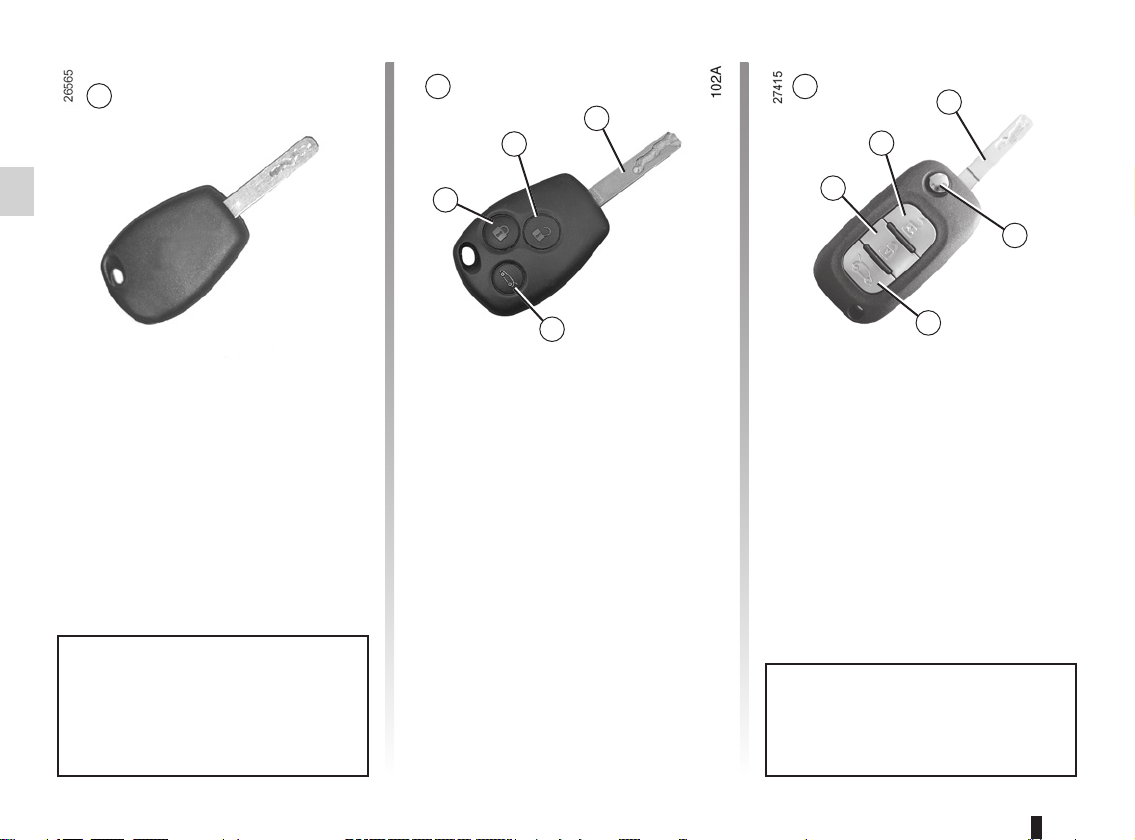
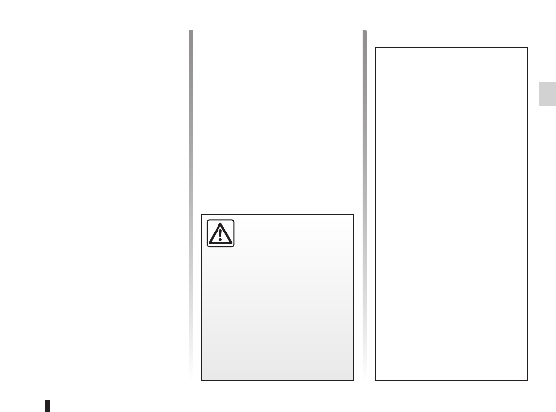
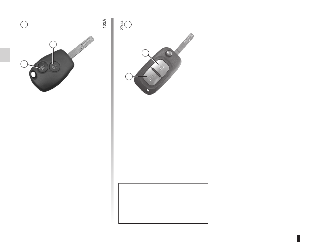
KEY/RADIO FREQUENCY REMOTE CONTROL: general information (1/2)
A
5
Key A
1 Coded key for ignition switch,
doors and fuel filler cap.
B C
3
2
1
4
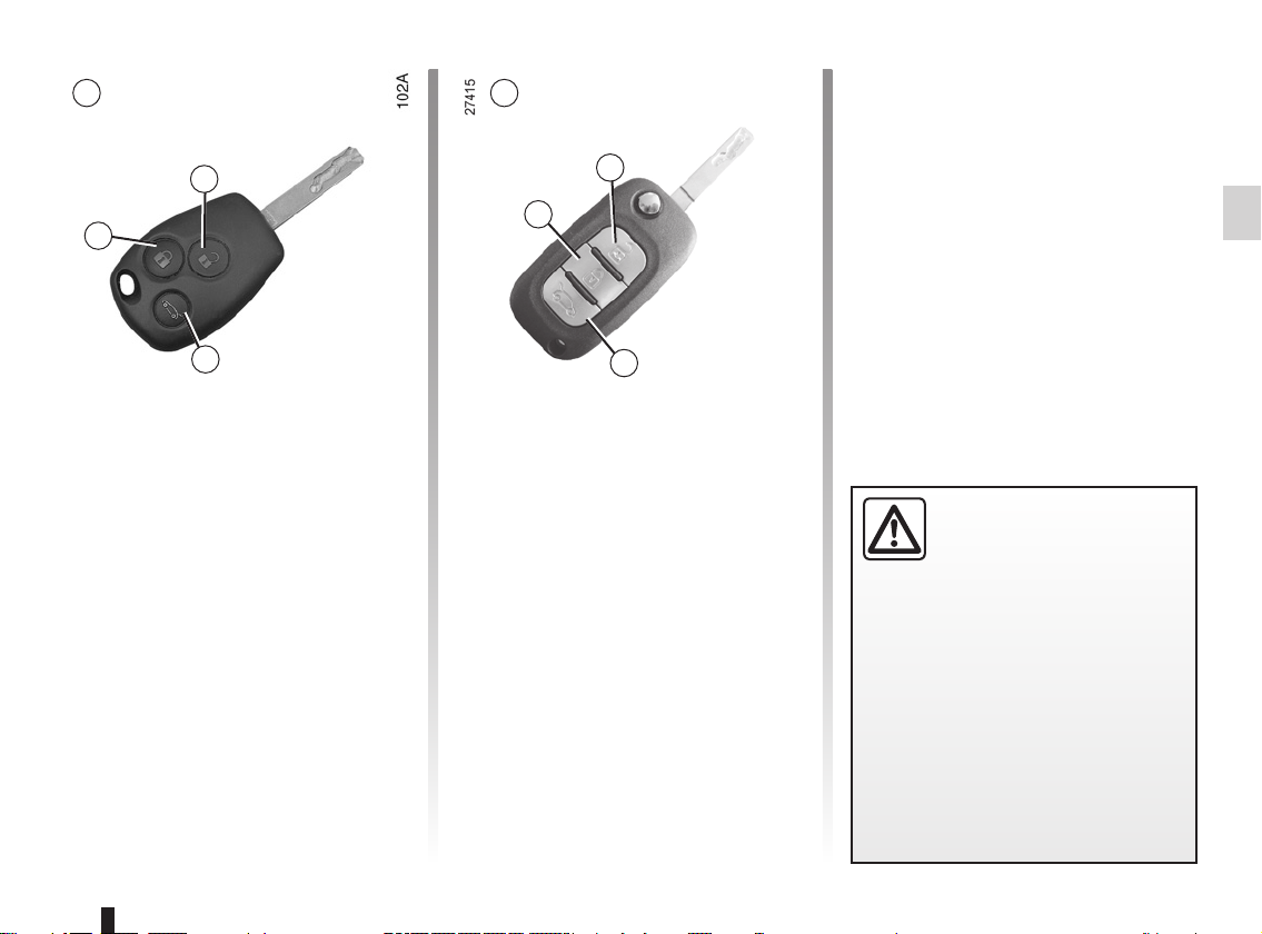
Radio frequency remote
control unit B or C
1 Locking the doors and tailgate.
2 Unlocking the doors and tailgate.
3 Driver’s door and ignition key.
3
2
1
5
4
4 Locking/unlocking the tailgate only.
5 To release the key from its hous-
ing, press button 5. It will be released automatically.
To reinsert it in its housing, press
button 5 and guide the key into the
storage position.
The key must not be used for any
function other than those described
in the handbook (removing the cap
from a bottle, etc.).
1.2
Advice
Avoid leaving the remote control in
hot, cold or humid areas.
KEY/RADIO FREQUENCY REMOTE CONTROL: general information (2/2)
Radio frequency remote
control operating range
This varies according to the environment: take care not to lock or unlock
the doors by inadvertently pressing the
buttons on the remote control.
Interference
The presence of certain objects (metal
objects, mobile telephones, or an area
with strong electromagnetic radiation,
etc.) close to the key may create interference and affect the operation of the
system.
Driver’s responsibility
Never leave your vehicle with the key inside and
never leave a child (or a
pet) unsupervised, even for a short
while.
They may pose a risk to themselves
or to others by starting the engine,
activating equipment such as the
electric windows or by locking the
doors.
Risk of serious injury.
For replacement, or if you
require an additional remote
control.
You must only contact an approved
Dealer.
– To replace a remote control, the
vehicle must be taken to an approved Dealer as both the vehicle and the remote control are
needed to initialise the system.
– Depending on the vehicle, you
have the option of using up to
four remote controls.
Remote control unit failure
Make sure that the correct battery
type is being used, and that the
battery is in good condition and inserted correctly. These batteries
have a service life of approximately
two years.
Refer to the information on the “Key,
radio frequency remote control: batteries” in Section 5 for the battery
changing procedure.
1.3
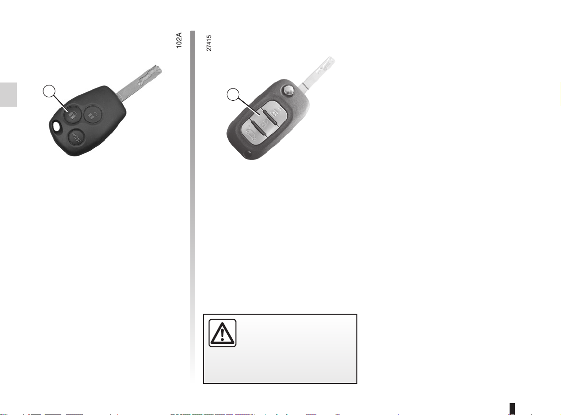
RADIO FREQUENCY REMOTE CONTROL: use (1/2)
A B
2
2
1
1
Unlocking the doors
Remote control A or B
Press unlocking button 2.
The hazard warning lights and indica-
tor lights flash once to indicate that the
doors have unlocked.
1.4
Special notes (for some countries):
– pressing button 2 enables the driv-
er’s door only to be unlocked,
– the other doors can be unlocked by
pressing button 2 twice.
The key must not be used for any
other function than those described
in the handbook (removing the cap
from a bottle, etc.).
RADIO FREQUENCY REMOTE CONTROL: use (2/2)
A
2
1
3
Locking the doors
Remote control A or B
Press locking button 1.
The indicator lights and hazard warning
lights flash twice to indicate that the
doors have locked:
If a door or the tailgate is open or not
properly shut, the doors or tailgate lock
then quickly unlock and the hazard
warning lights and indicator lights do
not flash.
B
2
1
3
Unlocking/locking the tailgate
only
(for some countries)
Press button 3 to unlock or lock the tail-
gate.
The hazard warning lights and indica-
tor lights flash once to indicate that the
tailgate is unlocked if the vehicle doors
are locked.
The hazard warning lights and indicator
lights flash twice to indicate that the tailgate is locked if the vehicle doors are
locked.
Driver’s responsibility
Never leave your vehicle with the key inside and
never leave a child (or a
pet) unsupervised, even for a short
while.
They may pose a risk to themselves
or to others by starting the engine,
activating equipment such as the
electric windows or by locking the
doors.
Risk of serious injury.
1.5
DEADLOCKING
1
Deadlocking of the doors/
tailgate
(for some countries)
This allows you to lock the doors and
tailgate and to prevent the doors from
being opened with the interior handles
(by breaking the window and then trying
to open the doors from the inside).
1
To activate deadlocking
Press button 1 twice in quick succession.
The hazard warning lights and indicator lights flash five times to indicate that
the doors have locked.
Never use deadlocking if
someone is still inside the
vehicle.
1.6

OPENING AND CLOSING THE DOORS (1/2)
1
Opening the doors from the
outside
After the vehicle has been locked using
the remote control or the key, pull
handle 1.
Opening from the inside
Pull handle 2.
Lights-on warning buzzer
If you have switched off the ignition
and left the lights switched on, a warning buzzer will sound when a door is
opened.
2
Door/tailgate open buzzer
If a door or tailgate is open or not properly closed, as soon as the vehicle
reaches a speed of approximately 12
mph (20 km/h), the message “luggage
compartment open” or “door open” (depending on what is open) will appear on
the instrument panel accompanied by a
warning light.
As a safety precaution,
the doors should only be
opened or closed when the
vehicle is stationary.
1.7

OPENING AND CLOSING THE DOORS (2/2)
Safety of rear occupants
The driver can authorise
operation of the rear doors
and, depending on the ve-
strument panel;
light up.
Driver’s responsibility when parking or stopping the vehicle
Never leave an animal, child or adult who is not self-sufficient alone on
your vehicle, even for a short time.
They may pose a risk to themselves or to others by starting the engine,
3
Child safety
Vehicles fitted with switch 3 with
integrated indicator light
Press switch 3 to inhibit operation of
the rear electric windows and opening
of the rear doors from the inside. The
indicator light in the switch confirms
that the locks have been activated.
hicle, the electric windows by pressing switch 3 on the side with the illustration.
Depending on the vehicle, in the
event of a fault:
– a beep sounds;
– a message is displayed on the in-
– the integrated indicator does not
If the battery has been disconnected, press switch 3 on the side
with the symbol, to lock the rear
doors.
activating equipment such as the electric windows or by locking the doors.
Also, in hot and/or sunny weather, please remember that the temperature inside
the passenger compartment increases very quickly.
RISK OF DEATH OR SERIOUS INJURY.
4
Vehicle with manual door locking
Move lever 4 and check from the inside
that the doors are securely locked, to
prevent the rear doors being opened
from the inside.
1.8
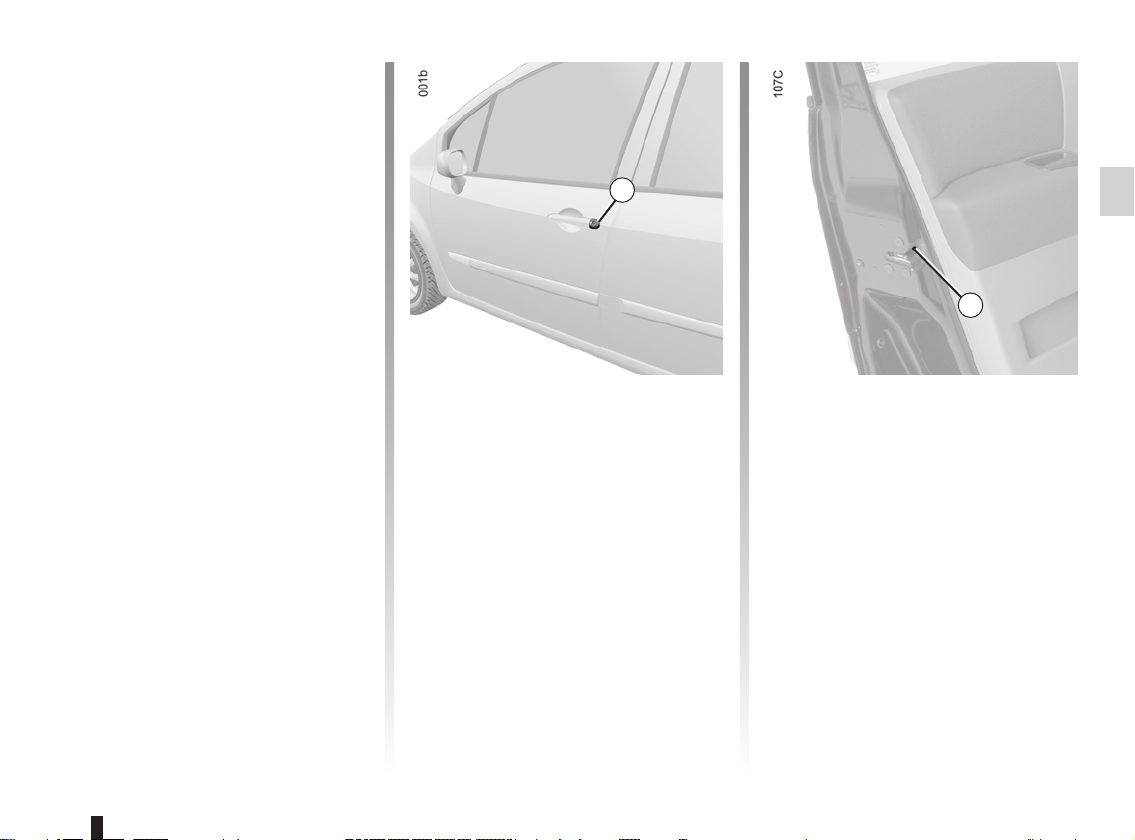
LOCKING/UNLOCKING THE DOORS (1/2)
Locking/Unlocking from the
outside
Refer to the information on the “Key,
radio frequency remote control: general
information”.
In some cases, the key/radio frequency
remote control may not work:
– if the vehicle is located in a zone of
high electromagnetic radiation;
– if the remote control battery is old or
the vehicle battery discharged.
It is then possible:
– to use the key/remote control locking
unit near to the left-hand door mirror;
– depending on the vehicle, to use the
remote control key, for the front left-
hand door only;
– to lock each of the doors manually;
– to use the interior door locking/un-
locking control (refer to the following
pages).
Using the key
Insert the key into lock 1 then lock or
unlock.
1
2
Locking the doors manually
With the door open, turn screw 2 (using
the key) and close the door.
This means that the doors are then
locked from the outside.
The doors can only be opened from the
inside by pressing the opening controls
on the inside or by using the key for the
front left-hand door.
1.9
LOCKING/UNLOCKING THE DOORS (2/2)
Locking/Unlocking doors
from the outside (continued)
Using the door locking/unlocking interior control.
With the engine switched off and a front
door open, press switch 3 for more than
five seconds.
Make sure you have your key with you
before you leave your vehicle.
When the door is closed, all the doors
and tailgate will be locked.
Unlocking from outside the vehicle will
only be possible with the key, for the
front left-hand door.
Locking/Unlocking from the
inside: button 3
This simultaneously controls the opening elements (doors and tailgate) and
the fuel filler flap.
If a door is open or not properly closed,
the doors lock and then quickly unlock.
3
To lock the vehicle leaving a door
open (eg. when transporting something in the luggage compartment
which prevents it from being closed),
or when the vehicle is located in a
zone of high electromagnetic radiation, or if the card or key is faulty:
with the engine switched off, press
and hold button 3 for more than five
seconds.
Doors and tailgate status
indicator light
The indicator light integrated in button 3
shows whether or not the doors and
tailgate are locked:
– the indicator light is on when the
doors/tailgate are locked;
– the light goes out when the doors/
tailgate are unlocked.
When you lock the doors, the indicator
light remains lit for approximately one
minute then goes out.
Driver’s responsibility
Never leave your vehicle
with the key or remote control inside.
If you decide to keep the doors
locked when you are driving, remember that it may be more difficult for those assisting you to gain
access to the passenger compartment in the event of an emergency.
1.10
AUTOMATIC LOCKING WHEN DRIVING
You can decide whether you want to
activate this function.
To activate
With the ignition on, press central
door locking button 1 for approximately
5 seconds, until you hear one beep.
To deactivate
With the ignition on, press central
door locking button 1 for approximately
5 seconds, until you hear one beep.
Driver’s responsibility
If you decide to keep the
doors locked when you are
driving, remember that it
may be more difficult for those assisting you to gain access to the
passenger compartment in the
event of an emergency.
Operating faults
If you experience an operating fault (no
automatic locking, the indicator light incorporated in button 1 does not light up
when trying to lock the doors and tailgate, etc.), firstly check that the doors
and tailgate are properly closed. If they
are properly closed, contact an approved Dealer.
1
Operating principle
After the vehicle is started, the system
automatically locks the doors when you
are driving at approximately 6 mph (10
km/h) and over.
The door can be unlocked:
– by pressing door unlocking button 1.
– by opening a door when stationary.
Note: if a door is opened or closed, it
will automatically lock again when the
vehicle reaches a speed of 6 mph (10
km/h).
1.11
ENGINE IMMOBILISER
This prevents the vehicle being
driven by anyone not in possession
of the vehicle’s coded ignition key.
The vehicle is automatically protected
a few seconds after the engine is
switched off.
Any unauthorised work
carried out on the engine
immobiliser (computers,
wiring, etc.) could be dangerous. Work must be carried out
by qualified personnel.
1.12
1
Operating principle
When the engine is started, warning
light 1 remains lit for a few seconds
then goes out (refer to the information
on “Starting the engine” in Section 2).
If the code is not recognised, the warning light flashes rapidly and the vehicle
will not start.
1
Vehicle protection tell-tale light
After the ignition has been switched off,
warning light 1 flashes and the vehicle
is protected.
Operating fault warning light
If the warning light continues to flash or
stays lit up permanently following an attempt to start the engine, this indicates
a fault in the system.
In this case, use the second key (supplied with the vehicle). If the fault is still
present, contact your approved Dealer
as only an approved Dealer is qualified to repair the engine immobiliser
system.
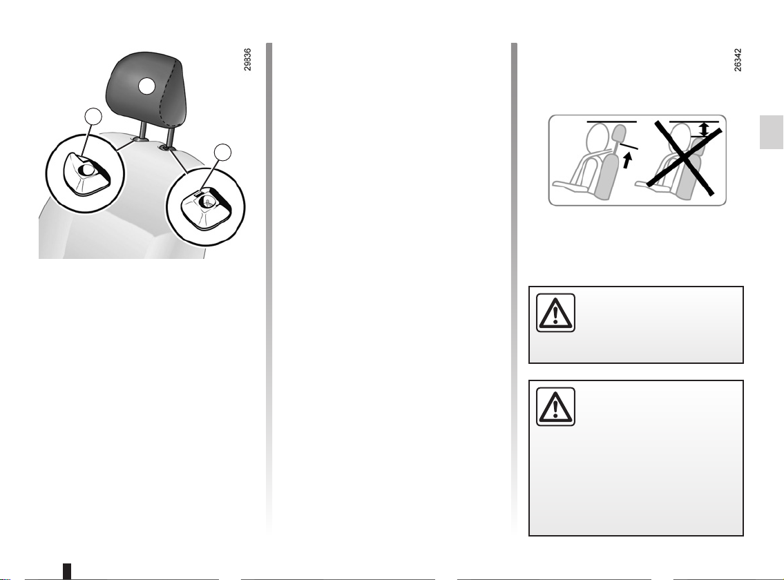
FRONT HEADRESTS
A
1
2
To raise the headrest
Slide it upwards to the required height.
To lower the headrest
Move tab 1 forwards and lower the
headrest down to the required height.
To remove the headrest
Press button 2 and lift the headrest to
release it.
To refit the headrest
Insert the headrest rods into the holes,
with the notches facing forwards.
Move tab 1 forwards and lower the
headrest down to the required height.
For safety reasons, carry
out any adjustments when
the vehicle is not being
driven.
The headrest is an important safety component:
ensure that it is in place and
in the correct position. The
distance between your head and the
headrest and the distance between
the head and section A should be
as small as possible.
1.13
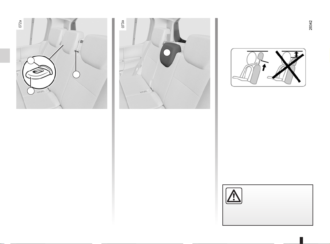
REAR HEADRESTS
A
2
1
B
Positions for use
Press tab A of lock 1 and raise the
headrest to its maximum height to use
it in the high position. Lower it until it
locks to use it in the bottom position.
Storage position
Press catch 2 and lower the headrest
completely.
When the headrest is set at the
lowest position (position B) this is
for storage only: It should not be in
this position when a seat is occupied.
1.14
To remove the headrest
Press tab A on catches 1 and 2 then
take out the headrest.
To refit the headrest
Insert the rods into the holes, press the
tabs on both rods and lower the headrest.
The headrest is a safety
component, check that it is
fitted and in the correct po-
sition.

FRONT SEATS
1
2
3
4
To move forwards or
backwards
Lift handle 1 underneath the seat to
release. Release the handle once
the seat is in the correct position and
ensure that the seat is fully locked into
position.
To tilt the seatback
Turn control knob 4 and tilt the seatback to the desired position.
Adjusting the height of the
driver’s seat
Move lever 2 as many times as necessary:
– upwards to raise it;
– downwards to lower it.
Heated seats
With the ignition switched on, press
switch 3 on the required seat. The indicator light in the switch lights up.
The system, which has a thermostat,
decides whether or not the heating is
needed.
For safety reasons, carry
out any adjustments when
the vehicle is not being
driven.
We would advise you not to recline
the seatbacks too far to ensure that
the effectiveness of the seat belts is
not reduced.
Nothing should be placed on the
floor (area in front of driver) as such
objects may slide under the pedal
during braking manoeuvres, thus
obstructing its use.
1.15
SEAT BELTS (1/4)
Always wear your seat belt when travelling in your vehicle. You must also
comply with the legislation of the particular country you are in.
Before starting, first adjust your
driving position, then ask all passengers to adjust their seat belts to
ensure optimum protection.
Incorrectly adjusted or
twisted seat belts may
cause injuries in the event
of an accident.
Use one seat belt per person,
whether child or adult.
Even pregnant women should wear
a seat belt. In this case, ensure that
the lap belt is not exerting too much
pressure on the abdomen, but do
not allow any slack.
Adjusting your driving
position
– Sit well back in your seat (having
first removed your coat or jacket).
This is essential to ensure your back
is positioned correctly;
– adjust the distance between the
seat and the pedals. Your seat
should be as far back as possible
while still allowing you to depress
the clutch pedal fully. The seatback
should be adjusted so that your arms
are slightly bent when you hold the
steering wheel;
– adjust the position of your head-
rest. For safety reasons, the top of
the headrest must be level with the
top of the head;
– adjust the height of the seat. This
adjustment allows you to select the
seat position which offers you the
best possible view;
– adjust the position of the steering
wheel.
Refer to the information on the
“Steering wheel” in Section 1.
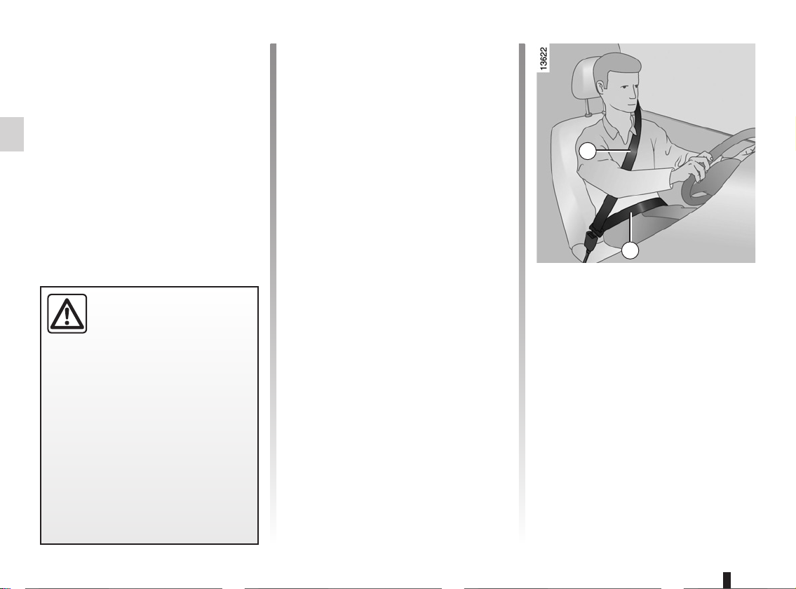
1
2
Adjusting the seat belts
Sit with your back firmly against the
seatback.
Shoulder strap 1 should be as close as
possible to the base of the neck but not
on it.
Lap belt 2 should be worn flat over the
thighs and against the pelvis.
The belt should be worn so that it is
as close as possible to your body, i.e.:
avoid wearing heavy clothing or keeping bulky objects under the belts, etc.
1.16
SEAT BELTS (2/4)
If your seat belt is completely jammed,
pull slowly, but firmly so that just over
3 cm unwinds. Allow it to return slightly
before attempting to unwind it again.
If there is still a problem, contact an approved dealer.
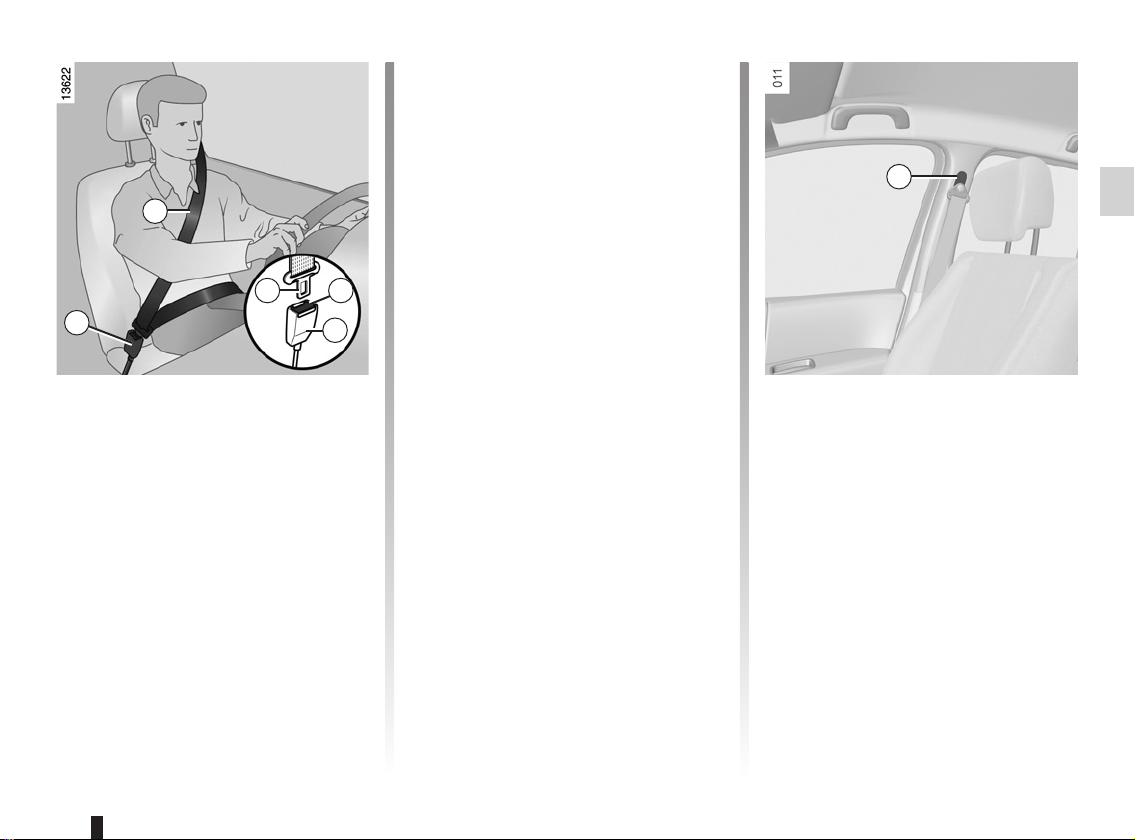
6
1
3
5
4
5
To fasten
Unwind the belt slowly and smoothly
and ensure that buckle 3 locks into
catch 5 (check that it is locked by pulling on buckle 3).
If the belt jams before it clicks in, allow
it to return before attempting to unwind
it again.
ç
This warning light on the instrument
panel or dashboard goes out to let you
know that the seat belt has been correctly fastened.
Seat belt reminder
warning light
Unlocking
Press button 4 on catch 5 and the seat
belt will be rewound by the inertia reel.
Guide the buckle to help the operation.
Adjusting the height of the
seat belt
Move button 6 to select the position you
require so that chest strap 1 is worn as
described above.
Make sure that the seat belt is locked
in position correctly after you have adjusted it.
1.17
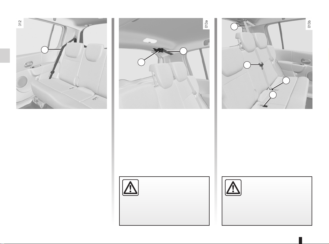
SEAT BELTS (3/4)
9
7
Rear side seat belts 7
The belts are locked, unlocked and
adjusted in the same way as the front
belts.
9
8
Rear centre belt
Unwind belt 9 slowly from its housing,
then fasten buckle 8 into the corresponding black catch 11.
Make sure that the rear
bench seats are locked in
position properly so that the
seat belts will operate efficiently. Refer to the information on
the “Rear bench seats” in Section 3.
10
11
12
Fasten sliding buckle 10 into the corresponding red catch 12.
Check that the rear seat
belts are positioned and
operating correctly each
time the rear bench seat is
moved.
1.18
SEAT BELTS (4/4)
The following information applies to the vehicle’s front and rear seat belts.
– No modification may be made to the component parts of the originally fitted restraint system: belts, seats and their
mountings. For special operations (e.g. fitting child seats), contact an authorised dealer.
– Do not use devices which allow any slack in the belts (e.g. clothes pegs, clips, etc.): a seat belt which is worn too
loosely may cause injury in the event of an accident.
– Never wear the shoulder strap under your arm or behind your back.
– Never use the same belt for more than one person and never hold a baby or child on your lap with your seat belt around
them.
– The belt should never be twisted.
– Following an accident, have the seat belts checked and replaced if necessary. Always replace your seat belts as soon as
they show any signs of wear.
– When putting back the rear bench seat, make sure the seat belts are correctly positioned so that they can be used properly.
– Make sure that the buckle is inserted into the appropriate catch.
– Ensure that no objects are placed in the area around the seat belt catch as they could prevent it from being properly se-
cured.
– Make sure the seat belt catch is properly positioned (it should not be hidden away, crushed or flattened by people or ob-
jects).
1.19
METHODS OF RESTRAINT IN ADDITION TO THE FRONT SEAT BELTS (1/4)
These are:
– pretensioners,
– chest and lap belt force limiters,
– air bags for driver and front pas-
senger.
These systems are designed to operate
independently or together in the event
of a front, side or rear impact.
Depending on the severity of the
impact, the system can trigger:
– seat belt locking;
– the lap belt pretensioner to keep
the occupant in their seat, the low
volume front air bag and the force
limiter;
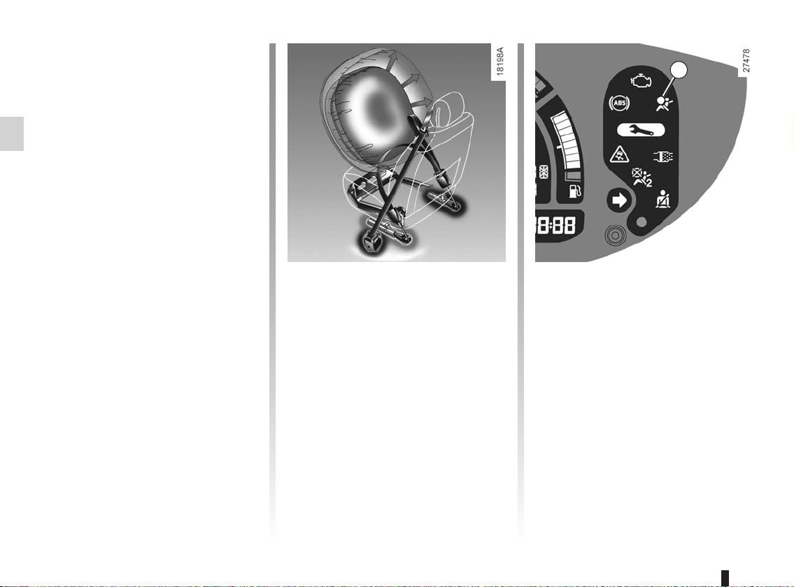
– the large volume air bag.
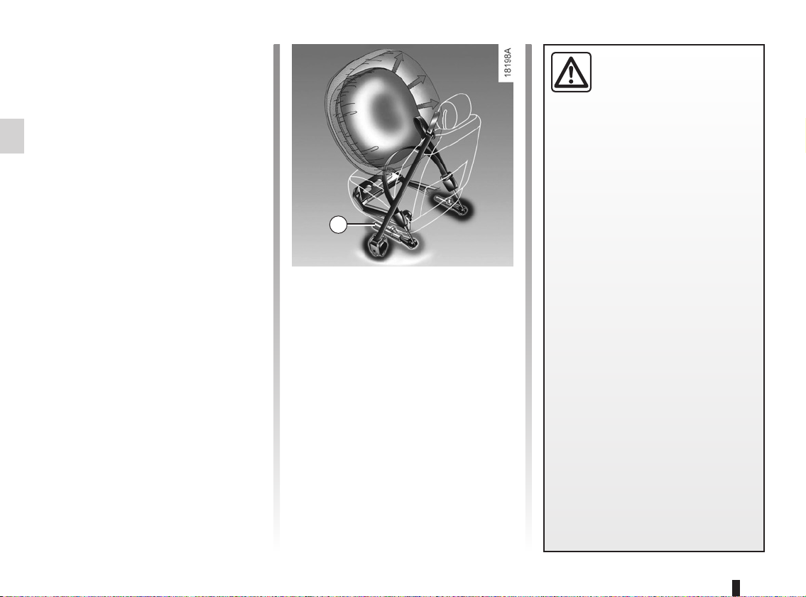
1
Pretensioners
With the ignition switched on, if the vehicle is subjected to a significant frontal
impact the system may, depending on
the severity of impact, trigger piston 1
which instantly retracts the belt.
The pretensioners flatten the belt
against the body, holding the occupant
against the seat, thus improving the efficiency of the belt.
– Have the entire restraint
system checked following
an accident.
– No operation whatsoever is permitted on any part of
the system (pretensioners, air
bags, computers, wiring) and the
system components must not
be reused on any other vehicle,
even if identical.
– To avoid incorrect triggering of
the system which may cause
injury, only qualified personnel
from an approved dealer may
work on the pretensioner and air
bag system.
– The electric trigger system may
only be tested by a specially
trained technician using special
equipment.
– When the vehicle is scrapped,
contact an approved dealer for
disposal of the pretensioner and
air bag gas generators.
1.20
METHODS OF RESTRAINT IN ADDITION TO THE FRONT SEAT BELTS (2/4)
Chest-level and lap belt load
limiters
Above a certain severity of impact, this
mechanism is used to limit the force of
the belt against the body so that it is at
an acceptable level.
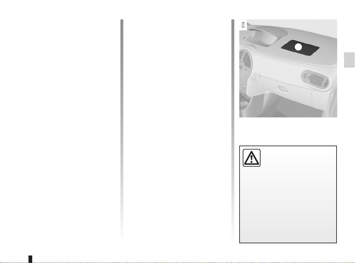
Air bags for driver and front
passenger
Fitted to the driver and passenger side.
The presence of this equipment is in-
dicated by the word “Air bag” on the
steering wheel and the dashboard (air
bag zone A) and, depending on the vehicle, a label on the lower part of the
windscreen.
Each air bag system consists of:
– an air bag and gas generator fitted
on the steering wheel for the driver
and in the dashboard for the front
passenger;
– an electronic unit for system monitor-
ing which controls the gas generator
electrical trigger system;
– a single
instrument panel.
– remote sensors.
å warning light on the
A
The air bag system uses
pyrotechnic principles. This
explains why, when the air
bag inflates, it will gener-
ate heat, produce smoke (this does
not mean that a fire is about to start)
and make a noise upon detonation.
In a situation where an air bag is
required, it will inflate immediately
and this may cause some minor, superficial grazing to the skin or other
problems.
1.21
METHODS OF RESTRAINT IN ADDITION TO THE FRONT SEAT BELTS (3/4)
Operation
This system is only operational when
the ignition is switched on.
In a severe frontal impact, the air bags
inflate rapidly, cushioning the impact
of the driver’s head and chest against
the steering wheel and of the front passenger against the dashboard. The air
bags then deflate immediately so that
the passengers are not in any way hindered from leaving the vehicle.
1
1.22
Special feature of the front air
bag
There are two volumes of operation depending on the severity of the impact:
– low volume air bag, this is the first
stage of operation;
– large volume air bag, the straps are
torn in order to allow the air bag to inflate to a higher volume (in the event
of more severe impacts).
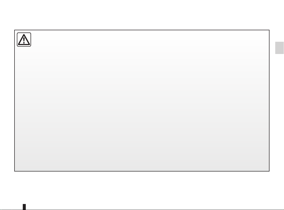
Operating faults
Warning light 1 will light up on the instrument panel when the ignition is
switched on and then go out after a few
seconds.
If it does not light up when the ignition
is switched on, or comes on when the
engine is running, there is a fault in the
system.
Contact your approved Dealer as soon
as possible. Your protection will be reduced until this fault is rectified.
METHODS OF RESTRAINT IN ADDITION TO THE FRONT SEAT BELTS (4/4)
All of the warnings below are given so that the air bag is not obstructed in any way when it is inflated and also to prevent
the risk of serious injuries caused by items which may be dislodged when the air bag inflates.
Warnings concerning the driver’s air bag
– Do not modify the steering wheel or the steering wheel boss.
– Do not cover the steering wheel boss under any circumstances.
– Do not attach any objects (badge, logo, clock, telephone holder, etc.) to the steering wheel boss.
– The steering wheel must not be removed (except by qualified personnel from our Network).
– When driving, do not sit too close to the steering wheel. Sit with your arms slightly bent (see the information on “Adjusting
your driving position” in Section 1). This will allow sufficient space for the air bag to deploy correctly and be fully effective.
Warnings concerning the passenger air bag
– Do not attach or glue any objects (badge, logo, clock, telephone holder, etc.) to the dashboard on or near the air bag.
– Do not place anything between the dashboard and the passenger (pet, umbrella, walking stick, parcels, etc.).
– The passenger must not put his or her feet on the dashboard or seat as there is a risk that serious injuries may occur. In
general, parts of the body should be kept away from the dashboard (knees, hands, head, etc.).
– The devices in addition to the front passenger seat belt should be reactivated as soon as a child seat is removed, to ensure
the protection of the passenger in the event of an impact.
A CHILD SEAT MUST NOT BE FITTED TO THE FRONT PASSENGER SEAT UNLESS THE
ADDITIONAL RESTRAINT SYSTEMS, I.E. THE PASSENGER AIR BAG, ARE DEACTIVATED.
(refer to Section 1 “Child safety: deactivating/activating the front passenger air bag”)
1.23
METHODS OF RESTRAINT IN ADDITION TO THE REAR SEAT BELTS
Force limiter
Above a certain severity of impact, this
mechanism is used to limit the force of
the belt against the body so that it is at
an acceptable level.
– Have the entire restraint
system checked following
an accident.
– No operation whatsoever
is permitted on any part of the
system (air bags, electronic control units, wiring) and the system
components must not be reused
on any other vehicle, even if identical.
– Only qualified personnel from
our Network may work on the air
bags; otherwise the system may
trigger accidentally and cause
injury.
1.24

SIDE PROTECTION DEVICES
Side air bags
This air bag may be fitted to each of the
front seats and is activated at the sides
of the seats (door side) to protect the
occupants in the event of a severe side
impact.
Curtain air bags
These air bags may be fitted along the
top of each side of the vehicle and are
triggered along the front and rear side
windows to protect the passengers in
the event of a severe side impact.
Depending on the vehicle, a marking on the windscreen informs you
of the presence of additional means
of restraint (air bags, pretensioners,
etc.) in the passenger compartment.
These air bags operate
through slits in the front
seatbacks (door side):
never insert any objects in
these slits.
Warnings concerning the side air bag
– Fitting seat covers: seats equipped with an air bag require covers
specifically designed for your vehicle. Contact an approved dealer to find
out if these covers are available. The use of any covers other than those
designed for your vehicle (including those designed for another vehicle) may
affect the operation of the air bags and reduce your protection.
– Do not place any accessories, objects or even pets between the seatback, the
door and the internal fittings. Do not cover the seatback with any items such as
clothes or accessories. This may prevent the air bag from operating correctly
or cause injury when the air bag is deployed.
– No work or modification whatsoever may be carried out on the seat or internal
fittings, except by qualified personnel from an approved dealer.
– The area between the rear bench seatback and the trim is the area of air bag
operation: no objects must be placed here.
1.25

ADDITIONAL METHODS OF RESTRAINT
All the warnings below are given so that air bag activation is not obstructed in any way and also to prevent the risk of
serious injuries caused by items which may be dislodged when the air bag inflates.
The air bag is designed to complement the action of the seat belt. Both the air bags and seat belts are integral parts of
the same protection system. It is therefore essential to wear seat belts at all times. If seat belts are not worn, the occupants are exposed to the risk of serious injury in the event of an accident. It may also increase the risk of minor superficial injuries occurring when the air bag is deployed, although such minor injuries are always possible with air bags.
If the vehicle should overturn or suffer a rear impact, however severe, the pretensioners and air bags are not always triggered.
Shocks to the underbody of the vehicle, e.g. from pavements, potholes or stones, can all trigger these systems.
– No work or modification whatsoever may be carried out on any part of the air bag system (air bags, pretensioners, compu-
ter, wiring harness, etc.), except by qualified personnel from an approved dealer.
– To ensure that the system is in good working order and to avoid accidental triggering of the system which may cause injury,
only qualified Network personnel may work on the air bag system.
– As a safety precaution, have the air bag system checked if your vehicle has been involved in an accident, or is stolen or
broken into.
– When selling or lending the vehicle, inform the user of these points and hand over this driver’s handbook with the vehicle.
– When scrapping your vehicle, contact your approved dealer for disposal of the gas generator(s).
1.26

CHILD SAFETY: General information (1/2)
Carrying children
Children - and adults - must be correctly
seated and strapped in for all journeys.
The children being carried in your vehicle are your responsibility.
A child is not a miniature adult. Children
are at risk of specific injuries as their
muscles and bones have not yet finished growing. The seat belt alone
would not provide suitable protection.
Use an approved child seat and ensure
you use it correctly.
Set a good example by always fastening your seat belt and teaching
your child:
– to strap themselves in correctly.
– to always get in and out of the car
at the kerb, away from busy traf-
fic.
Do not use a second-hand child
seat or one without an instruction
manual.
Check that there are no objects in
the vicinity of the child seat which
could impede its operation.
Using a child seat
The level of protection offered by the
child seat depends on its ability to restrain your child and on its installation.
Incorrect installation compromises the
protection it offers the child in the event
of harsh braking or an impact.
Before purchasing a child seat, check
that it complies with the regulations for
the country you are in and that it can
be fitted in your vehicle. Consult an approved dealer to find out which seats
are recommended for your vehicle.
Driver’s responsibility when parking or stopping the vehicle
Never leave an animal, child or adult who is not self-sufficient alone on
your vehicle, even for a short time.
They may pose a risk to themselves or to others by starting the engine, activating
equipment such as the electric windows or by locking the doors.
Also, in hot and/or sunny weather, please remember that the temperature inside
the passenger compartment increases very quickly.
RISK OF DEATH OR SERIOUS INJURY.
Before fitting a child seat, read the
manual and follow its instructions. If
you experience any difficulties during
installation, contact the manufacturer
of the equipment. Keep the instructions
with the seat.
For vehicles fitted with a TRIPTIC rear
bench seat, configuring it as a 2-seater
bench seat with the large section of the
seatback folded down prevents the remaining place being used for fitting
child seats using the vehicle seat belt,
as it is not possible to fasten it (seat belt
buckle inaccessible)
1.27

CHILD SAFETY: General information (2/2)
Never leave a child unattended in the vehicle.
Check that your child is
the belt or safety harness used is
correctly set and adjusted. Avoid
wearing bulky clothing which could
cause the belts to slacken.
Never let your child put their head or
arms out of the window.
Check that the child is in the correct
position for the entire journey, especially if asleep.
and closing the doors” in Section 1).
always strapped in and that
To prevent the doors being
opened, use the “Child
safety” device (refer to the
information on “Opening
A collision at 30 mph
(50 km/h) is the same as falling a distance of 10 metres.
Transporting a child without
a restraint is the equivalent of allowing him or her to play on a fourthfloor balcony without railings.
Never travel with a child held in your
arms. In the event of an accident,
you will not be able to keep hold of
the child, even if you yourself are
wearing a seat belt.
If your vehicle has been involved in
a road accident, replace the child
seat and have the seat belts and
ISOFIX anchorage points checked.
1.28

CHILD SAFETY: Choosing a child seat
Rear-facing child seats
A baby’s head is, proportionally, heavier
than that of an adult and its neck is very
fragile. Transport the child in this position as long as possible (until the age of
2 at the very least). It supports both the
head and the neck.
Choose a bucket type seat for best side
protection and change it as soon as the
child’s head is higher than the shell.
Forward-facing child seats
The child’s head and abdomen need to
be protected as a priority. A forward-facing child seat which is firmly attached to
the vehicle will reduce the risk of impact
to the head. Ensure your child travels in
a forward-facing seat with a harness or
buckle for as long as their size permits.
Choose a bucket type seat for optimum
side protection.w
Booster cushions
From 15 kg or 4 years, the child can
travel using a booster seat, which will
enable the seat belt to be adapted to
suit his size and shape. The booster
seat cushion must be fitted with guides
to position the seat belt on the child’s
thighs rather than the stomach. It is
recommended that you use a seatback which can be adjusted in terms
of height to position the seat belt in the
centre of the shoulder. It must never
rest on the neck or on the arm.
Choose a bucket type seat for optimum
side protection.
1.29

CHILD SAFETY: Choosing a child seat mounting
The are two ways of attaching child
seats: via the seat belt or using the
ISOFIX system.
Attachment via the seat belt
The seat belt must be adjusted to
ensure that it is effective in the event of
harsh braking or an impact.
Ensure that the strap paths indicated
by the child seat manufacturer are respected.
Always check that the seat belt is correctly fastened by pulling it up, then
pulling it out fully whilst pressing on the
child seat.
Check that the seat is correctly held by
moving it from side to side and back
to front: the seat should remain firmly
fixed.
Triptic rear bench seat
If the rear bench seat is
in the two-seater position
with the large section of the
seatback folded down, this prevents
the remaining seat being used for
the installation of a child seat using
the vehicle seat belt, as it is not possible to fasten the seat belt (seat
belt buckle not accessible).
Do not use the child seat
if it may unfasten the seat
belt restraining it: the base
of the seat must not rest on
the buckle and/or catch of the seat
belt.
The seat belt must never
be twisted or the tension
relieved. Never pass the
shoulder strap under the
arm or behind the back.
Check that the seat belt has not
been damaged by sharp edges.
If the seat belt does not operate normally, it will not protect the child.
Consult an approved dealer. Do not
use this seat until the seat belt has
been repaired.
No modifications may be
made to the component
parts of the restraint system
(belts, ISOFIX and seats
and their mountings) originally fitted.
Attachment with the ISOFIX system
Authorised ISOFIX child seats are approved in accordance with regulation
ECE-R44 in one of the three following
scenarios:
– ISOFIX universal 3-point forward-
facing seat
– ISOFIX semi-universal 2-point seat
– specific
For the latter two, check that your child
seat can be installed by consulting the
list of compatible vehicles.
Attach the child seat with the ISOFIX
locks, if these are provided. The ISOFIX
system allows quick, easy, safe fitting.
The ISOFIX system consists of 2 rings
and, in some cases, a third ring.
Before using an ISOFIX
child seat that you purchased for another vehicle,
check that its installation is
authorised. Consult the list of vehicles which can be fitted with the
seat with the equipment manufacturer.
1.30

CHILD SAFETY: Choosing a child seat mounting (continued)
5
1
2
The two rings 1 are located between
the seatback and the seat base of the
seat and are identified by a marking.
To ensure your child seat can be easily
fitted and locked on rings 1, use access
guides 2 on the child seat.
4
3
The 3rd ring is used to attach the upper
belt on some child seats.
Depending on the vehicle, to attach the
child seat belt 3:
– open the ring cover 5,
– attach the hook 4 to the ring 5 lo-
cated on the roof rear cross member
and marked by
– close the cover and tighten the belt.
Do not change the position of the bench
seat (if sliding) after tensioning the belt.
±,
The ISOFIX anchorage
points have been exclusively designed for child
seats with the ISOFIX
system. Never fit a different type of
child seat, seat belt or other objects
to these fittings.
Check that nothing is obstructing
the anchorage points.
If your vehicle has been involved in
a road accident, have the ISOFIX
fittings checked and replace your
child seat.
1.31

CHILD SAFETY: fitting a child seat (1/6)
Some seats are not suitable for fitting
child seats. The diagrams on the following pages show you how to attach
a child seat.
The types of child seats indicated may
not be available. Before using a different child seat, check with the manufacturer that it can be fitted.
Fit the child seat in a rear
seat wherever possible.
Check that when installing
the child seat in the vehicle
it is not at risk of coming loose from
its base.
If you have to remove the headrest,
check that it is correctly stored so
that it does not come loose under
harsh braking or impact.
Always attach the child seat to the
vehicle even if it is not in use so that
it does not come loose under harsh
braking or impact.
In the front seat
The laws concerning children travelling in the front passenger seat differ in
every country. Consult the legislation in
force and follow the indications on the
diagrams on the following pages.
Before fitting a child seat in this seat (if
authorised):
– lower the seat belt as far as possible;
– move the seat as far back as possi-
ble;
– gently tilt the seatback away from
vertical (approximately 25°);
– on equipped vehicles, raise the seat
base as far as possible.
Do not change these settings after the
child seat is installed.
RISK OF D EATH O R
SERIOUS INJURY: before
fitting a rear-facing child
seat in this seat, check
that the air bag has been deactivated (refer to the information on
“Deactivating the front passenger
air bags” in Section 1).
In the rear side seat
Carrycots can only be fitted in the
3-seater position and will take up at
least two seats. Position the child with
his or her feet nearest the door.
Push the vehicle seat fully forwards
to install a rear-facing child seat, then
push it back as far as possible without allowing it to make contact with the
child seat. For the safety of the child in
the forward-facing seat, do not move
the seat in front back past the middle of
the runner, do not tilt the seatback too
far (maximum of 25°) and raise the seat
as much as possible.
Always move the (sliding) bench seat
back as far as possible. The floor support of the child seat should rest of the
floor in accordance with the child seat
instructions. A booster cushion may be
fitted on the TRIPTIC bench seat, using
the ISOFIX locks and the seat belt, in
the 2-seater position only.
In rear centre seat
Seat limited to certain booster cushions
available from an approved Dealer.
Consult the booklet available from an
approved Dealer.
1.32

CHILD SAFETY: fitting a child seat (2/6)
Installation diagram
(sliding bench seats)
³ = check the status of the front
air bag before fitting a child seat
or allowing a passenger to use the
seat.
RISK OF D EATH O R
SERIOUS INJURY: before
fitting a rear-facing child
seat in the front passenger seat, check that the air bag has
been deactivated (refer to the information on “Deactivating the front
passenger air bags” at the end of
the paragraph).
Child seat attached using the belt
U = seat which allows a seat with “uni-
versal” approval to be attached
with a belt;
UD = seat which only allows a rear-
facing seat with “universal” ap-
proval to be fitted;
L = seat which allows certain booster
cushions to be fitted. Consult the
booklet available from an approved Dealer.
Child seat attached using the ISOFIX
fitting
ü = seat which allows an ISOFIX
child seat to be fitted.
± = the rear seats are fitted with
an anchorage point which allows a
forward-facing ISOFIX child seat
with universal approval to be fitted.
This is located on the roof rear
cross member under a cover.
The size of the ISOFIX child seat is indicated by a letter:
– A, B and B1: for forward-facing seats
in group 1 (9 to 18 kg);
– C: rear-facing seats in group 1 (9 to
18 kg);
– D and E: shell seat or rear-facing
seats in group 0 or 0+ (less than
13 kg);
– F and G: cots in group 0 (less than
10 kg).
Using a child safety system which is not approved for this vehicle will not
correctly protect the baby or child. They risk serious or even fatal injury.
1.33

CHILD SAFETY: fitting a child seat (3/6)
The table below summarises the information already shown on the diagram on the previous page, to ensure the regulations in force are respected.
Type of seat
Carrycot fitted across the vehicle
group 0
Rear-facing shell seat
group 0 or 0 + and 1
Forward-facing seat
group 1
Booster seat
group 2 and 3
(1) RISK OF DEATH OR
SERIOUS INJURY: before
fitting a rear-facing child
seat in the front passenger seat, check that the air bag has
been deactivated (refer to the information on “Deactivating the front
passenger air bags” at the end of
the paragraph).
Weight of
the child
< 10 kg F – G X U - IL (4) X
< 13 kg and 9
to 18 kg
9 to 18 kg A, B, B1 X
15 to 25 kg and
22 to 36 kg
large section of the seatback folded
down this prevents the remaining
seat being used for the installation
of child seats using the vehicle seat
belt, as it is not possible to fasten
the seat belt (seat belt buckle not
accessible).
ISOFIX
seat size
C, D, E U U - IL (2) (5) X
– X
(2) For vehicles fitted with
the TRIPTIC rear seat, if
the bench seat is in the
2-seater position with the
Front passenger
seat (1) (3)
Rear side
seats (7) (8)
U - IUF - IL
(2) (6)
U – IL (2)
(6) (8)
Rear centre
seat
L (2) (6)
X
1.34

CHILD SAFETY: fitting a child seat (4/6)
X = Seat not suitable for fitting child seats.
U = Seat which allows a child seat with “Universal” approval to be attached by seat belt; check that it can be fitted.
IUF/IL = On equipped vehicles, seat which allows a child seat with “universal/semi-universal or vehicle specific” approval to be
L = Seat which allows certain booster cushions to be fitted. Consult the booklet available from an approved Dealer.
(3) Only a rear-facing child seat can be fitted in this seat: position the vehicle seat as far back and raise it as much as possible,
(4) A carrycot can be installed across the vehicle and will take up at least two seats. Position the child with his or her feet nearest
(5) Push the vehicle seat fully forwards to install a rear-facing child seat, then push it back as far as possible without allowing it to
(6) Forward-facing child seat; position the seatback of the child seat in contact with the seatback of the vehicle seat. Adjust the
(7) Before fitting a child seat (excluding carrycot) on vehicles fitted with TRIPTIC bench seats, it is recommended that the bench
(8) It is not possible to fit a booster cushion using the ISOFIX anchorage points and the seat belt on the rear side seat when the
fitted using the ISOFIX system; check that it can be fitted correctly.
and tilt the seatback slightly (approximately 25°).
the door.
make contact with the child seat.
headrest, or remove it if necessary. Do not push the seat in front of the child more than halfway back on its runners and do not
recline the seatback more than 25°.
seat is put in the 2-seater position if possible (refer to information on “Rear bench seat functions” in section 3). In the 2 or
3-seater positions, move the bench seat as far back as possible, checking that the floor support of the child seat is resting on
the floor in accordance with the child seat instructions.
TRIPTIC bench seat is in the 3-seater position.
1.35

CHILD SAFETY: fitting a child seat (5/6)
Installation diagram (fixed
bench seat)
³ = check the status of the front
air bag before fitting a child seat
or allowing a passenger to use the
seat.
RISK OF D EATH O R
SERIOUS INJURY: before
fitting a rear-facing child
seat in the front passenger seat, check that the air bag has
been deactivated (refer to the information on “Deactivating the front
passenger air bags” at the end of
the paragraph).
Child seat attached using the belt
U = seat which allows a seat with “uni-
versal” approval to be attached
with a belt;
UD = seat which only allows a rear-
facing seat with “Universal” ap-
proval to be fitted;
L = seat which allows certain booster
cushions to be fitted. Consult the
booklet available from an approved Dealer.
Child seat attached using the ISOFIX
mounting
ü = seat which allows an ISOFIX
child seat to be fitted.
± = the rear seats are fitted with
an anchorage point which allows a
forward facing ISOFIX child seat
with universal approval to be fitted.
The anchoring ring is located on
the roof rear cross member under
a cover.
The size of the ISOFIX child seat is indicated by a letter:
– A, B and B1: for forward-facing seats
in group 1 (9 to 18 kg);
– C: rear-facing seats in group 1 (9 to
18 kg);
– D and E: shell seat or rear-facing
seats in group 0 or 0+ (less than
13 kg);
– F and G: cots in group 0 (less than
10 kg).
Using a child safety system which is not approved for this vehicle will not
correctly protect the baby or child. They risk serious or even fatal injury.
1.36

CHILD SAFETY: fitting a child seat (6/6)
The table below summarises the information already shown on the diagram on the previous page, to ensure the regulations in force are respected.
Type of seat
Carrycot fitted across the
vehicle
group 0
Rear-facing shell seat
group 0 or 0 + and 1
Forward-facing seat
group 1
Booster seat
group 2 and 3
X = seat not suitable for fitting child seats.
U = seat allowing a child seat with “Universal” approval to be attached by seat belt; check that it can be fitted correctly.
IUF/IL = on equipped vehicles, seat which allows a child seat with “universal, semi-universal or vehicle specific” approval to be
fitted using the ISOFIX system; check that it can be fitted correctly.
L = seat which allows certain booster cushions to be fitted. Consult the booklet available from an approved Dealer.
(2) Only a rear-facing child seat can be fitted to this seat: position the vehicle seat as far back and as high as possible, and tilt the
seatback slightly (approximately 25°).
(3) A carrycot can be installed across the vehicle and will take up at least two seats. Position the child with his or her feet nearest
the door.
(4) Push the vehicle seat fully forwards to install a rear-facing child seat, then push it back as far as possible without allowing it to
make contact with the child seat.
(5) Forward-facing child seat; position the seatback of the child seat in contact with the seatback of the vehicle seat. Adjust the
height of the headrest or remove it if necessary; do not push the seat in front of the child more than halfway back on its runners
and do not recline the seatback more than 25°.
Weight of
the child
< 10 kg F – G X U - IL (3) X
up to 18 kg C, D, E U U - IL (4) X
9 kg to 18 kg A, B, B1 X U - IUF - IL (5) X
15 kg to 36 kg – X U - IL (5) L (5)
ISOFIX seat size
Front passenger
seats (1) (2)
Rear side
seats
Rear centre
seat
(1) RISK OF DEATH OR SERIOUS INJURY: before fitting a rear-facing child seat in the front passenger seat, check
that the air bag has been deactivated (refer to the information on “Deactivating the front passenger air bags” at the
end of the paragraph).
1.37

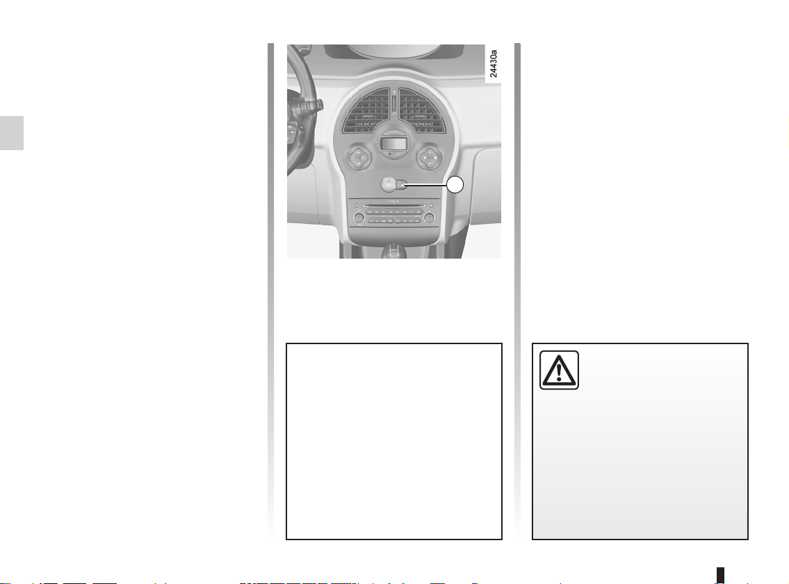
CHILD SAFETY: deactivating/activating the front passenger air bag (1/3)
1
2
Deactivating the front
passenger air bags
(on equipped vehicles)
You must deactivate the devices in addition to the front passenger seat belt
before fitting a child seat in the front
passenger seat.
1.38
To deactivate the air bags: when the
vehicle is stationary, push and turn
lock 1 to the OFF position.
With the ignition on, you must check
that indicator light 2
central display and, depending on the
vehicle, that the message “Passenger
air bag deactivated” is displayed.
This light remains permanently lit to
let you know that you can fit a child
seat.
] is lit on the
The passenger air bag must
only be deactivated or activated with the ignition off.
the vehicle is being driven, indicator
lights
on.
Switch the ignition off then on again
to reset the air bag in accordance
with the lock.
If it is interfered with when
å and © will come

CHILD SAFETY: deactivating/activating the front passenger air bag (2/3)
A
A
3
The markings on the dashboard and
labels A on each side of passenger sun
blind 3 (example: label shown above)
remind you of these instructions.
DANGER
Since operation of the front
passenger air bag is not
of a rear-facing child seat, NEVER
fit a rear-facing child seat on a front
passenger seat with an active front
air bag. The child may suffer very
serious injuries if the air bag is triggered.
compatible with the position
1.39

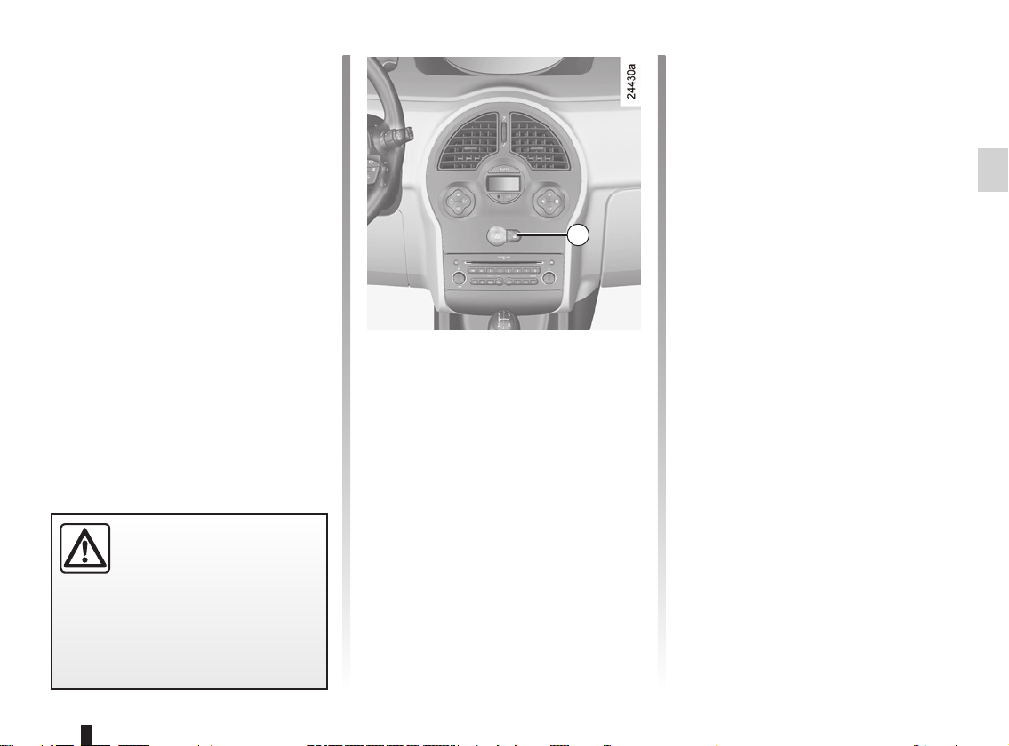
CHILD SAFETY: deactivating/activating the front passenger air bag (3/3)
DANGER
1
2
of a rear-facing child seat, NEVER
fit a rear-facing child seat on a front
passenger seat with an active front
air bag. The child may suffer very
serious injuries if the air bag is triggered.
Since operation of the front
passenger air bag is not
compatible with the position
Activating the front
passenger air bags
You should reactivate the air bag as
soon as you remove the child seat from
the front passenger seat to ensure the
protection of the front passenger in the
event of an impact.
To reactivate the air bags: switch off
the ignition, press and turn lock 1 to the
ON position.
With the ignition on, check that warning
] is off. The front passenger
light 2
seat belt additional restraint systems
are activated.
1.40
Operating faults
It is forbidden to fit a rear-facing child
seat to the front passenger seat if the
air bag activation/deactivation system
is faulty.
Allowing any other passenger to sit in
that seat is not recommended.
Contact your approved dealer as soon
as possible.
The passenger air bag must
only be deactivated or activated with the ignition off.
the vehicle is being driven, indicator
lights
on.
Switch the ignition off then on again
to reset the air bag in accordance
with the lock.
If it is interfered with when
å and © will come

STEERING WHEEL
1
Steering wheel height
adjustment
Pull lever 1 and place the steering
wheel in the required position; push the
lever to lock the steering wheel in place.
Make sure that the steering wheel is
correctly locked.
For safety reasons, only
adjust the steering wheel
when the vehicle is station-
ary.
Never leave the steering wheel on
full lock when the vehicle is stationary.
Do not drive with a low battery
charge. The steering wheel may not
operate correctly.
With the engine switched off, or if
there is a system fault, it is still possible to turn the steering wheel. The
force required will be greater.
A noise may be heard when the
steering wheel is moved quickly.
This is normal.
Never switch off the ignition when travelling downhill, and avoid doing so in
normal driving (assistance
is not provided).
1.41

DRIVER’S POSITION, LEFT-HAND DRIVE
1 2 3 5 6 7 8 9 10
4
26 23 22 21 20 19
14 13 12 11251824
1.42
17
15
16

DRIVER’S POSITION, LEFT-HAND DRIVE (continued)
The fittings described DEPEND ON THE VEHICLE VERSION AND COUNTRY.
1 Side window demister outlet.
2 Side air vent.
3 Stalk for:
– direction indicator lights;
– exterior lights;
– front fog lights;
– rear fog lights.
4 Driver’s air bag location, horn,
cruise control/speed limiter controls.
5 Stalk for:
– windscreen and rear screen
wash/wipe;
– Trip computer information read-
out control.
6 Ignition switch.
7 Instrument panel.
8 Passenger air bag location.
9 Side air vent.
10 Side window demister outlet.
11 Glove box.
12 Centre air vent.
13 Heating or air conditioning control.
14 Central door locking switch.
15 Gear lever.
16 Cigar lighter.
17 Handbrake.
18 Cruise control/speed limiter con-
trol.
19 Location for a cup holder, ashtray,
etc.
20 Location for radio, navigation
system, etc.
21 Hazard warning lights switch.
22 – Radio remote control;
– Hands-free telephone inte-
grated control.
23 Steering column height adjustment
control.
24 Bonnet release.
25 Fuse box.
26 Controls for:
– parking distance control;
– traction control;
– electric headlight beam adjust-
ment.
1.43

DRIVER’S POSITION, RIGHT-HAND DRIVE
1 2 3 5 9 10
26 25
24
23 11121314151617
7
84 6
22
1.44
21
20
18
19

DRIVER’S POSITION, RIGHT-HAND DRIVE (continued)
The fittings described DEPEND ON THE VEHICLE VERSION AND COUNTRY.
1 Side window demister outlet.
2 Side air vent.
3 Location of passenger air bag.
4 Centre air vents.
5 Instrument panel.
6 Stalk for:
– direction indicator lights;
– exterior lights;
– front fog lights;
– rear fog lights.
7 Driver’s air bag location, horn,
cruise control/speed limiter controls.
8 Stalk for:
– windscreen and rear screen
wash/wipe;
– Trip computer information read-
out control.
9 Side air vent.
10 Side window demister outlet.
11 Controls for:
– parking distance control;
– traction control;
– electric headlight beam adjust-
ment.
12 Ignition switch.
13 – Radio remote control.
– Hands-free telephone inte-
grated control.
14 Steering column height adjustment
control.
15 Heating or air conditioning control.
16 Central door locking switch.
17 Location for radio, navigation
system, etc.
18 Location for a cup holder, ashtray,
etc.
19 Cigar lighter.
20 Handbrake.
21 Cruise control/speed limiter con-
trol.
22 Gear lever.
23 Hazard warning lights switch.
24 Glove box.
25 Fuse box.
26 Bonnet release.
1.45

INSTRUMENT PANEL: warning lights (1/4)
The presence and operation of the warning lights DEPEND ON THE EQUIPMENT AND COUNTRY.
A
The instrument panel A lights up
when the ignition is switched on.
In some cases, the appearance of a
warning light is accompanied by a message.
The © warning light means
you should drive very carefully to
an approved dealer as soon as possible. If you fail to follow this recommendation, you risk damaging your
vehicle.
c
b
á
k
g
f
u
Left-hand direction indicator
tell-tale
Right-hand direction indicator tell-tale
Main beam headlight telltale
Dipped beam headlight telltale
Front fog light tell-tale
Rear fog light telltale
Side light tell-tale light
Door status warning light
2
Warning light ® requires you to stop immedi-
as soon as traffic conditions allow.
Switch off the engine and do not restart it. Contact an approved Dealer.
ately, for your own safety,
Ä
For vehicles equipped with this option,
the light comes on when the ignition is
switched on then goes out.
– If it lights up continuously, consult
– if it flashes, reduce the engine speed
Refer to the information on “Advice:
antipollution, fuel economy and driving”
in Section 2.
Toxic Fume Filter System
Warning Light
your approved dealer as soon as
possible;
until the light stops flashing. Contact
your approved Dealer as soon as
possible.
If no lights or sounds are apparent, this indicates a fault
in the instrument panel. This
indicates that it is essential
to stop immediately (as soon as traffic conditions allow). Ensure that the
vehicle is correctly immobilised and
contact an approved Dealer.
1.46

INSTRUMENT PANEL: warning lights (2/4)
The presence and operation of the warning lights DEPEND ON THE EQUIPMENT AND COUNTRY.
A
®
is switched on and goes out as soon as
the engine is started. It comes on with
other warning lights and/or messages,
and is accompanied by a beep.
It requires you to stop immediately, for
your own safety, as soon as traffic conditions allow. Switch off the engine and
do not restart it.
Contact an approved Dealer.
STOP light
This lights up when the ignition
À
tion is switched on and goes out after
a few seconds. If it comes on when you
are driving accompanied by the ®
warning light and a beep, it is essential
to stop and switch off the ignition.
Check the oil level. If the level is normal,
the indicator light is being lit by something else. Contact an approved Dealer.
Ú
is switched on and goes out after a few
seconds.
If it comes on when you are driving ac-
companied by the
and a beep, it indicates that the electrical circuit is overcharged or undercharged.
Stop as soon as traffic conditions allow
and contact an approved Dealer.
Oil pressure warning light
This lights up when the igni-
Battery charge warning light
This lights up when the ignition
® warning light
D
This comes on when the ignition is
switched on and goes out as soon as
the handbrake is released. If the handbrake is not fully released, the warning
light will remain lit, a beep will sound
and the message “handbrake on” will
be displayed on the instrument panel
when the vehicle reaches a speed of
12 mph (20 km/h) or more.
If it comes on during braking and is accompanied by the
and a beep, it indicates that the fluid
level in the circuit is low or that there is
a braking system fault. Stop as soon as
traffic conditions allow and contact an
approved Dealer.
Handbrake on and brake circuit incident warning light
® warning light
‰Š Fuel economy indicator lights
This lights up when the ignition is
switched on and goes out after a few
seconds. This lights up to let you know
the best time to engage a higher or
lower gear.
1.47

INSTRUMENT PANEL: warning lights (3/4)
The presence and operation of the warning lights DEPEND ON THE EQUIPMENT AND COUNTRY.
A
x
It comes on when the engine is started
then goes out.
If it lights up when you are driving, it indicates a fault in the anti-lock braking
system.
Braking will then be as normal, without
the ABS. Contact an approved Dealer
as soon as possible.
Anti-lock braking warning
light
å Air bag warning light
This lights up when the ignition is
switched on and goes out after a few
seconds.
If it does not light up when the ignition
is switched on, or comes on when the
engine is running, there is a fault in the
system. Contact your approved Dealer
as soon as possible.
è
c
A
ê
Automatic gearbox operational warning lights
Refer to information on
“Automatic gearbox” and
“Quickshift gearbox” in
Section 2.
Ü Particle filter warning light
Refer to the information on “Special
features of diesel versions with particle
filter” in Section 2.
ù
(ASR) warning light
There are several reasons for the warning light to come on: refer to the information on the “Electronic stability program: ESP" and "Traction control: ASR"
in Section 2.
©
is switched on and goes out as soon as
the engine is started. It can light up in
conjunction with other indicator lights
and/or messages on the instrument
panel.
It means you should drive very care-
fully to an approved dealer as soon as
possible. If you fail to follow this recommendation, you risk damaging your vehicle.
ê
Refer to the information on the “Engine
immobiliser” in Section 1.
Electronic stability program
(ESP) and traction control
Warning light
This lights up when the ignition
Engine immobiliser system
warning light
1.48

INSTRUMENT PANEL: warning lights (4/4)
The presence and operation of the warning lights DEPEND ON THE EQUIPMENT AND COUNTRY.
A
Φ
See the information on the “Speed limiter” and “Cruise control” in Section 2.
Speed limiter and cruise
control indicator lights
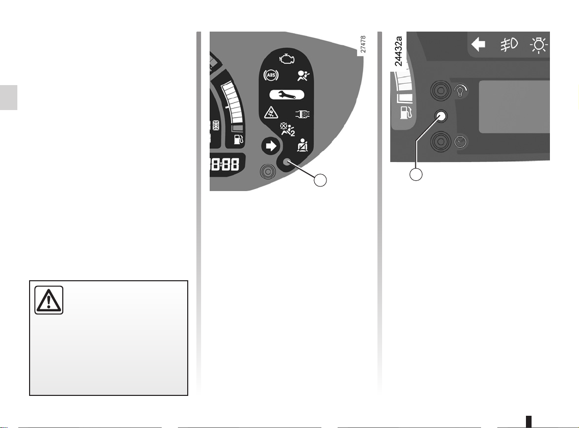
ç
If the driver’s seat belt is not fastened
it begins to flash when the vehicle
reaches a speed of 12 mph (20 km/h)
and a buzzer sounds for approximately
two minutes.
]
several seconds after the ignition is
switched on when the front passenger
air bags are deactivated (depending on
vehicle).
É
This should come on when the ignition is switched on. It indicates that the
heater plugs are in operation.
It goes out when preheating is complete. The engine can be started.
Driver’s seat belt reminder
warning light
Passenger air bag OFF
This warning light comes on
Preheating warning light
(diesel version)
1.49

INSTRUMENT PANEL: displays and indicators
1 1a
2 3 4 5 6 6a
7
Coolant temperature indicator 1
In normal use, the needle should be
below the area marked 1a. Under
severe conditions, the needle may
enter this area.
This is not serious unless the
warning light comes on, accompanied
by a message on the instrument panel
and a beep.
Gear engaged indicator 2 (for vehi-
cles with an automatic gearbox).
®
Rev counter 3
(scale x 1 000)
The red zone indicates a prohibited
engine speed
Speedometer 4 (mph or km/h)
Overspeed buzzer
Depending on the vehicle, a buzzer
sounds for approximately 10 seconds
every 40 seconds, as long as the vehicle is travelling in excess of 72 mph
(120 km/h).
Display 5
It lights up to indicate that a door or the
tailgate is open or not properly closed
(refer to the information on the “Tyre
pressure monitor” in Section 2).
Fuel gauge 6
The number of squares lit shows the
fuel level.
Minimum fuel level warning 6a
If it flashes and a beep sounds, this indicates that the minimum fuel level has
been reached. Fill up with fuel as soon
as soon as possible.
Each time the ignition is switched on
when the minimum fuel level has been
reached, a beep sounds to warn you.
Engine oil level low warning 7
The display informs the driver that the
engine oil level is low when the engine
is started. This warning lasts for 15 seconds. Refer to the information on the
“Engine oil level” in Section 4.
Trip computer and warning system
After 15 seconds, the display switches
to the trip computer function. Refer to
the information on the “Trip computer
and warning system” in the following
pages.
1.50

INSTRUMENT PANEL: displays and indicators (continued)
7
8
9
Instrument panel brightness
adjustment button 7
Refer to the information on “Exterior
lighting and signals” in Section 1.
Clock setting button 8
Refer to the information on the “Clock”
in Section 1.
9
Multifunction display 9
This displays several types of information: multimedia information, clock, external temperature.
1.51

TRIP COMPUTER: general information (1/2)
c) mileage before service,
d) programmed speed (speed limiter/
2
cruise control),
e) on-board log: operating fault and in-
formation message readout.
1
Trip computer and warning
system 1
Depending on the vehicle, this includes
the following functions:
– distance travelled;
– journey parameters;
– information messages;
– operating fault messages (con-
nected to the
– warning messages (connected to the
warning light
All these functions are described on the
following pages.
© warning light);
®).
3
Display selection keys 2
and 3
Scroll through the following information in this order or reverse the order by
briefly pressing the key repeatedly.
a) Total mileage and trip mileage re-
corder,
b) journey parameters:
– fuel used,
– average fuel consumption,
– current fuel consumption (de-
pending on vehicle),
– estimated range,
– distance travelled.
Instrument panel in miles
It is possible to switch to km/h.
With the ignition on, press either
button 2 or 3 and turn the key to the accessories position.
The speed measurement unit indicator flashes for approximately three seconds, then the new unit flashes on the
display and is then lit up continuously:
release button 2 or 3.
To return to the previous mode, repeat
the operation.
Note: once the battery is switched off,
the trip computer and warning system
automatically returns to the original unit
of measurement.
1.52

TRIP COMPUTER: general information (2/2)
2
3
Resetting the trip mileage
With the “trip mileage recorder” selected on the display, press and hold
button 2 or 3 until the mileage recorder
is reset.
Resetting the journey
parameters (reset button)
With one of the trip parameters selected
on the display, press button 2 or 3 until
the display is reset.
Interpreting some of the
values displayed after
resetting
The values showing average fuel consumption, range and average speed
will become more stable and reliable
the further you travel after pressing the
reset button.
For the first few miles after pressing the
reset button you may notice:
– that the range increases as you
travel.
This is normal, as average fuel consumption may decrease when:
– the vehicle stops accelerating;
– the engine reaches its operat-
ing temperature (if the engine
was cold when reset button was
pressed);
– when driving from a built-up area
onto the open road.
– You may also notice that the aver-
age fuel consumption increases
when the vehicle is stationary and
the engine idling.
This is normal, since the computer
takes account of fuel used during
idling.
Automatic resetting of the
journey parameters
Resetting occurs automatically when
the maximum value of any of the parameters is exceeded.
1.53

TRIP COMPUTER AND WARNING SYSTEM: journey parameters (1/4)
The display of information shown below DEPENDS ON THE VEHICLE EQUIPMENT AND COUNTRY.
Examples of selections Interpreting the display selected
a) Total mileage recorder
Trip mileage recorder
1.54
FUEL USED
AVERAGE
30.5L
5.3L/100
b) Journey parameters
Fuel consumed since the last reset.
Average fuel consumption since the last reset.
This value is displayed after driving 400 metres and takes into account the
distance travelled and the fuel used since the last time the reset button was
pressed.

TRIP COMPUTER AND WARNING SYSTEM: trip parameters (2/4)
The display of information shown below DEPENDS ON THE VEHICLE EQUIPMENT AND COUNTRY.
Examples of selections Interpreting the display selected
CURRENT
TRIP
AVERAGE
12.3L/100
275.5KM
82KM/H
Current fuel consumption
This value is displayed after a speed of approximately 18 mph (30 km/h) is
reached.
Estimated range with remaining fuel
This range takes into account the average fuel consumption since the last
time the reset button was pressed.
The value is displayed after driving 400 metres.
Several minutes after the reserve light has come on (refer to the information
on the “Instrument panel”), the estimated range will no longer be displayed.
Distance travelled since the last reset.
Average speed since the last reset.
1.55

TRIP COMPUTER AND WARNING SYSTEM: trip parameters (3/4)
The display of information shown below DEPENDS ON THE VEHICLE EQUIPMENT AND COUNTRY.
Examples of selections Interpreting the display selected
c) Mileage before service
Distance remaining until the next service (displayed in miles (kilometres)
and months), then when the service nears, several scenarios are pos-
Ê
NB: depending on the vehicle, the mileage before service changes according to the driving style (frequent driving at low speed,
door-to-door journeys, extensive use at idle speed, towing a trailer etc.). The distance remaining until the next service can therefore decrease more quickly in some cases than the actual distance travelled.
The service intervals are independent of the vehicle’s maintenance schedule: please refer to your vehicle’s Maintenance Service
Booklet.
Resetting: to reset the distance before service with the display selecting “service”, press and hold one of the display reset buttons for approximately 10 seconds until the display shows the mileage permanently.
SERVICE DUE IN
25360KM
sible:
– distance/time remaining less than 900 miles (1,500 km) or one
month: the message “SERVICE DUE IN” is displayed;
– distance equal to 0 miles/km or service date reached: the message
“SERVICE DUE” is displayed when the selected display is “mileage
before service”, accompanied by the
ing light.
The vehicle requires a service as soon as possible.
Ê symbol and the © warn-
1.56

TRIP COMPUTER AND WARNING SYSTEM: trip parameters (4/4)
The display of information shown below DEPENDS ON THE VEHICLE EQUIPMENT AND COUNTRY.
Examples of selections Interpreting the display selected
CRUISE
CONTROL
90KM/H
SPEED LIMITER
90KM/H
d) Cruise control/speed limiter speed setting (depending on vehicle)
Refer to the information on the “Cruise control - Speed limiter” in Section 2.
AUTO LIGHTS DE-
ACTIVATED
e) On-board log
Successive display:
– information messages (depending on the vehicle: automatic headlights,
etc.),
– operating fault messages (check the injection system, etc.).
1.57

TRIP COMPUTER AND WARNING SYSTEM: information messages
These can help in the vehicle starting phase, or give information about a selection or a driving status.
Examples of information messages are given in the following pages.
Examples of messages Interpreting the display selected
“BOOT OPEN” Indicates that the tailgate has been left open.
“OIL LEVEL OK” Indicates that the oil level is correct when the ignition is switched on.
“ A U T O L I G H T S DE ACTIVATED”
1.58
Indicates that the automatic lights function is deactivated.

TRIP COMPUTER AND WARNING SYSTEM: operating fault messages
These appear with the
as possible. If you fail to follow this recommendation, you risk damaging your vehicle.
They disappear when the display selection key is pressed or after several seconds and are stored in the computer log. The
warning light stays on. Examples of operating fault messages are given in the following pages.
Examples of messages Interpreting the display selected
“CHECK ESP SYSTEM”
“CHECK FUEL FILTER”
“CHECK GEARBOX”
“CHECK AUTO LIGHTS” Indicates an automatic lights operating fault; contact your approved Dealer.
“CHECK STEERING” Indicates a power-assisted steering system operating fault.
© warning light and mean that you should drive very carefully to an authorised dealer as soon
Indicates a fault in the traction control system (refer to Section 2: “Traction control: ASR").
Indicates that there is water present in the diesel fuel.
Contact your approved Dealer as soon as possible.
Indicates that a fault has occurred in the gearbox; contact your approved Dealer
as soon as possible.
©
1.59

TRIP COMPUTER AND WARNING SYSTEM : warning messages
These appear with the
conditions allow. Stop your engine and do not restart it. Contact an approved Dealer.
Examples of warning messages are given in the following pages. Note: the messages appear on the display either individually
or alternately (when there are several messages to be displayed), and may be accompanied by a warning light and/or a beep.
Examples of messages Interpreting the display selected
“INJECTION FAULT” Indicates that the vehicle has a serious engine fault.
“ENGINE OVERHEATING” Indicates that the engine is overheating.
“CHECK STEERING” Indicates a fault in the vehicle’s power-assisted steering.
“GEARBOX OVERHEATING” Indicates that the gearbox is overheating.
® warning light and require you to stop immediately, for your own safety, as soon as traffic
1.60

INFORMATION DISPLAYS
A
B C
1
Depending on the vehicle, displays 1
or 2 may show:
– the external temperature (zone A);
– the radio (zone B);
– the time (zone C);
– navigation aid information (zone D).
B
C
A
D
2
If the electrical supply is cut (battery
disconnected, broken supply wire,
etc.), the clock will lose its time setting.
The clock must be reset.
We recommend that you do not
adjust these settings while driving.
1.61

CLOCK
2
1
The time is displayed when the ignition
is switched on.
1.62
1
2
Resetting the clock 1
– press button 2 for approximately
three seconds to enter time setting
mode;
– when the hour flashes, press
button 2 again to adjust it;
– wait approximately three seconds,
the minutes will flash; press button 2
to set the minutes;
– wait approximately three seconds,
the minutes will stop flashing; the
time is set.
If the electrical supply is cut (battery
disconnected, broken supply wire,
etc.), the clock will lose its time setting.
The clock must be reset.
We recommend that you do not
adjust these settings while driving.

EXTERNAL TEMPERATURE
1
External temperature
indicator 1
The external temperature is displayed
when the ignition is switched on.
1
Special note:
When the outside temperature is – 3 °C
to + 3° C, the °C characters flash (signalling a risk of black ice on the road).
External temperature
indicator
As ice formation is related
to exposure, local air humidity and temperature, the external
temperature alone is not sufficient to
indicate the presence of ice.
1.63

DOOR MIRRORS (1/2)
A
B
1
Door mirrors with manual
adjustment
To adjust the mirror, move lever 1.
The driver’s door mirror
may have two clearly de-
fined zones. Zone B shows
what can normally be seen
in an ordinary rear view mirror. For
your safety, zone A increases the
area you can see at the rear and to
the side of your vehicle.
The objects in zone A look much
further away than they really are.
1.64

DOOR MIRRORS (2/2)
A
B
D
Folding door mirrors
Move button 2 to position F and the
door mirrors fold in.
To reset them for driving, return to position C, D or E.
C
F
E
2
Electric door mirrors
With the ignition on, move button 2:
– position C to adjust the left-hand
door mirror;
– position E to adjust the right-hand
door mirror;
D is the inactive position.
Heated door mirrors
With the engine running, mirror de-
icing is activated simultaneously with
rear screen de-icing/demisting.
The driver’s door mirror
may have two clearly de-
fined zones. Zone B shows
what can normally be seen
in an ordinary rear view mirror. For
your safety, zone A increases the
area you can see at the rear and to
the side of your vehicle.
The objects in zone A look much
further away than they really are.
3
Interior rear view mirror
Its position can be adjusted. When driving at night, to avoid being dazzled by
the headlights of the vehicle behind,
depress the little lever located behind
the rear view mirror 3.
1.65

AUDIBLE AND VISUAL SIGNALS
1
0
A
Horn
Press steering wheel boss A.
Headlight flasher
To flash the headlights, even if the lights
are not on, pull stalk 1 towards you.
2
Direction indicators
Move stalk 1 parallel to the steering
wheel and in the direction you are going
to turn it.
When driving on the motorway, the
steering wheel is not often turned
enough to return the stalk automatically
to 0. There is an intermediate position
in which the stalk may be held when
changing lanes.
When the stalk is released, it automatically returns to 0.
é
tivates all four direction indicators and
the side indicator lights simultaneously.
It must only be used in an emergency to
warn drivers of other vehicles that you
have had to stop in an area where stopping is prohibited or unexpected or that
you are obliged to drive under special
conditions.
Depending on the vehicle, the hazard
warning lights may come on automatically under heavy deceleration. You can
switch them off by pressing switch 2.
Press switch 2. This switch ac-
Hazard warning lights
1.66

EXTERIOR LIGHTING AND SIGNALS (1/5)
1
Switching on the side
u
Turn the end of stalk 1 until the symbol
is opposite mark 2.
In all cases, an indicator light on the instrument panel comes on.
lights
1
2
Before driving at night,
check that the electrical
equipment is operating cor-
rectly and adjust the headlight beams (if your vehicle is not
carrying its normal load). In general, check that the lights are not
obscured (by dirt, mud, snow or objects which could cover them).
3
3
Adjusting the brightness of
the instrument panel lighting
With the lights on, press button 3. Each
time the button is pressed, the brightness increases; there are four levels of
brightness. Pressing the button again
will dim the lighting to its lowest level.
1.67

EXTERIOR LIGHTING AND SIGNALS (2/5)
1
2
4
Switching on dipped
k
Manual operation
Turn the end of stalk 1 until the symbol
is opposite mark 2.
In all cases, an indicator light on the instrument panel comes on.
beam headlights
Automatic operation (depending on
vehicle)
With the engine running, the dipped
beam headlights are switched on or off
automatically depending on the level of
ambient light, without the need to operate stalk 1 (position 0).
This function can be deactivated or reactivated.
– To activate it, with the ignition on,
press button 4 for at least four seconds. An instrument panel message
confirms this action.
– To deactivate it, with the ignition on,
press button 4 for at least four seconds. The “Auto lights OFF” message is displayed on the instrument
panel.
If stalk 1 is operated, it overrides and
cancels the automatic function temporarily.
See-me-home lighting
function
This function (useful, for example, for
opening a gate, a garage, etc.) enables
you to switch on dipped headlights momentarily.
With the ignition off and the headlights
off, pull stalk 1 towards you: the dipped
beam headlights come on for approximately thirty seconds.
This action may be carried out no more
than four times for a maximum lighting
period of two minutes.
To switch off the lights before they
go out automatically, turn the end of
stalk 1, then return it to position 0.
1.68

EXTERIOR LIGHTING AND SIGNALS (3/5)
Cornering lights
Depending on the vehicle, if the dipped
beam headlights are on when cornering, and under certain driving conditions (speed, steering wheel angle, forwards gear selected, etc.), additional
lights are switched on to light the inside
of the bend.
Note: under certain conditions of prolonged use, this system will be switched
off automatically as it is intended for
use over limited periods.
1
Switching on the main
á
With the dipped beam headlights lit,
pull stalk 1 towards you.
When the main beam headlights are
lit, an indicator light on the instrument
panel comes on.
To return to the dipped headlight position, pull stalk 1 towards you.
beam headlights
Automatic lighting with main
beam headlights
Depending on the vehicle, when you
change to main beam headlights, the
dipped beam headlight raise to improve
lighting.
Note: in the event of an operating fault
on the system, the dipped beam headlight and the main beam headlight concerned go out and the front fog lights
come on accompanied by the
strument panel warning light.
Warning: as this operating mode is not
a normal driving condition, consult an
approved dealer as soon as possible.
g in-
1.69

EXTERIOR LIGHTING AND SIGNALS (4/5)
1
Switching off the lights
Manual operation
There are three options (depending on
the vehicle):
– return stalk 1 to its initial position;
– the lights extinguish when the engine
is stopped, when the driver’s door
is opened or when the vehicle is
locked. In this case, the next time
the engine is started the lights will be
switched back according to the position of the stalk 1;
– a timer will switch off the lights auto-
matically.
Automatic operation (depending on
vehicle)
The lights go out when the engine
is stopped, when the driver’s door is
opened or when the vehicle is locked.
Lights-on warning buzzer
If the lights are switched on after the
engine is switched off, a warning
beep sounds when the driver’s door is
opened to warn you that the lights are
still on.
1.70

EXTERIOR LIGHTING AND SIGNALS (5/5)
5
1
6
Front fog lights
g
until the symbol faces mark 6, then release it.
Operation of the fog lights depends on
the exterior lighting selected, and an indicator light will light up on the instrument panel.
Do not forget to switch off the fog lights
when they are no longer needed, to
avoid inconveniencing other road
users.
Turn centre ring 5 on stalk 1
f
until the symbol faces mark 6, then release it.
The fog light can only be switched on if
the dipped beam headlights or front fog
lights are lit.
To avoid inconveniencing other road
users, remember to switch off the rear
fog light when it is no longer needed.
Note: the fog light is located on the
driver’s side.
Turn centre ring 5 on stalk 1
Erratic illumination of the front fog
light indicator light on the instrument
panel indicates an operating fault
with the automatic lighting of the
main beam headlights.
Refer to the information on
“Automatic lighting with main beam
headlights” in Section 1.
Rear fog light
Switching off the lights
Turn ring 5 again until mark 6 is opposite the symbol for the fog light you wish
to switch off.
The front and rear fog lights switch off
when the exterior lights are switched
off.
When driving in the fog, the dipped
beam headlights do not come on
automatically, you must switch them
on manually.
Switching on the fog lights remains
the responsibility of the driver: the
indicator lights on the instrument
panel inform you whether the fog
lights are lit (indicator light on) or not
(indicator light not on).
1.71

ELECTRIC BEAM HEIGHT ADJUSTMENT
Examples of positions for control
Driver only 0
A depending on the load
A
On vehicles fitted with this function,
control A allows you to adjust the height
of the beams according to the load.
Turn control A downwards to lower the
headlights and upwards to raise them.
1.72
Driver with one front
passenger
Driver with one front
passenger and three
rear passengers
Driver with one front
passenger, three
rear passengers and
luggage
Driver with luggage
or load reaching the
maximum permissible
all-up weight
0
1
2
3

WINDSCREEN WASH/WIPE (1/2)
D
With the ignition on, move stalk 1
A park
B intermittent wiping
The wipers will pause for several
seconds between sweeps. It is possible to change the time between
sweeps by turning ring 2.
C normal wiping speed
D fast wiping speed
1
1
2
A
B
C
Special note
When the vehicle is being driven, the
wiping speed slows down whenever the
vehicle stops. The speed will change
from fast wiping speed to normal wiping
speed.
As soon as the vehicle moves off,
wiping will return to the speed originally
selected.
Any action on stalk 1 overrides and
cancels automatic operation.
Vehicles with automatic wiper
function
With the engine running, move stalk 1
A park
B automatic wiper function
When this position is selected, the
system detects the presence of
water on the windscreen and triggers
wiping at a suitable wiping speed.
It is possible to modify the sensitivity
by turning ring 2.
Each time the engine is started, it
is essential to return to park position A then to return to the automatic wiping position.
C normal wiping speed
D fast wiping speed
When working in the engine compartment, ensure that the windscreen
wiper stalk is in position A (park).
Risk of injury.
With the vehicle stationary, if for
any reason the wipers cannot move
(e.g. stuck to windscreen by ice),
the system will automatically cut off
the power supply to the wipers.
1.73

WINDSCREEN WASH/WIPE (2/2)
1
A
B
C
D
Headlights on
The headlight washers will be activated
at the same time.
Windscreen washers,
headlight washers
(depending on vehicle)
With the ignition on, pull stalk 1 to-
wards you.
Headlights off
A short press triggers one sweep cycle
of the wiper.
A longer press triggers three sweeps
followed by a final sweep after several
seconds.
1.74
In frosty weather, make sure that
the wiper blades are not stuck by ice
(risk of motor overheating).
Keep an eye on the condition of the
blades. Replace the wiper blades as
soon as they begin to lose efficiency
(approximately once a year).
Clean your windscreen regularly.
If you switch off the ignition before
switching off the windscreen wiper
(position A) the blades will stop at
random on the windscreen.
Before any action on the
windscreen (washing the
vehicle, de-icing, cleaning
the windscreen, etc.) return
stalk 1 to position A (park).
Risk of injury and/or damage.
When working in the engine
compartment, ensure that
the windscreen wiper stalk
is in position A (park).
Risk of injury.

REAR SCREEN WASH/WIPE
1
2
Speed-dependent rear
Y
screen wiper with
timer
With the ignition on, turn the end of
stalk 1 to align mark 2 with the symbol.
Wiping frequency varies with speed.
When working in the engine
compartment, ensure that
the windscreen wiper stalk
is in the park position.
Risk of injury.
p
end of stalk 1 to align mark 2 with the
symbol.
When the stalk is released, it returns to
the rear screen wiper position.
With the ignition on, turn the
Special note
If the windscreen wipers are operating or are in automatic mode, the rear
screen wiper wipes intermittently when
reverse gear is engaged.
Before any action on the
windscreen (washing the
vehicle, de-icing, cleaning
Rear screen wash/wipe
stalk 1 to the park position.
Risk of injury or damage.
the windscreen, etc.) return
In freezing or snowy weather, ensure
they are not stuck to the windscreen
(including the central area located
behind the interior rear-view mirror)
and the rear screen before starting
the wipers (risk of motor overheating).
Check the condition of the wiper
blades. You are responsible for their
service life:
– they must remain clean: clean
the blades, windscreen and
rear screen regularly with soapy
water;
– do not use them when the wind-
screen or rear screen are dry;
– free them from the windscreen or
rear screen when they have not
been used for a long time.
In all cases, replace them as soon
as they begin to lose efficiency: approximately once a year.
Before using the rear wiper, check
that no object obstructs the travel of
the blade.
Do not use the wiper arm to open or
close the tailgate.
1.75
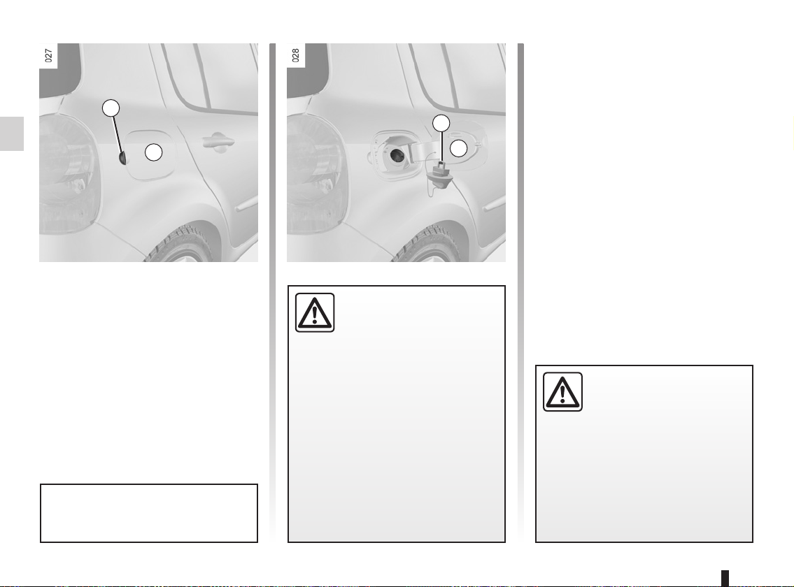
FUEL TANK (1/2)
1
A
Capacity of the fuel tank: 49 litres ap-
proximately.
To open the compartment A, place your
finger into the recess 1, then pull the
cover.
For details on filling the fuel tank, refer
to the information on “Filling with fuel”
on the next page.
Cap holder 2 is provided on the fuel
filler flap for holding the cap when the
tank is being filled.
After filling, check that the cap and
cover are closed.
2
A
Fuel filler cap: this is of a
special type.
If you have to replace it,
make sure it is identical
to the original cap. Contact an approved Dealer.
Never place the cap near a source
of heat or flame.
Do not wash the filler area with a
high-pressure washer.
Fuel grade
Use a high grade fuel that complies
with the standards currently in force in
each country.
Diesel version
It is essential to use diesel fuel that
conforms with the information given on
the label inside cover A.
Make sure that no water accidentally
enters the fuel tank during filling. The
shut-off system and its surrounding
area must be dust-free.
Do not mix even small
amounts of petrol (unleaded or E85) with diesel.
Do not use ethanol-based
fuel if your vehicle is not compatible
with this fuel.
Do not add any additives to the fuel,
you risk damaging the engine.
1.76

FUEL TANK (2/2)
Petrol version
It is essential to use unleaded petrol.
The octane rating (RON) must conform with the specifications given on
the label inside fuel filler flap A. Refer
to the information on “Engine specifications” in Section 6.
Special features of vehicles running
on ethanol-based fuel:
It is essential to use unleaded petrol or
fuel containing a maximum of 85% ethanol (E85).
To make it easier to start the engine in
very cold conditions, it is recommended
to use unleaded petrol or, on equipped
vehicles, to use the heater integrated in
the engine.
In this case, connect the special end of
the extension piece supplied into the
socket integrated into the radiator grille
and the other end into a 220V socket
for at least 6 hours before starting.
Note: when using ethanol-based fuel,
you may notice over-consumption.
Filling up with fuel
Petrol versions
Using leaded petrol will damage the
antipollution system and may lead to a
loss of warranty.
To ensure the fuel tank is not filled
with leaded petrol, the fuel tank filler
neck contains a restrictor fitted with a
foolproof system which only allows
the nozzle for unleaded petrol to be
used (at the pump):
– Insert the nozzle so that the valve
is pushed back and fully insert it
before beginning to fill the fuel tank,
(risk of splash-back);
– Keep the nozzle in this position
throughout the entire filling operation.
Petrol and diesel versions
When the pump cuts out automatically
at the end of the filling procedure, a
maximum of two further filling attempts
may be made, as there must be sufficient space in the fuel tank to allow for
expansion.
Persistent smell of
fuel
If you notice a persistent
smell of fuel you should:
– stop the vehicle as soon as traf-
fic conditions allow and switch off
the ignition;
– switch on the hazard warning
lights and ask your passengers
to leave the vehicle and to keep
away from traffic;
– contact an approved Dealer.
No modifications what-
soever are permitted on
any part of the fuel supply
system (computers, wiring,
fuel circuit, injector, protection
covers, etc.) as this may be dangerous (such work must be undertaken
by qualified Network personnel).
1.77

1.78

Section 2: Driving
(Advice on use relating to fuel economy and the environment)
Running in . . . . . . . . . . . . . . . . . . . . . . . . . . . . . . . . . . . . . . . . . . . . . . . . . . . . . . . . . . . . . . . . . . . . . 2.2
Ignition switch . . . . . . . . . . . . . . . . . . . . . . . . . . . . . . . . . . . . . . . . . . . . . . . . . . . . . . . . . . . . . . . . . . 2.3
Starting/stopping the engine . . . . . . . . . . . . . . . . . . . . . . . . . . . . . . . . . . . . . . . . . . . . . . . . . . . . . . . 2.4
Special features of petrol versions . . . . . . . . . . . . . . . . . . . . . . . . . . . . . . . . . . . . . . . . . . . . . . . . . . 2.5
Special features of diesel versions . . . . . . . . . . . . . . . . . . . . . . . . . . . . . . . . . . . . . . . . . . . . . . . . . . 2.6
Special features of diesel versions fitted with a particle filter . . . . . . . . . . . . . . . . . . . . . . . . . . . . . . 2.7
Gear lever/Power-assisted steering . . . . . . . . . . . . . . . . . . . . . . . . . . . . . . . . . . . . . . . . . . . . . . . . . 2.8
Handbrake . . . . . . . . . . . . . . . . . . . . . . . . . . . . . . . . . . . . . . . . . . . . . . . . . . . . . . . . . . . . . . . . . . . . . 2.9
Advice on emission control, fuel economy and driving . . . . . . . . . . . . . . . . . . . . . . . . . . . . . . . . . . . 2.10
Environment . . . . . . . . . . . . . . . . . . . . . . . . . . . . . . . . . . . . . . . . . . . . . . . . . . . . . . . . . . . . . . . . . . . 2.13
Anti-lock braking system: ABS. . . . . . . . . . . . . . . . . . . . . . . . . . . . . . . . . . . . . . . . . . . . . . . . . . . . . . 2.14
Electronic Stability Programme: ESP . . . . . . . . . . . . . . . . . . . . . . . . . . . . . . . . . . . . . . . . . . . . . . . . 2.15
Traction control: ASR . . . . . . . . . . . . . . . . . . . . . . . . . . . . . . . . . . . . . . . . . . . . . . . . . . . . . . . . . . . . . 2.17
Emergency brake assist . . . . . . . . . . . . . . . . . . . . . . . . . . . . . . . . . . . . . . . . . . . . . . . . . . . . . . . . . . 2.19
Speed limiter . . . . . . . . . . . . . . . . . . . . . . . . . . . . . . . . . . . . . . . . . . . . . . . . . . . . . . . . . . . . . . . . . . . 2.20
Cruise control . . . . . . . . . . . . . . . . . . . . . . . . . . . . . . . . . . . . . . . . . . . . . . . . . . . . . . . . . . . . . . . . . . 2.23
Automatic gearbox. . . . . . . . . . . . . . . . . . . . . . . . . . . . . . . . . . . . . . . . . . . . . . . . . . . . . . . . . . . . . . . 2.27
Quickshift gearbox . . . . . . . . . . . . . . . . . . . . . . . . . . . . . . . . . . . . . . . . . . . . . . . . . . . . . . . . . . . . . . . 2.31
Parking distance control . . . . . . . . . . . . . . . . . . . . . . . . . . . . . . . . . . . . . . . . . . . . . . . . . . . . . . . . . . 2.36
2.1

RUNNING IN
Petrol version
For the first 600 miles (1,000 km), do
not exceed 78 mph (130 km/h) in the
highest gear, or 3,000 to 3,500 rpm.
You may only expect top performance
from your vehicle after approximately
1,800 miles (3,000 km).
Service intervals: refer to the
Maintenance Service Booklet for your
vehicle.
Diesel version
For the first 900 miles (1,500 km),
do not exceed 2,500 rpm. After completing this mileage you may drive
faster, although you may only expect
top performance after approximately
3,600 miles (6,000 km).
During the running in period, do not accelerate hard while the engine is still
cold and do not let the engine over-rev.
Service intervals: refer to the
Maintenance Service Booklet for your
vehicle.
2.2

IGNITION SWITCH
Position S: Off and steering
lock applied
To lock: remove the key and turn the
steering wheel until the steering column
locks.
To unlock: turn the key and the steering
wheel slightly.
Accessories position A
When the ignition is switched off, any
accessories (radio, etc.) will continue to
function.
Ignition on position M
The ignition is switched on.
Start position D
If the engine fails to start at the first
attempt, the key must be turned back
before the starter can be activated
again. Release the key as soon as the
engine starts.
Note: on diesel versions, several seconds may pass between turning the
key and the engine starting to allow for
engine preheating.
Starting a vehicle with automatic
gearbox
Before starting, move the lever to position N or P.
2.3

STARTING/STOPPING THE ENGINE
Starting the engine
Petrol injection
Engine warm or cold
–
Turn the key to the start position
without depressing the accelerator.
– Release the key as soon as the
engine starts.
É
Cold or warm engine
–
– Release the key as soon as the
Note: several seconds may pass between turning the key and the engine
starting to allow for engine preheating.
Diesel injection
Turn the key to “Start” position D
without depressing the accelerator.
engine starts.
When you leave your vehicle, check that the engine
has completely stopped.
Stopping the engine
With the engine idling, turn the key
back to the Stop position.
Never leave your vehicle
with the key inside the vehi-
cle and never leave a child
(or a pet) unsupervised,
even for a short while.
There is a risk that they could start
the engine or operate electrical
equipment (electric windows etc.)
and trap part of their body (neck,
arms, hands, etc.).
Risk of serious injury.
Never switch off the ignition before
the vehicle has stopped completely.
Once the engine has stopped, the
brake servo, power-assisted steering, etc. and the passive safety devices such as air bags and pretensioners will no longer operate.
2.4

SPECIAL FEATURES OF PETROL VERSIONS
The following operating conditions:
– driving for long periods when the low
fuel level warning light is lit;
– using leaded petrol;
– using fuel or lubrication additives
which are not approved.
Or operating faults such as:
– faulty ignition system, running out of
fuel or disconnected spark plugs re-
sulting in the engine misfiring or cut-
ting out when driving;
– loss of power,
as they may cause the catalytic con-
verter to overheat and thus reduce its
efficiency, or damage it irreparably
and cause heat damage to the vehicle.
If you notice any of the above operating
faults, have the necessary repairs carried out as soon as possible by an approved Dealer.
These faults may be avoided by regularly taking your vehicle to an approved
Dealer at the intervals specified in the
Maintenance Service Booklet.
Starting problems
To avoid damaging the catalytic converter, do not keep trying to start the
engine (using the start button, or by
pushing or towing the vehicle) without
having identified and corrected the
starting fault.
If the fault cannot be identified, do not
keep trying to start the engine, but contact an approved Dealer.
Do not park the vehicle or
run the engine in locations
where combustible sub-
stances or materials such
as grass or leaves can come into
contact with the hot exhaust system.
2.5

SPECIAL FEATURES OF DIESEL VERSIONS
Diesel engine speed
Diesel engines are fitted with injection
equipment which prevents the engine
speed being exceeded irrespective of
the gear selected.
When driving, depending on the fuel
grade used, it is possible that white
smoke may be emitted.
This is due to the exhaust particle filter
being cleaned automatically, and does
not affect the way the vehicle runs.
Running out of fuel
You may start the engine normally after
refilling the fuel tank even if you have
completely run out of fuel, provided
that the battery is well-charged.
However, if the engine fails to start after
a few seconds and several attempts,
contact an approved dealer.
Precautions to be taken in
winter
To avoid faults in icy weather:
– ensure that the battery is always fully
charged,
– always keep the diesel tank rela-
tively full to avoid water vapour condensing in it and accumulating at the
bottom of the tank.
Do not park the vehicle or
run the engine in locations
where combustible sub-
stances or materials such
as grass or leaves can come into
contact with the hot exhaust system.
2.6

SPECIAL FEATURES OF DIESEL VERSIONS FITTED WITH A PARTICLE FILTER
Depending on the vehicle, the Ü
warning light comes on to indicate a
filter saturation risk.
Within 60 miles (100 km) of the message appearing, drive at an average
speed of 24 mph (40 km/h), as traffic
conditions and speed limits allow, until
the warning light goes out. If the vehicle
is stopped before the message disappears you will have to restart the process from the beginning.
As a guide, this type of cleaning should
take up to 20 minutes.
If the message “Check antipollution” is displayed on the instrument
panel accompanied by the
© and
Üwarning lights; consult an ap-
proved dealer straight away.
Do not park the vehicle or
run the engine in locations
where combustible sub-
as grass or leaves can come into
contact with the hot exhaust system.
stances or materials such
When driving, depending on the fuel
grade used, it is possible that white
smoke may be emitted.
This is due to the exhaust particle filter
being cleaned automatically, and does
not affect the way the vehicle runs.
Diesel engine speed
Diesel engines are fitted with injection
equipment which prevents the engine
speed being exceeded irrespective of
the gear selected.
2.7

GEAR LEVER/POWER-ASSISTED STEERING
1
Selecting reverse gear
Vehicles with manual gearbox: refer
to the grid on the gear lever knob 1.
Vehicles with an automatic gearbox: refer to the information on the
“Automatic gearbox” in Section 2.
The reversing lights will come on as
soon as reverse gear is selected with
the ignition on.
in damage to the vehicle (e.g.: deformation of an axle).
To avoid any risk of accident, have
your vehicle checked by an approved Dealer.
An impact to the underside
of the vehicle (e.g.: striking
a post, raised kerb or other
street furniture) may result
Power Assisted Steering
Never drive with an inadequately
charged battery.
Variable power assisted
steering
The variable power assisted steering
system is equipped with an electronic
control system which alters the level of
assistance to suit the vehicle speed.
Steering is made easier during parking
manoeuvres (for added comfort) whilst
the force needed to steer increases
progressively as the speed rises (for
enhanced safety at high speeds).
Never leave the steering wheel on
full lock when the vehicle is stationary.
Never switch off the igni-
tion when travelling down-
hill, and avoid doing so in
normal driving (assistance
is not provided).
2.8

HANDBRAKE
2
1
To release
Pull lever 1 up slightly, press button 2
and then lower the lever to the floor.
The red warning light on the instrument
panel will stay on if you are driving with
the handbrake not fully released.
Make sure that the handbrake is properly released
when driving (red indicator
light off), otherwise overheating, or even damage, may
occur.
To apply
Pull upwards. Check that the vehicle is
immobilised.
When stationary and depending on the slope and/or
vehicle load, it may be nec-
brake at least two extra notches and
engage a gear (1
for vehicles with a manual gearbox
or position P for vehicles with an automatic gearbox.
essary to pull up the hand-
st
or reverse gear)
2.9

ADVICE: antipollution, fuel economy and driving (1/3)
By virtue of its design, moderate fuel
consumption and initial settings, your
vehicle conforms to current antipollution regulations. The manufacturer
is actively striving to reduce pollutant
exhaust gas emissions and to save
energy. But the fuel consumption of
your vehicle and the level of pollutant
exhaust gas emissions are also your
responsibility. Ensure that it is maintained and used correctly.
Aiding fuel economy
Depending on the vehicle, in order to
optimise consumption, the trip computer and warning system will inform you
of the best moment to upshift or downshift gears:
Š upshift a gear;
‰ shift down a gear.
Maintenance
It is important to remember that failure to
respect antipollution regulations could
lead to legal action being taken against
the vehicle owner. In addition, replacing
engine, fuel supply system and exhaust
components with parts other than those
originally recommended by the manufacturer may alter your vehicle so that
it no longer complies with antipollution
regulations.
Have your vehicle adjusted and
checked by an approved dealer, in accordance with the instructions given in
your maintenance schedule: they will
have all the equipment necessary for
ensuring that your vehicle is maintained
to its original standard..
Engine adjustments
– ignition: this does not require ad-
justment.
– spark plugs: for optimum fuel econ-
omy, efficiency and performance
the specifications laid down by our
Design Department must be strictly
applied.
If the spark plugs have to be
changed, use the make, type and
gap specified for your vehicle’s
engine. Contact an approved dealer
for this.
– idling speed: this does not require
adjustment.
– air filter, diesel filter: a clogged el-
ement hinders performance. It must
be replaced.
2.10

ADVICE: antipollution, fuel economy and driving (2/3)
Exhaust gas monitoring
system
The exhaust gas monitoring system will
detect any operating faults in the vehicle’s antipollution system.
If this system malfunctions, toxic substances may be released into the atmosphere or damage may occur.
Ä
there are any faults in the system:
This lights up when the ignition is
switched on and goes out when the
engine is started.
– If it lights up continuously, consult an
– if it flashes, reduce the engine speed
This warning light on the instrument panel will indicate if
approved Dealer as soon as possible;
until the light stops flashing. Contact
your approved dealer as soon as
possible.
Driving
– Drive carefully for the first few miles
until the engine reaches its normal
operating temperature, rather than
let it warm up while the vehicle is sta-
tionary.
– Speed is expensive.
– Do not overrev the engine in the in-
termediate gears.
Always use the highest gear possi-
ble without labouring the engine.
On versions with an automatic gear-
box, it is preferable to keep the gear
lever in position D.
– Avoid sudden acceleration.
– Sporty driving uses a lot of fuel: drive
with a light right foot.
– Brake as little as possible. If you an-
ticipate an obstacle or bend in advance, you may then simply release
the accelerator pedal.
– Do not try to maintain the same
speed up a hill, accelerate no more
than you would on the level. Keep
your foot in the same position on the
accelerator pedal.
– Double declutching and accelerating
before switching off are unnecessary
in modern vehicles.
– Bad weather, flooded roads
Do not drive through floods
if the water is above the
lower edge of the wheel
rims.
Obstructions to the driver
On the driver’s side, only
use mats adapted to the ve-
hicle that attach to the preinstalled parts, and regularly check
their mounting. Do not place several
mats on top of each other.
Risk of pedals jamming
2.11

ADVICE: antipollution, fuel economy and driving (3/3)
– In vehicles fitted with air condi-
tioning, it is normal to observe an
increase in fuel consumption (especially in urban conditions) when
it is used. For vehicles fitted with
manual air conditioning, switch off
the system when it is not required.
Advice for reducing consumption
and therefore helping to preserve
the environment:
If the vehicle has been parked in the
sun, open the doors for a few moments to let the hot air escape before
starting the engine.
Advice on use
– Electricity is fuel; switch off all the
electrical components which are
not really needed. However (safety
first), keep your lights on when the
visibility is bad (“see and be seen”).
– Use the air vents. Driving with the
windows open at 60 mph (100 km/h)
will increase fuel consumption by
4%.
– Never fill the fuel tank right to the
brim to avoid overflow.
– Do not leave an empty roof rack
fitted to the vehicle.
– It is better to fit a trailer for bulky ob-
jects.
– When towing a caravan, fit a wind
deflector and adjust it carefully.
– Avoid using the vehicle for door-
to-door calls (short journeys with
long waits in between) because the
engine never reaches its normal operating temperature.
Tyres
– An under-inflated tyre increases fuel
consumption.
– The use of non-recommended tyres
can increase fuel consumption.
2.12

ENVIRONMENT
Your vehicle has been designed with
respect for the environment in mind for
its entire service life: during production,
use and at the end of its life.
This commitment is illustrated by the
Renault eco² signature.
Manufacture
Your vehicle has been manufactured at
an factory which uses a progress policy
to reduce the environmental impact on
the surrounding area and nature (reduction of water and energy consumption, visual and noise pollution, atmospheric emissions and waste water,
sorting and reusing waste).
Emissions
Your vehicle has been designed to emit
fewer greenhouse gases (CO2) while in
use, and therefore to consume less fuel
(eg. 140 g/km, equivalent to 5.3 l/100
km for a diesel vehicle).
Our vehicles are also equipped with a
particle filter system including a catalytic converter, an oxygen sensor and
an active carbon filter (the latter prevents vapour from the fuel tank being
released into the open air).
For certain diesel vehicles, this system
also has a particle filter to reduce the
volume of soot particles emitted.
Please make your own
contribution towards
protecting the environment
too
– Worn parts replaced in the course of
routine vehicle maintenance (vehicle battery, oil filter, air filter, batteries, etc.) and oil containers (empty or
filled with used oil) must be disposed
of through specialist organisations.
– At the end of the vehicle’s service
life, it should be sent to approved
centres to ensure that it is recycled.
– In all cases, comply with local legis-
lation.
Recycling
Your vehicle is 85% recyclable and
95% recoverable.
To achieve these objectives, many of
the vehicle components have been designed to enable them to be recycled.
The materials and structures have
been carefully designed to allow these
components to be easily removed and
reprocessed by specialist companies.
In order to preserve raw material resources, this vehicle incorporates numerous parts made from recycled plastics or renewable materials (vegetable
or animal-derived materials such as
cotton or wool).
2.13

ANTI-LOCK BRAKING SYSTEM: ABS
Under heavy braking, the ABS prevents
the wheels from locking, allowing the
stopping distance to be managed and
keeping control of the vehicle.
Under these circumstances, the vehicle can be steered to avoid an obstacle
whilst braking. In addition, this system
can increase stopping distances, particularly on roads with low surface grip
(wet ground, etc.).
You will feel a pulsation through the
brake pedal each time the system is
activated. The ABS does not in any way
improve the vehicle’s physical performance relating to the road surface and
roadholding. It is still essential to follow
the rules of good driving practice (such
as driving at a safe distance from the
vehicle in front).
In an emergency, apply firm and
continuous pressure to the brake
pedal. There is no need to pump
it repeatedly. The ABS will modulate the force applied in the braking
system.
Operating faults:
If orange indicator lights
x and
© are displayed on the instrument
panel when driving, braking safety is
still guaranteed;
If warning lights
x, D, ©,
® and the message “braking
fault” are lit on the instrument panel,
this indicates a fault with the braking
system and ABS.
Your braking systems
are partially operational.
However, it is dangerous
it is essential to stop immediately,
as soon as traffic conditions allow.
Contact an approved dealer.
to brake suddenly and
2.14

ELECTRONIC STABILITY PROGRAM: ESP (1/2)
This system helps to keep control of
the vehicle in critical driving situations (avoiding an obstacle, loss of grip
when cornering, etc.) and works in conjunction with the understeer control
system.
This function is an additional aid in the event of
critical driving conditions,
enabling the vehicle behaviour to be adapted to suit the driving
conditions.
However, the function does not take
the place of the driver. It does not
increase the vehicle’s limits and
should not encourage you to
drive more quickly.
Therefore, it can under no circumstances replace the vigilance or responsibility of the driver when manoeuvring the vehicle (the driver
must always be ready for sudden incidents which may occur when driving).
A
Operating principle
A sensor in the steering wheel detects
the direction selected by the driver.
Other sensors throughout the vehicle
measure the actual direction.
The system compares the direction selected by the driver and the actual direction of the vehicle and corrects this
as necessary by applying the brakes
selectively and/or acting on the engine
power.
When the ESP function starts operating, warning light A flashes to warn you.
If the warning light comes on accompanied by the “traction control deselected”
message when the engine is started,
slowly turn the steering wheel from lock
to lock to reinitialise the system.
Understeer control
This system optimises the action of the
ESP in the case of pronounced understeering (loss of front axle road holding).
2.15

ELECTRONIC STABILITY PROGRAM: ESP (2/2)
Disabling the function
The function is deactivated by pressing
switch 1; warning light A will come on
to warn you that the system has been
deactivated.
This action also deactivates the traction
control mechanism: the message “ASR
deselected” appears on the instrument panel. Refer to the information on
“Traction control: ASR" in the following
pages.
Correct this as soon as possible by
pressing switch 1 again.
The function is reactivated automatically when the ignition is switched on or
when a speed of approximately 30 mph
(50 km/h) is exceeded.
It is impossible to deselect this function
when travelling above a threshold of
approximately 30 mph (50 km/h).
1
A
Operating faults
When the system detects an operating fault the message “Check ESP” appears on the instrument panel along
with the
ing light A.
Consult your approved Dealer.
© warning light and warn-
2.16
Deactivating the ASR function results in the ESP function being deactivated.
Refer to the information on
the "Traction control: ASR" on the
following pages.
 Loading...