

CLA 2 5 - 1 0 0
Au t om at i c
Oi l / Gas Hea ter s
Ed i t i on GB- 7 0 9
Oper a t i on
Tech n ol og y
Or i g i n a l
REM KO
Sp a r e Pa r t s
REM KO - al l es b är en st a r k .

Op er a t i n g i nst r uct i ons
Make sure to read these instructions carefully before starting/using the unit!
Our guarantee will become void when the unit supplied by us is used and
installed for inadequate purposes, or maintained incorrectly, etc.,
or if it is changed without our prior consent.
M ob i l e o i l / ga s he a t er s
CLA 25 / 40 / 50
Con t en t s Page
Safety Hints 3
Installation Requirements 3-4
Waste Gas Pipes 4
Safety Facility 5
Starting 5-6
Shut Down 6
Maintenance 7
Always keep these operating instructions near or on the device!
G
CLA 100
Con t en t s Page
Service 7
Drawing CLA 8
List of Spare Parts CLA 9
Technical Data CLA 10
Wiring Diagram 10
Troubleshooting Instructions 11
G
2
Saf et y Hi nt s
When using this unit make sure always to observe
the applicable building- and fire-protection regula-
tions as well as the rules of the trade cooperative
association.
• The unit may be operated only by those persons who
have been instructed accordingly.
• The unit is to be installed and operated in such a way
as to ensure that the employees are not endangered
by waste gases and radiation heat and that no fire
can break out.
• The unit may only be installed and operated in rooms,
when the air-rate fed to the unit is sufficient for com-
bustion.
• Mobile fuel reservoirs may be installed only when the
technical rules for combustible liquids “TRBF 210 and
280” are observed.
• Units without waste gas pipes my be operated only
in well aerated rooms.
• Persons are not allowed to stay permanently in the
room where the unit has been installed. Relevant pro-
hibition signs are to be fastened to the entrances.
• The unit is to be installed only on a non-combustible
ground.
• The unit may not be installed and operated in in-
flammable and explosive surroundings.
• A safety zone of 1.5 m around the unit and a mini-
mum distance of 3 m at the unit’s waste gas opening
are to be observed, even regarding non-combustible
objects.
• The protective air suction lattice is always to be kept
free from dirt and loose objects.
• Make sure not to introduce foreign matters into the
unit.
• Make sure not to expose the unit to direct water jets.
• All electric cables outside the unit are to be protected
from damage (e.g. caused by animals, etc.).
• Make sure always to pull the mains plug out of
the mains socket when maintenance and repairs
are carried out.
• An operation or use other than that indicated
in these operating instructions is prohibited!
In case of non-observation we will not be held
responsible and our guarantee will become void.
I n sta l l a ti on Requ i r e-
m en t s
The heaters may only be installed and operated in com-
pliance with the relevant regulations, especially regula-
tions governing the installation and operation of fire-
places and furnaces.
Operators
The units may be operated only by persons who have
been trained in this field.
Installation
Install the heaters in a stable position.
Install and operate the heaters so as to avoid any ha-
zard to the personnel by fumes and radiation heat, well
as to avoid any risk of fire.
The heaters may only be installed and operated inside
rooms if they are supplied with sufficient air for combus-
tion and if the flue gases escape into the open through
flue-pipes.
The air supply is sufficient for combustion when, for
example, the cubic capacity of a room is at least ten
times the nominal thermal load of all heaters in the
room, and a natural exchange of air is ensured by me-
ans of windows and doors.
Heaters without waste gas pipe may be used in rooms,
provided that these are well aerated and the percentage
of substances which are injurious to health in the brea-
thed in air do not reach inadmissible concentrations.
The airing is sufficient when, for example,
1. the room capacity in m³ is at least 30 times the nomi-
nal thermal load in kW of all heaters in the room, and
a natural exchange of air is ensured by means of
windows and doors, or
2. there are air inlet and outlet openings, which cannot
be closed, near the ceiling and the ground; the size
of which in m² must be at least 0.003 times the nomi-
nal load in kW of all heating devices in the room.
Do not install or operate the heaters in rooms or areas
exposed to fire or explosion hazards.
Room Drying
The heaters may be operated in order to dry rooms with-
out evacuating the generated gases through waste gas
pipes outside, if the air supplied to those rooms is suffi-
cient for combustion. Persons are not allowed to stay
permanently in those rooms. Relevant prohibition signs
are to be fixed at the entrances.
Test
The units are to be tested depending on the operational
conditions when necessary, but a least once a year as
to their operational reliability. These tests are to be car-
ried out by an expert.
3
The burner is to be tested to determine its waste gas
values.
Supervision
The persons charged with the operation of the units
have to control the units before starting to work to make
sure that there are no visible defects on the control and
safety devices and that all the protection devices have
been correctly set.
If defects are detected, the supervisor is to be informed.
If the detected defects jeopardize the unit’s operational
safety, the unit is to be put out of action.
Open-air Installation
Heaters operated in the open air must be so installed
and protected against atmospheric influence that they
do not cause any hazards or inacceptable annoyance.
We recommend that a burner cover (REMKO accesso-
ries) is used.
Installation in closed, well aerated rooms wi-
thout connection to a chimney
The operation of the units is admissible when the mini-
mum air quantity needed for combustion is supplied.
A safe exhaustion of the waste gases is to be ensured
to exclude inadmissible pollution.
Fresh air is fed from below ;
waste gases are exhausted towards the top.
Room Heating
For room heating, hot air generators may only be ope-
rated with a room thermostat (accessories). Make sure
that sufficient fresh air is fed to ensure perfect combus-
tion. Fresh air is to be fed preferrably through windows
and doors or through sufficiently dimensioned openings
in the outer wall.
Attention!
Avoid under- or overpressure in the room where the unit
is installed, as this would result in combustion troubles.
Please make absolutely sure that the suction and out-
going air opening is adapted to the fan power con-
cerned (see rating plate).
If this is not possible, the burner has to be equipped
with a separate air supply device to ensure perfect com-
bus-tion.
Safety Distances
Make sure to observe the following safety distances to
ensure a safe operation of the unit:
- towards the top, without waste gas pipe 3,0 m
- towards the top, fire-retarding ceiling 1.5 m
- towards the sides, non-burning objects 0.6 m
- blow-off side, non-burning objects 3.0 m
- suction side, for perfect air supply 1.0 m
The floor and the ceiling must be from fire-retarding
materials. Suction and blow-off cross sections may not
be reduced.
Wa st e Ga s Pi pes
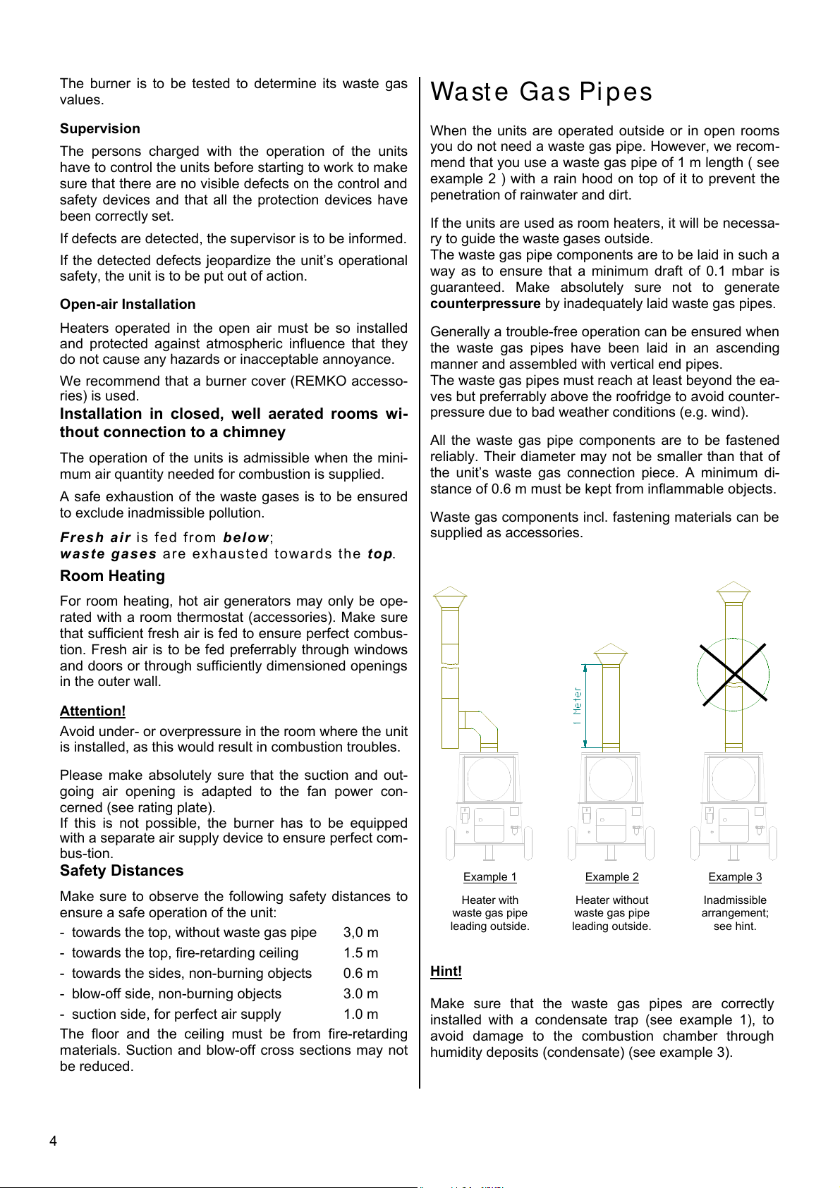
When the units are operated outside or in open rooms
you do not need a waste gas pipe. However, we recom-
mend that you use a waste gas pipe of 1 m length ( see
example 2 ) with a rain hood on top of it to prevent the
penetration of rainwater and dirt.
If the units are used as room heaters, it will be necessa-
ry to guide the waste gases outside.
The waste gas pipe components are to be laid in such a
way as to ensure that a minimum draft of 0.1 mbar is
guaranteed. Make absolutely sure not to generate
counterpressure by inadequately laid waste gas pipes.
Generally a trouble-free operation can be ensured when
the waste gas pipes have been laid in an ascending
manner and assembled with vertical end pipes.
The waste gas pipes must reach at least beyond the ea-
ves but preferrably above the roofridge to avoid counter-
pressure due to bad weather conditions (e.g. wind).
All the waste gas pipe components are to be fastened
reliably. Their diameter may not be smaller than that of
the unit’s waste gas connection piece. A minimum di-
stance of 0.6 m must be kept from inflammable objects.
Waste gas components incl. fastening materials can be
supplied as accessories.
Example 1
Heater with
waste gas pipe
leading outside.
Hint!
Make sure that the waste gas pipes are correctly
installed with a condensate trap (see example 1), to
avoid damage to the combustion chamber through
humidity deposits (condensate) (see example 3).
Example 2
Heater without
waste gas pipe
leading outside.
Example 3
Inadmissible
arrangement;
see hint.
4

Saf et y Fa cil i t y
Triple combination control according to DIN 3440
The device has 3 functions:
1. Fan Control (TR)
The tripping point is set with the adjusting lever (fan).
Rated value approx. 35 to 40°C.
2. Burner Temperature Monitor (TW)
The tripping point is set with the adjusting lever
(burner). Rated value approx. 110 to 115°C.
3. Safety Temperature Limiter (STB)
The tripping point is fixed according to DIN 3440.
After tripping, a burner restart is prevented.
The reset button is operated from outside.
Before a reset, check the operating conditions
G
of the device to ensure that the STB-
temperature is not exceeded again.
TR
Switching
lever
Switching Lever
"AUTO" Automatic control of the air supply fan via fan
control (TR) depending on the temperature of the air.
"MAN" The fan works independent of the temperature
of the air and can be used for continuous ventilation.
Note!
The device is equipped with a sensor monitoring feature
and is cold-resistant down to -20°C; below -20°C the de-
vice switches off; when the temperature rises above this
temperature, it switches on again.
When the sensor or the capillary tube is damaged, or
when an overtemperature of approximately 220°C is re-
ached, the filling medium is emptied and the device per-
forms a safety switch-off operation.
The device is no longer operable and must be replaced.
When the safety facility has to be replaced, take care not
to damage or excessively bend the capillary tubes. Use
only the original spare part, reference no. 1102561.
STB
TW
St ar t in g
Make sure to charge a person with the operation and
supervision of the unit who has been instructed
sufficiently regarding the handlings concerned.
Prior to starting, the unit is to be checked to make sure
that there are no visible defects on the control and
safety devices, that the unit has been installed correctly
and that it has been properly connected to the mains.
• Install unit in a stable position.
• Make sure that air is supplied for combustion.
• Make sure that the air can be sucked in and be
exhausted freely.
• Avoid overpressure and underpressure in the room
where the unit has been installed.
• Make sure that enough fuel is supplied.
(only use clean fuel oil EL and diesel, respectively)
Attention!
A sufficient quantity of free-flowing fuel oil must be
available even with low outside temperatures.
Paraffine formation can start even at a temperature of
5° C. Adequate measures are to be taken to avoid this.
Hint!
Any additional clauses of the relevant building
regulations and technical rules for combustible liquids
(TRBF 210 and 280”) are to be observed.
The waste gas values of the oil- or gas-burner are to be
checked and adjusted properly by authorized experts in
accordance with the local conditions.
Connection to the Mains
The units are operated with alternating current of 230 V.
Connection to the mains is carried out by means of an
installed mains cable with earthing-contact plug.
Possibly required extension cables must be selected
according to the existing cable length, the unit’s
connecting line and the intended purpose.
All extension cables are to be used only after
having been removed from the roller.
• Do not bend the sensor spirals near to solder points.
• When mounting, the sensor spirals may not be dama-
ged or bended sharply edged.
• The sensors must be fixed in the mounting brackets
provided by the factory.
• The sensors must always be free from dust and dirt.
Do not jumper or obstruct the safety features while the heater is in operation!
G G
Put operating switch (1) into “0” position
( = OFF).
5
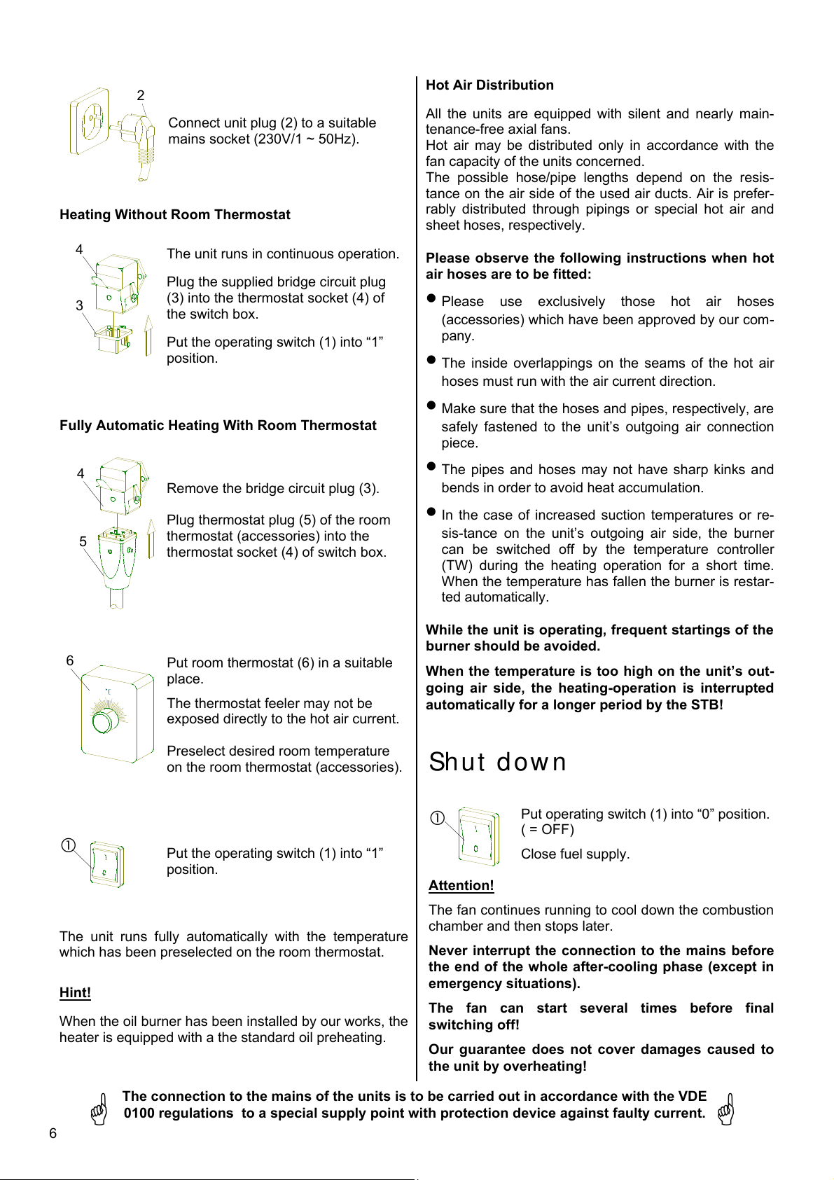
2
Connect unit plug (2) to a suitable
mains socket (230V/1 ~ 50Hz).
Heating Without Room Thermostat
4
3
Fully Automatic Heating With Room Thermostat
The unit runs in continuous operation.
Plug the supplied bridge circuit plug
(3) into the thermostat socket (4) of
the switch box.
Put the operating switch (1) into “1”
position.
Hot Air Distribution
All the units are equipped with silent and nearly main-
tenance-free axial fans.
Hot air may be distributed only in accordance with the
fan capacity of the units concerned.
The possible hose/pipe lengths depend on the resis-
tance on the air side of the used air ducts. Air is prefer-
rably distributed through pipings or special hot air and
sheet hoses, respectively.
Please observe the following instructions when hot
air hoses are to be fitted:
• Please use exclusively those hot air hoses
(accessories) which have been approved by our com-
pany.
• The inside overlappings on the seams of the hot air
hoses must run with the air current direction.
• Make sure that the hoses and pipes, respectively, are
safely fastened to the unit’s outgoing air connection
piece.
4
Remove the bridge circuit plug (3).
Plug thermostat plug (5) of the room
5
6
The unit runs fully automatically with the temperature
which has been preselected on the room thermostat.
Hint!
When the oil burner has been installed by our works, the
heater is equipped with a the standard oil preheating.
thermostat (accessories) into the
thermostat socket (4) of switch box.
Put room thermostat (6) in a suitable
place.
The thermostat feeler may not be
exposed directly to the hot air current.
Preselect desired room temperature
on the room thermostat (accessories).
Put the operating switch (1) into “1”
position.
• The pipes and hoses may not have sharp kinks and
bends in order to avoid heat accumulation.
• In the case of increased suction temperatures or re-
sis-tance on the unit’s outgoing air side, the burner
can be switched off by the temperature controller
(TW) during the heating operation for a short time.
When the temperature has fallen the burner is restar-
ted automatically.
While the unit is operating, frequent startings of the
burner should be avoided.
When the temperature is too high on the unit’s out-
going air side, the heating-operation is interrupted
automatically for a longer period by the STB!
Shut d ow n
Attention!
The fan continues running to cool down the combustion
chamber and then stops later.
Never interrupt the connection to the mains before
the end of the whole after-cooling phase (except in
emergency situations).
The fan can start several times before final
switching off!
Our guarantee does not cover damages caused to
the unit by overheating!
Put operating switch (1) into “0” position.
( = OFF)
Close fuel supply.
6
The connection to the mains of the units is to be carried out in accordance with the VDE
0100 regulations to a special supply point with protection device against faulty current.
G
G

M ai nt en an ce
The unit is to be maintained regularly whereby some
fundamental rules are to be observed to ensure a long
service life and trouble-free operation.
Use a clean slightly humid cloth for cleaning and wiping
the dirt off the surface. In case of obstinate dirt only sui-
table cleaning agents should be used.
Prior to starting any work make sure to pull
the mains plug out of the mains socket!
G
• The unit is to be kept free from dust and other depo-
sits and is to be cleaned only with a dry or humid
cloth (do not use water jet).
• Do not use any aggressive cleaning agents or those
which are harmful or environmentally unfriendly.
• Do not use cleaning agents which contain solvents.
• Use only clean fuel oil EL and diesel, respectively
(make sure to avoid paraffine formation).
• Check oil filters or gas filters regularly and replace
dirty filters.
• Check whether the unit is free from mechanical da-
mage, if not, replace faulty parts.
• Check fan wings and combustion chamber with heat
exchanger in regular intervals and clean them when
they are dirty.
• Check oil tank regularly and clean it when necessary
to remove dirt and foreign matters.
• Make sure that the waste gas and combustion air
can be always evacuated properly.
• Check safety devices regularly.
• The unit is to be maintained and cleaned in regular
intervals.
• Keep feelers of triple combination control always free
from dust and dirt.
• Have the waste gas values of the oil or gas burner
checked regularly by authorized experts.
For safety reasons we recommend that you conclude
a maintenance contract!
• Make sure to store the unit in a dust-free and dry
place when it is not used for a longer period.
Ser vi ce
The complete unit including heat exchanger,
combustion chamber and oil burner is to be cleaned
from dust and dirt after every heating period, or even
earlier, depending on the operational conditions.
Expendable parts, such as flue gas suppressors,
gaskets, oil filter inserts, and oil nozzles are to be
checked and replaced, if necessary.
Heat Exchanger Cleaning
² Cut unit from the mains
² Disassemble connection piece for outgoing air (only
CLA 25/40/50)
² In addition CLA 100:
- disassemble jack ring (pos. 14)
- disassemble cover plate (pos. 1)
- disassemble upper insulation (pos. 12)
² Remove revision cover (pos. 22)
² Pull flue gas suppressor (pos. 22) out of unit
² Clean flue gas passes. Special cleaning brushes
can be obtained as accessories.
² Clean flue gas suppressor or replace them,
if necessary.
² Check gaskets and revision cover and replace,
if necessary.
² Assembly is to be carried out in reverse order,
where-by you should make sure that the gaskets
and the revision cover is correctly seated.
Combustion Chamber Cleaning
² Cut unit from the mains
² Remove burner
² Clean combustion chamber through its opening by
means of a vacuum cleaner. Special cleaning sets
can be obtained as accessories to the REMKO in-
dustrial vacuum cleaner.
² Install burner; check flange gasket and replace,
if necesary.
Make sure that the burner is exclusively maintained
by authorized experts.
Make sure to observe the limit values for waste gas
losses according to the regulations for small-sized
fireplaces.
Setting and maintenance is to be carried out only by authorized experts!
G G
7

CLA 2 5 / 4 0 / 5 0
CLA 1 0 0
8
We reserve the right to make modifications in dimensions and construction in the interests of technical progress.
Nr.
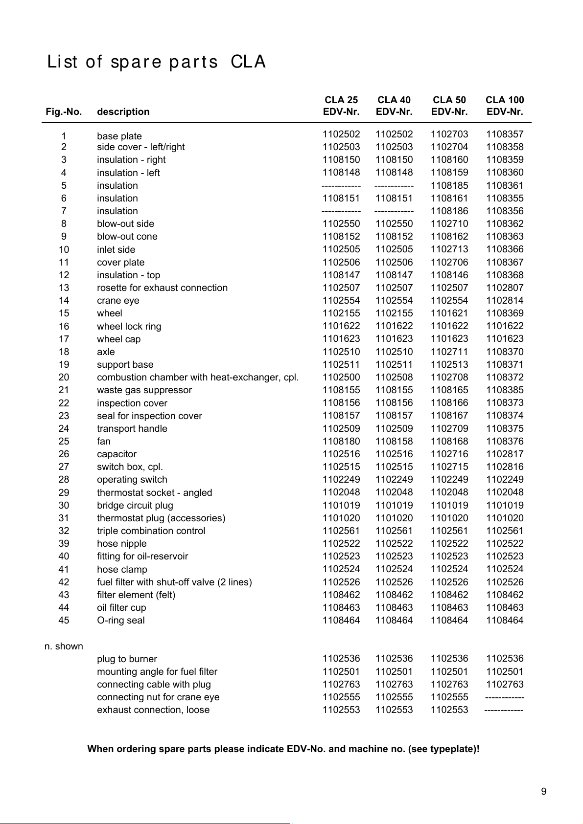
Li st o f spa r e pa r ts CLA
Fig.-No. description
1 base plate
2 side cover - left/right
3 insulation - right
4 insulation - left
5 insulation
6 insulation
7 insulation
8 blow-out side
9 blow-out cone
10 inlet side
11 cover plate
12 insulation - top
13 rosette for exhaust connection
14 crane eye
15 wheel
16 wheel lock ring
17 wheel cap
18 axle
19 support base
20 combustion chamber with heat-exchanger, cpl.
21 waste gas suppressor
22 inspection cover
23 seal for inspection cover
24 transport handle
25 fan
26 capacitor
27 switch box, cpl.
28 operating switch
29 thermostat socket - angled
30 bridge circuit plug
31 thermostat plug (accessories)
32 triple combination control
39 hose nipple
40 fitting for oil-reservoir
41 hose clamp
42 fuel filter with shut-off valve (2 lines)
43 filter element (felt)
44 oil filter cup
45 O-ring seal
n. shown
plug to burner
mounting angle for fuel filter
connecting cable with plug
connecting nut for crane eye
exhaust connection, loose
CLA 25 CLA 40 CLA 50 CLA 100
EDV-Nr. EDV-Nr. EDV-Nr. EDV-
1102502 1102502 1102703 1108357
1102503 1102503 1102704 1108358
1108150 1108150 1108160 1108359
1108148 1108148 1108159 1108360
------------ ------------ 1108185 1108361
1108151 1108151 1108161 1108355
------------ ------------ 1108186 1108356
1102550 1102550 1102710 1108362
1108152 1108152 1108162 1108363
1102505 1102505 1102713 1108366
1102506 1102506 1102706 1108367
1108147 1108147 1108146 1108368
1102507 1102507 1102507 1102807
1102554 1102554 1102554 1102814
1102155 1102155 1101621 1108369
1101622 1101622 1101622 1101622
1101623 1101623 1101623 1101623
1102510 1102510 1102711 1108370
1102511 1102511 1102513 1108371
1102500 1102508 1102708 1108372
1108155 1108155 1108165 1108385
1108156 1108156 1108166 1108373
1108157 1108157 1108167 1108374
1102509 1102509 1102709 1108375
1108180 1108158 1108168 1108376
1102516 1102516 1102716 1102817
1102515 1102515 1102715 1102816
1102249 1102249 1102249 1102249
1102048 1102048 1102048 1102048
1101019 1101019 1101019 1101019
1101020 1101020 1101020 1101020
1102561 1102561 1102561 1102561
1102522 1102522 1102522 1102522
1102523 1102523 1102523 1102523
1102524 1102524 1102524 1102524
1102526 1102526 1102526 1102526
1108462 1108462 1108462 1108462
1108463 1108463 1108463 1108463
1108464 1108464 1108464 1108464
1102536 1102536 1102536 1102536
1102501 1102501 1102501 1102501
1102763 1102763 1102763 1102763
1102555 1102555 1102555 ------------
1102553 1102553 1102553 ------------
When ordering spare parts please indicate EDV-No. and machine no. (see typeplate)!
9

Techni cal Da t a
Series CLA 25 CLA 40 CLA 50 CLA 100
rated heat power max. kW 29 36 58 106
ratedheat output kW 26,5 30 50 91
rated air output m³/h 1150 1600 3200 5200
fuel heating oil EL or liquid gas
fuel consumption, max. kg/h 2,6 3,0 5,0 9,0
nozzle (Steinen) 2) USG/°S 0,65/60° 0,75/60° 1,25/60° 2,25/60°
pump-pressure (mit ÖV)
flue gas loss % 9,4 10 10 10
electrical connection 1~ V 230 230 230 230
frequency Hz 50 50 50 50
rated current A 1,95 1,95 3,3 4,7
power take-up kW 0,4 0,4 0,7 1,0
capacitor (fan) µF 3 3 8 14
fuse protection (required) A 10 10 10 10
sound pressure level L
air outlet Ø mm 285 285 345 500
waste gas connection Ø mm 180 180 180 200
weight (without burner) kg 110 110 153 260
dimensions: length, total mm 1385 1385 1685 1955
width, total mm 640 640 770 1020
hight, total mm 930 930 1030 1240
1) noise measuring (without burner) DIN 45635 - 01 - KL 3
2) The mentionend nozzle-sizes and pump-pressures result from coordination tests on the test bench. The fuel consumption had been
measured out.
On account of tolerances and oil-temperature these specifications must be considered as guiding values.
2)
bar 11-12 11-12 11-12 11-12
1)
pA 1m
dB(A) 54 56 66 64
Dimensions and specifications subject to change
Wi r i ng Di a gr am
S = operating switch
KL = terminal strip
SK = switch box, cpl.
C = capacitor
(CLA 100: capacitor in
terminal box of fan)
RT = room thermostat socket
M = fan motor
TR = fan control thermostat
STB = safety temperature limiter
TW = burner temperature monitor
KB = triple combination control, cpl.
WS = plug to burner, 7 poles
(only if burner has been
installed by our works)
blau = blue
braun = brown
schwarz = black
10

Troub l esh oot ing I n st r u ct i on s
Unit does not start:
² Check connection to the mains
² Check safety thermostat (STB)
² Put operating switch into “I” position
² Check whether bridge circuit plug has been plugged
in correctly
² Check room thermostat and its plug, respectively.
The temperature set at the room thermostat must be
higher than the room temperature.
² Set change lever of triple combined regulator to
“MAN” position. When the fan starts running the fault
is to be eliminated in the burner area.
Burner does not start:
² Check whether fuel filter is dirty
² Open stop valve of fuel filter
² Check whether the fuel quantity in the reservoir is
still sufficient
² Check whether paraffine has been formed in the
filter and fuel (this can happen even at 5 °C)
² Check whether oil hoses have been damaged (air
suction, air bubbles)
² Check safety temperature limiter (STB); if the STB
has been released make sure to find the reasons
why, e.g.:
l unit could not cool down, as the electric power
has been cut off
l temperature of blown out air too high because
of inadequate air guidance
l no free air inlet and outlet
² Check temperature controller (TW) in the triple
combined regulator (by bridging)
² Check whether the feeler or capillary tube of the
triple combined regulator has been damaged (see
description “safety device”).
² Check whether the interference lamp of burner relay
has been lit up;
² if so, unlock relay by pressing the anti-interference
button.
The burner tries to start (take delayed burner start
due to oil preheating into account).
Attention!
If the burner is switched off once more after the star-
ting phase because of a fault, another unlocking
may not be carried out before a waiting time of 5 mi-
nutes has lapsed.
Make sure to avoid any further unlocking (danger of
deflagration).
For safety reasons all repairs and maintenance
work regarding the burner is to be carried out
only by authorized experts.
Fan Does not Start:
² Check whether fan wing is freely running
² Check whether electric cable of fan has been
damaged
² Check operating capacitor of fan
² Check fan regulator (TR) in the triple combined re-
gulator (by bridging).
Attention!
Repairs regarding the electric installations may
be carried out only by authorized electricians!
During the unit’s operation safety devices may
neither be bridged nor blocked!
If all the controls regarding the different functions have been carried
out without a result, you should contact an authorized service center.
Important Hint!
An operation/use other than that indicated in these instructions is prohibited! In the case of
non-observation we will not be held responsible and our guarantee will become void.
Any claims under guarantee regarding materials can be accepted only when the orderer or his customer has
filled in completely the “guarantee certificate” which is enclosed with every REMKO-heater and has
returned it to REMKO GmbH & Co. KG in due time after the unit’s sale and commissioning.
11

REMKO GmbH & Co. KG
Klima- und Wärmetechnik
D-32791 Lage · Im Seelenkamp
12
D-32777 Lage · Postfach 1827
Telefon (0 52 32) 606 - 0
Telefax (0 52 32) 606260
 Loading...