

REMKO BL
BL 261, BL 351
Wall - room air conditioner in split design
with quick-release coupling system
Operation · Technology · Spare parts
Edition GB - D04


Contents
Safety notes
4
Environmental protection and recycling
Warranty
Intended use
Transportation and packaging
System description
Operation
Decommissioning
Care and maintenance
Troubleshooting and customer service
Installation instructions for qualified personnel
Installation
Connection of quick-release couplings
Leak testing
4
4
4
5
5
6-12
12
12-13
14-15
16-19
19
20
21
Pumping down to vacuum
Condensate draining and ensured discharge
Electrical connection
Electrical connection diagram
Electrical drawings
Before commissioning
Adding refrigerant
Commissioning
Unit dimensions
Exploded views
Spare parts lists
Technical data
EC – Declaration of Conformity
21
21
21-22
22
23
24
24
24-25
26
27-28
27-28
29
30
Made by REMKO
Carefully read this operating manual prior to commissioning / using
the equipment!
These instructions are an integral part of the unit and must always be
kept in the vicinity of the installation location or on the unit itself.
This operating manual is a translation of the German original.
Subject to modifications; no liability accepted for errors or misprints!
3

REMKO BL
Safety notes
Carefully read this operating
manual before starting the unit
for the first time. It contains
useful tips and notes as well as
hazard warnings to prevent injury
or material damage ! . Failure
to follow the directions in this
manual not only presents a danger
to people, the environment and
the system itself, but will void any
claims for liability.
■ Keep this operating manual and
the refrigerant data sheet near
to the unit.
■ The units and components
should be set up and installed
only by qualified personnel.
■ The set-up, connection,
and operation of the unit and its
components must take place in
accordance with the operating
conditions stipulated in this
manual and comply with all
applicable local regulations.
■ Mobile units must be set up
securely on suitable surfaces and
in an upright position. Stationary
units must be permanently
installed for operation.
■ Modification of units and
components supplied by
REMKO is not permitted and
can cause malfunctions.
■ Units and components may
not be operated in areas where
there is an increased risk of
damage. Observe the minimum
clearances.
■ The electrical supply is to be
adapted to the requirements
of the units.
■ The operational safety of
the units and components
is only assured if they are
fully assembled and used as
intended. Safety devices may
not be modified or bypassed.
■ Do not operate units or
components with obvious
defects or signs of damage.
■ All housing parts and openings
in the unit, e.g. air intakes and
outlets, must be free of foreign
objects, fluids, or gases.
■ The units and components must
be kept at an adequate distance
from flammable, explosive,
combustible, abrasive and dirty
areas or atmospheres.
■ Contact with some parts of the
unit or components can result in
burns or other injuries.
■ Installation, repair and
maintenance work may be
carried out by authorised
specialists only. Visual
inspections and cleaning can
be performed by the operator as
long as power is disconnected
from the equipment.
■ To preclude any danger from the
unit, take appropriate hazardprevention measures when
performing installation, repair or
maintenance work or cleaning
the unit.
■ The units and components
should not be exposed to any
mechanical load, extreme levels
of humidity or direct exposure
to sunlight.
Environmental
protection
and recycling
Disposing of packaging
All products are carefully packaged
using environmentally friendly
materials prior to transportation.
You can make a valuable
contribution to reducing waste
and sustaining raw materials by
only disposing of packaging at
approved collection points.
Disposing of the units and
their components
Only recyclable materials are used
in the manufacture of the units
and components.
Help protect the environment
by ensuring that the units or
components (for example
batteries) are not disposed of
in household waste, but only in
accordance with local regulations
and in an environmentally safe
manner, e.g. using authorised
disposal and recycling
specialists or council
collection points.
Warranty
In order to make warranty claims, it
is essential that the ordering party
or their representative complete
and return the "certificate of
warranty" to REMKO GmbH
& Co. KG at the time when the
equipment is purchased and
commissioned.
The warranty conditions are
detailed in the "General business
and delivery conditions".
Furthermore, only the parties to
a contract can conclude special
agreements beyond these
conditions. In this case, first contact
your contractual partner.
Intended use
Depending on the model, the
units and the additional fittings
with which they are equipped are
only intended for private use as
an air-conditioner for the purpose
of cooling or heating the air in an
enclosed space.
Any different or additional use shall
be classed as non-intended use.
The manufacturer/supplier assumes
no liability for damages arising from
such use. The user bears the sole
risk in such cases.
Intended use also includes
working in accordance with the
operating manual and installation
instructions and complying with the
maintenance requirements.
4

Transportation and
packaging
The units are delivered in strong
transport packaging. Immediately
check the units on delivery and
make a note of any damage or
missing parts on the delivery note.
Inform the forwarding agent and
contractual partner.
No warranty can be assumed for
later claims.
Cooling circuit diagram for the outdoor component
Condenser fan
M
Reverse flow valve
M
Capillary tube throttle elementFilter dryerCondenser
Compressor
Connection for
pressure gauge
Quick-release
coupling
connection valve
Suction line
Quick-release
coupling
connection valve
Injection pipe
System description
The BL 261 and BL 351 room air
conditioning units have a REMKO
BL...AT outdoor component as
well as a BL...IT indoor unit.
The outdoor component serves to
output the heat extracted by the
indoor unit from the room being
cooled.
In heater operation, the heat taken
up by the outdoor unit can be
discharged by the indoor unit into
the room to be heated.
The outdoor component can be
installed outdoors or indoors.
The latter requires the fulfilment of
certain conditions. The indoor unit
is designed to be mounted high up
on indoor walls. It is operated by
an infrared remote control.
The outdoor component consists of
a cooling circuit with compressor,
fin condenser, condenser fan,
reverse flow valve, quick-release
couplings and throttle element.
The outdoor component is
controlled by the controller in the
indoor unit.
The indoor unit consists of a fin
vaporiser, vaporiser fan, controller
and condensation tray.
Floor consoles, wall consoles and
condensation pumps are available
as accessories.
Cooling circuit diagram for indoor unit
Vaporiser
System configuration
Indoor area
Indoor unit
Condensate line
Outdoor area
Outdoor component
Condensate line
Vaporiser fan
Suction line connection
with quick-release coupling
Injection pipe connection
with quick-release coupling
Mains cable
Control cable
Injection pipe
Suction line
Shut-off valve with
quick-release coupling
Condenser fan
The connection between the indoor unit and outdoor component is effected
using the factory-supplied refrigerant pipes by means of quick-release couplings.
5

REMKO BL
Operation
The indoor unit is easy to operate using an infrared remote control. This is supplied as standard. The indoor unit
beeps to acknowledge the correct transmission of data. If it is not possible to program the indoor unit using the
remote control, it can also be operated manually.
Manual mode
The indoor units can be
commissioned
manually. After the air inlet screen
has been opened, the inner
recessed key can be pressed and
automatic mode can be activated.
In manual operation, the following
settings apply:
Cooling mode: last setting
Fan speed: AUTO
Heating mode: last setting
Fan: AUTO
Press a key on the infra-red
remote control to interrupt manual
operation.
Display on indoor unit
The display illuminates according to the settings.
Display on indoor unit
Swing mode
Cooling mode
Automatic mode
Sleep function
Temperature unit
Display
of coded error
messages, room and
target temperature
Heating mode
Timer
Dehumidification mode
Fan speed
Infrared remote control
The infrared remote control
sends the programmed settings
a distance of up to 6 m to the
receiver of the indoor unit.
Data will only be received correctly
if the remote control is pointed
at the receiver and no objects are
obstructing the transmission path.
First insert the supplied batteries
(2 each, type AAA) into the remote
control. To do so, remove the flap
from the battery compartment and
insert the batteries the correct way
around (see markings).
max. distance 6 m
max. 6 m
! ATTENTION
Problems are shown in code
(see Troubleshooting and
Customer service section).
TIP
Help save on energy consumption in stand-by mode! If the
device, system or component
is not in use, we recommend
disconnecting the power supply. Components with a safety
function is excluded from our
recommendation!
NOTE
Immediately replace flat
batteries with a new set,
otherwise there is a risk of
leakage.
It is recommended that the
batteries are removed if the
equipment is shut down for
long periods.
6

Keys on the remote control
Keys on the remote control
"ON/OFF" key
Press this key to operate the
unit.
"TOO HOT" key
Press this key to decrease
the desired temperature to
16°C.
"TOO COLD" key
Press this key to increase the
desired temperature to 31°C.
"MODE" key
Press this key to select the
operating mode.
The indoor unit has 4 modes:
2. Cooling mode
In this mode, the warm air in
the room is cooled down to the
desired temperature.
3. Dehumidification mode
In this mode the room is mainly
dehumidified and the adjusted
temperature is maintained.
4. Heating mode
In this mode, the warm air in
the room is warmed to the
desired temperature.
"FAN" key
Press this key to set the
desired fan speed. 4 speeds
are available: Automatic, high,
medium and low fan speed.
"FINS" key
Press this key to set the desired
fin position. 5 positions and
an oscillating are function
available.
"SLEEP" key
Press this key to automatically
increase or decrease the target
temperature by 1°C every hour
in cooling and heating mode
respectively.
"SWING" key
Press this key to directly
activate the oscillating function
of the fins for better air
distribution in the room.
"TIMER ON" key
Press this key to program
the automatic activation time
of the unit within the next
24 hours.
"TIMER OFF" key
Press this key to program the
automatic switch-off time
of the unit within the next
24 hours.
"HR" key
Press this key to set the hours.
"MIN" key
Press this key to set the
minutes.
"RESET" key
(in battery compartment)
Press this key to reset the
remote control to its factory
settings.
"CLOCK" key
(in battery compartment)
Press this key to activate the
time setting.
"DISPLAY" key
Press this key to switch the
display on and off (no influence
on device functionality)
1. Automatic mode
In this mode, the unit works in
cooling or in heating mode.
7

REMKO BL
Key functions
A symbol is shown on the display to indicate that the settings are being transferred.
Stand by of remote control
RESET key
The remote control standby mode is signalled by the blinking dot on the
remote control.
The remote control can be reset by pressing the RESET key in the battery
compartment. The time can then be programmed (see "CLOCK key").
RESET 5 sec. Setting the clock
CLOCK Key
ON/OFF key
The time can be programmed by pressing the CLOCK key inside the
battery compartment. "CLOCK" blinks in the display and the current
time is set via the HR. and MIN. key. Programming is completed by
pressing the CLOCK key again. The display will stop blinking.
CLOCKHR/MINCLOCK
Your air conditioner is activated and deactivated by pressing the ON /
OFF key. The programmed settings and adjustment values from before
the unit was turned off will appear on the display.
ON/OFF ON/OFF
8

▲/▼ Keys
The ▼ key can be used to reduce the desired target temperature, the
▲ key can be used to increase it. In automatic mode, the temperature
can be increased or decreased by 1°C. In dehumidification mode, no
temperature adjustment can be made.
MODE key
Cooling mode
▼
▼
Automatic mode
▲
▲
The display turns off
after 1 min.
Use the MODE key to switch between individual operating modes. A total of 4 modes are available:
1. Automatic cooling or heating operation
2. Cooling primarily summer mode
3. Dehumidifying operating mode for summer or winter
4. Heating mainly a winter operating mode
Automatic Cooling Dehumidification Heating
MODEMODEMODE
AUTOMATIC MODE
COOLING mODE
In automatic mode, the controller autonomously selects between heating
and cooling operation when the unit is first switched on. The control
range lies between 22°C and 26°C. This can be increased or decreased
with the ▲/▼ keys.
MODE
AUTOMATIC
In cooling mode, the air in the room is cooled to the set target
temperature. The desired room temperature is set with the ▲/▼ keys
in 1°C increments. If the room temperature is 0.5°C above the selected
target temperature, then the interior unit starts to cool the air in the
room. If the temperature falls to approx. 1°C below the set room
temperature, the controller will switch off cooling mode. To protect the
compressor, the controller only turns cooling on again after a wait time of
3 minutes.
MODE
COOLING
MODE
9

REMKO BL
DEHUMIDIFICATION MODE
HEATING mode
In dehumidification mode, the target temperature is set to 24°C. Due to
the low temperature of the refrigerant, the temperature of the air at the
condenser falls below the dew point. The excess moisture in the air is
condensed by the vaporiser, the room is dehumidified. The fan speed
is permanently set to the lowest setting in order to achieve a maximum
level of dehumidification. The compressor switches on and off in intervals
between 17°C and 24°C.
MODE
DEHUMIDIFICATION
MODE
In heating mode, you can heat the room in spring or autumn. The
selected room temperature is set with the ▲/▼ keys in 1°C increments.
If the room temperature is 1°C below the selected target temperature,
the indoor unit will start to heat the air in the room. If the set room
temperature is exceeded by approx. 1°C, the controller will switch off
heating mode. To protect the compressor, the controller will wait 3
minutes before switching on the heating mode again.
MODE
HEATING MODE
FAN Key
FINS Key
SWING key
The fan speed can be adjusted with this key. A selection can be made
between low, medium, high and automatic fan speed.
FANFANFAN FAN
The air discharge fins are individually adjusted with this key.
A selection can be made between 5 positions and an oscillating function.
The oscillating function of the air fins can be adjusted with this key.
This makes it possible to switch directly between a preset position and
the oscillating function. The air distribution in the room is improved with
the swing function.
10
SWINGSWINGSWING

SLEEP Key
A programming function is activated with this key, which increases the
target temperature in cooling mode by 1°C after one hour and by 2°C
after 2 hours. In heating mode, the target temperature is decreased
by 1°C after one hour by 2°C after 2 hours. The unit switches off
automatically after 8 hours.
SLEEPSLEEPSLEEP
TIMER Key
TIMER Key ON
TIMER Key OFF
The activation and switch-off time can be programmed with this key.
The timer is activated and the clock display is switched off by pressing
the Timer On or Timer Off keys. The timer symbol for the switch-on/
off time will flash. The timer display on the indoor unit illuminates.
The desired switch on or switch off time is set by pressing the keys HR.
and MIN. Following adjustment, the timer symbol blinks for another
30 seconds. When the programmed time has been reached, the unit
automatically switches on or off. If the indoor unit is automatically
switched on, the mode, temperature and fan speed for the last setting
are activated. The switch on/off time can be prematurely cancelled by
pressing the appropriate timer key or the ON/OFF key. The timer display
on the indoor unit turns off.
Timer on HR/MIN 30 sec.
TIMER Key ON/OFF
Timer off HR/MIN 30 sec.
The controller turns the unit on and off daily at the programmed time.
During operation, all settings and the timer symbol can be seen on the
display. When not in operation, the display 0->1 and the timer symbol
can be seen.
Example:
Unit On Unit Off
The controller turns on at 10:20.
The unit is in operation until 05:00.
11

REMKO BL
Manual air distribution
There are individually adjustable
fins for adjusting the horizontal air
distribution on the air discharge
side.
! ATTENTION
Moving interior parts such as
the fan may to cause injury
during operation!
Only make adjustments after
swing operation has been
turned off.
Decommissioning
Temporary
Decommissioning
1. Let the indoor unit run for 2
to 3 hours in circulation mode,
or in cooling mode at maximum
temperature, to extract any
residual humidity from the unit.
2. Shut down the system using the
remote control.
3. Switch off the voltage supply to
the unit.
4. Cover the unit as far as possible
with plastic foil in order to
protect it from the influences of
weather.
Manual air distribution
Shift lever left
Permanent
decommissioning
Ensure that equipment and
components are disposed of in
accordance with local regulations,
e.g. through authorised disposal
and recycling specialists or at
collection points.
REMKO GmbH & Co. KG or your
contractual partner will be pleased
to provide a list of certified firms in
your area.
Shift lever right
Care and maintenance
Regular care and maintenance
ensure the trouble-free operation
and long service life of the unit.
! ATTENTION
Prior to performing any work,
ensure that the equipment
is isolated from the voltage
supply and secured to prevent
accidental switch-on!
Care
■
Ensure that the indoor unit
and outdoor component are
protected against dirt, mould
and other deposits.
■
Clean the units with a damp
cloth. Do not use any caustic,
abrasive or solvent-based
cleaning products. Do not use
a jet of water.
12
■
Clean the fins on the indoor
unit and outdoor component
prior to long shutdown periods.

Maintenance
■
It is recommended that you
take out a maintenance
contract with an annual service
from an appropriate specialist
firm.
TIP
This ensures the operational
reliability of your system!
Cleaning the housing on
the indoor unit
1. Disconnect the supply voltage
to the equipment.
2. Open and fold the air inlet
guard on the front side
upwards.
3. Clean the guard and cover with
a soft, damp cloth.
4. Switch the supply voltage back
on.
Air filter for indoor unit
Clean the air filter at intervals of
no more than 2 weeks.
Reduce this interval if the air is
especially dirty.
Cleaning the filter on
the indoor unit
1. Disconnect the supply voltage
to the equipment.
2. Open the front side of the unit
by folding the guard upwards
and allowing it to engage
(figure 1).
3. Raise the filter and pull it out
pulling downwards.
Type of task
Checks/Maintenance/Inspection
General
Measure voltage and current
Check function of compressor/fans
Check function of fan
Dirt on condenser/vaporiser
Check refrigerant fill quantity
Check condensate drain
Inspect insulation
Check moving parts
Sealing test for cooling circuit
4. Clean the filter with
a commercially available
vacuum cleaner. Turn the dirty
side upwards (figure 2).
5. Dirt can also be removed
by carefully cleaning with
lukewarm water and mild
cleaning agents. Turn the dirty
side downwards (figure 3).
6. If water is used, let the filter dry
out properly in the air before
fitting it back into the unit.
7. Carefully insert the filter. Ensure
that it locates correctly.
8. Close the front side as
described above in reverse
order.
9. Switch the supply voltage back
on.
10.
Switch the unit on again.
Commissioning
Monthly
Half-yearly
Yearly
• •
• •
• •
• •
• •
• •
• •
• •
• •
• •
1 Fold the guard upwards
2 Cleaning using a vacuum cleaner
3
Cleaning with lukewarm water
Cleaning of condensation
pump (optional equipment)
An optional integrated or separate
condensation pump may be in the
indoor unit, which pumps out any
accumulated condensation into
higher positioned drains.
Observe the care and maintenance
instructions in the separate
Operating Instructions.
1)
13

REMKO BL
Troubleshooting and customer service
The units and components are manufactured using state-of-the-art production methods and tested several
times to verify their correct function. However, if malfunctions should occur, please check the functions as
detailed in the list below. Please inform your dealer if the unit is still not working correctly after all function
checks have been performed!
Malfunctions
Fault Possible cause Checks Remedial measures
The unit does not start or
switches itself off.
The unit does not respond
to the remote control.
Power outage, undervoltage,
defective mains fuse / main switch
in OFF position
Damaged mains cable
Wait time after switching on is
too short
Working temperature fallen below
/ exceeded
Electrical surges caused by
thunderstorms
Fault in external
condensation pump
Transmission distance too far /
receiver affected by interference
Defective remote control
Receiver or transmitter unit
exposed to excessive solar
radiation
Electromagnetic fields are
interfering with transmission
Key in remote control jammed /
two keys pressed at same time
Batteries in remote control are flat
Are all electrical
installations functioning correctly?
Are all electrical
installations functioning correctly?
Have approx. 5 minutes
elapsed since the restart?
Are the fans in the indoor unit
and outdoor component working
correctly?
Have there been lightning strikes
in the area recently?
Did the pump shut down due to
a fault?
Does the indoor unit beep when
pressing a key?
Is the unit running in manual
mode?
Does it function correctly in the
shade?
Does it function after removing
potential sources of interference?
Does the “Send” symbol appear
on the display?
Have new batteries been inserted?
Is the display incomplete?
Check the voltage and
if necessary, wait for it to come
back on
Repair by specialist
Schedule longer wait times
Take into account the temperature
range for the indoor unit and
outdoor component
Switch off the mains protection
and switch it back on /
have it checked by a specialist
Check and if necessary clean the
pump
Reduce the distance to less than
6 m or change position
Replace the remote control
Place the receiver and/or
transmitter unit in the shade
Signal is not transmitted when
sources of interference are
operational
Release the key / only press one
key
Insert new batteries
The unit is running but
only provides reduced or no
cooling or heating
performance.
Condensate is leaking out
14
Filter is unclean / air intake /
outlet blocked by foreign objects
Doors and windows open.
Heating/cooling output increases
Neither cooling nor heating mode
has been set
Fins on outdoor component
blocked by foreign objects
Leaking cooling circuit
Drainage pipe on collection
container clogged / damaged
Faulty external condensation
pump or float
Condensation has collected in the
condensate line
Condensate does not drain off
Have the filters been cleaned? Clean the filters
Have structural /
usage modifications been made?
Is the cooling/heating symbol
shown on the display?
Is the fan on the outdoor
component running? Are the fins
unobstructed?
Are there signs of frost on
the fins of the indoor unit?
Is unrestricted condensate
discharge ensured?
Is the condensation tray full and
the pump running?
Has the condensate line been
laid on an incline and is it
unobstructed?
Are the condensate lines unblocked
and is there a steady incline?
Are the condensation pump and
float switch functioning correctly?
Close windows and doors / install
additional units
Correct the settings for the unit
Check the fan or winter controller,
reduce the air resistance
Repair by specialist
Clean the drainage pipe and
collection container
Call out a specialist to replace the
pump
The condensate line must be on
an incline. If necessary, clean the
line
Install the condensate line on
an incline and clean if necessary
/ if the float switch or the
condensation pump is defective,
have them replaced

Fault indication by flashing code
Display Cause Required action
E1 Indoor unit probe air circulation defective Contact specialist dealer
E2 Indoor unit probe frost protection defective Contact specialist dealer
E4
E5
E6 Bridge inner control cable interrupted Check bridge plug
Cooling mode: No cooling output after 30 minutes
Heating mode: No heating output after 30 minutes
Cooling mode: Frost protection has responded
Heating mode: Overheating protection has tripped
Contact specialist dealer
Contact specialist dealer
15

REMKO BL
Installation instructions for qualified personnel
Important notes prior to
installation
■
Transport the unit in its original
packaging as close as possible
to the installation location.
This helps to prevent damage
during transportation.
■
Check the contents of the
packaging for completeness
and check the unit for visible
transport damage. Report any
damage immediately to your
contractual partner and the
shipping company.
■
Lift the unit on the corners and
not on the refrigerant
or condensate connections.
■
The refrigerant pipes
(injection and suction line),
valves and connections must be
insulated impervious to vapour
diffusion. If necessary, also
insulate the condensate line.
■
Select an installation location
which allows air to flow
freely through the intake and
outlet (see section "Minimum
clearances").
■
Do not install the unit in the
immediate vicinity of devices
which generate intensive
thermal radiation. Installation
near sources of thermal
radiation reduces the output of
the unit.
■
Only open the shut-off valves
of the refrigerant pipes after
installation is complete.
■
Seal off open refrigerant lines
with suitable caps or adhesive
strips to prevent the infiltration
of moisture and never kink or
compress the refrigerant pipes.
■
Avoid unnecessary bends.
You thereby minimise loss of
pressure in the refrigerant pipes
and ensure clear return flow of
the compressor oil.
■
Take special precautions with
regard to the oil return if
the outdoor component is
located above the indoor unit.
See section "Oil return flow
measures".
■
Only use the refrigerant pipes
provided in the delivery and
only removethe protective caps
shortly before connection to the
outdoor component.
■
Make all electrical connections
in accordance with applicable
DIN and VDE standards.
■
Always attach electrical lines
properly in electrical clamps,
otherwise a fire could result.
! ATTENTION
Both units and the extension
lines are pre-filled with
refrigerant.
Suitable protective
must be worn during
installation
.
clothing
16

Wall openings
■
A wall opening of at least
70 mm diameter and 10 mm
incline from the inside to the
outside must be made for each
indoor unit.
■
We recommend that the inside
of the opening is padded or
lined, e.g. using a PVC pipe,
to prevent the lines being
damaged.
Selection of installation location
Indoor unit
The indoor unit is designed for
horizontal wall installation above
doors. However, it can also be
used in the upper wall area
(min. 1.75 m above the floor).
The indoor unit is not suitable for
installation on roof inclines.
Outdoor component
Wind
If the unit is being installed in
windy areas, ensure that the
warm outlet air discharges in the
prevailing wind direction. If this
is not the possible, it may be
necessary to install a windbreak
(to be provided by the customer).
Ensure that the windbreak does
not adversely affect the air intake
to the unit.
■
After installation, the wall
opening should be closed off
with a suitable sealant. Do not
use materials containing cement
or lime!
Lines in the wall opening
Control cable
PVC pipe
Suction line
Condensate line
Injection pipe
Installation materials
The indoor unit is attached to
the wall by a wall bracket and
4 screws (to be provided by the
customer).
The outdoor component is
attached by 4 screws and a wall
bracket to the wall or fixed by
a floor bracket to the ground.
The outdoor component is
designed for horizontal installation
on a base in outdoor areas.
The installation site must be level,
flat and firm. The unit should also
be secured to prevent toppling.
The outdoor component can be
set up outside as well as inside
a building. For external installation,
please observe the following
notes to protect the unit from the
influence of the weather.
Rain
For attic or roof set up, the unit
should be installed with at least
10 cm ground clearance. A floor
bracket is available as an optional
accessory.
Sun
The condenser on the outdoor
component emits heat.
Exposure to direct sunlight will
further increase the temperature
of the fins and reduce the
heat output of the finned
heat exchanger. The outdoor
component should be installed on
to the north side of the building
whenever possible. If necessary,
take measures to provide sufficient
shade (responsibility of customer).
One possible solution is to build
a small roof. These measures
should not affect the flow of warm
outlet air.
Windbreak
Wind
Snow
The unit should be wall-mounted
in areas of heavy snowfall.
Installation should then be at least
20 cm above the expected level
of snow to prevent snow from
entering the outdoor component.
An optional wall bracket is
available as an accessory.
Minimum clearance to snow
Snow
20 cm
17
REMKO BL
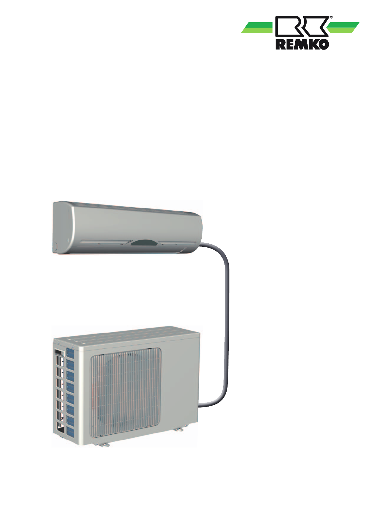
Installation inside buildings
■
Ensure that heat can dissipate
adequately when placing the
outdoor component in cellars,
lofts, adjoining rooms or halls
(figure 4).
■
Install an additional fan with
a rated flow comparative to
that of the outdoor component
being installed in the room
and which can compensate
any additional pressure loss in
ventilation ducts (figure 4).
■
Ensure a continuous and
unobstructed air flow from
outside, preferably using
sufficiently large air intakes
placed opposite each other
(figure 4).
4 Installation inside buildings
Warm air
additional
fan
Light
well
Warm air
■
Comply with any regulations
and conditions affecting
the statics of the building.
If necessary, fit acoustic
installation.
Outdoor component
Fresh
cold air
Light
well
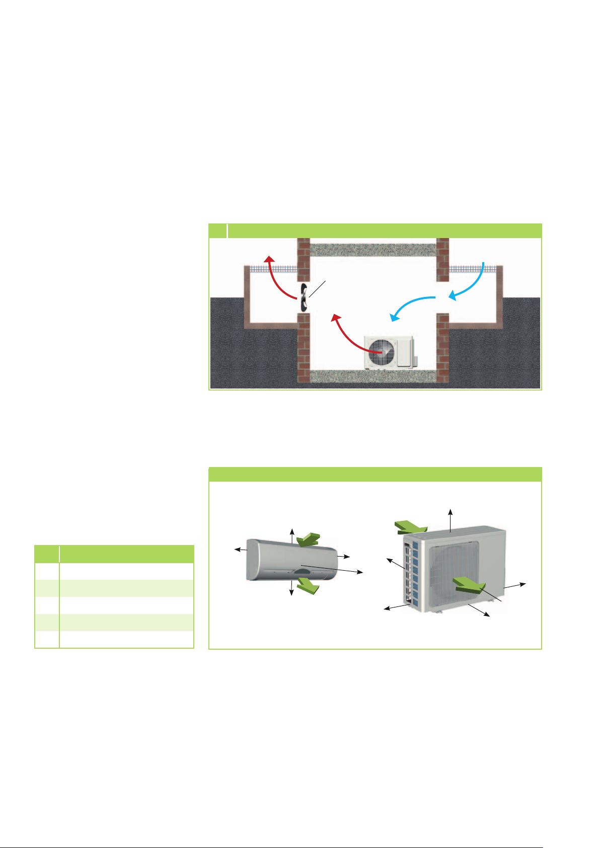
Minimum clearances
Observe the minimum clearances
to allow access for maintenance
and repair work and facilitate
optimum air distribution.
BL 261 AT, BL 351 AT
A 150 mm
B 700 mm
C 400 mm
D 150 mm
E 200 mm
Minimum clearances
120
120
200
Air intake
Air outlet
120
1500
Air intake
D
A
E
C
Air outlet
B
All dimensions are given in mm
18

Installation
Oil return measures
If the outdoor component is
installed at a higher level than
the indoor unit, suitable oil return
measures must be taken. Usually,
an oil pump bend is installed
for every 2.5 metres of height
difference.
Oil return measures
Outdoor component
Oil pump bend
in suction line
to outdoor
component one
every 2.5 metres of
height difference
Radius:
Min. 100 mm
Max. 2.5 m
Indoor unit
Connections
on the indoor unit
Connections
1
2
3
1 Outlet on the wall, right
2 Outlet through the wall, right
3 Outlet through the wall, right
4 Outlet on the wall, left
NOTE
Installation should only be
performed by authorised
specialists.
Unit installation
The indoor unit is attached by
means of a wall bracket, taking
into consideration the air discharge
side located in the lower part.
1. Mark the mounting points on
the structurally permissible
building sections according
to the dimensions of the wall
bracket.
2. If necessary, remove the break
out opening of the housing.
3. Connect the refrigerant pipes
to the indoor unit as described
below. The flexible refrigerant
pipe and the electrical control
cable are pre-installed.
4. Suspend the indoor unit on the
wall bracket by tilting it back
slightly and then by pressing
the bottom part of the unit
against the bracket (figure 5).
5. Check again that the unit is
level.
4
5
Connecting
Connection of
refrigerant pipes
The refrigerant pipes should be
connected by the customer on the
right-hand side of the outdoor
component.
1.
Use the wall or floor brackets to
fasten the outdoor component
where structurally allowed
(refer to the installation
instructions for the brackets).
2.
Ensure that structure-borne
sound is not transferred to
the building. Use vibration
dampers to reduce the effects
of structure-borne sound!
3.
Prepare the refrigerant pipes
for the outdoor component as
described above.
! ATTENTION
Both units are pre-filled with
refrigerant.
Suitable protective
clothing
must be worn during
installation
.
Extending the
refrigerant pipes
The 2 m refrigerant pipe contained
in the delivery may be extended by
3 metres or 8 metres.
1.
Remove the protective caps
from the quick connectors.
2. Connect the suitable pipes and
check their leak tightness after
connection.
Wall bracket
for indoor unit
The wall bracket for the unit must
be attached with suitable screws
and anchors.
! ATTENTION
Connection lines are filled with
refrigerant! Suitable protective
clothing must be worn during
installation
.
19

6 Remove the plastic cover
9
Connect the quick-release couplings
REMKO BL
Connection of quickrelease couplings
The refrigerant pipes should be
connected by the customer on the
right-hand side of the outdoor
component.
The pre-filled refrigerant pipes
are connected to the outdoor
component by means of the quickconnector system. Once installed,
the connections must be insulated
to prevent vapour diffusion.
The following instructions describe
the installation of the refrigerant
pipes of the indoor unit to the
outdoor component.
1. Remove the pre-installed
plastic cover from the outdoor
component (figure 6).
2. Remove the white protective
caps from the quick-connectors
on the outdoor component,
as well as the flexible
refrigerant pipes on the indoor
unit (figures 7 and 8).
7 Remove the protective caps
8 Remove the protective caps
11 Tightening fittings
Tighten
1st spanner
Counter with
2nd spanner
Tightening
torque:
1
4
“
3
8
“
1
2
“
5
8
“
3
4
“
NOTE
Only open the stop
cocks following complete
installation of the quickrelease couplings and
before turning on the system!
15-20 Nm
33-40 Nm
50-60 Nm
65-75 Nm
95-105 Nm
3. Before connecting the
refrigerant pipes, ensure that
the quick-release couplings are
situated in front of one another
(figure 9).
4. First connect and hand-tighten
the refrigerant pipes to ensure
they are correctly seated.
5. Then install the suction line
with the largest diameter
(figure 10).
6. Now fully tighten the fittings
using 2 suitably sized openended spanners. Use one
spanner to counter the force
when tightening the fitting
(figure 11).
7. Open the stop cocks before
turning on the system using an
Allen key!
10 Installation of suction line
Additional notes for installation
■
The flexible refrigerant pipes
supplied can be extended by
3 metres or 8 metres.
■
The flexible extension lines are
pre-filled with refrigerant.
NOTE
Installation should only
be performed by certified
specialists.
NOTE
Only use tools and
components designed for
refrigeration applications.
20

Leak testing
Once all the connections have
been made, the pressure gauge
station is attached to the Schrader
valve as follows (if fitted):
red = small valve
= injection pressure
blue = large valve
= suction pressure
Following connection of the quickrelease couplings, the connections
are checked using leak detection
spray and suitable devices for leaktightness. If leaks are found, the
connections have not been made
properly. Tighten the connection
or, if necessary, remove the quickrelease coupling and check for
contamination or damage.
Pumping down to
vacuum
! ATTENTION
Both units are pre-filled with
refrigerant. Pumping down to
vacuum is not required before
first commissioning.
The time required to generate the
vacuum is dependent on the
pipe volume of the indoor unit
and the length of the refrigerant
pipes. This always takes at least
60 minutes.
Once any foreign gases and
humidity have been completely
extracted from the system, the
valves on the pressure gauge
station are closed and the valves
on the outdoor component
are opened as described in the
"Commissioning" section.
! ATTENTION
A vacuum of min. 20 mbar
must be created!
Condensate draining and
ensured discharge
Condensate connection
If the temperature falls below the
dew point, condensation will form
on the finned condenser during
heating operation.
A condensate drip pan should be
installed on the underside of the
unit to drain any condensate.
■
The condensate drain pipe to
be installed on-site must be installed with a in cline of at least
2 % for good drainage.
If necessary, fit vapour density
insulation.
■
When operating the system at
outdoor temperatures below
4 °C, care must be taken that
the condensate line is frost
protected. The lower part of the
housing and condensate pan
are to be kept frost free in order
to ensure permanent drainage
of the condensate.
If necessary, fit supplementary
pipe heating.
■
After completed installation,
check that the condensate
drainage is unobstructed and
ensure that the line is leak tight.
Ensured discharge in the event of
leakage
Local regulations or environmental laws, for example the German
Water Resource Law (WHG), can
require suitable precautions to protect against uncontrolled draining
in case of leakage to provide for
safe disposal of escaping refrigerator oil or hazardous media.
10
Incline of the condensate line
minimum
2% incline
The condensate hose is designed
to be connected on the left-hand
side (as viewed from the front).
Electrical connection
A mains cable must be installed
as voltage supply and a control
cable to the indoor unit. The air
conditioning unit should be fused
in accordance with the technical
data. The pre-installed control
cable on the indoor unit must be
laid to the outdoor component.
! ATTENTION
All electrical installation
work should be performed
by specialist contractors.
Disconnect the power supply
when connecting the electrical
terminals.
■
We recommend installing
a main / repair switch on the
building close to the indoor
unit.
■
If an optionally available
condensation pump is used
on the unit, then an additional
relay for the shut-off contact
of the pump will be needed
to increase the switching power
to shut off the compressor.
21

REMKO BL
■
Control cables should be
screened if laid in areas exposed
to strong magnetic fields.
■
Details concerning the electrical
protection of the system are
provided in the technical data.
Connecting the indoor unit
2 a 10 m long control cable are
already connected to the indoor
unit. These control cables must be
laid to the outdoor component and
connected to the terminal block.
11
Connection of the indoor unit
Cover
Front terminal for
control cable to outdoor
component
Connection of the outdoor
component
Proceed as follows to connect the
cable:
1. Remove the cover from the
unit.
2. Remove the side panel next to
the terminals.
3. Feed the control cable through
the edge protection rings on
the fixed connection panel.
5. Insert the connector into the
corresponding socket.
6. Anchor the cable in the strain
relief and re-assemble the unit
(figure 12).
! ATTENTION
Check all plugged and clamped
terminals to verify they are
seated correctly and make
a permanent contact. Tighten
as required.
12
Connection of the outdoor component
22
Rear terminal for
electrical supply
Cover
Electrical connection diagram
Connection of BL 261, BL 351
rear
terminal
front
terminal
Indoor unit
L L L
N
PE
3
2
Outdoor component
Exterior conductor
Neutral conductor
Compressor contact (red)
Reverse flow valve (black)
Fan motor (white)
PE
3
2
11
Mains cable
230 V~,
50 Hz,
NN
L1 / N
/ PE
PE

Electrical drawings
BL 261, BL 351 IT
Exterior conductor
Neutral conductor
Earth conductor
Compressor (red)
Condenser fan (white)
Reverse flow valve (black)
L
N
3
1
2
AC-N
Transformer
Vaporiser fan motor
FM
AC-L
COMP
Probe vaporiser
Swing motor
SM
Display
Receiver
Probe air circulation
BL 261, BL 351 AT
Condenser fan (white)
Reverse flow valve (black)
Compressor (red)
Earth conductor
Neutral conductor
Exterior conductor
1
2
3
N
L
Reverse flow valve
BK
BU
BN
BU
WH
Compressor contact
Condenser fan
BK
S
Compressor
C
BU
R
Colour code
WH = white
BU = blue
BR = brown
BK = black
23

REMKO BL
Before
commissioning
Following a successful leak check,
the unit can be started again
without the pipes needing to be
pumped down to a vacuum.
Perform the following checks
prior to commissioning the unit
for the first time and after any
interventions affecting the cooling
circuit. Record the results in the
commissioning report:
■
Check and open shut-off valves
■
Check all refrigerant pipes and
valves using leak detection
spray or soapy water to ensure
they are tight and that the
suction and injection pipes have
not been accidentally confused
with the unit at a standstill.
Adding refrigerant
! ATTENTION
Wear protective clothing when
handling refrigerant.
The units contain a basic
quantity of refrigerant. Should
the refrigerant leak, remedy
the leak, pump the refrigerant
pipes down to a vacuum and refill
the basic quantity of refrigerant.
Refrigerant fill
quantity
Basic
line length
! ATTENTION
When filling the system with
refrigerant, ensure that it is
always in liquid form!
BL 261 BL 351
0.7 kg 1.0 kg
Commissioning
NOTE
Commissioning should only be
performed and documented
by specially trained personnel.
The system can be commissioned
once all the components have
been connected and tested.
A functional check should be
performed to verify its correct
function and identify any unusual
operational behaviour prior to
handing it over to the operator.
Functional checks and
test run
Check the following points:
■
Check the refrigerant lines and
insulation for damage.
■
Check the electrical connection
between the indoor unit and
the outdoor component for
correct polarity.
■
Check that all fastenings,
mountings etc. are firm and at
the correct level.
24
NOTE
Check overheating to
determine the refrigerant fill
quantity.
NOTE
The escape of refrigerant contributes to climatic change. In
the event of escape, refrigerant
with a low greenhouse potential has a lesser impact on global warming than those with a
high greenhouse potential.
This device contains refrigerant with a greenhouse potential of 1975. That means the
escape of 1 kg of this refrigerant has an effect on global
warming that is 1975 times
greater than 1 kg CO2, based
on 100 years. Do not conduct
any work on the refrigerant
circuit or dismantle the device - always enlist the help of
qualified experts.
■
Leak tightness of refrigerant
pipes.
■
Compressor and fan running
smoothly.
■
In cooling mode, cold air
output by the indoor unit, and
warm air output by the outdoor
component.
■
Functional test of the indoor
unit and all program sequences.
■
Check of the surface
temperature of the suction
line and check vaporiser is
not overheating. To measure
the temperature, hold the
thermometer to the suction
line and subtract the boiling
point temperature reading on
the pressure gauge from the
measured temperature.
■
Record the measured
temperatures in the
commissioning report.

Function test of the cooling
and heating modes
1. Remove the protective caps
from the valves.
2. Start the commissioning
procedure by briefly opening
the shut-off valves on the
outdoor component until
the pressure gauge indicates
a pressure of approx. 2 bar.
3. Use leak detection spray or
suitable devices to check that all
the connections are tight.
4. If no leaks are found, fully open
the shut-off valves by turning
them anti-clockwise using a
spanner. If leaks are found,
remedy the faulty connection.
It is imperative that the vacuum
creation and drying steps are
repeated!
9. Check the correct function
of the condensate line by
pouring distilled water into the
condensation tray.
A bottle with a spout is
recommended for pouring the
water into the condensation
tray.
10.
Switch the indoor unit to
cooling mode.
11.
Check the correct function
and settings of all regulation,
control and safety devices
during the test run.
12.
Check the control system in the
indoor unit using the functions
described in the Operating
Manual.
Timer, temperature settings and
all mode settings.
13.
Check the overheating,
outdoor, indoor, outlet and
vaporisation temperatures and
record the measures values in
the commissioning report.
Final tasks
■
Reassemble all disassembled
parts.
■
Familiarise the operator with
the system.
NOTE
Check that the shut-off
valves and valve caps are
tight after carrying out any
work on the cooling circuit.
Use appropriate sealant
products as necessary.
5. Switch off the main circuit
breaker or remove the fuse (to
be provided by the customer).
6. Use the remote control to
switch on the unit and select
the cooling mode, maximum
fan speed and lowest target
temperature.
7. Measure and record all
the required values in the
commissioning report and
check the safety functions.
8. Check the indoor unit control
system using the functions
described in the "Operation"
section. Timer, temperature
setting, fan speeds and
switching to ventilation or
dehumidification mode.
14.
Switch the indoor unit to
heating mode.
15.
Check the functionality of all of
the previously described safety
devices and during the test run.
16.
Record the measured values in
the commissioning report.
17.
Remove the pressure gauge.
Check that seals have been
fitted in the sealing caps.
25

REMKO BL
Unit dimensions
BL 261, BL 351 AT
BL 261, BL 351 IT
780
790
275
250
510
540
280
200
All dimensions are given in mm
We reserve the right to modify the dimensions and constructional design as part of the ongoing technical development process.
26

Exploded view of BL 261 IT, BL 351 IT
11
10
8
12
Spare parts list
7
5
and constructional design as part of the ongoing technical development process.
2
We reserve the right to modify the dimensions
9
1
6
4
3
No. Designation BL 261 IT BL 351 IT
From serial number 801D51-... 807D51-...
1 Front panel, complete 1109400 1109413
2 Air filter, set 1109453 1109414
3 Circuit board, display 1109402 1109415
4 Swing motor 1109403 1109416
5 Air outlet fins, set 1109404 1109417
6 Condensation tray 1109405 1109418
7 Vaporiser 1109454 1109459
8 Fan wheel 1109407 1109420
9 Fan motor 1109455 1109421
10 Control board 1109480 1109481
11 Transformer 1109410 1109423
12 IR remote control 1109411 1109424
Spare parts not illustrated
Probe air circulation / vaporiser 1109412 1109425
Injection pipe quick-release couplings 1109457 1107873
Suction line quick-release couplings 1109458 1107874
When ordering spare parts, please state the EDP no., unit number and unit type (see identification plate)!
27

REMKO BL
Exploded view of BL 261 AT, BL 351 AT
8
9
4
3
2
13
7
12
5
1
6
10
11
Spare parts list
No. Designation
From serial number 801D81-... 807D81-...
1 Front panel 1107885 1107886
2 Fan blade, condenser 1107864 1107864
3 Fan motor, condenser 1107865 1107865
4 Finned condenser 1107936 1107937
5 Cover panel 1107934 1107935
6 Side panel, right 1107932 1107933
7 Compressor, complete 1107866 1107867
8 Condenser, compressor 1107807 1107820
9
Condenser, condenser fan
10 Shut-off valve, suction line 1107809 1107822
11 Shut-off valve, injection pipe 1107810 1107823
12 Compressor contact 1107811 1107824
13 Reverse flow valve 1107812 1107825
Spare parts not illustrated
Injection pipe quick-release coupling 1107878 1107871
Suction line quick-release coupling 1107879 1107872
When ordering spare parts, please state the EDP no., unit number and type of unit (see identification plate)!
28
BL 261 AT BL 351 AT
1107808 1107821

Technical data
Series BL 261 BL 351
Operating mode Wall / room air conditioner combination for cooling and heating
Nominal cooling output
Nominal heating output
Energy efficiency rating, cooling
Energy efficiency ratio EER
Energy efficiency rating, heating
Energy efficiency ratio COP
Power consumption, yearly, (500h) C/H kWh 405 / 400 555 / 580
Operating range (room volume), approx. m³ 80 110
Refrigerant R 410A
Operating pressure, max. kPa 4200 / 4200
Power supply V/Hz 230 / 1~ / 50
Nom. electrical power consumption, cooling
Electrical rated power consumption, heating
Electrical rated power consumption, cooling
Electrical rated power consumption, heating
Electr. starting current, max. A 21 28
Max. operating pressure kPa 4200 / 4200
Data specific to indoor unit
Adjustment range, room temperature °C +16 to +31
Operating range °C +15 to +31
Air flow volume per speed setting m³/h 320/370/420 380/450/520
Sound pressure level per speed setting
Protection class IP X0
Condensate draining mm 17 17
Dimensions - height mm 275 275
width mm 790 790
depth mm 200 200
Weight kg 8,0 10,0
Data specific to outdoor component
Operating range, cooling °C +7 to +48
Operating range, heating °C -7 to +25
Air flow rate, max. m³/h 1925 2050
Protection class IP 24
Sound pressure level, max.
Refrigerant, basic capacity kg 0.70 1.00
Refrigerant pipe, length approx.
series / accessories
Refrigerant pipe, height, max. m 5
Dimensions - height mm 540 540
width mm 780 780
depth mm 250 250
Weight kg 30,0 34,0
Serial number 801... 807...
EDP no. 1630365 1630360
1) Air inlet temperature TK 27°C / FK 19°C, outdoor temperature TK 35°C, FK 24°C, max. air flow rate
2) Air inlet temperature TK 20°C, outdoor temperature TK 7°C / FK 6°C, max. air flow rate
3) Distance 1m free field
4) Contains greenhouse gas according to Kyoto protocol
1)
2)
1)
1)
2)
2)
kW 2.69 3.59
kW 2.96 4.24
A A
3.32 3.23
A A
3.70 3.66
1)
kW 0.81 1.11
2)
kW 0.80 1.16
1)
2)
A 3.60 4.99
A 3.61 5.32
4)
BL 261 IT BL 351 IT
3)
dB(A) 30/34/38 32/36/40
BL 261 AT BL 351 AT
3)
dB(A) 52 53
m 2 / 10
29

EC – Declaration of Conformity
in accordance with the Machinery Directive, Annex II 1A
Original Declaration of Conformity
We hereby declare that the devices named below, produced and sold by us, satisfy the relevant
basic requirements of the EC guidelines, the EC safety standards and other product-specific EC
standards.
Name of Manufacturer: REMKO GmbH & Co. KG
Klima- und Wärmetechnik
Im Seelenkamp 12
D - 32791 Lage
Name of the CE representative: REMKO GmbH & Co. KG
Klima- und Wärmetechnik
Im Seelenkamp 12
D - 32791 Lage
Equipment (machinery) - Implementation:
design with quick-release coupling system
Series / Designation: REMKO B
Series / Class Number: 801..., 807...
Applicable regulations:
MA - RL 2006/42/EG Machinery Directive
NS - RL 2006/95/EG Low-voltage directive
EMV – RL 2004/108 EWG EMC Directive
EnVKV - RL 92/75/EWG Energy Consumption Labelling Directive
EG 97/23/EG Pressure Equipment Directive
Applicable Standards:
DIN EN ISO 12100-1-2 : 2004-04; DIN EN ISO 13857,
EN 14511 T1-4;
DIN 45635 - 1;
EN 378 – 1-4;
EN 55014 - 1; EN 55014 - 2; EN 55104
EN 60204 - 1; EN 60335 - 1; EN 60335 - 2 - 40;
EN 61000 - 3 - 2; EN 61000 - 3 - 3;
Wall - room air conditioner combination in split
L 261, BL 351
Lage, 22 January 2010 REMKO GmbH & Co. KG
..............................................
Signature, Product Manager


REMKO INTERNATIONAL
... and also right in your neighbourhood!
Benefit from our experience and advice
REMKO GmbH & Co. KG
Klima- und Wärmetechnik
Im Seelenkamp 12 D-32791 Lage
Postfach 1827 D-32777 Lage
Telephone +49 5232 6 06-0
Fax +49 5232 606-2 60
E-mail info@remko.de
Internet www.remko.de
Hotline
Air conditioning and
heating technology
+49 5232 606-0
Export
+49 5232 606-130
Consultation
Thanks to intensive training,
our consultants are always
completely up-to-date when
it comes to technical expertise.
This has given us the reputation
of being more than just an
excellent, reliable supplier:
REMKO, a partner, who helps
to solve problems.
Sales
REMKO offers not just a well
established sales network both
nationally and internationally,
but also has exceptionally highly-
qualified sales specialists.
REMKO field staff are more than
just sales representatives: above
all, they must advise our clients
in the areas of air conditioning
and heating technology.
Customer service
Our equipment operates
precisely and reliably. However,
in the event of a fault, REMKO
customer service is quickly on the
scene. Our comprehensive
network of experienced dealers
guarantees quick and reliable
service.
We reserve the right to make technical changes, and provide no warranty as to the accuracy of this data!
 Loading...