


FX-1
Randell FX-1, FX-1CS, FX-2CS, FX-2WS, FX-3SS Service Manual
...
OPERATOR’S MANUAL
This manual provides information on
installation, operating, maintenance,
trouble shooting & replacement
parts for
Refrigerated Solutions with
FlexiCold Technology
FX
FX----1111
FXFX
2N1 – TWO COOLING SYSTEMS IN ONE
Refrigerator (40°F)
• Freezer (-5°F)
• Or anywhere in between (-5° to 40°F)
FX
FX1111----4444NNNN1111
FXFX
4N1 – FOUR COOLING SYSTEMS IN ONE
• Refrigerator (40°F)
• Freezer (-5°F)
• Or anywhere in between (-5° to 40°F)
• Rapid Chiller for on-demand blast
chilling
• Safety Thaw for on-demand thawing of
frozen food safely
NOTIFY CARRIER OF DAMAGE AT ONCE.
It is the responsibility of the consignee to inspect
the container upon receipt of same and to
determine the possibility of any damage, including
concealed damage. Randell suggests that if you
are suspicious of damage to make a notation on
the delivery receipt. It will be the responsibility of
the consignee to file a claim with the carrier. We
recommend that you do so at once.
Manufacture Service/Questions 888-994-7636.
Information contained in this document is known to be
current and accurate at the time of printing/creation.
Unified Brands recommends referencing our product line
websites, unifiedbrands.net, for the most updated
product information and specifications.
1055 Mendell Davis Drive
Jackson, MS 39272
888-994-7636 • Fax 888-864-7636
randellfx.com
12/12/2007
PP MNL0705-REV B

2222
888-994-7636

Table of Contents
page 2………………….….Table of Contents & Congratulations
page 3……..Serial Number Location & Parts & Service Hotline
page 4-8………………………………....Randell Limited Warranty
page 9-10..………………………………………Unit Specifications
page 11-12..…………………………………………Unit Installation
page 13………………………………..Gasket Sealing Adjustment
page 14...………………………..…….…FX-1(2N1) Unit Operation
page 15………………………………FX-1(2N1) Control Operation
page 16-17..…………………………...FX-1(2N1) Control Settings
page 18…………………….......FX-1(2N1)Control LED Functions
page 19……………….....FX-1(2N1) Control Setting Instructions
page 20-24……………………….…....FX1-4N1 Control Operation
page 25-27………………………….……FX1-4N1 Control Settings
page 28……………………….….FX1-4N1 Control LED Functions
page 29-34……………………….………..FX1-4N1 Unit Operation
page 29-32……FX1-4N1 Rapid Chill Operation
page 33-34…..FX1-4N1 Rapid Thaw Operation
page 35-36……………………….…..…..Preventive Maintenance
page 37……………………………...FX-1(2N1) Electrical Diagram
page 38…………………………....…..FX1-4N1 Electrical Diagram
page 39…………………………....…………..……Troubleshooting
page 40-42…………………........…FX-1(2N1) Replacement Parts
page 43-47………………………...…FX1-4N1 Replacement Parts
page 48-49………………………...…..…FX Series Optional Parts
Congratulations
welcome to the growing family of satisfied Randell customers.
Our reputation for superior products is the result of consistent quality craftsmanship. From the
earliest stages of product design to successive steps in fabrication and assembly, rigid standards
of excellence are maintained by out staff of designers, engineers, and skilled employees.
Only the finest heavy-duty materials and parts are used in the production of Randell brand
equipment. This means that each unit, given proper maintenance will provide years of trouble free
service to its owner.
on your recent purchase of Randell food service equipment, and
randellfx.com
3333

In addition, all Randell food service equipment is backed by
some of the best warranties in the food service industry and by
our professional staff of service technicians.
Retain this manual for future reference.
NOTICE: Due to a continuous program of product improvement, Randell
reserves the right to make changes in design and specifications without prior
notice.
NOTICE: Please read the entire manual carefully before installation. If certain
recommended procedures are not followed, warranty claims will be denied.
MODEL NUMBER _________________________
SERIAL NUMBER _________________________
INSTALLATION DATE _____________________
The serial number is located in the cabinet left side wall. Removal of the
insulated insert from the drawer will be nessecary to view data plate.
Randell Service and Parts
800-621-8560
Hotline
4444
888-994-7636

Warranty Policies
Congratulations on your purchase of a Randell Manufactured piece of equipment.
Randell believes strongly in the products it builds and backs them with the best
warranty in the industry. Standard with every unit is the peace of mind that this unit
has been thoroughly engineered, properly tested and manufactured to excruciating
tolerances, by a manufacturer with over 30 years of industry presence. On top of
that front end commitment, Randell has a dedicated staff of certified technicians
that monitor our own technical service hotline at 1-800-621-8560 to assist you with
any questions or concerns that may arise after delivery of your new Randell
equipment.
PARTS WARRANTY
1. One year parts replacement of any and all parts that are found defective in
material or workmanship. Randell warrants all component parts of
manufactured new equipment to be free of defects in material or workmanship,
and that the equipment meets or exceeds reasonable industry standards of
performance for a period of one year from the date of shipment from any
Randell factory, assembly plant or warehouse facility.
NOTE: warranties are effective from date of shipment, with a thirty day
window to allow for shipment, installation and set-up. In the event
equipment was shipped to a site other than the final installation site,
Randell will warranty for a period of three months following installation,
with proof of starting date, up to a maximum of fifteen months from the
date of purchase.
2. Free ground freight of customer specified location for all in warranty parts
within continental U.S. Component part warranty does not cover glass
breakage or gasket replacement. Randell covers all shipping cost related to
component part warranty sent at regular ground rates (UPS, USPS). Freight
or postage incurred for any express or specialty methods of shipping are
the responsibility of the customer.
LABOR COVERAGE
In the unlikely event a Randell manufactured unit fails due to defects in
materials or workmanship within the first ninety days, Randell agrees to pay
the contracted labor rate performed by an Authorized Service Agent (ASA).
Any work performed by a non-ASA will not be honored by Randell. Please
consult Randell Technical Support (800-621-8560) for a complete listing of
ASAs or visit the service page of our website: www.unifiedbrands.net.
Warranties are effective from date of shipment, with a thirty day window to
allow for shipment, installation and setup. Where equipment is shipped to any
site other than final installation, Randell will honor the labor warranty for a
period of ninety days following installation with proof of starting date, up to a
maximum of six months from date of purchase.
randellfx.com
5555

Warranty Policies con’t
Temperature adjustments are not covered under warranty, due to the wide
range of ambient conditions.
WHEN OPTIONAL 5 YEAR COMPRESSOR WARRANTY APPLIES
1. Provide reimbursement to an ASA for the cost of locally obtained
replacement compressor in exchange for the return of the defective
compressor sent back freight prepaid. Note: Randell does limit
amount of reimbursement allowed and does require bill from local
supply house where compressor was obtained (customer should not
pay servicing agent up front for compressor).
2. Provide repair at the manufacturing facility by requiring that the
defective unit be sent back to Randell freight prepaid. Perform repair at
the expense of Randell and ship the item back to the customer freight
collect.
3. Furnish complete condensing unit freight collect in exchange for the
return of the defective compressor sent back freight prepaid.
(Decisions on whether or not to send complete condensing units will be
made by Randell’s in-house service technician).
WHEN OPTIONAL LABOR EXTENSION POLICY APPLIES
Randell will provide reimbursement of labor to an ASA for any customer that
has an optional labor extension of our standard warranty. (Contracted rates do
apply) Randell offers both 1 and 2 year extensions. Labor extensions begin at
the end of our standard warranty and extend out 9 months to 1 calendar year
or 21 months to 2 calendar years from date of purchase. Please contact
Randell Manufacturing’s technical service hotline at 1-800-621-8560 for details
and any question on Authorized Service Agents (ASA).
WHEN EXPORT WARRANTIES APPLY
1. Randell Manufacturing covers all non-electrical components under the
same guidelines as our standard domestic policy.
2. All electrical components operated on 60 cycle power are covered
under our standard domestic policy.
3. All electrical components operated on 50 cycle power are covered for
90 days from shipment only.
4. Extended warranty options are not available from the factory.
6666
888-994-7636

Warranty Policies con’t
ITEMS NOT COVERED UNDER WARRANTY
1. Maintenance type of repairs such as condenser cleaning, temperature
adjustments, clogged drains and unit leveling.
2. Randell does not cover gaskets under warranty. Gaskets are a
maintenance type component that are subject to daily wear and tear
and are the responsibility of the owner of the equipment. Because of
the unlimited number of customer related circumstances that can cause
gasket failure all gasket replacement issues are considered nonwarranty. Randell recommends thorough cleaning of gaskets on a
weekly basis with a mild dish soap and warm water. With proper care
Randell gaskets can last up to two years, at which time we recommend
replacement of all gaskets on the equipment for the best possible
performance.
NOTICE: FOOD LOSS IS NOT COVERED UNDER WARRANTY
3. Repairs caused by abuse such as broken glass, freight damage, or
scratches and dents.
4. Electrical component failure due to water damage from cleaning
procedures.
QUOTATIONS
Verbal quotations are provided for customer convenience only and are
considered invalid in the absence of a written quotation. Written quotations
from Randell are valid for 30 days from quote date unless otherwise specified.
Randell assumes no liability for dealer quotations to end-users.
SPECIFICATION & PRODUCT DESIGN
Due to continued product improvement, specification and product design may
change without notice. Such revisions do not entitle the buyer to additions.
Changes or replacements for previously purchased equipment.
SANITATION REQUIREMENTS
Certain areas require specific annotation requirements other than N.S.F. &
U.L. standards. Randell must be advised of these specifications before
fabrication of equipment. In these special circumstances, a revised quotation
may be required to cover additional costs. Failure to notify Randell before
fabrication holds the dealer accountable for all additional charges.
CANCELLATIONS
Orders canceled prior to production scheduling entered into
engineering/production and cancelled are subject to a cancellation charge
(contact factory for details).
randellfx.com
7777

Warranty Policies con’t
STORAGE CHARGES
Randell makes every effort to consistently meet our customer’s shipment
expectations. If after the equipment has been fabricated, the customer
requests delay in shipment, and warehousing is required:
1. Equipment held for shipment at purchasers request for a period of 30
days beyond original delivery date specified will be invoiced and
become immediately payable.
2. Equipment held beyond 30 days after the original delivery date
specified will also include storage charges.
SHIPPING & DELIVERY
Randell will attempt to comply with any shipping, routing or carrier request
designated by dealer, but reserves the right to ship merchandise via any
responsible carrier at the time equipment is ready for shipment. Randell will
not be held responsible for any carrier rate differences; rate differences are
entirely between the carrier and purchaser. Point of shipping shall be
determined by Randell (Weidman, MI/Tucson, AZ/Jackson, MS). At dealer’s
request, Randell will endeavor whenever practical to meet dealer’s request.
Freight charges to be collect unless otherwise noted.
DAMAGES
All crating conforms to general motor carrier specifications. To avoid
concealed damage, we recommend inspection of every carton upon receipt.
In the event the item shows rough handling or visible damage to minimize
liability, a full inspection is necessary upon arrival. Appearance of damage will
require removing the crate in the presence of the driver. A notation must be
placed on the freight bill and signed for by the truck driver at the time of
delivery. Any and all freight damage that occurs to a Randell piece of
equipment as a result of carrier handling is not considered under warranty, and
is not covered under warranty guidelines. Any freight damage incurred during
shipping needs to have a freight claim filed by the receiver with the shipping
carrier. Consignee is responsible for filing of freight claims when a clear
delivery receipt is signed. Claims for damages must be filed immediately
(within 10 days) by the consignee with the freight carrier and all cartons and
merchandise must be retained for inspection.
8888
888-994-7636

Warranty Policies con’t
RETURNED GOODS
Authorization for return must first be obtained from Randell before returning
any merchandise. Any returned goods shipment lacking the return
authorization number will be refused, all additional freight costs to be borne by
the returning party. Returned equipment must be shipped in original carton,
freight prepaid and received in good conditions. Any returned merchandise is
subject to a minimum handling charge (consult factory for rate).
INSTALLATION
Equipment installation is the responsibility of the dealer and/or their customer.
Randell requires all equipment to be professionally installed.
PENALTY CLAUSES
Dealer penalty clauses, on their purchase order or contractually agreed to
between the dealer and their clients are not binding on Randell. Randell does
not accept orders subject to penalty clauses. This agreement supersedes any
such clauses in dealer purchase orders.
*FOOTNOTES IN REFERENCE TO PARAGRAPHS ABOVE
1. Herein called Randell.
2. NET means list price less discount, warranty, labor policy, freight, Randell delivery and other
miscellaneous charges.
CASH DISCOUNTS WILL BE CALCULATED ON NET ONLY.
randellfx.com
9999
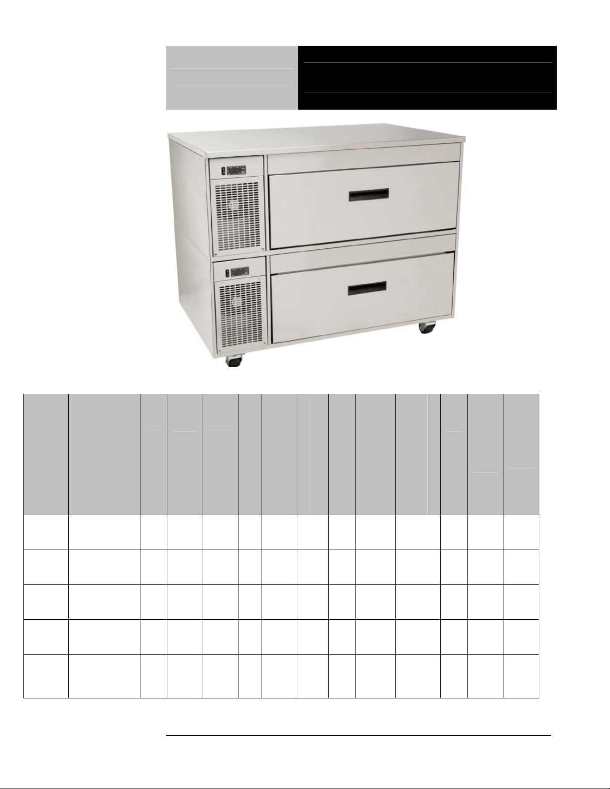
Unit Specifications
Model Description
FLEXICOLD 1
FX-1
FX-1CS
FX-2CS
FX-2WS
FX-3SS
SECTION
SYSTEM 2N1
BASE MODEL
FLEXICOLD 1
SECTION 2N1
EQUIPMENTTOP SYSTEM
FLEXICOLD 2
SECTION 2N1
EQUIPMENTTOP SYSTEM
FLEXICOLD 2
SECTION 2N1
PREP WORKTOP SYSTEM
FLEXICOLD 3
SECTION 2N1
PRECISION
STORAGE
SYSTEM
Model FX-2WS Double Flexi-Cold Drawer
L
E
N
G
T
H
46” 29.6” 16.4" 1 3.0 6.1cc 3.9 1.22kw 1.99kw 115 5-15p 245
48" 33" 24" 1 3.0 6.1cc 3.9 1.22kw 1.99kw 115 5-15p 385
96" 33" 24" 2 6.0
46” 29.6" 37.3" 2 6.0
46” 29.6" 53.7" 3 9.0
D
E
P
T
H
H
E
G
H
T
D
R
A
I
W
E
R
S
CUBIC FEET OF STORAGE
COMPRESSOR SIZE
6.1cc
each
6.1cc
each
6.1cc
each
ACTUAL AMP DRAW
7.8 2.44kw 3.98kw 115 5-15p 770
7.8 2.44kw 3.98kw 115 5-15p 635
11.7 3.66kw 5.97kw 115 5-15p 891
(REFRIGERATOR)
POWER USAGE (PER DAY)
POWER USAGE (PER DAY)
V
O
L
T
S
(FREEZER)
N
E
M
A
SHIP
WT.
lbs
10
10
888-994-7636
1010

Model Description
FLEXICOLD 1
SECTION
FX1-4N1
FX1-
4N1CS
FX2-
4N1CS
FX2-
4N1CSL
FX2-
4N1CSR
FX2-
4N1WS
FX2-
4N1WST
FX2-
4N1WSB
FX3-
4N1SST
FX3-
4N1SSTC
SYSTEM 4N1
BASE
MODEL
FLEXICOLD 1
SECTION 4N1
EQUIPMENTTOP SYSTEM
FLEXICOLD 2
SECTION 4N1
EQUIPMENTTOP SYSTEM
FLEXICOLD 2
SECTION
COMBO
EQUIPMENTTOP SYSTEM
4N1 LF 2N1
RT
FLEXICOLD 2
SECTION
COMBO
EQUIPMENTTOP SYSTEM
2N1 LF 4N1
RT
FLEXICOLD 2
SECTION 4N1
PREP WORKTOP SYSTEM
FLEXICOLD 2
SECTION
COMBO
PREP WORKTOP SYSTEM
4N1 TOP
FLEXICOLD 2
SECTION
COMBO
PREP WORKTOP SYSTEM
4N1 BOTTOM
FLEXICOLD 3
SECTION
COMBO
PRECISION
STORAGE
SYSTEM 4N1
TOP
FLEXICOLD 3
SECTION
COMBO
PRECISION
STORAGE
SYSTEM 4N1
TOP 2
S
G
H
L
D
E
E
N
P
T
T
H
H
E
G
H
T
E
C
I
T
I
O
N
S
COMPRESSOR SIZE
ACTUAL AMP DRAW
CUBIC FEET OF STORAGE
(REFRIGERATOR)
POWER USAGE (PER DAY)
(FREEZER)
POWER USAGE (PER DAY)
POWER USAGE
(PER 4 HOUR BLAST CHILLER CYCLE
EACH UNIT)
POWER USAGE
(PER 6 HOUR RAPID THAW CYCLE
V
O
L
T
S
N
E
M
A
SHIP
WT.lbs
EACH UNIT)
46” 29.6” 16.4" 1 3.0 8.8cc 6.3 1.22 kw 1.99 kw 2.1 kw 1.4 kw 115 5-15p 250
48" 33" 24" 1 3.0 8.8cc 6.3 1.22 kw 1.99 kw 2.1 kw 1.4 kw 115 5-15p 390
96" 33" 24" 2 6.0
8.8cc
each
6.3
2.44 kw 3.98 kw 2.1 kw 1.4 kw
ea.
115
ea.
(2)
5-15p
780
(1)
8.8cc
96" 33" 24" 2 6.0
10.2 2.44 kw 3.98 kw 2.1 kw 1.4 kw 115 5-15p 780
(1)
6.1cc
(1)
96" 33" 24" 2 6.0
6.1cc
(1)
8.8cc
10.2 2.44 kw 3.98 kw
2.1
kw
1.4 kw 115 5-15p 780
46” 29.6" 37.3" 2 6.0
8.8cc
each
6.3
2.44 kw 3.98 kw
ea.
2.1
kw
1.4 kw
115
ea.
(2)
5-15p
645
(1)
46” 29.6" 37.3" 2 6.0
8.8cc
(1)
6.1cc
10.2 2.44 kw 3.98 kw
2.1
kw
1.4 kw 115 5-15p 645
(1)
46” 29.6" 37.3" 2 6.0
6.1cc
(1)
8.8cc
10.2 2.44 kw 3.98 kw
2.1
kw
1.4 kw 115 5-15p 645
(1)
(2)
6.3
&
3.66 kw 5.97 kw
7.8
2.1
kw
1.4 kw
115
ea.
(2)
5-15p
905
46” 29.6" 53.7" 3 9.0
8.8cc
6.1cc
(2)
(1)
6.3
&
3.66 kw 5.97 kw
10.2
2.1
kw
1.4 kw
115
ea.
(2)
5-15p
905
46” 29.6" 53.7" 3 9.0
8.8cc
6.1cc
randellfx.com
11
11
1111

Unit Installation
SELECTING A LOCATION FOR YOUR NEW UNIT
The following conditions should be considered when selecting a location for your
unit:
1. Floor Load: The area on which the unit will rest must be level, free of
vibration, and suitably strong enough to support the combined weights
of the unit plus the maximum product load weight
2. Clearance: Clearance for opening the drawer and access to its
contents is the only requirements. Do not place any object that can
block the ventilation exhaust from the machine compartment register.
3. Ventilation: The air cooled self contained unit requires a sufficient
amount of cool clean air. Avoid surrounding your equipment stand
around other heat generating equipment and out of direct sunlight.
Also, avoid locating in an unheated room or where the room
temperature may drop below 55° F or above 90° F.
INSTALLATION CHECKLIST
After the final location has been determined, refer to the following checklist prior to
start-up:
1. Check all exposed refrigeration lines to ensure that they are not kinked,
dented, or rubbing together.
2. Check that the condenser and evaporator fans rotate freely without
striking any stationary members.
3. Unit must be properly leveled; check all legs or casters to ensure they
all are in contact with the floor while maintaining a level work surface.
Adjusting bullet feet heights or shimming casters may be necessary if
the floor is not level.
followed. Randell is not responsible for damage to equipment if
improperly installed.
4. Plug in unit and turn on main on/off power switch. The main power
switch is located in the front panel next to the digital control
5. Allow unit time to cool down to temperature. If temperature adjustments
are required, the temperature control is located on the front panel.
Confirm that the unit is holding the desired temperature.
6. Refer to the front of this manual for serial number location. Please
record this information in your manual on page 3 now. It will be
necessary when ordering replacement parts or requesting warranty
service.
7. Before putting in food, allow your unit to operate for approximately (1)
hour so that interior of the unit is cooled down to storage temperature.
NOTE: All motors are oiled and sealed.
NOTE: FAILURE TO FOLLOW INSTALLATION GUIDELINES AND
RECOMMENDATIONS MAY VOID THE WARRANTY ON YOUR UNIT.
NOTE: Damage to equipment may result if not
12
12
888-994-7636
1212

Unit Installation con’t
ELECTRICAL SUPPLY: Any wiring should be done by a qualified electrician in
accordance with local electrical codes. A properly wired and grounded outlet will
assure proper operation. Please consult the data tag attached to the compressor
to ascertain the correct electrical requirements. Supply voltage and amperage
requirements are located on the serial number tag located inside the mechanical
housing.
NOTE: It is important that a voltage reading be made at the compressor
motor electrical connections, while the unit is in operation to verify the
correct voltage required by the compressor is being supplied. Low or high
voltage can detrimentally affect operation and thereby void its warranty.
NOTE: it is important that your unit has its own dedicated line. Condensing
units are designed to operate with a voltage fluctuation of plus or minus 10%
of the voltage indicated on the unit data tag. Burn out of a condensing unit
due to exceeding voltage limits will void the warranty.
randellfx.com
13
13
1313
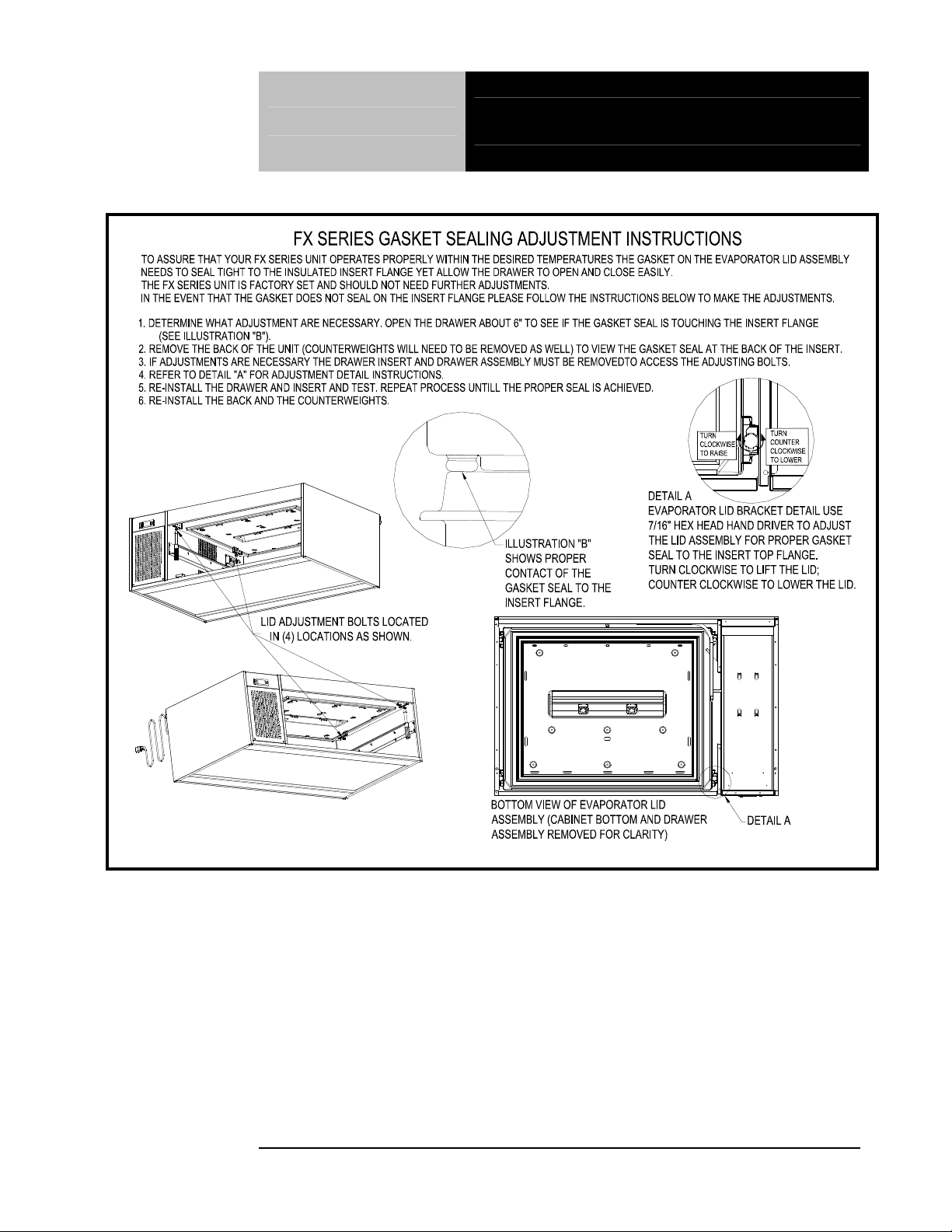
Gasket Sealing Adjustment
14
14
888-994-7636
1414

FX-1 (2N1) Unit Operation
PRODUCT PLACEMENT AND MAXIMUM LOAD LEVELS
1. This unit’s insulated drawer insert is provided and designed to
hold food products with or without containers.
2. Refrigerated or freezer tempered air is introduced into the
insulated drawer insert from above and circulates around the
product for even temperature distribution.
3. For the unit to operate at full efficiency the drawer seals
should be maintained in good condition. It is essential that
product is not stored above the Max Fill line as this can
damage the seals and affect the operation of the unit.
4. This unit is designed for holding products at temperatures -5°F
to 40°F. Products placed in unit should be pre-chilled to the
holding temperature. This unit is not intended for use as a pull
down cabinet.
5. The unit is capable of storing any food product. However,
products which may give off acidic odors like vinegar, onions,
etc should be suitably sealed. Randell also recommends
containers with liquid food products be stored with lids.
6. The drawer system is designed for easy unobstructed access to
the product in the insulated drawer insert. The track should run
smoothly with little resistance during the motion of opening and
closing the drawer. The drawer will have more resistance when
the unit is warm and not operating in either the refrigeration or
freezer mode, this is normal as the gasket will contract slightly
when the unit is cooling and allow smooth travel of the drawer.
randellfx.com
15
15
1515
louvered panel.
Figure 2
AMBIENT CONDITIONS
1. This unit is designed for operation in a room ambient of 86°F / 55% relative humidity. It should
never be used outside or located in direct sunlight.
Randell has attempted to preset the temperature control to ensure that your unit runs at an optimum
temperature, but due to varying ambient conditions, including elevation, food type and your type of
operation, you may need to alter this temperature.
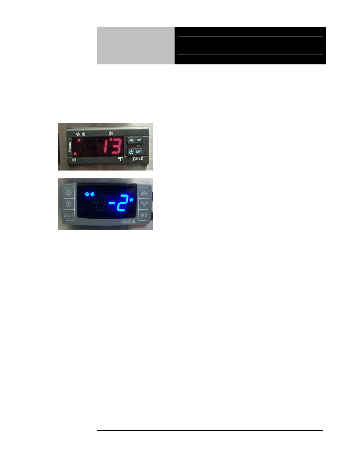
Your FX-1 (2N1) Series Unit is equipped with an
electronic temperature control. Figure 1, left, illustrates
the Dixell XR60C control location on the front above the
FX-1 (2N1) Control Operation
Figure 1
, left, illustrates an alternate electronic
temperature control, Dixell XR60CX with blue LED.
Before making temperature adjustments:
A. Allow adequate time for the cabinet temperature to equalize. When initially started or when
first loaded, it can take a long time for temperatures in the display area to stabilize.
B. Make sure that unit operation is not being effected by room ambient conditions. (See Ambient
Conditions section above). If there are any significant ambient issues, adjusting the temperature
setting may not help.
To raise temperature:
A. Push and hold the “SET” button until set point 33 appears then release the “SET” button.
33 is the current set point temperature.
B. Push and release the up arrow 1 or more times until the desired temperature is displayed.
Push and release the “SET” button one time. The new set point will flash 3 times and then
will be locked in.
To lower temperature:
A. Push and hold the “SET” button until 33 appears and then release the “SET” button. 33 is
the current set point temperature.
B. Push and release the up arrow 1 or more times until the desired temperature is displayed.
Push and release the “SET” button one time. The new set point will flash 3 times and then
will be locked in.
NOTE: The FX-1 (2N1) Series Unit is designed to operate in both refrigerated or freezer
mode by adjusting the “SET” point to the desired temperature. The maximum highest
setting is 40°F and the minimum lowest setting is -5°F. If the settings need to go above or
below this point there may be other contributing factors as to the cause of the
temperature variances, please contact the factory at 1-800-621-8560.
16
16
888-994-7636
1616
 Loading...