

Page 1
www.pyleaudio.com
Page 2

SPECIFICATIONS
CONTENTS
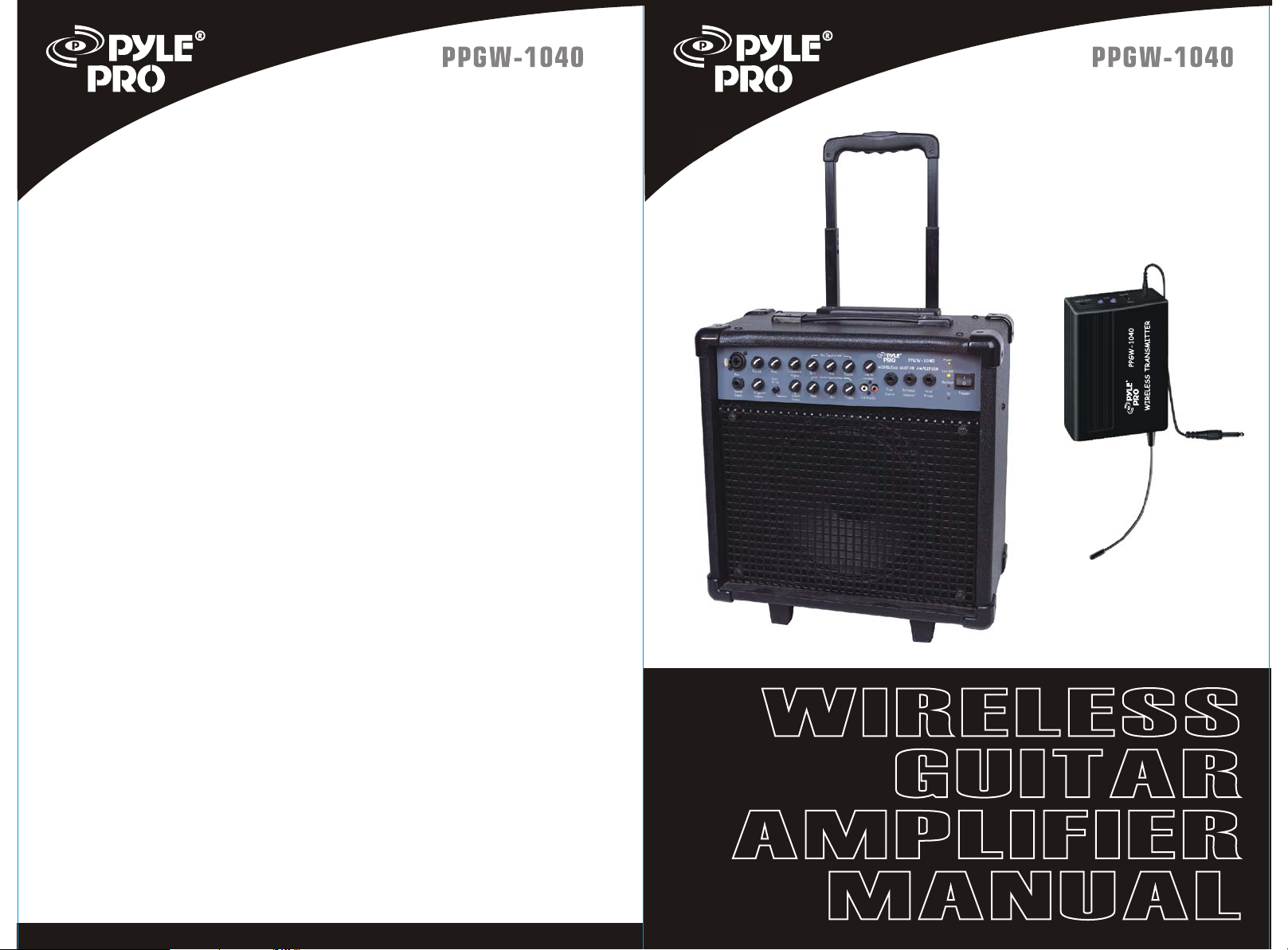
WIRELESS TRANSMITTER
Antenna: External
RF Output: <10mW
Spurious: <-60dB
Battery: one 9V battery
CONTENTS
1.Introduction Pg1
2.Safety instruction Pg2
3.Parts description Pg3~Pg5
4.Troubleshooting Pg6
5.Specifications Pg7~Pg8
INTRODUCTION
Thank you for purchasing
are confident you will have many years of use and enjoyment from our
amp.
Our new range of amps are a culmination of years of development, work
and careful testing. Every product is designed to give you a great piece
of equipment that represents amazing value and features the highest
quality materials available today.
our PPGW 1040 wireless guitar amplifier. We
This manual will help you understand some of the great features of your
amp.
8
1
Page 3

SAFETY INFORMATION
SPECIFICATIONS
1. Read and follow instructions carefully. Store the instructions in a
safe place for future reference.
2. Do not tamper with the power cord.
3. Protect the unit from contact with liquids. Do not place objects filled
with liquid on the unit. Do not spray the unit with liquid cleaners.
Clean with a slightly dampened cloth, wiping the surfaces.
4. If the amplifier has sustained damage, discontinue use. Refer
immediately to qualified personnel.
5. Protect the unit from temperature extremes of excessive heat, rain
and moisture.
6. This amplifier is capable of achieving high volume levels, as such
there is potential for hearing damage if improperly used.
WARNING: TO REDUCE THE RISK OF ELECTRIC SHOCK DO
NOT OPEN THE UNIT. DO NOT DEFEAT THE GROUND PIN OF
THE POWER CORD.
CAUTION: TO REDUCE THE RISK OF ELECTRIC SHOCK DO
NOT EXPOSE THE UNIT TO RAIN OR MOISTURE.
CAUTION: THERE ARE NO USER SERVICEABLE PARTS INSIDE.
PLEASE REFER SERVICING TO QUALIFIED SERVICE PERSONNEL.
OPENING UNIT WlLL VOID WARRANTY
AMPLIFIER
1/4'' Guitar Input for Wired Connection
1/4''/XLR Combo Mic Input
Stereo RCA CD/Line Input with Volume Control
External Speaker and Headphone Outputs
Bass, Mid, Treble & Volume Controls on Guitar
Echo, Bass, Mid, Treble & Volume Controls on Mic
Overdrive with Footswitch Control
RF, Charge, Low Batt & Power LED Indicators
Operation range: 300 ft.
Unit Battery Life: Approx. 3 Hours
Transmitter Battery Life: Approx. 6 Hours
10'' Full Range Speaker
400W Peak Power
Telescoping Handle & Caster Wheels
110/220 Voltage Switchable
Dimensions: 15.7''L x 8.9''W x 15.2''H
Weight: 34 lbs.
BUILT-IN RECEIVER
Oscillation mode: Quartz controlled
Carrier Frequency Range: 710.4MHz
Stability: 0.005%
Max Deviation: 56KHz with level limiting
Dynamic Range: >110dB
S/N Ratio: >100dB
T.H.D: <0.5%
Frequency Response: 60Hz~18KHz
Operating range:
Sensitivity: 6dB V at S/N>80dB
Image Rejection: >60dB
Stability: >80dB
300 Feet
2
7
Page 4

TROUBLESHOOTING
PARTS DESCRIPTION
TROUBLESHOOTING
If you are having trouble with your amplifier, these instructions below may
help you before you call a service technician.
1. Check that the power cord is plugged into a power outlet.
2. Check that the power is turned on at the outlet. If you are at a gig, make
sure the stage power has been turned on.
3. Check that the control knobs have been sufficiently turned up.
4. Check that the instrument is correctly plugged into the amplifier, both at
the instrument and at the amplifier input.
5. Check the instrument lead -faulty leads are one of the most common
causes of problems.
6. Check that the volume is turned up on the instrument.
If your amplifier still does not function, contact your local dealer or an
authorized service agent.
WIRELESS TRANSMITTER
AUDIO OUTPUT JACK
AUDIO SWITCH
ON MUTE
MIC/LINE
AUDIO POWER ATTENUATION POWER
LOW BATTERY LED
VOLUME SWITCH
LOW BAT
-20dB
0dB
POWER LED
BELT CLIP
POWER SWITCH
OFF ON
BATTERY COVER
9V +
ANTENNA
AUDIO CABLE
Operation
1. Open the battery cover to install a 9V battery as per correct polarities.
Move the power switch to ON position, the power indicator will be
green to show normal operation. If the LOW BAT indicator
illuminates, this indicates the voltage is not enough for operation.
Replace the 9V battery.
indicator
2. Plug the 3.5mm plug of supplied connector to screw-lock socket of
transmitter. Plug the other end 6.35mm plug to your guitar output jack.
3. ATTENUATION is for volume adjustment. Move it to 0dB position to
get normal volume output, or to -20dB position to reduce distortion
and avoid humming.
4. If the system will not be used for a long time, please switch off the
transmitter to avoid power consumption.
6
3
Page 5

PARTS DESCRIPTION
PARTS DESCRIPTION
AMPLIFIER
Front Panel
1 2 3 4 5 6 7 8
Mic Equalization
WIRELESS GUITAR AMPLIFIER
Line In
Volume
Foot
Switch
Cd/line In
External
Speaker
Mic
Guitar
Input
Mic.vol Echo
W/guitar
Volume
Over
Drive
Overdrive
Volume
Crunch
Factor
Bass
Bass
Mid
Guitar Equalization
Mid
Treble
Treble
9 10 11 12 13 14 15 16 17 18 19
Rear Panel
25 26 27
AC INPUT
110V/220V SWITCH
PPGW-1040
Head
Phone
22 23 24
20 21
Power
Low Batt
Recharge
Rf
ANT
Power
1. Wired MIC input jack: suitable for either unbalanced 6.35mm plug or
XLR plug.
2. MIC volume control
3. MIC echo control
4. Over Drive volume: effective only when guitar over drive is in use.
5. MIC BASS control
6. MIC MID control
7. MIC TREBLE control
8. Line input volume control
9. Wired guitar input jack
10. Wired or wireless guitar volume control
11. Wired or wireless guitar over drive: push button to engage
12. Wired or wireless guitar crunch factor control
13. Wired or wireless guitar BASS control
14. Wired or wireless guitar MID control
15. Wired or wireless guitar TREBLE control
16. RCA CD/Line input jack
17. Foot switch
18. External speaker output jack
19. Headphone output jack
20. Power LED
21. Low battery LED
22. Recharge LED
23. RF indicator
24. Main Power switch
25. AC input jack
26. AC 110V/220V switch
27. Antenna
54
 Loading...