

Page 1
Installation Manual
Installation and service of this appliance should be performed by
qualified personnel. Hearth & Home Technologies recommends
HHT Factory Trained or NFI certified professionals.
Installation & Appliance Set-Up
INSTALLER: Leave this manual with party responsible for use and operation.
OWNER: Retain this manual for future reference.
NOTICE: DO NOT DISCARD THIS MANUAL
WARNING
If the information in these instruc-
MT. VERNON E2 INSERT
PELLET APPLIANCE
Model(s):
MTVI-E2-MBK-C MTVI-E2-CSB-C
MTVI-E2-PMH-C
• Do not store or use gasoline or other ammable vapors and liquids in the vicinity of
this or any other appliance.
• Do not over re - If appliance or chimney
connector glows, you are over ring. Over
ring will void your warranty.
tions is not followed exactly, a
re could result causing property
damage, personal injury, or death.
CAUTION
Tested and approved for wood pellets only. Burning of
any other type of fuel voids your warranty.
NOTE
To obtain a French translation of this manual, please contact
your dealer or visit www.quadrare.com
00Pour obtenir une traduction française de ce manuel, s’il vous
plaît contacter votre revendeur ou visitez www.quadrare.com
• Comply with all minimum clearances to
combustibles as specied. Failure to
comply may cause house re.
WARNING
HOT SURFACES!
Glass and other surfaces are hot
during operation AND cool down.
Hot glass will cause burns.
• Do not touch glass until it is cooled
• NEVER allow children to touch glass
• Keep children away
• CAREFULLY SUPERVISE children in same room as
replace.
• Alert children and adults to hazards of high temperatures
• High temperatures may ignite clothing or other
ammable materials.
• Keep clothing, furniture, draperies and other ammable
materials away.
1 7082-150C January 4, 2018
CAUTION
Check building codes prior to installation.
• Installation MUST comply with local, regional, state and national codes and regulations.
• Consult local building, re ofcials or authorities having jurisdiction about restrictions, installation inspection, and permits.
Page 2

MT VERNON E2 INSERT-C
Safety Alert Key:
• DANGER! Indicates a hazardous situation which, if not avoided will result in death or serious injury.
• WARNING! Indicates a hazardous situation which, if not avoided could result in death or serious injury.
• CAUTION! Indicates a hazardous situation which, if not avoided, could result in minor or moderate injury.
• NOTICE: Indicates practices which may cause damage to the appliance or to property.
TABLE OF CONTENTS
1 Important Safety Information .............3
A. Appliance Certication ......................................................3
B. BTU & Efciency Specications........................................3
C. Glass Specications .........................................................3
D. Electrical Rating................................................................3
E. Mobile Home Approved .................................................... 3
F. Non-Combustible Materials ................................................3
G. Combustible Materials .......................................................3
2 Getting Started ....................................4
A. Design, Installation & Location Considerations ..........................4
B. Tools And Supplies Needed ..............................................5
C. Inspect Appliance and Components .................................5
D. Install Checklist..................................................................6
3 Dimensions and Clearances ..............7
A. Appliance Dimensions ......................................................7
B. Clearance To Combustibles, US & Canada .......................8
C. Minimum Opening for Masonry &
Zero Clearance Fireplaces ................................................9
D. Hearth Extension ...............................................................9
E. Floor Protection .................................................................9
F. Installation into a Factory-Built Fireplace ..........................10
G. Installation into a Masonry Fireplace .................................11
H. Prefabricated Metal Chimney ...........................................11
4 Vent Information ................................12
A. Venting Termination Minimum Requirements ...................12
B. Avoiding Smoke and Odors ...............................................13
C. Negative Pressure ............................................................14
D. Draft 14
E. Chimney and Exhaust Connection ..................................14
F. Equivalent Feet of Pipe ....................................................15
G. Pipe Selection Chart ........................................................15
5 Venting Systems ...............................16
A. Full Reline With Outside Air - Horizontal ..........................16
B. Full Reline With Outside Air - Vertical ..............................17
6 Appliance Set-Up ..............................18
A. Leveling System ...............................................................18
B. Outside Air Kit Instructions ................................................18
C. Hearth Support .................................................................18
D. Removal of Cast Sides ....................................................19
E. Surround and Trim Set - Cast ...........................................19
F. Surround & Trim Set, Basic ...............................................20
G. Optional Log Set Placement Instructions ..........................20
H. Programmable Wall Thermostat Installation ......................21
I. Power Cord .........................................................................23
J. Trim Adjustment..................................................................23
7 Mobile Home Installation ..................24
8 Reference Materials ..........................25
A. Service and Maintenance Log ...........................................25
B. Accessory List ....................................................................27
Quadra-Fire is a registered trademark of Hearth & Home Technologies.
2 7082-150C January 4, 2018
Page 3
1 Important Safety Information
MT VERNON E2 INSERT-C
A. Appliance Certication
Model Mt. Vernon Insert Pellet Appliance E2
Laboratory OMNI Test Laboratories, Inc.
Report No. 061-S-84-2
Type Solid Fuel Room Appliance, Pellet Fuel Burn-
ing Type
Standard ASTM E1509-12, ULC-S628-93 and (UM)
84-HUD, Mobile Home Approved.
FCC Complies with Part 15 of FCC Rules. Opera-
tion is subject to the following two conditions:
(1) this device may not cause harmful interference, and (2) this device must accept any
interference received, including interference
that may cause undesired operation.
NOTICE: This installation must conform with local codes. In the
absence of local codes you must comply with the ASTM E150912, ULC S628-93, (UM) 84-HUD and ULC/ORD-C-1482.
The Quadra-Fire Mt. Vernon E2 Pellet Insert Appliance meets
the U.S. ENVIRONMENTAL PROTECTION AGENCY Certied to
comply with 2020 particulate emission standards at 0.74 G/HR EPA
CFR subpart AAA, using ASTM E2779-10, ASTM 2515-11 MethodPellet Appliance sections, CSA B415.1-10. This pellet appliance
needs periodic inspection and repair for proper operation. It
is against federal regulations to operate this pellet appliance
in a manner inconsistent with the operating instructions in
the owner’s manual.
B. BTU & Efciency Specications
Emissions Report Number: 0061PS094E
EPA Certication #: 98-17
EPA Certied Emissions: 0.74 g/hr
*LHV Tested Efciency: 83.2%
**HHV Tested Efciency: 77.9%
***EPA BTU Output: 12,682 - 39,428 / HR
****BTU Input: 16,396 - 50,775 / HR
Vent Size: 3 or 4, “L” or “PL”
Hopper Capacity: 52 lbs.
Fuel Wood Pellets
* Weighted average LHV efciency using data collected during
EPA emissions test.
**Weighted average HHV efciency using data collected during
EPA emissions test.
***A range of BTU outputs based on HHV and the burn rates from
the low and high EPA tests.
****Based on the maximum feed rate per hour multiplied by
approximately 8600 BTU’s which is the average BTU’s from a
pound of pellets.
C. Glass Specications
This appliance is equipped with 5mm ceramic glass.
Replace glass only with 5mm ceramic glass. Please contact your dealer for replacement glass.
D. Electrical Rating
115 VAC, 60 Hz, Start 2.9 Amps, Run 2.45 Amps
E. Mobile Home Approved
• This appliance is approved for mobile home installations when
not installed in a sleeping room and when an outside combustion
air inlet is provided.
• The structural integrity of the mobile home oor, ceiling, and
walls must be maintained.
• The appliance must be properly grounded to the frame of the
mobile home and use only Listed pellet vent Class “L” or “PL” con-
nector pipe.
• Outside Air Kit (OAK-3) must be installed in a mobile home
installation.
F. Non-Combustible Materials
Material which will not ignite and burn, composed of any combination of the following:
- Steel - Plaster
- Brick - Iron
- Concrete - Tile
- Glass - Slate
Materials reported as passing ASTM E 136, Standard Test
Method for Behavior of Metals, in a Vertical Tube Furnace of
750° C.
G. Combustible Materials
Material made of/or surfaced with any of the following materials:
- Wood - Compressed Paper
- Plant Fibers - Plastic
- Plywood/OSB - Sheet Rock (drywall)
Any material that can ignite and burn: ame proofed or not, plas-
tered or non-plastered.
WARNING
Fire Risk.
Hearth & Home Technologies disclaims any
responsibility for, and the warranty will be
voided by, the following actions:
• Installation and use of any damaged appliance.
• Modication of the appliance.
• Installation other than as instructed by Hearth & Home
Technologies.
• Installation and/or use of any component part not approved by
Hearth & Home Technologies.
• Operating appliance without fully assembling all components.
• Operating appliance without legs attached (if supplied with
appliance).
• Do NOT Over re - If appliance or chimney connector glows,
you are over ring.
Any such action that may cause a re hazard.
Improper installation, adjustment, alteration, service or maintenance
can cause injury or property damage.
For assistance or additional information, consult a qualied installer,
service agency or your dealer.
NOTE: Hearth & Home Technologies, manufacturer of this appliance, reserves the right to alter its products, their specications
and/or price without notice.
January 4, 2018 7082-150C 3
Page 4
MT VERNON E2 INSERT-C
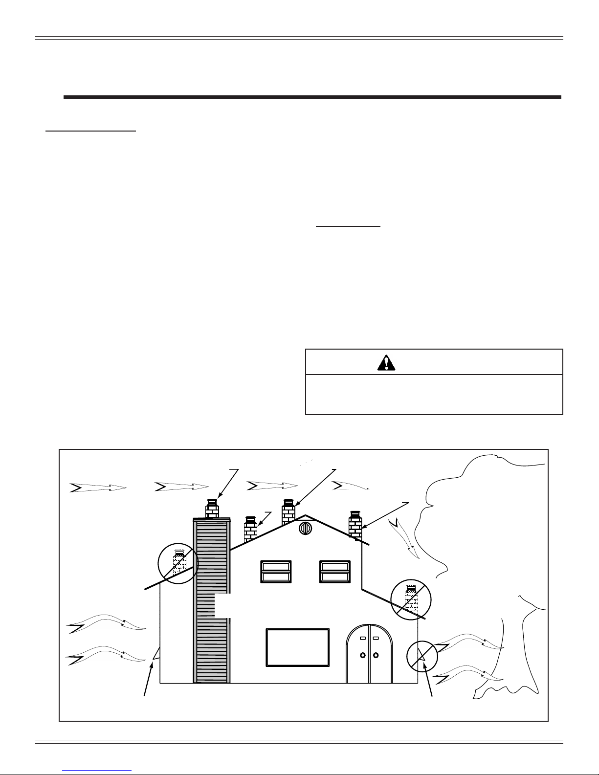
Marginal Location:
• Below peak
Location NOT recommended:
• Not the highest point of the roof
• Wind loading possible
Multi-level Roofs
Windward
Leeward
Recommended:
Outside Air Intake
on windward side
NOT recommended:
Outside Air Intake
on leeward side
Recommended Location:
• Above peak
Recommended:
• Insulated exterior chase
in cooler climates
Recommended Location:
• Above peak
• Inside heated space
Location NOT recommended:
• Too close to tree
• Below adjacent structure
• Lower roof line
• Avoid outside wall
Marginal Location:
• Wind loading possible
2 Getting Started
Install Guide
A. Design, Installation & Location Considerations
1. Appliance Location
NOTICE: Check building codes prior to installation.
• Installation MUST comply with local, regional, state and
national codes and regulations.
• Consult insurance carrier, local building inspector, re
ofcials or authorities having jurisdiction over restrictions,
installation inspection and permits.
It is a good idea to plan your installation on paper, using exact
measurements for clearances and oor protection, before
actually beginning the installation. Location of the appliance
and chimney will affect performance.
Consideration must be given to:
• Safety, convenience, trafc ow
• Placement of the chimney and chimney connector and to
minimize the use of chimney offsets.
Since pellet exhaust can contain ash, soot or sparks, you
must consider the location of:
• Windows
• Air Intakes
• Air Conditioner
• Overhang, softs, porch roofs, adjacent walls
• Landscaping, vegetation
• Horizontal or vertical vent termination
2. Floor Support
The supporting oor under the appliance must be able to
handle the weight of the appliance, fuel load and the weight
of the chimney.
Ensure that your oor will support these weights prior to
installation. Add sufcient additional support to meet this
weight requirement prior to installation. The weight of the
appliance is 510 lbs. with a full load of fuel the max weight
is 557 lbs.
• Place the appliance where there will be a clear passage
for a Listed chimney through the ceiling and roof (vertical)
or through exterior wall (horizontal).
• Installing the required outside air kit will affect the location
of the vent termination.
When locating vent and venting termination, the ideal location is to vent above roof line when possible. This minimizes
the affects of wind loading.
WARNING
Risk of Fire! Damaged parts could impair safe operation.
Do NOT install damaged, incomplete or substitute components.
Figure 4.1
4 7082-150C January 4, 2018
Page 5
MT VERNON E2 INSERT-C
B. Tools And Supplies Needed
Tools and building supplies normally required
for installation, unless installing into an existing
masonry replace:
Reciprocating Saw Channel Locks
Hammer Phillips Screwdriver
Tape Measure Plumb Line
1/4” Self-Tapping Screws Framing Material
Hi-temp Caulking Material Gloves
Safety Glasses Framing Square
Electric Drill & Bits (1/4”) Level
May also need:
Vent Support Straps Venting Paint
C. Inspect Appliance and Components
• Open the appliance and remove all the parts and articles
packed inside the Component Pack. Inspect all the parts
and glass for shipping damage.
• Report to your dealer any parts damaged in shipment.
•
All labels have been removed from the glass door.
•
Plated surfaces have been wiped clean with a soft cloth,
if applicable.
• Read all the instructions before starting the installation.
Follow these instructions carefully during the
installation to ensure maximum safety and benet.
• Follow pipe manufacturer instructions for installation
and air clearance requirements.
WARNING
Risk of Fire!
Damaged parts could impair safe operation.
Do NOT install damaged, incomplete or
substitute components.
WARNING
Hearth & Home Technologies disclaims any
responsibility for, and the warranty will be
voided by, the following actions:
• Installation and use of any damaged
appliance.
• Modication of the appliance.
• Installation other than as instructed by Hearth & Home
Technologies.
• Installation and/or use of any component part not approved by
Hearth & Home Technologies.
• Operating appliance without fully assembling all components.
• Do NOT Over re
Or any such action that may cause a re hazard.
NOTE: Upon removing the appliance from the replace
a tag shall be permanently attached to the replace
indicating it has been altered and should be inspected
by a qualied person prior to re-use as a convectional
replace (tag included in component pack).
January 4, 2018 7082-150C 5
Page 6
MT VERNON E2 INSERT-C
!
D. Install Checklist
This standard work checklist is to be used by the installer in conjunction with, not instead of, the instructions contained in this installation manual.
ATTENTION INSTALLER:
Follow this Standard Work Checklist
Customer:
Date Installed:
Lot/Address:
Location of Appliance:
Installer:
Dealer/Distributor Phone Number:
Serial Number:
Model Name:
WARNING! Risk of Fire or Explosion! Failure to install appliance to these instructions can lead to a fire or
explosion.
Appliance Install
Verified clearance to combustibles.
Appliance is leveled and connector is secured to appliance.
Hearth extension size/height decided.
Outside air kit installed.
Floor protection requirements have been met.
If appliance is connected to a masonry chimney, it should be cleaned and
inspected by a professional. If installed to a factory built metal chimney, the
chimney must be installed according to the manufacturer’s instructions and
clearances.
Venting/Chimney
Chimney configuration complies with diagrams.
Chimney installed, locked and secured in place with proper clearance.
Chimney meets recommended height requirements (5 feet minimum vertical).
Roof flashing installed and sealed.
Terminations installed and sealed.
__________________________________________________________________________
______________________________________________________________________
_______________________________________________________________________
________________________________________________________________
___________________________________________________________________________
________________________________________________________
______________________________________________________________________
_______________________________________________________________________
YES IF NO, WHY?
Electrical
120 VAC unswitched power provided to the appliance.
Check outlet with multi-meter for proper polarity and voltage (115-120 VAC).
Record voltage reading: _____________
Clearances
Verified all clearances meet installation manual requirements.
Mantels and wall projections comply with installation manual requirements.
Floor protection and heart extensions installed per manual requirements.
Appliance Setup
All protective materials removed.
All labels have been removed from the door.
All packaging materials are removed from inside/under appliance.
Manual bag and all of its contents are removed from inside/under the appliance
and given to the party responsible for use and operation.
Started appliance and verified that all motors and blowers operate as they should.
Checked draft using a Manometer. Record readings: ______________________
Checked vacuum using a Manometer. Record readings: ____________________
Hearth & Home Technologies recommends the following:
Photographing the installation and copying this checklist for your file.
That this checklist remain visible at all times on the appliance until the installation is complete.
Comments: Further description of the issues, who is responsible (Installer/Builder/Other Trades, ets.) and corrective action needed:
Comments communicated to party responsible
__________________________ by ______________________ on ____________
(Builder/Gen. Contractor) (Installer) (Date)
6 7082-150C January 4, 2018
Page 7
29-3/4 in
[756mm]
23-7/8 in
[605mm]
26-7/8 in [683mm]
11-7/8 in
[302mm]
24-1/8 in
[613mm]
34-1/2 in
[876mm]
45 in [1143mm]
11-3/4 in
[297mm]
18-1/2 in [469mm]
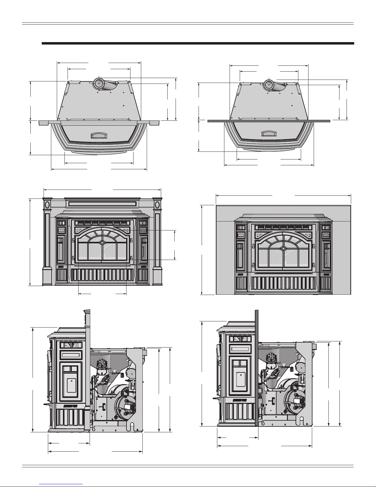
3 Dimensions and Clearances
A. Appliance Dimensions
32 in [814mm]
23-7/8 in [606mm]
MT VERNON E2 INSERT-C
32 in [814mm]
23-7/8 in [606mm]
15 in
[382mm]
13-1/8 in
[333 mm]
26-1/4 in [667mm]
36-5/8 in [93 mm]
Figure 7.1 - Top View with Cast Panel Set
14-1/8 in
[359mm]
16-1/4 in
[413mm]
15-1/8 in
[384mm]
13 in
[330mm]
26-1/4 in [667mm]
36-5/8 in [930mm]
14-1/4 in
[361mm]
Figure 7.4 - Top View with Basic Surround Panel Set
50 in [1270mm]
33 in
[838mm]
16-3/8 in
[415mm]
Figure 7.2 - Front View with Cast Panel Set
Figure 7.3 - Side View with Cast Panel Set
January 4, 2018 7082-150C 7
Figure 7.5 - Front View with Basic Surround Panel Set
29-3/4 in
[756mm]
11-13/16 in
[300mm]
24-1/8 in
[613mm]
23-7/8 in
[605mm]
26-7/8 in [683mm]
Figure 7.6 - Side View with Basic Surround Set
Page 8
MT VERNON E2 INSERT-C
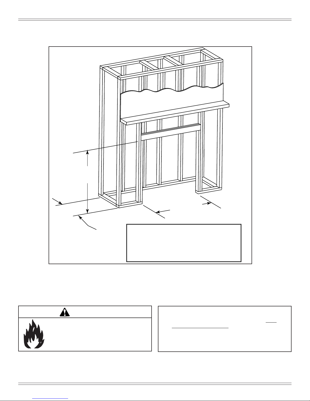
B. Clearance To Combustibles, US & Canada
Built-in Appliance - Rear Vent
Figure 8.1
26-7/8 in.**
(683 mm)
19-3/8 in.*
(572 mm)
*If interior of chase will be drywalled, add the
**From finished floor protection. The size of
your floor protector choice must be added to
WARNING
Fire Risk.
Comply with all minimum clearances to combustibles as specied.
Failure to comply may cause house re.
36 in.
(914 mm)
thickness to this measurement.
this dimension.
NOTE:
• Illustrations reect typical installations and are FOR
DESIGN PURPOSES ONLY.
• Illustrations/diagrams are not drawn to scale.
• Actual installation may vary due to individual design
preference.
8 7082-150C January 4, 2018
Page 9
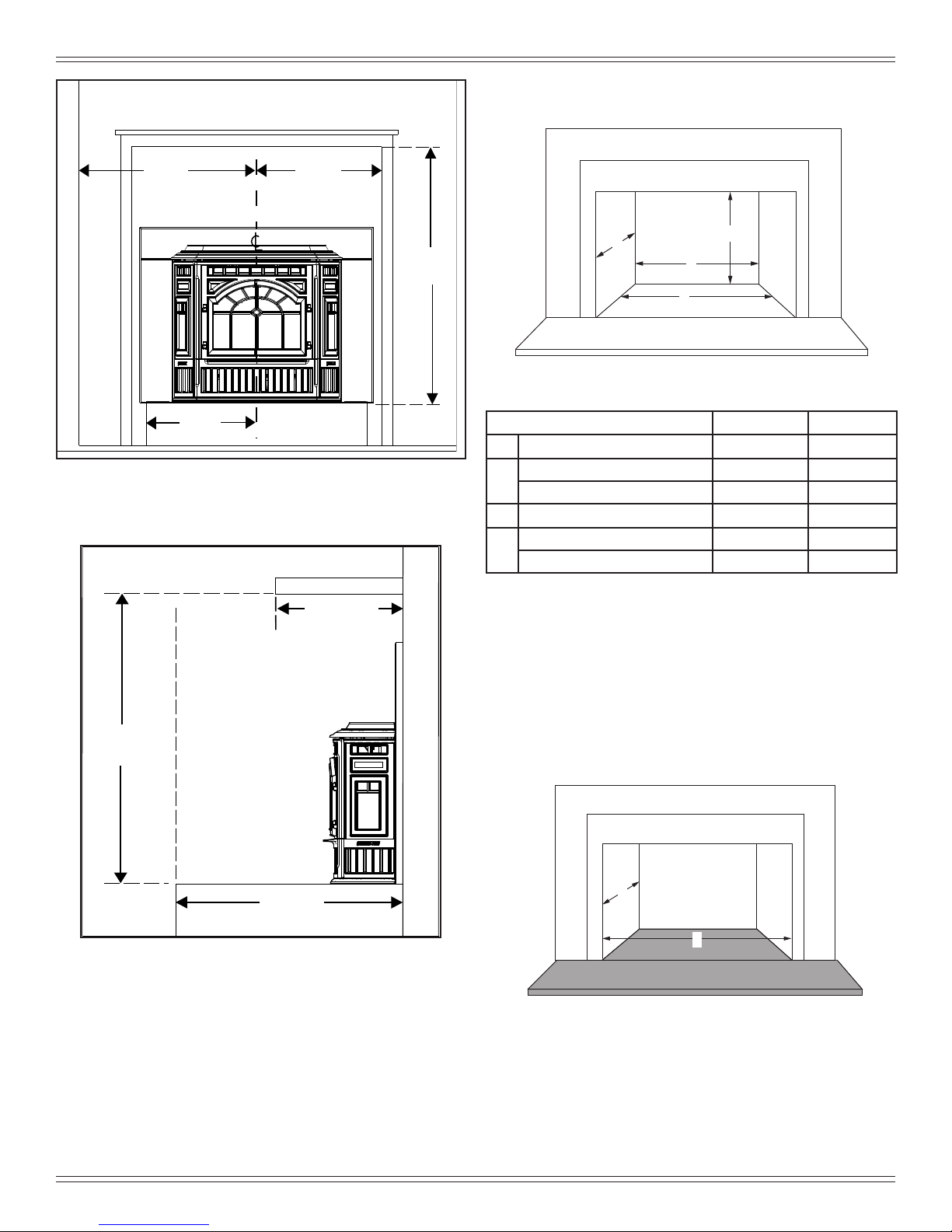
FIREPLACE FRONT SURFACE
USA 15-1/8
CANADA 15-1/8 (537mm)
41-3/4
1060mm
12in max *
MANTEL
Figure 9.1
SIDE TRIM
SIDE WALL
TOP TRIM
18-5/16 in
(465mm)
24-5/16 in
(618mm)
HEARTH
EXTENSION
16
(406mm)
29-3/4 in
(1010mm)
C
D
A
B
Note: If trim measurement is over 3/4 in (19mm) in
depth use mantle or side clearances to combustibles.
MT VERNON E2 INSERT-C
C. Minimum Opening for Masonry & Zero
Clearance Fireplaces
Figure 9.3
Minimum Opening Dimensions Inches Millimeters
A Height
Front Width (Steel Panel Set) 32-1/4 819
B
Front Width (Cast Panel Set) 32-1/4 819
C Back Width
Depth (Steel Panel Set) 16-5/8 422
D
Depth (Cast Panel Set) 16-1/4 413
24-3/8 619
24-1/8 613
Figure 9.2
*If mantel depth is 10 inches or less, than the height from the
hearth to the bottom of the mantel is 39-3/4 inches.
Note: Minimum opening dimensions include a
1/4” (6mm) clearance around unit.
D. Hearth Extension
Use a non-combustible ember oor protector, extending
beneath the appliance and to the front, and to the sides as
indicated in sub-section E. Floor Protection.
E. Floor Protection
D
B
Figure 9.4
January 4, 2018 7082-150C 9
Page 10

MT VERNON E2 INSERT-C
Mark area of
floor to cut
Starter hole
Keep sharp edge of
metal floor away from
power cord
WARNING
F. Installation into a Factory-Built Fireplace
The following modications are permissible:
• Removal of damper or locked in open position
• Removal of smoke shelf or bafe
• Removal of ember catches
• Removal of re grate
• Removal of view screen/curtain
• Removal of doors
• Removal of factory-built replace oor
• External trim pieces which do not affect the operation of
the replace may be removed providing they can be stored
on or within the replace for reassembly if the insert is
removed.
• The permanent metal warning label provided must be
attached to the back of the replace, with screws or
nails, stating that the replace may have been altered to
accommodate the insert, and must be returned to original
condition for use as a conventional replace. Figure 10.1
THIS FIREPLACE MAY HAVE BEEN ALTERED
TO ACCOMMODATE AN INSERT. IT MUST BE
RETURNED TO ITS ORIGINAL CONDITION
BEFORE USE AS A SOLID FUEL BURNING
FIREPLACE.
250-2061
250-2061
The following is only one example as there are many differ-
ent models of factory-built replaces.
NOTE: This example is for reference only. Any modica-
tions must not compromise the structural integrity
or reduce the protection for combustible materials.
Figure 10.2. Measure and mark the metal
oor for cutting. With a drill, make a starter
hole in each corner.
Figure 10.1
• If the hearth extension is lower than the replace opening,
the portion of the insert extending onto the hearth must be
supported.
• Manufacturer designed adjustable support kit can be
ordered from your dealer.
NOTE: Refer to chimney liner manufacturer for recom-
mendations on supporting the liner. Installation
into replaces without a permit will void the listing.•
• The rebrick (refractory), glass doors, screen rails,
screen mesh and log grates can be removed from a factory-built rebox in order to gain minimum insert opening requirements.
• Any smoke shelves, shields and bafes may be removed
from a factory-built rebox if attached with mechanical
fasteners.
• The metal oor of the factory-built rebox may be
removed to facilitate the installation of the insert only
when a 1 inch (25mm) airspace is provided between the
insert and the oor of outer wrap.
Figure 10.3. Using a saws-all, cut out the
oor.
Figure 11.1. Place the insert into the facto-
ry-built rebox. Ensure that the power cord
can not be damaged by the sharp metal
edge. You may need to cut out a notch to
accommodate the cord.
10 7082-150C January 4, 2018
Page 11

G. Installation into a Masonry Fireplace
All modications that can be made to a Factory Built Fireplace can be made to a Masonry Fireplace.
In addition DO NOT remove any brick or mortar from the
existing replace.
MT VERNON E2 INSERT-C
WARNING
Risk of Fire!
Follow venting manufacturer’s clearances and
instructions when installing venting system.
WARNING
• Removing oor of replace must not weaken structure
of rebox or reduce protection for combustible materials.
• Final approval of this installation type is contingent upon
the appropriate local authority having jurisdiction.
H. Prefabricated Metal Chimney
The chimney can be new or existing, masonry or prefabricated
and must meet the following minimum requirements:
• Must be minimum 6 inch (152mm) inside diameter of
high temperature chimney listed to UL 103 HT (2100oF)
or ULC-S628.
• Must use components required by the manufacturer for
installation.
• Must maintain clearances required by the manufacturer
for installation.
• Refer to manufacturers instructions for installation
•This insert is listed to ASTM E 1509-12 Standard and
is approved for installation into listed factory-built zero
clearance replaces listed to UL 127 conforming to the
following specications and instructions:
•The original factory-built clearance replace chimney
cap must be re-installed after installing the approved
chimney liner meeting type UL 103 HT requirements
(2100°F) per UL 1777.
•If the chimney is not listed as meeting HT requirements,
or if the factory built replace was tested prior to 1998, a
full height listed chimney liner must be installed from the
appliance ue collar to the chimney top.
•The liner must be securely attached to the insert ue collar
and the chimney top.
•The air ow of the factory-built zero-clearance replace
system must not be altered. The ue liner top support
attachment must not reduce the air ow for the existing
air-cooled chimney system.
•No dilution air is allowed to enter the chimney.
1. Secure the replace damper in the open position. If
this cannot be accomplished, it will be necessary to
remove the damper
2. Seal damper area of chimney around chimney
connector with a high temperature sealant or seal
insert against the face of the replace.
3. Both methods must be removable and replaceable
for cleaning and re-installation.
NOTICE: In Canada when using a factory-built chimney it must be safety listed, Type UL103 HT (2100oF)
[1149oC] CLASS “A” or conforming to CAN/ULCS629M, STANDARD FOR 650oC FACTORY-BUILT
CHIMNEYS.
January 4, 2018 7082-150C 11
Page 12

MT VERNON E2 INSERT-C
V
4 Vent Information
A. Venting Termination Minimum Requirements
D
O
E
V
Inside Corner
G
V
A
V
N
Electrical
Service
N
V
N
N
V
H
P
L
V
B
C
FIXED
V
CLOSED
F
V
B
V
Termination Cap
OPEN
OPEN
V
V
B
X
Air Supply Inlet
FIXED
CLOSED
B
A
G
G
Gas Meter
M
I
V
Restricted Area
X
J or K
Figure 12.1
All minimum clearances are listed with an Outside Air Kit (OAK) installed, unless otherwise noted in table below.
A 12 in. Above Finish Grade (the grade surface
must be a non-combustible material
B 12 in.
Open door or window: below or to the side
48 in. no OAK
B 12 in. Open door or window: above
C 6 in. Permanently closed window: above, below
or to the side
D 18 in.
36 in. no OAK
Vertical clearance to a ventilated soft
located above the terminal within a hori-
zontal distance of 2 ft from the center-line
of the terminal
E 12 in. Clearance to unventilated soft
F 12 in. Clearance to outside corner
G 12 in. Clearance to inside corner
H 36 in. Above gas meter/regulator measured from
horizontal center-line of regulator
I 36 in. USA
Clearance to service regulator vent outlet
72 in. Canada
J 12 in.
48 in. no OAK
Clearance to non-mechanical air supply
inlet to the building or the combustions air
inlet to any other appliance
K 10 ft horizontal
Clearance to mechanical air supply
3 ft vertical
L 7 ft. Above paved sidewalk, paved driveway
located on public property
M 12 in. Under an open veranda, porch, deck or
balcony
N See Note
below*
Electric service: above, below or to the
side (location must not obstruct or interfere
with access)
O 24 in. Adjacent building, fences and protruding
parts of the structure
P 12 in. Clearance above roof line for vertical
terminations
24 in. Above grass, top of plants, wood or any other com-
bustible
12 in.
36 in. no OAK
Clearance from any forced air intake of other appliance
12 in. Clearance horizontally from combustible wall
15 in. Vented directly through a wall, minimum length of
horizontal pipe
6 in. horizontal
12 in. vertical
Minimum horizontal or vertical terminations must
protrude from wall
NOTICE:
Do NOT Terminate Vent:
• In any location that will allow ue gases or soot from en-
tering or staining the building
• In any location which could create a nuisance or hazard
• In any enclosed or semi-enclosed area such as a carport,
garage, attic, crawl space, under a sun deck or porch,
narrow walkway
• Closely fenced area, or any location that can build up
a concentration of fumes such as a stairwell, covered
breezeway, etc.
NOTICE:
Termination must exhaust above air inlet elevation.
*NOTE: Consult local building, re ofcials or authorities having jurisdic-
tion. Local codes or regulations may require different clearances.
12 7082-150C January 4, 2018
Page 13

MT VERNON E2 INSERT-C
B. Avoiding Smoke and Odors
Negative Pressure, Shut-Down and Electrical Power
Failure
To reduce the probability of back-drafting or burn-back in
the pellet appliance during power failure or shut down con-
ditions, it must be able to draft naturally without exhaust
blower operation.
Negative pressure in the house will resist this natural draft if
not accounted for in the pellet appliance installation.
Heat rises in the house and leaks out at upper levels. This
air must be replaced with cold air from outdoors which ows
into lower levels of the house.
Vents and chimneys into basements and lower levels of the
house can become the conduit for air supply and reverse
under these conditions.
Outside Air
An outside air kit is recommended in all installations and
must be ordered separately.
Per national building codes, consideration must be given to
combustion air supply to all combustion appliances. Failure
to supply adequate combustion air for all appliance demands
may lead to back drafting of those and other appliances.
When the appliance is roof vented (strongly recommended):
The air intake is best located on the exterior wall oriented
towards the prevailing wind direction during the heating
season.
When the appliance is side-wall vented:
The air intake is best located on the same exterior wall as
the exhaust vent outlet and located lower on the wall than
the exhaust vent outlet.
Vent Congurations
When installing a pellet appliance with a horizontal vent conguration the frequency of power outages should be considered:
• Power outages during operation will cause the appliance
to immediately turn off and may create conditions where
smoke will back draft into the house. In order to reduce
the likelihood of smoke back drafting into the house
during a power outage, Hearth and Home Technologies
strongly suggests:
• Installing the pellet venting with a minimum vertical
run of 5 feet (1.52m).
• Installing the outside air kit at least 4 feet (1.22m)
below the vent termination.
•
To prevent soot damage to exterior walls of the house and to
prevent re-entry of soot or ash into the house:
• Maintain specied clearances to windows, doors and
air inlets, including air conditioners.
• Vents should not be placed below ventilated softs.
Run the vent above the roof.
• Avoid venting into alcove locations.
• Vents should not terminate under overhangs, decks or
onto covered porches.
• Maintain minimum clearance of 12 inches (305mm)
from the vent termination to the exterior wall. If you
see deposits developing on the wall, you may need to
extend this distance to accommodate your installation
conditions.
The outside air supply kit can supply most of the demands of
the pellet appliance, but consideration must be given to the
total house demand.
House demand may consume the air needed for the appli-
ance. It may be necessary to add additional ventilation to
the space in which the pellet appliance is located.
Consult with your local HVAC professional to determine the
ventilation demands for your house.
CAUTION
• DO NOT CONNECT THIS Appliance TO A CHIMNEY
FLUE SERVICING ANOTHER APPLIANCE.
• DO NOT CONNECT TO ANY AIR DISTRIBUTION DUCT
OR SYSTEM.
January 4, 2018 7082-150C 13
Page 14

MT VERNON E2 INSERT-C
C. Negative Pressure
WARNING
Risk of Asphyxiation!
Negative pressure can cause spillage of combustion
fumes and soot.
Negative pressure results from the imbalance of air available for the appliance to operate properly. It can be strongest
in lower levels of the house.
Causes include:
• Exhaust fans (kitchen, bath, etc.)
• Range hoods
• Combustion air requirements for furnaces, water
appliances and other combustion appliances
• Clothes dryers
• Location of return-air vents to furnace or air conditioning
• Imbalances of the HVAC air handling system
• Upper level air leaks such as:
- Recessed lighting
- Attic hatch
- Duct leaks
To minimize the effects of negative air pressure:
• Install the outside air kit with the intake facing prevailing
winds during the heating season
• Ensure adequate outdoor air for all combustion appliances
and exhaust equipment
• Ensure furnace and air conditioning return vents are not
located in the immediate vicinity of the appliance
• Avoid installing the appliance near doors, walkways or
small isolated spaces
• Recessed lighting should be a “sealed can” design
• Attic hatches weather stripped or sealed
• Attic mounted duct work and air handler joints and seams
taped or sealed
D. Draft
Draft is the pressure difference needed to vent an appliance successfully. When an appliance is drafting suc-
cessfully, all combustion byproducts are exiting the home
through the chimney.
Install through the warm airspace enclosed by the building envelope. This helps to produce more draft, especially
during lighting and die-down of the re.
Considerations for successful draft include:
• Preventing negative pressure
• Location of appliance and chimney
NOTICE: Hearth & Home Technologies assumes no
responsibility for the improper performance of the chimney
system caused by:
• Inadequate draft due to environmental conditions
• Down drafts
• Tight sealing construction of the structure
• Mechanical exhausting devices
E. Chimney and Exhaust Connection
1. Chimney & Connector: Use 3 or 4 inch (76-102mm) diameter
type “L” or “PL” venting system. It can be vented vertically or
horizontally.
NOTE: The appliance exhaust outlet is designed to accommodate 3 inch venting. Use of 4 inch venting requires
the use of a 3-to-4 inch exhaust vent increaser in addition
to any other venting components needed, sold separate-
ly.
2. Mobile Home: Approved for all Listed pellet vent. If using the 3
to 6 inch (76-152mm) Top Vent Offset Adapter, use Listed double
wall ue connector. A Quadra-Fire Outside Air Kit (OAK-3) must
be used with manufactured home installations.
3. Residential: The 3 inch (76mm) vertical Top Vent Adapter Kit and
the 3 to 6 inch (76-152mm) Top Vent Offset Adapter are tested
to use 24 gauge single wall ue connector or Listed double wall
ue connector to Class A Listed metal chimneys, or masonry
chimneys meeting International Residential Code standards for
solid fuel appliances.
4. INSTALL VENT AT CLEARANCES SPECIFIED BY THE
VENT MANUFACTURER.
5. Vent Assembly to Insert Instructions:
These instructions are for connecting the vent pipe to the
vent assembly prior to installing the appliance in the replace.
a. Unlatch the vent assembly for the exhaust blower and
attach to the vent pipe end using high temperature
silicone and at least three screws.
b. Slide the appliance into place and line up the bent
assembly with the exhaust blower.
c. Make sure the high-temperature gasket is in place.
d. Latch the top vent assembly to the exhaust blower.
6. DO NOT INSTALL A FLUE DAMPER IN THE EXHAUST VENTING SYSTEM OF THIS Appliance.
7. DO NOT CONNECT THIS Appliance TO A CHIMNEY FLUE
SERVING ANOTHER APPLIANCE.
8. Disconnect the vent pipe from the appliance to allow removal
of the replace insert for the purpose of inspecting the replace
insert and the replace.
NOTE: All pipe must be welded seam pipe whenever possible.
Seal pipe joints with high temperature silicone (500°F [260°C]
minimum rated only).
WARNING
USE ONLY RECOMMENDED VENTING COMPONENTS;
OTHERWISE MAKESHIFT PARTS MAY RESULT IN PROPERTY DAMAGE, PERSONAL INJURY, OR DEATH.
14 7082-150C January 4, 2018
Page 15

2 ft.
3 in. or 4 in. (76mm or 102mm) Diameter Pipe
Equivalent Pipe
Length In Feet
ALTITUDE IN THOUSANDS OF FEET
0
20
30
1 2 3 4 5 6 7 8 9 10
4 in. (102mm) Diameter Pipe Only
10
Example 1
Example 2
F. Equivalent Feet of Pipe
The table below can help you calculate the equivalent feet
of pipe which is a method used to determine pellet vent size.
Figure 15.1.
Example of 3 Elbow-Rear Vent Termination Calculation
MT VERNON E2 INSERT-C
WARNING
Vent surfaces get HOT, can cause burns if
touched. Non-combustible shielding or guards
may be required.
2 ft.
3 ft.
Pellet Venting
Component
90o Elbow or Tee
45o Elbow
Horizontal Pipe
Vertical Pipe
2 ft.
Figure 15.1
G. Pipe Selection Chart
The chart will help you in determining proper venting size
according to the equivalent feet of pipe calculated previously
and the altitude above sea level of this installation.
Figure 15.2
a. Locate the calculated equivalent feet of pipe on the vertical
left side of the chart.
b. Move to the right horizontally on the chart until you reach
your altitude above sea level.
# of
Elbows
Feet of
3 X 5 15
Multiplied ByEquivalent
Pipe
X 3
7 X 1 7
2 X 0.5 1
Total Equivalent Feet 23
Feet
Components
Equivalent Feet
Note: This is a generic example and is not
intended to represent any specic fuel type.
c. If you fall below the diagonal line, 3 or 4 inch (76 to 102mm)
pipe may be used.
d. If it is anywhere above the diagonal line, a 4 inch (102mm)
diameter pipe is required.
NOTICE:
• A 90° elbow is 5 times as restrictive to the ow of exhaust
gases under positive pressure as 1 foot (305mm) of hori-
zontal pipe.
• A foot of horizontal pipe is twice as restrictive as a foot of
vertical pipe.
WARNING
Risk of Fire!
January 4, 2018 7082-150C 15
• Only LISTED venting components may be used.
• NO OTHER vent components may be used.
• Substitute or damaged vent components may impair
safe operation.
Figure 15.2
Example 1: If the equivalent length of pipe is 23 feet (7m) with
altitude of 8,000 feet (2438m) you must use 4 inch (102mm)
diameter type “L” or “PL” vent.
Example 2: If the equivalent length of pipe is 12 feet (3.7m)
with altitude of 6,000 feet (1829m) you may use 3 or 4 inch
(76 to 102mm) diameter type “L” or “PL” vent.
WARNING
RISK OF INJURY OR PROPERTY DAMAGE!
• Improper installation, adjustment, alteration, service or maintenance can cause injury or property damage.
• Refer to the owner’s information manual provided with this
appliance.
• For assistance or additional information consult a qualied
installer, service agency or your dealer.
Page 16

MT VERNON E2 INSERT-C
NOTE: Use metal plate around
exhaust vent pipe and seal all edges
with non-flammable insulation such
as fiberglass, mineral wool or
ceramic.
Do not use high temperature
caulking materials to seal any edge
to prevent future serviceability.
Outside Air
Termination
5 Venting Systems
A. Full Reline With Outside Air - Horizontal
CAUTION
Never draw outside combustion air from:
• Wall, oor or ceiling cavity
• Enclosed space such as an attic or garage
WARNING
Fire Risk.
Inspection of Chimney:
• Masonry chimney must be in good condition.
• Meets minimum standard of NFPA 211
• Factory-built chimney must be a minimum 6 inch
(152mm) UL103 HT.
Figure 16.1
NOTE:
In Canada, where passage through a wall or partition of com-
bustible construction is desired, the installation shall conform
to CAN/CSA-B365.
16 7082-150C January 4, 2018
NOTE:
• Illustrations reect typical installations and are FOR
DESIGN PURPOSES ONLY.
• Illustrations/diagrams are not drawn to scale.
• Actual installation may vary due to individual design
preference.
Page 17

B. Full Reline With Outside Air - Vertical
NOTE: Use metal plate around
exhaust vent pipe and seal all edges
with non-flammable insulation such
as fiberglass, mineral wool or
ceramic.
Do not use high temperature
caulking materials to seal any edge
to prevent future serviceability.
Outside Air
Termination at
Chimney Top
(Vertical)
12 in [305mm]
min. below
12 in [305mm]
min. below
NOTE: Check clearances carefully for this type of instal-
lation to ensure adequate room for outside air venting.
MT VERNON E2 INSERT-C
NOTE: In Canada only a full reline is allowed per ULC
S628, ORD ULC C1482-M1990.
NOTE: In Canada this replace insert must be installed
with a continuous chimney liner extending from the re-
place insert to the top of the chimney. The chimney liner
must conform to the Class 3 requirements of CAN/ULC-
S635, Standard for Lining Systems for Existing Masonry
or Factory-Built Chimneys and Vents, or CAN/ULC-S640,
Standard for Lining Systems for New Masonry Chimneys.
Figure 17.1
Check building codes prior to installation.
• Installation MUST comply with local, regional, state and
• Consult local building, re ofcials or authorities having juris-
CAUTION
national codes and regulations.
diction about restrictions, installation inspection, and permits.
January 4, 2018 7082-150C 17
Page 18

MT VERNON E2 INSERT-C
Collar
Wire Ties
Trim Ring
Termination Cap
3 inch Aluminum Flex
Pipe (not included)
Lower the leveling
bolts if necessary to
keep the insert level
when installing.
Bend tabs down. Shipped
flat from the factory.
6 Appliance Set-Up
A. Leveling System
The leveling bolts are located on the sides of the appliance,
front and rear. To access the bolts, remove the front access
panels. Reach in and turn the bolt to the desired height to
level the appliance. Figure 18.1
Figure 18.1
Figure 18.2 - OAK Exploded View
C. Hearth Support
Included in Kit: (1) bottom, (1) trim front, (2) trim sides, (2)
trim extensions
Tools Needed: Phillips head screw driver, measuring tape,
gloves
B. Outside Air Kit Instructions
Included in Kit: 2 wire ties, 1 collar assembly,
1 termination cap assembly, 1 trim ring, fasteners.
3 INCH (76mm) ALUMINUM FLEX PIPE NOT INCLUDED
Tools Needed: Phillips head screw driver; wire cutters;
hole saw or jig saw.
1. Measure distance from oor to air vent opening in appli-
ance and mark location on wall.
2. Use saw to cut opening in wall. Cut a 3-1/2 to 4 inch
(89-102mm) opening on inside wall and a 4 to 4-1/2 inch
(102-114mm) opening on outside of house.
3. Use wire ties to secure ex pipe to collar assembly.
4. Slide trim ring over ex pipe and run pipe through wall.
5. Attach ex pipe (not included) to outside termination cap
with second wire tie.
6. Secure termination cap to outside surface.
7. Secure trim ring to interior wall.
CAUTION
1. Remove contents from box and lay on protective surface
to avoid scratching the paint.
2. Lay front and sides face down. Bend the tabs down toward
the inside. Figure 18.3
3.
The side pieces are shipped at. It
is must easier to ex the
sides into a bowed position before installing.
4.
Lay the cast bottom face up.
Attach the 2 sides FIRST and
then the front piece. Figure 19.1 on pg. 19
5. Turn the cast bottom right side up
and attach the panel
extensions. Note the alignment hole.
6. Attach the appropriate footers depending on the panels &
trim set you are installing. The footers come in 2 sizes, 3
and 5 inches. Discard the footers not used.
7. Place the assembled hearth support under the insert.
Lower the leveling bolts if necessary to keep the insert
level.
8. Open the door and attach the hearth support to the insert.
There are 9 attachment holes. Figure 19.2 on pg. 19
Never draw outside combustion air from:
• Wall, oor or ceiling cavity
• Enclosed space such as an attic or garage
18 7082-150C January 4, 2018
Figure 18.3
Page 19

Basic
Cast
Attach Trim to Base
from underneath
Attach Trim to Insert from
inside Insert.
Install Front Trim Last,
Corner Overlap Side
Trim Pieces
5 in
3 in
5 inch
high Set
3 inch
high Set
Location of Latch
for Removing
Cast Sides
Lower the leveling
bolts if necessary to
keep the insert level
when installing the
Hearth Support.
Figure 19.1
9 attachment holes - 3 on
each side and 3 in the front
Figure 19.2
D. Removal of Cast Sides
Remove the right side panel by releasing the upper, springloaded latch. Access the latch through the upper panel vent
holes. The cast panel should fall forward. Lift it out of its
lower nest and set the panel aside. You may need to disconnect the dial control wire harness.
MT VERNON E2 INSERT-C
E. Surround and Trim Set - Cast
Included in Surround Kit: (2) side panels, left and right;
(1) panel top; (1) fastener package.
Included in Cast Trim Kit:
(1) cast trim header; (2) cast trim footers, left and right; (1)
fastener package.
Tools Needed: Powered Phillips head screw driver
1. Remove contents from box being careful not to scratch or
damage the cast trim pieces.
2. Lay the surround set face down on protective covering to
prevent scratching the painted surface.
3. Secure the surround legs to top panel with the screws
provided.
4. Now bend the tabs down toward the backside of the panel
set, 5 on top and 2 on each leg. Leave the panel set face
down. Figure 19.4
5. Place the corresponding cast trim pieces ( 2 cast trim legs
and 1 cast trim header) underneath the panel set, also face
down.
6. Place washer provided over tab and secure the trim and
panel together with screw. Continue for all tabs.
7. Secure cast footers with screws.
8. Remove both left and right cast sides from insert. See
Figure 19.3.
9. Carefully slide surround and trim over the top of the
insert into place matching the mounting holes on the
panel with the mounting holes on the insert. Secure with
screws provided.
1. Screw panels
together
(2) cast trim legs, left and right;
2. Bend tabs down
1. Screw panels
together
2. Bend tabs
down
Figure 19.3 - Shown with Cast Panel Set
January 4, 2018 7082-150C 19
3. Install Cast Trim Header
Figure 19.4
Figure 19.5- Completed View
Page 20

MT VERNON E2 INSERT-C
Back of Top Surround
Back of Side Surround
Screws
Shown with trim installed on panel set
Log fits over screws
Left Log
Log has indentations on the
bottom to fit over the screw
heads.
Log rests in front of screws
Right Log
F. Surround & Trim Set, Basic
Included in Surround & Trim Kit:
screws; (1) trim set, 3 piece; (2) side panels; (1) top panel;
(4) screws.
Tools Needed: Powered Phillips head screw driver
1. Secure the top panel to the surround sides with the
screws provided. Figure 20.1
2. Assemble the trim with the (2) corner brackets provided.
Figure 20.2
3. Remove the 2 cast sides and slide the assembled trim
over the assembled surround set. Figure 19.3 on pg 19
4. Carefully slide surround and trim over the top of the insert
into place matching the mounting holes on the panel with
the mounting holes on the insert. Secure with screws
provided. Figure 20.3
(2) corner brackets and set
G. Optional Log Set Placement Instructions
2 PIECE LOG SET INSTALLATION
1. Place the left log as shown. There are 2 indentations in
the bottom of the log to t over the screw heads in the
rebox. Figures 20.4 & 20.5
2. Place the right log in front of the 2 screw heads in the
rebox. Figures 20.6 & 20.7
CAUTION
Logs are FRAGILE. Use extreme care when handling or
cleaning logs.
NOTICE:
Due to the abrasive nature of a pellet appliance re, the
logs are not covered under warranty. Any placement variation other than shown here can cause excessive heat and
shall void the appliance warranty.
Figure 20.1
Figure 20.2
Figure 20.4
Figure 20.5
Figure 20.6
Figure 20.3
20 7082-150C January 4, 2018
Figure 20.7
Page 21

H. Programmable Wall Thermostat Installation
R
Programmable Wall Thermostat Installation
How to Install Your Programmable Wall
Thermostat
1. Separate the body of the thermostat from the mounting
plate by gently pulling the two pieces apart
2. Connect your thermostat wire to the W and R terminals
(see gure below)
3. Screw the backer plate to the wall using the hardware
included
4. Snap the thermostat to the backer plate
NOTE: See installation manual for instructions to
connect thermostat wire to your appliance.
The kit comes standard with a wall thermostat and 25’ of
wire. If you need to run more than 25’ make sure you use
a continuous strand of 18 to 22 gauge thermostat wire. For
optimum performance your thermostat should be located on
an inside wall approximately 5’ up from the oor.
PROGRAMMABLE THERMOSTAT
PART: WALL-STAT-P
W R
Saturday and Sunday can be programmed individually
by changing the format from 5-2 to 5-1-1. To change
the format :
1. Press and hold the up button and the center button
until the display changes.
2. Press up or down to change system function num-
ber to 16.
3. Press NEXT to advance to next function.
The thermostat maintains a desired room temperature.
The 5-2 day programmable function allows one program
for week days and a separate program for Saturday/Sun-
day. (Up to 4 periods per day).
Programming Thermostat
Thermostat Controls
Function buttons
Press to select the function
displayed just above each
button. (Functions change
depending on the task.)
Digital display
Temperature buttons
Press up or down to set preferred
temperature.
Hold Button
Press to override
programed tem-
perature control
MT VERNON E2 INSERT-C
The appliance comes standard with a wall thermostat and 25’
of wire. If you need to run more than 25’ make sure you use
a continuous strand of 18 to 22 gauge thermostat wire. For
optimum performance your thermostat should be located on
an inside wall approximately 5’ up from the oor.
How to Install Your Programmable Wall Thermostat
1. Separate the body of the thermostat from the mounting
plate by gently pulling the two pieces apart
2. Connect your thermostat wire to the W and R terminals
(see gure below)
3. Screw the backer plate to the wall using the hardware
included
4. Snap the thermostat to the backer plate
5. Connect the wires to the 2 center screws on the terminal
block on the back of the product
Figure 21.1
Programming Thermostat
The thermostat maintains a desired room temperature. The
5-2 day programmable function allows one program for week
days and a separate program for Saturday/Sunday. (Up to
4 periods per day).
Thermostat Controls
Digital display
Figure 21.3
Function buttons
Press to select the function
displayed just above each
button. (Functions change
depending on the task.)
Saturday and Sunday can be programmed individually
by changing the format from 5-2 to 5-1-1. To change
the format :
1. Press and hold the up button and the center button
until the display changes.
2. Press up or down to change system function number
to 16.
3. Press NEXT to advance to next function.
4. Press up or down to change status number to 1.
5. Press DONE to exit and save settings.
Temperature buttons
Press up or down to set preferred
temperature.
Hold Button
Press to override
programed temperature control
Figure 21.2
January 4, 2018 7082-150C 21
Page 22

MT VERNON E2 INSERT-C
R
Saturday and Sunday can be programmed individually
by changing the format from 5-2 to 5-1-1. To change
1. Press and hold the up button and the center button
2. Press up or down to change system function num-
The thermostat maintains a desired room temperature.
Press up or down to set preferred
PROGRAMMABLE THERMOSTAT
PART: WALL-STAT-P
Programmable Wall Thermostat Installation
The kit comes standard with a wall thermostat and 25’ of
wire. If you need to run more than 25’ make sure you use
a continuous strand of 18 to 22 gauge thermostat wire. For
optimum performance your thermostat should be located on
an inside wall approximately 5’ up from the oor.
How to Install Your Programmable Wall
Thermostat
1. Separate the body of the thermostat from the mounting
plate by gently pulling the two pieces apart
2. Connect your thermostat wire to the W and R terminals
(see gure below)
3. Screw the backer plate to the wall using the hardware
included
4. Snap the thermostat to the backer plate
NOTE: See installation manual for instructions to
connect thermostat wire to your appliance.
Programming Thermostat
The 5-2 day programmable function allows one program
for week days and a separate program for Saturday/Sun-
day. (Up to 4 periods per day).
Thermostat Controls
Figure 22.1
Function buttons
Press to select the function
displayed just above each
button. (Functions change
depending on the task.)
Temperature buttons
Digital display
Hold Button
Press to override
programed temperature control
W R
22 7082-150C January 4, 2018
temperature.
the format :
until the display changes.
ber to 16.
3. Press NEXT to advance to next function.
4. Press up or down to change status number to 1.
5. Press DONE to exit and save settings.
Page 23

MT VERNON E2 INSERT-C
I. Power Cord
1. Prior to installing the power cord, turn the dial
control “OFF”.
2. Make sure the wall receptacle has 120vac
output. NOTE: Using a circuit protector can
protect the appliance circuits from power
surges.
3. Remove the right side panel by releasing the
upper, spring-loaded latch. Access the latch
through the upper panel vent holes. The cast
panel should fall forward. Lift it out of its lower
nest and set the panel aside. You may need
to disconnect the dial control wire harness.
4. Connect the power cord to the appliance rst.
5. Route cord behind panel set.
CAUTION
Shock Hazard
- Do not remove grounding prong from plug
- Plug directly into properly grounded & prong receptacle.
- Route cord away from appliance
- Do not route cord under or in front of appliance
J. Trim Adjustment
Figure 23.1
Trim adjustment is the small dial located below
the main dial control. The function of the trim adjustment is to allow for variations in elevation, venting
and installation congurations, and fuel types (hard
wood/soft wood).
Rotating this dial will adjust the air/fuel ratio to the
appliance:
• Clockwise adjustments increase the ame
height.
• Counter-clockwise adjustments will
decrease the ame height.
• When changing trim settings only adjust 1
level at a time, allowing 15 minutes for re to
stabilize before making another adjustment.
• The factory default trim adjustments are set
to zero (0) for most fuels and recommended
venting congurations.
A properly adjusted re will have a bright, active
ame pattern that extends out of the re pot approximately 6 to 9 inches when burning on high. A properly adjusted re will burn cleaner and have higher
efciencies. Please copy and paste the follow web
address: http://www.quadrare.com/Owner-Re-
sources/Use-and-Care-Videos/Mt-Vernon-E2-Pel-
let-Stove-Insert.aspx and watch the video regarding
Normal Operation.
January 4, 2018 7082-150C 23
Page 24

MT VERNON E2 INSERT-C
Spark Arrestor Cap
Roof Flashing
Storm Collar
Joist Shield/Firestop
Approved Class L
or PL Pellet Vent
7 Mobile Home Installation
You must use a Quadra-Fire Outside Air Kit
for installation in a mobile home.
1. An outside air inlet must be provided for the combustion air and
must remain clear of leaves, debris, ice and/or snow. It must
be unrestricted while the appliance is in use to prevent room
air starvation which causes smoke spillage. Smoke spillage
can also set off smoke alarms.
2. The combustion air duct system must be made of metal. It
must permit zero clearance to combustible construction and
prevent material from dropping into the inlet or into the area
beneath the dwelling and contain a rodent screen.
3. The appliance must be secured to the mobile home structure
by bolting it to the oor (using lag bolts). Use the same holes
that secured the appliance to the shipping pallet.
4. The appliance must be grounded with #8 solid copper grounding wire or equivalent, terminated at each end with an NEC
approved grounding device.
5. Refer to Clearances to Combustibles and oor protection
requirements on page 8 for listings to combustibles and
appropriate chimney systems.
6. Use silicone to create an effective vapor barrier at the location where the chimney or other component penetrates to the
exterior of the structure.
7. Follow the chimney manufacturer’s instructions when installing
the vent system for use in a mobile home.
8. Installation shall be in accordance with the Manufacturers Home
& Safety Standard (HUD) CFR 3280, Part 24.
CAUTION
THE STRUCTURAL INTEGRITY OF THE MOBILE HOME
FLOOR, WALL AND CEILING/ROOF MUST BE MAINTAINED
Do NOT cut through:
• Floor joist, wall, studs or ceiling trusses.
• Any supporting material that would affect the structural
integrity.
This appliance is to be connected to a factory-built chimney
conforming to CAN/ULC-S629, Standard for 650°C Facto-
ry-Built Chimneys.
For removal of the chimney for mobile home transportation,
contact the proper transportation ofcials.
Part Number: OAK-3
It is critical to have a working smoke detector installed in
the home of appliance operation.
• Smoke alarms that are properly installed and maintained
CAUTION
Never draw outside combustion air from:
• Wall, oor or ceiling cavity
• Enclosed space such as an attic or garage
WARNING
play a vital role in reducing re deaths and injuries. Having
a working smoke alarm reduces the chance of re related
injuries..
Figure 24.1
WARNING
Products of combustion generate carbon monoxide and
different fuels generate different levels. Carbon monoxide
• Only use approved fuels in this appliance.
• Always keep door shut during operation. Operating this
appliance with doors open can allow CO to leak into the
home.
CO can kill you before you are aware it is in your home. At
lower levels of exposure, CO causes mild effects that are often
mistaken for the u. These symptoms include headaches,
dizziness, disorientation, nausea and fatigue. The effects of CO
exposure can vary greatly from person to person depending on
age, overall health and the concentration and length of exposure.
WARNING
NEVER INSTALL IN A SLEEPING ROOM.
24 7082-150C January 4, 2018
Page 25

8 Reference Materials
A. Service and Maintenance Log
Date of Service Performed By Description of Service
MT VERNON E2 INSERT-C
January 4, 2018 7082-150C 25
Page 26

MT VERNON E2 INSERT-C
Date of Service Performed By Description of Service
26 7082-150C January 4, 2018
Page 27

MT VERNON E2 INSERT-C
B. Accessory List
R
Service Parts
Beginning Manufacturing Date: July 2017
Ending Manufacturing Date: Active
IMPORTANT: THIS IS DATED INFORMATION. Parts must be ordered from a dealer or
distributor.
model number and serial number when requesting service parts from your dealer or distributor.
ITEM DESCRIPTION COMMENTS PART NUMBER
Hearth and Home Technologies does not sell directly to consumers. Provide
Accessories
Adjustable Hearth Support ADJSPT-12 Y
Damper, 3 Inch - Tall Vertical Installs Only PEL-DAMP3 Y
Damper, 4 Inch - Tall Vertical Installs Only PEL-DAMP4
Exhaust Probe SRV7000-669
Log Set (2 Pc) Sold as set only LOGS-60-AE-B Y
Outside Air Kit OAK-3
Top Vent Adapter
Surround, Std, Panel, For Cast Trim SP-MTVS-CST
Component Pack 7036-041
Surround, Std, Panel, w/Gold Trim SP-MTVS-GD
Component Pack 7036-042
Trim, Panel Set, Gold SRV250-4660
Component Pack 7036-042
Trim Set, Black Nickel 7019-027
Bracket for Trim Installation SRV7022-503G
Matte Black 811-0930
Trim Cast
Footer, Left
Footer, Right
Header
Trim Leg, Left
Trim Leg, Right
Sienna Bronze TR-CAST-CSB
Porcelain Mahogany
Matte Black 414-7090MBK
Sienna Bronze 414-7090CSB
Porcelain Mahogany
Matte Black 414-7100MBK
Sienna Bronze 414-7100CSB
Porcelain Mahogany
Matte Black 414-7110MBK
Sienna Bronze 414-7110CSB
Porcelain Mahogany
Matte Black 414-7120MBK
Sienna Bronze 414-7120CSB
Porcelain Mahogany
Matte Black 414-7130MBK
Sienna Bronze 414-7130CSB
Porcelain Mahogany
TPVNT-4
811-0960
414-7090PMH
414-7100PMH
414-7110PMH
414-7120PMH
414-7130PMH
MTVI-E2-C
Stocked
at Depot
January 4, 2018 7082-150C 27
Page 28

CONTACT INFORMATION
Hearth & Home Technologies
352 Mountain House Road
Halifax, PA 17032
Division of HNI INDUSTRIES
Please contact your Quadra-Fire dealer with any questions or concerns.
For the number of your nearest Quadra-Fire dealer
log onto www.quadrafire.com
CAUTION
DO NOT DISCARD THIS MANUAL
• Important operating and
maintenance instructions included.
•
Read, understand and
follow these instructions for safe installation and operation.
•
Leave this manual with
party responsible for use
and operation.
DO NOT
DISCARD
We recommend that you record the following pertinent
information for your heating appliance.
Date purchased/installed:_________________________________________________________________________
Serial Number:____________________________________ Location on appliance:___________________________
Dealership purchased from:________________________________________ Dealer phone:_1(_____)_____-______
Notes:________________________________________________________________________________________
______________________________________________________________________________________________
______________________________________________________________________________________________
______________________________________________________________________________________________
This product may be covered by one or more of the following patents: (United States) 5341794, 5263471, 6688302, 7216645, 7047962
or other U.S. and foreign patents pending.
28 7082-150C January 4, 2018
 Loading...