

Q-See QC524, QC308, QC448, QC304, QC588 Technical Manual
...
User Manual
QC SERIES
H.264 NETWORK DVRs
Variable CIF and D1 Recording Options
1
Thank You for Choosing a Q-See Product!
All of our products are backed by a conditional service warranty covering all hardware for 12
THANK YOU FOR PURCHASING THIS Q-SEE PRODUCT.
months from the date of purchase. Additionally, our products also come with a free exchange
EVERY EFFORT HAS BEEN MADE TO MAKE THIS DVR SIMPLE TO ASSEMBLE AND USE. HOWEVER, IF
policy that covers all manufacturing defects for one month from the date of purchase.
YOU SHOULD RUN INTO ANY DIFFICULTIES DURING ITS INSTALLATION OR OPERATION, WE ARE HERE
FOR YOU.
Permanent upgrading service is provided for the software and is available at www.Q-See.com.
Be certain to make the most of your warranty by completing the registration form online. In
addition to warranty and technical support benefits, you’ll receive notifications of product
updates along with free downloadable firmware updates for your DVR. Register today at
www.Q-See.com!
Please see the back of this manual for exclusions.
About this Manual
This manual is written for the QC series of DVRs and was accurate at the time it was
completed. However, because of our ongoing effort to constantly improve our products,
and the different capabilities of the three models additional features and functions may have
been added since that time and on-screen displays may change. We encourage you to
visit our website at www.Q-see.com to check for the latest firmware updates and product
announcements.
This manual covers the setup and local operation of the DVR. Instructions for configuring the
DVR for remote access, along with instructions for monitoring the DVR using a computer or
mobile device, are contained within the Remote Monitoring Guide which is included on the
CD that accompanied your DVR and which can also be found on www.Q-See.com/support.
Throughout the manual we have highlighted warnings and other important information that will
assist you in operating your new system in a safe and trouble-free manner. Please take the
time to read and follow all instructions and pay attention to alerts as shown below:
IMPORTANT! Red boxes with this icon indicate warnings. To prevent
possible injury or damage to the product, read all warnings before use.
NOTE! Text in blue boxes with the Information icon offer additional guidance
and explanations about how to make the most out of your system.
© 2011-2013 Q-See. Reproduction in whole or in part without written permission is
prohibited. All rights reserved. This manual and software and hardware described herein, in
whole or in part, may not be reproduced, translated, or reduced to any machine-readable
form without prior written approval.
Trademarks: All brand names and products are trademarks or registered trademarks of their
respective owners.
Q-See is a registered trademark of DPS, Inc.
Disclaimer: The information in this document is subject to change without notice. The
manufacturer makes no representations or warranties, either express or implied, of any kind
with respect to completeness of its contents.
Manufacturer shall not be liable for any damages whatsoever from misuse of this product.
Version 1.5 7/31/13
2 3

TABLE OF CONTENTS
1. INTRODUCTION 7
Features and Specifications 8
2. CONNECTIONS AND CONTROLS 10
2.1 Connections 10
QC484 10
QC448 12
QC4316 14
QC304 16
QC308 17
QC3016 18
QC524 19
QC588 20
QC5416 21
2.2 Mouse Control 22
Virtual Keyboard 23
2.3 Remote Control 24
2.4 Video Display 26
Connecting a Video Display 26
2.5 Cameras 28
Connecting Cameras 28
Camera Placement 29
960H Cameras 30
3. BASIC OPERATION 32
3.1 Operation 32
3.2 Live View 32
Navigation Bar 33
Shortcut Video Controls 34
3.4 Recording 38
Manual Recording 38
Snapshot 41
Schedule 42
Motion, Video Loss and Camera Masking Detection 43
Video Loss 44
Camera Masking 44
Event Response 44
3.5 Search and Playback 46
Search 48
Playback 50
Digital Zoom 52
Back-up 53
3.6 Backup 54
4. MENUS 56
4.1 Main Menu 57
4.2 Info Menu 57
HDD Information 57
Log 58
Online Users 59
4.3 Setting Menu 60
General 60
Network 62
Display 62
Default 63
4.4 Advanced 64
HDD Manage 64
Error Alerts 65
Record Setting 65
Account 65
Auto Maintenance 66
TV Adjust 66
3.3 Login, Logout and Main Menu 35
Login 35
Shortcut Menu 36
Main Menu 37
Shutdown 37
Auto Resume 37
4.5 Backup 66
4.6 Shutdown 66
5. PAN/TILT/ZOOM CAMERAS 67
5.1 Connecting a PTZ Camera 67
5.2 PTZ Control and Setup 68
Setup 68
Control 69
Setting Preset/Patrol/Pattern/Scan 69
Running PTZ Functions 71
4 5
6. ALARMS 72
6.1 Alarm Input 72
6.2 Alarm Output 74
6.3 Alarm Setup and Activation 75
INTRODUCTION
To prevent damage to your Q-See product or injury to yourself or to others, read and
understand the following safety precautions in their entirety before installing or using this
equipment. Keep these safety instructions where all those who use the product will read them.
CHAPTER 1
7. HARD DISK DRIVE 78
7.1 Installation/Removal 78
7.2 Calculating the Recording Capacity of a Hard Disk Drive 80
APPENDIX 81
A.1 Troubleshooting 81
A.2 Specifications 84
Q-SEE PRODUCT WARRANTY 87
Questions or Comments? Contact Us 88
WARNING! ELECTRIC SHOCK RISK!
nCheck the unit and any accessories included in the package immediately after opening. If
items are missing or damaged, repackage and return to the point of purchase.
n
Use the proper power source. Only use the power adapter supplied with your system. Do
not use this product with a power source that applies more than the specified voltage (100240V AC).
nNever insert anything metallic into the DVR. Inserting anything into the DVR or its case can
be a source of dangerous electric shock.
nDo not operate in dusty areas. Avoid placing the DVR in places that are dusty.
nDo not expose this product to rain or use near water. If this product accidentally gets wet,
unplug it and contact an authorized dealer immediately.
nKeep product surfaces clean and dry. To clean the outside case of the DVR, gently wipe
using a lightly dampened cloth (only use water, do not use solvents).
nDo not operate this DVR without the cover securely in place. Do not attempt to do any
repairs to the DVR yourself. If there are unusual sounds or smells coming from the DVR,
unplug it immediately and contact Q-See technical support. Under no circumstances
should the cover be removed while the device is connected to a power source. You should
only remove the cover to install/replace the hard disk drive (See Chapter 6) or replace the
standard 3v lithium cell battery on the motherboard. These are the only user serviceable
parts. You may need to replace the battery if the internal clock resets itself after a power
outage
nHandle DVR box carefully. If you accidentally drop your DVR on any hard surface, it may
cause a malfunction. If the DVR doesn’t work properly due to physical damage, contact an
authorized dealer for repair or exchange.
nMake sure there is proper air circulation around the unit. This DVR system uses a hard drive
for video storage which generates heat during operation. Do not block air holes located on
the bottom, top, sides and back of the DVR as they are designed to keep the system cool
while running. Install or place this product in an area where there is ample air circulation.
nProvide proper ventilation. This DVR has a built-in fan that properly ventilates the system.
Do not cover or impede this fan.
6 7

FEATURES AND SPECIFICATIONS
Your DVR (Digital Video Recorder) contains professional-grade features and flexibility that
allows the do-it-yourselfer to easily setup and maintain a reliable and secure security system
for home and office.
It uses an embedded Linux OS to maintain stable operation and a popular H.264 compression
algorithm to produce high-quality, low bitstream footage that is easy to manage and efficient
to transfer over the internet. It can use various functions such as record, playback, and
monitoring at the same time and produces audio and video synchronization. This product has
advanced network technology and data transmission functions allowing you to control and
monitor your system remotely.
This product offers the following features:
Smartphone Compatible
Access live footage directly from your iPhone, or other Smartphone. Your DVR can also
be set to e-mail your hand held-device whenever specific activity occurs, such as motion
detection.
Compression Format
Supports one channel of combined audio and video. Independent hardware decodes the
audio and video signal from a single channel to maintain video and audio synchronization.
24/7 Scheduled Recording
Choose which days of the week and hours of the day you want to set your DVR to record or
not record.
Multiple Playback Options and Advanced Search Functions
Supports real-time recording on each channel independently. Search through recorded files
while you are playing live footage, monitoring through a remote location using a supported
internet browsing application and backing up system files. A variety of playback modes
include: slow play, fast play, backward play and frame by frame play.
Network Monitoring
Supports network remote real-time monitoring (available bandwidth permitting) and remote
record search.
View Your Video Feed Online with No Additional Service Fees
View your DVR’s live or recorded video footage on any Internet accessible computer with
Internet Explorer, Apple Safari, Mozilla Firefox and Google Chrome (using IE plug-in).
Stay Notified with Customizable Email Alerts
Set your system up to notify you when an event has occurred at the location you are
monitoring. Notification alerts can easily be adjusted to your specifications.
Advanced Motion Detection Activated Recording
Advanced motion detection settings ensure that false alarms are not triggered. The easy to
use motion detect set up screen allows you to mask out certain areas which experience heavy
movement in order to avoid false alarms and avoid unnecessary record triggering.
Multiple Backup Options
A built-in USB port gives you the option of backing up and transferring your video footage
using a flash drive or external USB hard drive. You can also connect to an external CD/
DVD writer to burn your file footage right onto a compact disc or DVD disc. Files can also be
accessed from your DVR system to a remote computer location by logging on remotely.
Connect to a TV or PC Monitor Easily
This system comes with VGA and BNC video out ports to allow you to connect to a TV or
computer monitor for viewing purposes. You can utilize both outputs simultaneously.
Included Mouse and Remote Control
In addition to the front panel button controls, system can also be booted up and shut down
using the included remote control or mouse. Mouse operation function supports intelligent
operation by enabling copy and paste functions.
Storage Function
Encrypted file format to ensure data security and avoid vicious data modification.
Alarm Activation Function
Several relay alarm outputs enable you to pair your system with an on-site alarm system.
Communication Ports
Standard Ethernet port allows you to access the DVR from a network or the Internet.
NOTE! Depending on your point of purchase, your DVR may have the hard
disk drive already installed. If your drive was packaged separately, or if you
wish to upgrade your installed drive up to a 3TB drive, please see Chapter 6
at the back of this manual which covers installing the drive.
8 9
CONNECTIONS AND CONTROLS
2.1 CONNECTIONS
QC484
Front Panel
QC484
1 2
ALARM POWERHDDNET
ESCFN
3 54
ENTER
CHAPTER 2
Rear Panel
1 2 8
VIDEO OUT
123
3 4 5 6 7
AUDIO OUT
VIDEO IN
AUDIO IN
4
DC 12V
VGA
AB
76 8
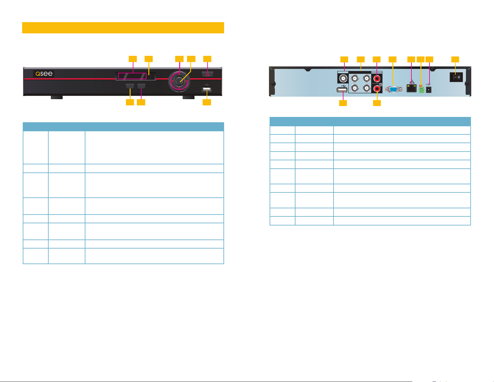
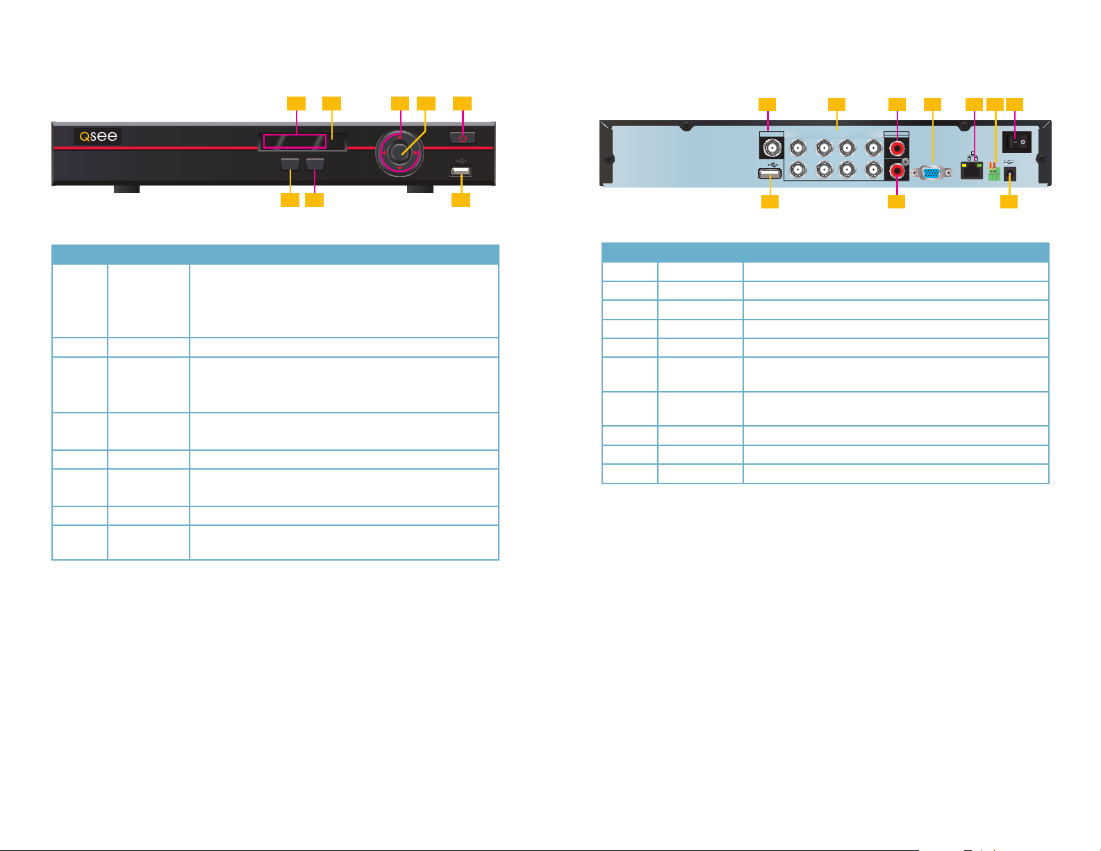
Number Item Function
Alarm: Not functional on this model
1 Status Lights
2 IR Sensor Infrared Receiver for Remote Control
Directional
3
Buttons
4 Enter Button
5 Power Button Puts DVR into Standby mode or wakes it up.
Function
6
Button
7 Escape Button Exit any menu or current operation
8 USB Port
If the user is logged out, pressing the Enter button will open the Login window. Pressing the
Function button will open the Virtual Keyboard which can be navigated using the directional
buttons. Click Enter to enter a keystroke. Press the Escape button to close the Virtual Key-
board and then press the Enter button to submit your password.
Net: Red light indicates that network connection is lost
HDD: Red light indicates that hard drive is operating
Power: Red light indicates that DVR is powered up
Navigate through menus.
Change selections in pull down menus (Up/Down buttons)
Toggle settings (Up/Down buttons)
Viewing Mode: Go To Menu
In Menu: Acts as mouse click
Single Channel Viewing Mode: Opens Color Adjustment
Virtual Keyboard: Backspace function
For use with flash drive when backing up or updating
firmware. Not for use with mouse.
9 10
Number Item Function
1 Video Out BNC Connector to television
2 Video In Ports BNC Connectors for video feed from cameras (4)
3 Audio Out RCA Connector for audio output
4 VGA Video Out To connect to a VGA monitor (19” or larger)
5 Network Ethernet cable connection to network
6 RS485
7 Power Input Connect 12V DC power supply here
8 Power Switch
9 USB Connect the USB mouse to this port
10 Audio In RCA input for audio feed from microphone
Connect the data cables for a PTZ camera into these ports to
control it. “A” is positive (+) and “B” is negative (-).
Turns DVR on or off. Use Shutdown menu function or front
panel power button before switching off.
10 11
QC448
Front Panel
Rear Panel
1 2
ALARM POWERHDDNET
QC484
ESCFN
76 8
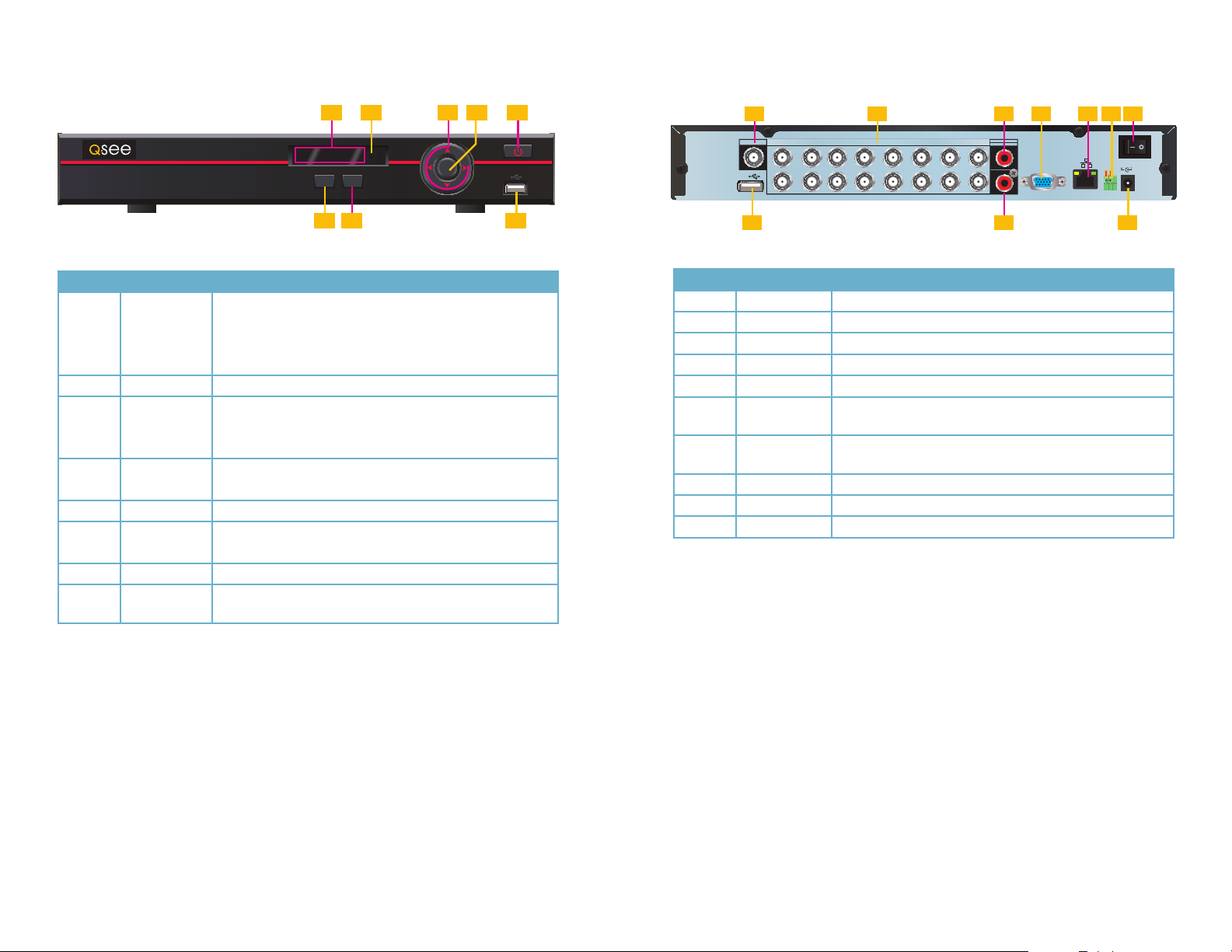
Number Item Function
Alarm: Not functional on this model
1 Status Lights
2 IR Sensor Infrared Receiver for Remote Control
Directional
3
Buttons
4 Enter Button
5 Power Button Puts DVR into Standby mode or wakes it up.
Function
6
Button
7 Escape Button Exit any menu or current operation
8 USB Port
Net: Red light indicates that network connection is lost
HDD: Red light indicates that hard drive is operating
Power: Red light indicates that DVR is powered up
Navigate through menus.
Change selections in pull down menus (Up/Down buttons)
Toggle settings (Up/Down buttons)
Viewing Mode: Go To Menu
In Menu: Acts as mouse click
Single Channel Viewing Mode: Opens Color Adjustment
Virtual Keyboard: Backspace function
For use with flash drive when backing up or updating
firmware. Not for use with mouse.
3 54
ENTER
1
VIDEO OUT
1234567
2 3 4 5 6 7
VIDEO IN
AUDIO OUT
AUDIO IN
8
VGA
98 10
Number Item Function
1 Video Out BNC Connector to television
2 Video In Ports BNC Connectors for video feed from cameras (8)
3 Audio Out RCA Connector for audio output
4 VGA Video Out To connect to a VGA monitor (19” or larger)
5 Network Ethernet cable connection to network
6 RS485
7 Power Switch
8 USB Connect the USB mouse to this port
9 Audio In RCA input for audio feed from microphone
10 Power Input Connect 12V DC power supply here
Connect the data cables for a PTZ camera into these ports to
control it. “A” is positive (+) and “B” is negative (-).
Turns DVR on or off. Use Shutdown menu function or front
panel power button before switching off.
DC 12V
AB
If the user is logged out, pressing the Enter button will open the Login window. Pressing the
Function button will open the Virtual Keyboard which can be navigated using the directional
buttons. Click Enter to enter a keystroke. Press the Escape button to close the Virtual Keyboard and then press the Enter button to submit your password.
12 13
QC4316
Front Panel
Rear Panel
1 2
ALARM POWERHDDNET
QC484
ESCFN
76 8
Number Item Function
Alarm: Not functional on this model
1 Status Lights
2 IR Sensor Infrared Receiver for Remote Control
Directional
3
Buttons
4 Enter Button
5 Power Button Puts DVR into Standby mode or wakes it up.
Function
6
Button
7 Escape Button Exit any menu or current operation
8 USB Port
Net: Red light indicates that network connection is lost
HDD: Red light indicates that hard drive is operating
Power: Red light indicates that DVR is powered up
Navigate through menus.
Change selections in pull down menus (Up/Down buttons)
Toggle settings (Up/Down buttons)
Viewing Mode: Go To Menu
In Menu: Acts as mouse click
Single Channel Viewing Mode: Opens Color Adjustment
Virtual Keyboard: Backspace function
For use with flash drive when backing up or updating
firmware. Not for use with mouse.
3 54
ENTER
1 2
VIDEO OUT
123456789101112131415
VIDEO IN
3 4 5 6 7
AUDIO OUT
AUDIO IN
16
VGA
9 108
Number Item Function
1 Video Out BNC Connector to television
2 Video In Ports BNC Connectors for video feed from cameras (16)
3 Audio Out RCA Connector for audio output
4 VGA Video Out To connect to a VGA monitor (19” or larger)
5 Network Ethernet cable connection to network
6 RS485
7 Power Switch
8 USB Connect the USB mouse to this port
9 Audio In RCA input for audio feed from microphone
10 Power Input Connect 12V DC power supply here
Connect the data cables for a PTZ camera into these ports to
control it. “A” is positive (+) and “B” is negative (-).
Turns DVR on or off. Use Shutdown menu function or front
panel power button before switching off.
DC 12V
AB
If the user is logged out, pressing the Enter button will open the Login window. Pressing the
Function button will open the Virtual Keyboard which can be navigated using the directional
buttons. Click Enter to enter a keystroke. Press the Escape button to close the Virtual Keyboard and then press the Enter button to submit your password.
14 15
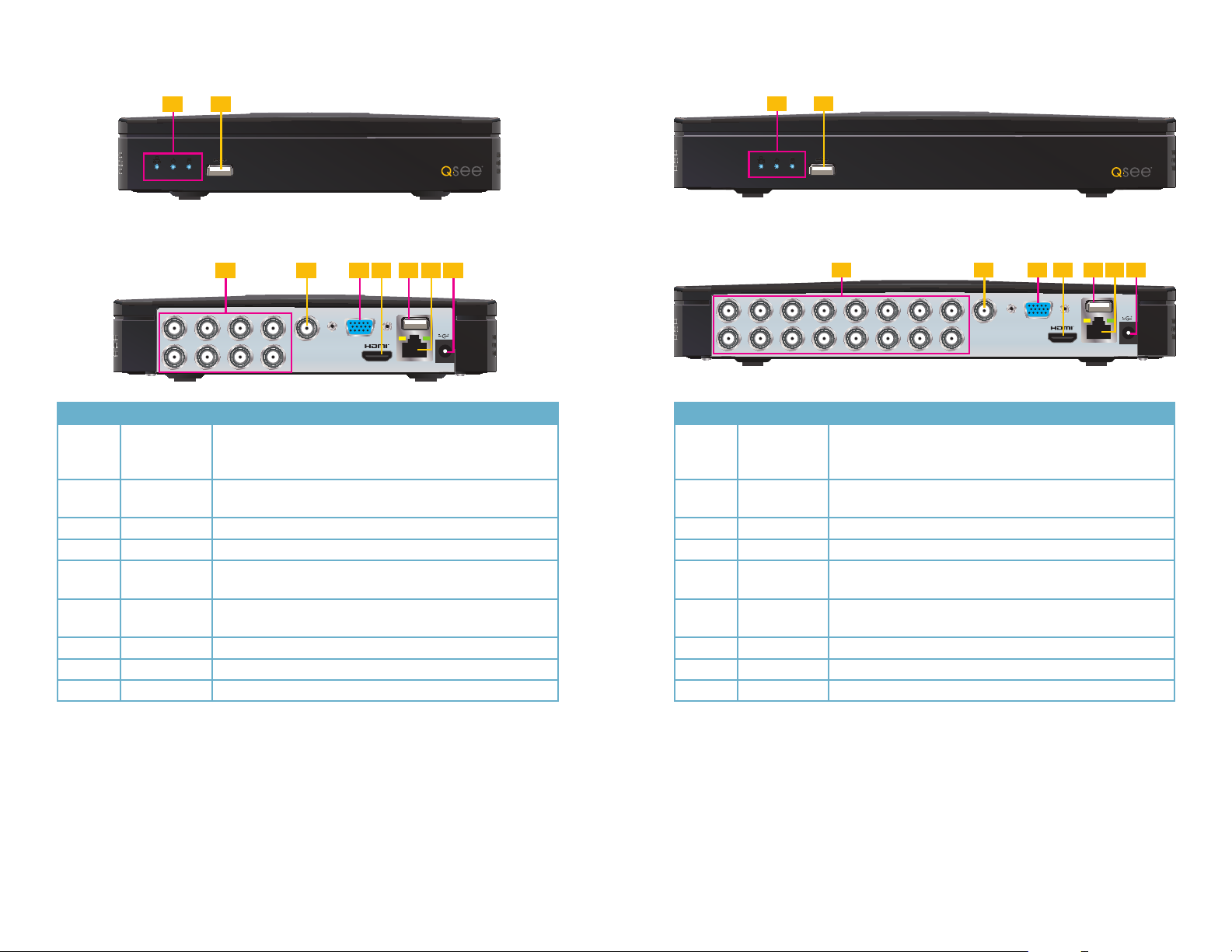
QC304
Front Panel
QC308
Front Panel
1 2 1 2
Rear Panel Rear Panel
3
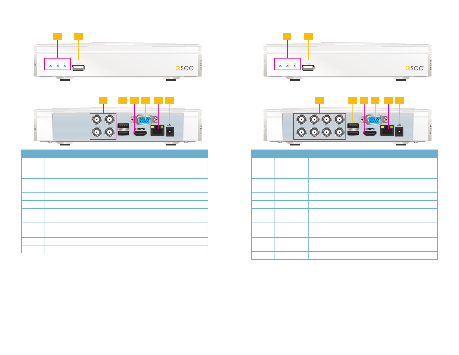
Number Item Function
These show the status of the network connection, power and
1 Status Lights
2 USB Port
3 Video In Ports BNC Connectors for video feed from cameras (4)
4 USB Connect the USB mouse to one of these ports
HDMI Video
5
Out
VGA Video
6
Out
7 Network Ethernet cable connection to network.
8 Power Input Connect 12V DC power supply here
hard drive respectively. The Network and Power lights will
normally be on. The Hard Drive light will normally be off.
For use with flash drive when backing up or updating
firmware. Not for use with mouse.
To connect to an HD display (21.5” or larger)
To connect to a VGA monitor (21.5” or larger)
5 7 84 6
VGA
DC 12V
3
Number Item Function
These show the status of the network connection, power and
1 Status Lights
2 USB Port
3 Video In Ports BNC Connectors for video feed from cameras (8)
4 USB Connect the USB mouse to one of these ports
HDMI Video
5
Out
VGA Video
6
Out
7 Network
8 Power Input Connect 12V DC power supply here
hard drive respectively. The Network and Power lights will
normally be on. The Hard Drive light will normally be off.
For use with flash drive when backing up or updating
firmware. Not for use with mouse.
To connect to an HD display (21.5” or larger)
To connect to a VGA monitor (21.5” or larger)
Ethernet cable connection to network.
5 7 84 6
VGA
DC 12V
16 17
QC3016
Front Panel
QC524
Front Panel
1 2
Rear Panel Rear Panel
5 7 94 6 83
VGA
DC 12V
1 2
5 7 94 6 83
VGA
DC 12V
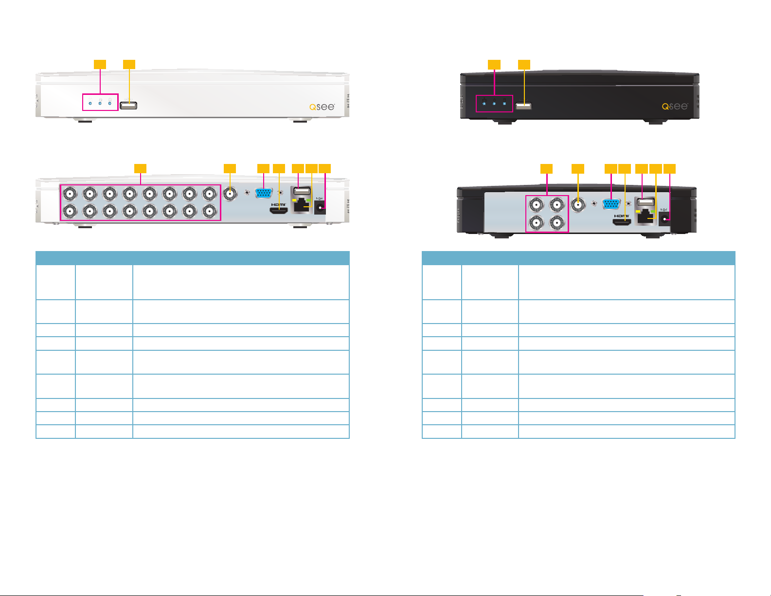
Number Item Function
These show the status of the network connection, power and
1 Status Lights
hard drive respectively. The Network and Power lights will
normally be on. The Hard Drive light will normally be off.
2 USB Port
For use with flash drive when backing up or updating
firmware. Not for use with mouse.
3 Video In Ports BNC Connectors for video feed from cameras (16)
4 Video Out BNC Connector to television
5
6
VGA Video
Out
HDMI Video
Out
To connect to a VGA monitor (21.5” or larger)
To connect to an HD display (21.5” or larger)
7 USB Connect the USB mouse to this port
8 Network Ethernet cable connection to network.
9 Power Input Connect 12V DC power supply here
Number Item Function
These show the status of the network connection, power and
1 Status Lights
hard drive respectively. The Network and Power lights will
normally be on. The Hard Drive light will normally be off.
2 USB Port
For use with flash drive when backing up or updating
firmware. Not for use with mouse.
3 Video In Ports BNC Connectors for video feed from cameras (4)
4 Video Out BNC Connector to television
5
6
VGA Video
Out
HDMI Video
Out
To connect to a VGA monitor (21.5” or larger)
To connect to an HD display (21.5” or larger)
7 USB Connect the USB mouse to this port
8 Network Ethernet cable connection to network.
9 Power Input Connect 12V DC power supply here
18 19
QC588
Front Panel
1 2
QC5416
Front Panel
1 2
Rear Panel
5 7 94 6 83
VGA
Number Item Function
These show the status of the network connection, power and
1 Status Lights
2 USB Port
3 Video In Ports BNC Connectors for video feed from cameras (8)
4 Video Out BNC Connector to television
VGA Video
5
Out
HDMI Video
6
Out
7 USB Connect the USB mouse to this port
8 Network Ethernet cable connection to network.
9 Power Input Connect 12V DC power supply here
hard drive respectively. The Network and Power lights will
normally be on. The Hard Drive light will normally be off.
For use with flash drive when backing up or updating
firmware. Not for use with mouse.
To connect to a VGA monitor (21.5” or larger)
To connect to an HD display (21.5” or larger)
DC 12V
Rear Panel
5 7 94 6 83
VGA
Number Item Function
These show the status of the network connection, power and
1 Status Lights
2 USB Port
3 Video In Ports BNC Connectors for video feed from cameras (16)
4 Video Out BNC Connector to television
VGA Video
5
Out
HDMI Video
6
Out
7 USB Connect the USB mouse to this port
8 Network Ethernet cable connection to network.
9 Power Input Connect 12V DC power supply here
hard drive respectively. The Network and Power lights will
normally be on. The Hard Drive light will normally be off.
For use with flash drive when backing up or updating
firmware. Not for use with mouse.
To connect to a VGA monitor (21.5” or larger)
To connect to an HD display (21.5” or larger)
DC 12V
20 21
2.2 MOUSE CONTROL
SYSTEM LOGIN
User Name
Password
admin
This DVR can be controlled through the USB mouse, the remote control or by using the
buttons on the front panel of the device. We have found that the majority of our customers
prefer to operate their DVRs using the USB mouse because of its ease of use and flexibility
and our manual is set up with this in mind. The remote control allows you to perform most of
the day-to-day functions from a convenient distance. It functions as a typical remote control
with additional buttons allowing you to navigate through menus and control functions. We
recommend that you configure your DVR using the mouse controls, reserving the remote
control for operations such as live viewing, file search and playback.
The mouse operates in a manner similar to how it is used on a conventional computer; pointand-click, right-click, double click and so on. How these functions are used is based on the
context of where they are used. Some examples are:
LEFT CLICK: Selecting an item
Opening a menu
Checking a box or motion detection status
Selecting letters, numbers or symbols on the virtual keyboard.
DOUBLE CLICK: Selecting an event for playback
Selecting a screen to zoom into from multi-screen mode
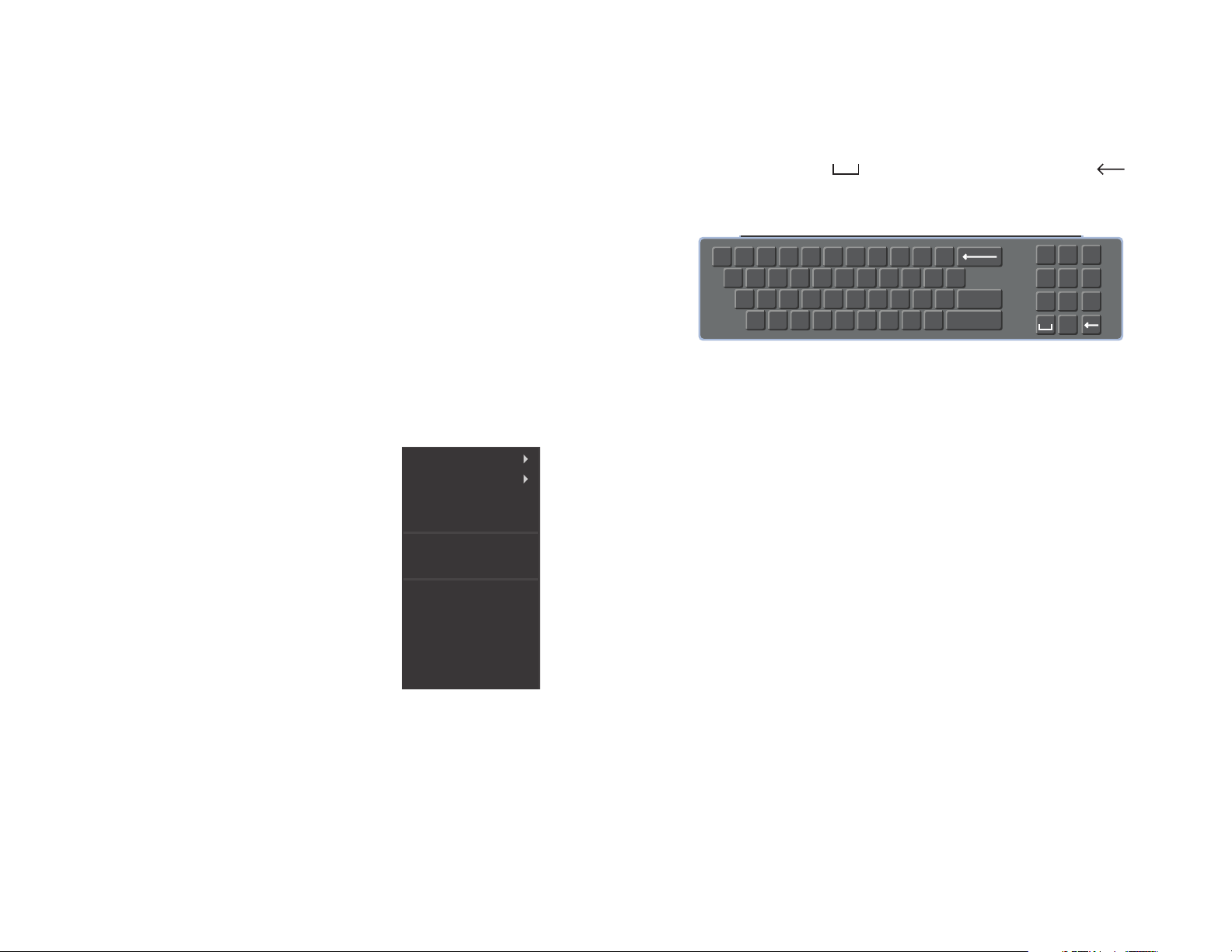
VIRTUAL KEYBOARD
Whenever a menu field requires text - such as a password, new user name, or other setting
- clicking on that field will bring up the virtual keyboard. It operates as regular keyboard using
the point and click function of the mouse to select individual characters. Clicking the shift key
allows access to the upper-case characters.
Spaces are entered using the symbol and characters are deleted with the key.
Clicking Enter or clicking outside of the keyboard will close it.
! ? @ # $ % ^ + * - _
q w e r t y u i o p |
a s d f g h j k l ; Enter
z x c v b n m , .
PICTURE 2-2
Shift
1 2 3
54 6
87 9
0
RIGHT CLICK
Opens Pop-Up
Exits any window. Exits
any menu or reopens
previous menu.
Shortcut Menu. The
options available especially multi-channel
viewing options - will
vary by model
View 1
View 4
View 8
View 9
Pan/Tilt/Zoom
Color Setting
Search
Record Status
Tour Setup
Multi-Preview
MOUSE WHEEL Page up or page down
Switch items in check box
Increase or decrease numerical value in numerical input box
CLICK-AND-DRAG Select motion detection zone
Select privacy mask zone
Main Menu
PICTURE 2-1
22 23
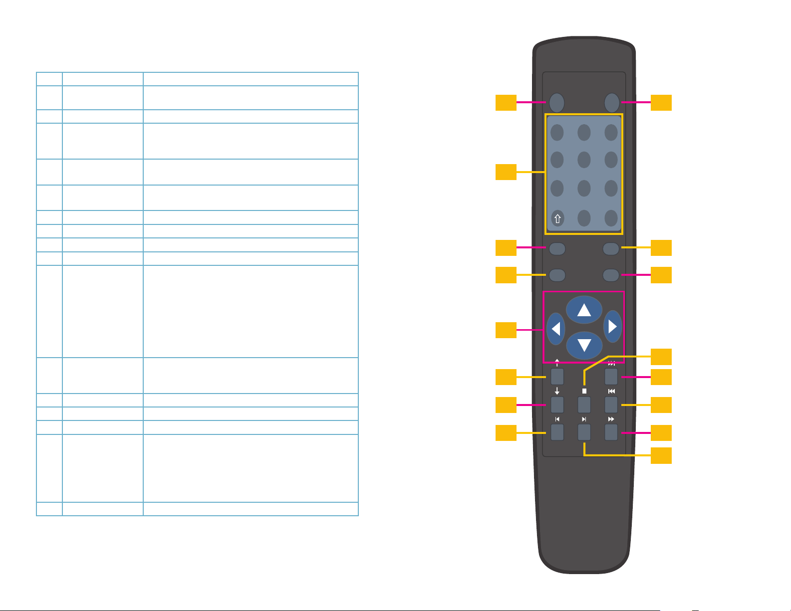
2.3 REMOTE CONTROL
The buttons on the Remote Control operate in the same manner as on a conventional DVR
remote. Some buttons have multiple functions depending on which menu is being accessed.
Num Name Function
1 Multiple-window
switch
2 0-9 number key Input password, channel or switch channel.
3 Record Start or stop recording manually
4 Enter /Menu key Go to default button
5 Direction keys Switch current activated control, go to left or right.
6 Previous In playback mode, playback the previous video.
7 Next In playback mode, playback the next video.
8 Slow Play Multiple slow play speeds or normal playback.
9 Address Click to input device serial number
10 Function/Aux Key In 1-channel monitor mode: pop up assistant function
11 Escape/Cancel Go back to previous menu or cancel current operation
12 Stop In playback mode, stop current playback.
13 Forward Various forward speeds and normal speed playback.
14 Backward Various backward speeds and normal speed playback.
15 Play/Pause Reverse playback or paused mode, click this button to
16 Fast Forward Various fast speeds and normal playback.
Switch between multiple-window and one-window view
In record interface, working with the direction buttons to
select the channel to record
Go to the menu
In playback mode, it is to control the playback process bar.
In motion detection interface, functions as a directional key
to complete setup
Backspace: Press for 1.5 seconds to clear all contents in
current text box.
In HDD information interface, used to switch between HDD
record time and other information
Special combined operation in some menus.
(close upper interface or control)
In playback mode, it goes to real-time monitor mode.
realize normal playback.
In normal playback click this button to pause or resume
playback.
In real-time monitor mode, click this button to enter video
search menu.
1
2
3
4
5
6
7
8
Mult Add
., ABC DEF
2
1
GHI JKL MNO
5
4
PQRS TUV WXYZ
8
7
0
Record Fn
Enter/Menu
DVR
9
3
6
9
-/--
10
Esc
11
12
13
14
15
16
PICTURE 2-3
24 25
2.4 VIDEO DISPLAY
QC-Series DVRs can use a television or a 19” or larger monitor as a main video display.
Certain models also provide the option of using a high definition display, such as an HDTV.
A video display is not needed for day to day use of your DVR if you are only monitoring it
remotely via a mobile device or using a computer, but one is needed for initial setup. It should
also be noted that, at present, it is not possible to change settings on the DVR itself using
the QC View mobile remote viewing apps and certain settings cannot be changed using the
remote monitoring software on the computer.
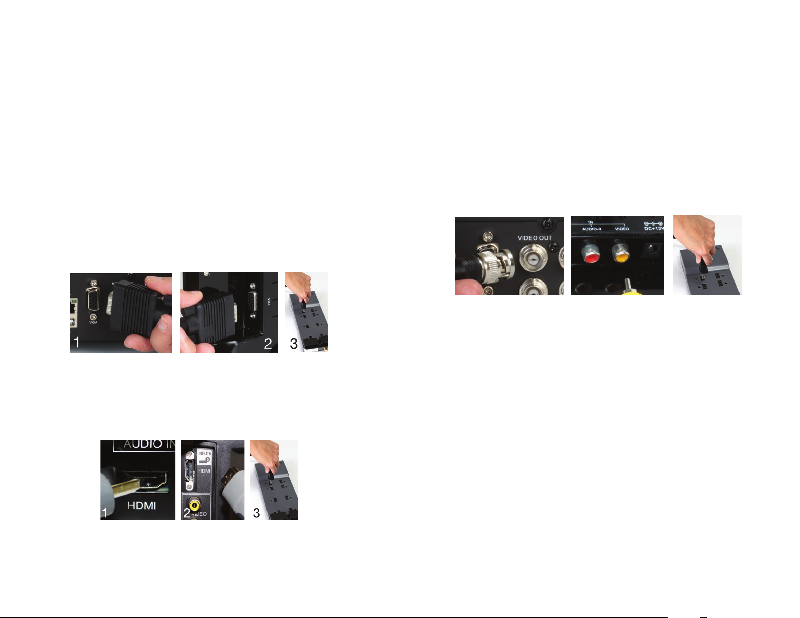
CONNECTING A VIDEO DISPLAY
Instructions on connecting a desired video display are included in the Quick Start Poster that
came with your system but are included here for your convenience.
VGA Monitor
Using a standard VGA monitor - the type used with most computers - with your DVR is the
preferred method and the DVR is configured with this in mind. Due to resolution restrictions,
you must use a monitor that has at least a 19” diagonal display. This information is typically
found on the back of the monitor if you are uncertain.
STEP 1. Plug a VGA cable into the port marked “VGA” on the back of the DVR.
STEP 2. Plug the other end of the VGA cable into the similar port on the back of the monitor.
STEP 3. Plug the monitor’s power cable into the surge protector.
PICTURE 2-4
High Definition Television
Some QC-Series DVRs include an HDMI video out port allowing you to use a high definition
television or other display that has an HDMI video input.
STEP 1. Plug an HDMI cable into the “HDMI” port on the back of the DVR.
STEP 2. Plug the other end into the “HDMI” port on the television.
STEP 3. Plug the television’s power cable into a surge protector.
Changing Display Resolution
You can adjust the DVR to optimize its output to best match the capabilities of your monitor or
HD display through the following steps:
STEP 1. Open the Main Menu.
STEP 2. Click on the Settings icon to open the Settings window.
STEP 3. Click on the Display icon to open the Display window
STEP 4. Choose your desired resolution from the Resolution pull-down menu.
STEP 5. Click on Save to save your settings and then click Exit.
Television
A third option for a video display is any television with an RCA video input. The DVR’s Video
Out port uses a BNC type connector for coaxial cable. Depending on model, your DVR may
include a BNC-to-RCA cable or adapter. The latter converts the BNC jack to an RCA port
allowing you to connect the DVR to the television using a readily available RCA cable.
1 2 3
PICTURE 2-6
STEP 1. Connect a BNC-to-RCA cable to the “Video Out” port on the back of the DVR.
STEP 2. Plug the RCA end into the “Video In” port on the television.
STEP 3. Plug the television’s power cable into a surge protector.
PICTURE 2-5
2726
 Loading...