


 Loading...
ES2486dc
User Guide
Document Version: 5 04/02/2020
ES2486dc User Guide
Contents |
|
1. Preface |
|
About This Guide.......................................................................................................................................... |
3 |
Audience....................................................................................................................................................... |
3 |
Document Conventions................................................................................................................................ |
3 |
2. Product Overview |
|
About the ES2486dc..................................................................................................................................... |
4 |
Hardware Specifications............................................................................................................................... |
4 |
Package Contents........................................................................................................................................ |
7 |
Components................................................................................................................................................. |
7 |
Front Panel............................................................................................................................................... |
8 |
Front Panel LEDs..................................................................................................................................... |
8 |
Front Panel Buttons.................................................................................................................................. |
9 |
OLED Panel Behavior............................................................................................................................ |
10 |
Rear Panel.............................................................................................................................................. |
13 |
Rear Panel LEDs.................................................................................................................................... |
15 |
Storage Controller Power Button............................................................................................................ |
17 |
Reset Button........................................................................................................................................... |
17 |
Battery Backup Unit................................................................................................................................ |
18 |
System Board......................................................................................................................................... |
18 |
Drive Numbering..................................................................................................................................... |
19 |
Installation Requirements........................................................................................................................... |
20 |
Setting Up the NAS..................................................................................................................................... |
20 |
3. Installation and Configuration |
|
Hardware Installation.................................................................................................................................. |
22 |
Removing a Storage Controller.............................................................................................................. |
22 |
Installing a Storage Controller................................................................................................................ |
23 |
Drive Installation..................................................................................................................................... |
24 |
Installing Expansion Cards..................................................................................................................... |
27 |
Replacing Memory Modules................................................................................................................... |
29 |
Replacing the Fan Module...................................................................................................................... |
31 |
Hot-Swapping Redundant Power Supply Units...................................................................................... |
32 |
Replacing the Battery Backup Unit......................................................................................................... |
34 |
Expansion Unit Installation..................................................................................................................... |
35 |
Rail Kits.................................................................................................................................................. |
40 |
QES Installation.......................................................................................................................................... |
40 |
Installing QES Using a Static IP Address............................................................................................... |
41 |
Installing QES Using a Dynamic IP Address.......................................................................................... |
42 |
Installing QES Using Manual Setup....................................................................................................... |
43 |
Service Port Configuration.......................................................................................................................... |
45 |
Storage Controller Service Port.............................................................................................................. |
45 |
Expansion Unit Service Port................................................................................................................... |
46 |
Management Port Configuration................................................................................................................. |
47 |
Multipath I/O Network Configuration........................................................................................................... |
48 |
4. Troubleshooting |
|
Forcing Qfinder Pro to Locate the NAS...................................................................................................... |
50 |
Hot-swapping Failed Drives........................................................................................................................ |
50 |
Support and Other Resources.................................................................................................................... |
51 |
1
5. Glossary |
|
QES............................................................................................................................................................ |
52 |
Qfinder Pro................................................................................................................................................. |
52 |
6. Notices |
|
Limited Warranty......................................................................................................................................... |
53 |
Disclaimer................................................................................................................................................... |
53 |
GNU Public License.................................................................................................................................... |
53 |
CE Notice.................................................................................................................................................... |
61 |
FCC Notice................................................................................................................................................. |
61 |
VCCI Notice................................................................................................................................................ |
61 |
BSMI Notice................................................................................................................................................ |
62 |
SJ/T 11364-2006......................................................................................................................................... |
62 |
2

ES2486dc User Guide
1. Preface
About This Guide
This guide provides information on the QNAP ES2486dc NAS and step-by-step instructions on installing the hardware. It also provides instructions on basic operations and troubleshooting information.
Audience
This document is intended for storage administrators. This guide assumes that the user is knowledgeable and qualified to install, maintain, and troubleshoot issues involving servers, server components, and storage systems. This guide also assumes that the user is trained to recognize hazards, including the appropriate actions the user needs to take to prevent personal injury and damage to data and property.
Document Conventions
Symbol |
Description |
|
Notes provide default configuration settings and other supplementary |
|
information. |
|
|
|
Important notes provide information on required configuration settings and other |
|
critical information. |
|
|
|
Tips provide recommendations or alternative methods of performing tasks or |
|
configuring settings. |
|
|
|
Warnings provide information that, when ignored, may result in potential loss, |
|
injury, or even death. |
|
|
Preface 3

ES2486dc User Guide
2. Product Overview
This chapter provides basic information about the QNAP ES2486dc NAS.
About the ES2486dc
The ES2486dc is a dual-controller ZFS NAS designed to deliver a scalable platform for enterprise-level solutions. It is equipped with a powerful multi-core processor, AES-NI hardware encryption engine, and both USB 3.0 and 10GbE ports, allowing it to deliver optimal performance for enterprise users. In addition to 24bay capacity, the ES2486dc supports redundant storage controllers and power supplies to provide the necessary reliability, serviceablility, and read/write speeds.
Hardware Specifications
Warning
•If your QNAP product has hardware defects, return the product to QNAP or a QNAPauthorized service center for maintenance or replacement. Any attempt to repair or perform maintenance procedures on the product by you or an unauthorized third-party invalidates the warranty.
•QNAP is not responsible for any damage or data loss caused by unauthorized modifications and installation of unsupported third-party applications.
For details, see the QNAP Warranty Terms and Conditions.
Ordering P/N |
CPU |
Memory |
Power supply |
ES2486dc-2142IT-96G |
Intel® Xeon® D-2142IT |
96 GB (48 GB per |
Redundant |
|
|
controller) |
|
ES2486dc-2142IT-128G |
Intel® Xeon® D-2142IT |
128 GB (64 GB per |
Redundant |
|
|
controller) |
|
|
|
|
|
Component |
ES2486dc-2142IT-96G |
ES2486dc-2142IT-128G |
Processor |
|
|
|
|
|
CPU |
Intel® Xeon® D-2142IT |
|
|
|
|
Frequency |
8-core/16-thread 1.90 GHz base/3.0 GHz burst |
|
|
|
|
Architecture |
x86 64-bit |
|
|
|
|
Encryption engine |
AES-NI |
|
|
|
|
Memory |
|
|
|
|
|
Pre-installed memory |
48 GB RAM: 4 x 4 GB RDIMM |
64 GB RAM: 4 x 16 GB RDIMM |
|
DDR4 ECC and 4 x 8 GB RDIMM |
DDR4 ECC |
|
DDR4 ECC |
|
Product Overview 4

ES2486dc User Guide
Component |
|
|
ES2486dc-2142IT-96G |
|
ES2486dc-2142IT-128G |
|
Memory slots |
8 x R-DIMM or LR-DIMM DDR4 per controller |
|||||
|
|
|
Important |
|
||
|
|
|
|
|||
|
|
|
• |
Use only QNAP memory modules to maintain |
||
|
|
|
|
system performance and stability. For NAS devices |
||
|
|
|
|
with more than one memory slot, use QNAP |
||
|
|
|
|
modules with identical specifications. |
||
|
|
|
• |
Using unsupported modules may degrade |
||
|
|
|
|
performance, cause errors, or prevent the |
||
|
|
|
|
operating system from starting. |
||
|
|
|
• |
You can only use one type of dual in-line memory |
||
|
|
|
|
module (DIMM) at a time. Do not use registered |
||
|
|
|
|
DIMM (RDIMM) with load-reduction DIMM |
||
|
|
|
|
(LRDIMM) memory. |
|
|
|
|
|
||||
Maximum memory |
512 GB RAM: 8 x 64 GB |
|
||||
|
|
|
||||
Flash memory |
4 GB (dual-boot OS protection) |
|
||||
|
|
|
||||
Cache for Copy-to-Flash |
64 GB per controller |
|
||||
|
|
|
|
|
|
|
Storage |
|
|
|
|
|
|
|
|
|
||||
Drive bays |
24 x 2.5-inch SAS 12 Gbps |
|
||||
|
|
|
Note |
|
||
|
|
|
|
|||
|
|
|
The interface is backward compatible with SAS 6 Gbps |
|||
|
|
|
drives. |
|
||
|
|
|
|
|||
Drive compatibility |
• |
2.5-inch SATA hard disk drives |
|
|||
|
• |
2.5-inch SATA solid-state drives |
|
|||
|
• |
2.5-inch SAS hard disk drives |
|
|||
|
• |
2.5-inch SAS solid-state drives |
|
|||
|
|
|
Tip |
|
|
|
|
|
|
|
|
|
|
|
|
|
• |
For the list of compatible drive models, go to |
||
|
|
|
|
https://www.qnap.com/compatibility. |
||
|
|
|
• |
A QDA-SA3 drive adapter is required for installing |
||
|
|
|
|
SATA HDD/SSD. For more details, see QDA-SA3 |
||
|
|
|
|
Quick Installation Guide. |
|
|
|
|
|
||||
SSD cache acceleration support |
2.5-inch drive bays: 1 to 24 |
|
||||
|
|
|
|
|
|
|
Network |
|
|
|
|
|
|
|
|
|
||||
10 Gigabit Ethernet ports |
4 x 10GbE SFP+ ports per controller |
|
||||
|
|
|
||||
Gigabit Ethernet ports |
3 x GbE RJ45 ports per controller |
|
||||
|
|
|
|
|
|
|
External I/O Ports & Expansion Slots |
|
|
|
|
|
|
|
|
|
||||
PCIe slots |
2 x PCIe 3.0 x8 slots per controller |
|
||||
|
|
|
Tip |
|
|
|
|
|
|
|
|
|
|
|
|
|
For the list of compatible expansion cards, go to |
|||
|
|
|
https://www.qnap.com/compatibility. |
|||
|
|
|
|
|
|
|
Product Overview 5

ES2486dc User Guide
Component |
|
|
ES2486dc-2142IT-96G |
|
ES2486dc-2142IT-128G |
|
USB ports |
2 x USB 3.0 Type-A ports per controller |
|
||||
|
|
|
|
|
|
|
Interface |
|
|
|
|
|
|
|
|
|
|
|
||
Buttons |
NAS: |
|
|
|
||
|
• |
Power |
|
|
|
|
|
• |
OLED panel power button |
|
|||
|
Storage controllers: |
|
||||
|
• |
Power |
|
|
|
|
|
• |
Reset |
|
|
|
|
|
|
|
|
|
|
|
Dimensions |
|
|
|
|
|
|
|
|
|
||||
Form factor |
2U Rackmount |
|
||||
|
|
|
||||
Dimensions (H x W x D) |
88.3 x 483 x 545.1 mm |
|
||||
|
(34.76 x 190.16 x 241.61 in) |
|
||||
|
|
|
||||
Net weight |
27.41 kg (60.43 lbs) |
|
||||
|
|
|
|
|
|
|
Other |
|
|
|
|
|
|
|
|
|
|
|
||
Rail compatibility |
RAIL-E03 |
|
|
|
||
|
|
|
Note |
|
||
|
|
|
|
|||
|
|
|
• |
You can find installation information in the rail kit |
||
|
|
|
|
package. |
|
|
|
|
|
• |
For details, go to http://srcqnap.qnap.com.tw/en/ |
||
|
|
|
|
product/rail-kit. |
|
|
|
|
|
||||
Power supply unit |
2 x 700W, 90-264V AC, 50/60 Hz |
|
||||
|
|
|
||||
System battery |
CR2032 lithium battery (3V, 225 mAh) |
|
||||
|
|
|
Warning |
|
||
|
|
|
|
|||
|
|
|
To avoid potential battery explosion, causing injury or |
|||
|
|
|
damage to components, ensure that you replace the |
|||
|
|
|
existing battery with a battery of the same type. |
|||
|
|
|
Important |
|
||
|
|
|
|
|||
|
|
|
Dispose of used batteries according to local |
|||
|
|
|
regulations or the instructions of the battery |
|||
|
|
|
manufacturer. |
|
||
|
|
|
||||
Hot-swappable battery backup unit |
2 x 10.8V, 2200 mAh |
|
||||
|
|
|
|
|
||
Sound level |
60.9 db(A) |
|
|
|
||
|
|
|
Note |
|
||
|
|
|
|
|||
|
|
|
The sound level was tested at a bystander position, |
|||
|
|
|
which is within one meter of the NAS. The test NAS |
|||
|
|
|
operated at low speed with the maximum number of |
|||
|
|
|
drives installed. |
|
||
|
|
|
|
|
|
|
Product Overview 6
ES2486dc User Guide
Component |
|
|
ES2486dc-2142IT-96G |
|
ES2486dc-2142IT-128G |
|
Hot-swappable fan module |
System: 60 x 60 x 38 mm, 12V DC fan |
|
||||
|
|
|
Warning |
|
||
|
|
|
|
|||
|
|
|
• |
To avoid potential injury or damage to components, |
||
|
|
|
|
do not touch the fans while the NAS is connected |
||
|
|
|
|
to a power source. |
|
|
|
|
|
• |
To ensure proper cooling, replacement of the fan |
||
|
|
|
|
should be completed within 10 seconds. |
||
|
|
|
||||
Operating temperature |
0˚C to 40˚C (32˚F to 104˚F) |
|
||||
|
|
|
||||
Relative humidity |
• |
Non-condensing relative humidity: 5% to 95% |
||||
|
• |
Wet-bulb temperature: 27˚C (80.6˚F) |
|
|||
|
|
|
|
|
|
|
Tip
Model specifications are subject to change without prior notice. To see the latest specifications, go to https://www.qnap.com.
Package Contents
Item |
Quantity |
ES2486dc |
1 |
|
|
Power cord |
2 |
|
|
Ethernet cables |
Cat 5e cables: 6 |
|
|
Screws for 2.5-inch drives |
96 |
|
|
Rail kit |
1 x RAIL-E03 |
Note
You can find installation information in the rail kit package.
Quick Installation Guide (QIG) |
1 |
Components
Product Overview 7
ES2486dc User Guide
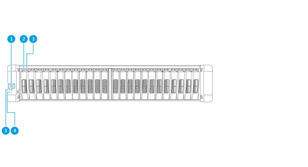
Front Panel
No. |
Component |
No. |
Component |
1 |
OLED panel |
4 |
System status LED |
|
|
|
|
2 |
Drive activity LED |
5 |
System power LED |
|
|
|
|
3 |
Drive status LED |
- |
- |
|
|
|
|
Front Panel LEDs
The front panel LEDs indicate system status and related information when the NAS is powered on. The following LED information applies only when the drive is correctly installed and when the NAS is connected to the network.
For details on the location of the LEDs, see Front Panel.
LED |
Status |
Description |
System power |
Blue |
The system is powered on. |
|
|
|
Product Overview 8
ES2486dc User Guide
LED |
Status |
|
Description |
System status |
Green |
The system is operating normally. |
|
|
|
|
|
|
Red |
• |
Displays detected system errors or warnings |
|
|
|
(e.g. degraded RAID mode, memory failure, fan/ |
|
|
|
power supply failure, system/disk temperature |
|
|
|
too high, storage pool reaching threshold value). |
|
|
|
For details, see the QES User Guide. |
|
|
• |
The system is performing takeover. The dual |
|
|
|
active-active controller system enables a single |
|
|
|
controller to take over the pool disk resources |
|
|
|
owned by the other controller in the event of a |
|
|
|
controller failure. Takeovers can be initiated |
|
|
|
manually or be set up with the automatic system |
|
|
|
failover protection. For details, see the QES |
|
|
|
User Guide. |
|
|
• |
The power supply unit is disconnected. |
|
|
|
|
Drive status |
Green |
The drive can be accessed. |
|
|
|
|
|
|
Flashing green slowly |
The QES Storage Manager Locate command is |
|
|
|
enabled and is identifying the drive. |
|
|
|
|
|
|
Red |
A drive read/write error has occurred. |
|
|
|
|
|
|
Off |
The drive is not installed. |
|
|
|
|
|
Drive activity |
Flashing green |
No drive activity has been detected. |
|
|
continuously or slowly |
|
|
|
Flashing green |
The high activity on drive or drive being configured is |
|
|
|
part of an array. |
|
|
|
|
|
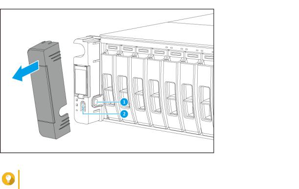
Front Panel Buttons
Tip
Remove the front panel cover to access the front panel buttons.
Product Overview 9
ES2486dc User Guide
No. |
Component |
No. |
Component |
1 |
OLED panel power button |
2 |
Power button |
|
|
|
|
Operation |
User Action |
|
|
|
Result |
Power on NAS |
Press the power button. |
• |
Both storage controllers power on. |
||
|
|
• |
All storage and management services are |
||
|
|
|
disabled. |
||
|
|
|
|
Tip |
|
|
|
|
|
|
|
|
|
|
|
• |
System startup takes 10 to 15 |
|
|
|
|
|
minutes, depending on the number |
|
|
|
|
|
of installed drives and connected |
|
|
|
|
|
devices. Check the rear panel LEDs |
|
|
|
|
|
to determine the startup status. For |
|
|
|
|
|
details, see Rear Panel LEDs. |
|
|
|
|
• |
This button can only be used to |
|
|
|
|
|
power on the two storage |
|
|
|
|
|
controllers. Use the respective rear |
|
|
|
|
|
panel storage controller power |
|
|
|
|
|
button to power off the storage |
|
|
|
|
|
controllers. For details, see Storage |
|
|
|
|
|
Controller Power Button. |
|
|
|
|||
Power on OLED |
Press the OLED panel power |
The OLED display powers on. |
|||
display |
button. |
|
|
|
|
|
|
|
|||
Power off OLED |
Press the OLED panel power |
The OLED display powers off. |
|||
display |
button. |
|
|
|
|
OLED Panel Behavior
The OLED panel displays the status of the storage controllers and main components. For details on the location of the OLED panel, see Front Panel.
Icon Name |
Icon |
|
Description |
Controller power status |
|
• |
On: Both controllers are powered on |
|
|
• |
Flashing: Both controllers are booting |
|
|
|
|
|
|
• |
On: Only controller A is powered on |
|
|
• |
Flashing: Controller A is booting |
|
|
|
|
|
|
• |
On: Only controller B is powered on |
|
|
• |
Flashing: Controller B is booting |
|
|
|
|
Product Overview 10

|
|
|
ES2486dc User Guide |
|
|
|
|
Icon Name |
Icon |
|
Description |
Controller fan status |
|
• |
On: The fan modules of both controllers are |
|
|
|
operating normally |
|
|
• |
Flashing: The fan modules of both controllers are |
|
|
|
not functioning or are not installed |
|
|
|
|
|
|
If both controllers are installed: |
|
|
|
• |
Flashing: The fan module in controller A is not |
|
|
|
functioning or is not installed |
|
|
If only controller A is installed: |
|
|
|
• |
On: The fan module in controller A is operating |
|
|
|
normally |
|
|
• |
Flashing: The fan module in controller A is not |
|
|
|
functioning or is not installed |
|
|
|
|
|
|
If both controllers are installed: |
|
|
|
• |
Flashing: The fan module in controller B is not |
|
|
|
functioning or is not installed |
|
|
If only controller B is installed: |
|
|
|
• |
On: The fan module in controller B is operating |
|
|
|
normally |
|
|
• |
Flashing: The fan module in controller B is not |
|
|
|
functioning or is not installed |
|
|
|
|
Product Overview 11

|
|
|
ES2486dc User Guide |
|
|
|
|
Icon Name |
Icon |
|
Description |
Controller battery backup |
|
• |
On: The BBUs of both controllers are operating |
unit (BBU) |
|
|
normally |
|
|
• |
Flashing: The BBUs of both controllers are not |
|
|
|
functioning |
|
|
• |
Highlighted: The BBUs of both controllers are |
|
|
|
charging |
|
|
• |
Off: The BBUs of both controllers are not detected |
|
|
|
|
|
|
If both controllers are powered on: |
|
|
|
• |
Flashing: The BBU in controller A is not |
|
|
|
functioning or is not detected |
|
|
• |
Highlighted: The BBU in controller A is charging |
|
|
If only controller A is powered on: |
|
|
|
• |
On: The BBU in controller A is operating normally |
|
|
• |
Flashing: The BBU in controller A is not |
|
|
|
functioning or is not detected |
|
|
• |
Highlighted: The BBU in controller A is charging |
|
|
|
|
|
|
If both controllers are powered on: |
|
|
|
• |
Flashing: The BBU in controller B is not |
|
|
|
functioning or is not detected |
|
|
• |
Highlighted: The BBU in controller B is charging |
|
|
If only controller B is powered on: |
|
|
|
• |
On: The BBU in controller B is operating normally |
|
|
• |
Flashing: The BBU in controller B is not |
|
|
|
functioning or is not detected |
|
|
• |
Highlighted: The BBU in controller B is charging |
|
|
|
|
High availability status |
|
• |
On: In active state |
|
|
• |
Flashing: Performing takeover or undergoing |
|
|
|
giveback |
|
|
Highlighted: Controller A is in takeover state |
|
|
|
|
|
|
|
Highlighted: Controller B is in takeover state |
|
|
|
|
|
Product Overview 12
ES2486dc User Guide
Icon Name |
Icon |
|
Description |
Two-digit display |
|
The left digit corresponds to controller A, and the right |
|
|
|
digit corresponds to controller B. |
|
|
|
• |
No Display: BIOS booting |
|
|
• |
1: Detecting device |
|
|
• |
2: Applying network settings |
|
|
• |
3: Applying system settings |
|
|
• |
4: Service starting |
|
|
• |
5: System self-testing |
|
|
• |
8: System initializing |
|
|
• |
0: System ready |
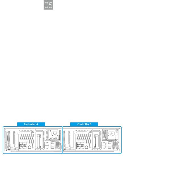
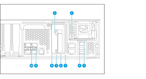
Rear Panel
Product Overview 13

ES2486dc User Guide
No. |
|
Component |
No. |
|
Component |
1 |
PCIe low-profile covers |
8 |
Ethernet Port 2 (GbE RJ45) |
||
|
|
|
|
||
2 |
Battery backup unit |
9 |
Power button |
||
|
|
|
|
||
3 |
Power supply unit |
10 |
Service port |
||
|
|
|
|
|
Note |
|
|
|
|
|
|
|
|
|
|
|
This port is only for engineering |
|
|
|
|
|
purposes. |
|
|
|
|
||
4 |
Reset button |
11 |
Ethernet port 4 (10GbE SFP+) |
||
|
|
|
|
||
5 |
USB 3.0 Type-A ports |
12 |
Ethernet port 5 (10GbE SFP+) |
||
|
|
Note |
|
|
|
|
|
|
|
|
|
|
|
This port is only for engineering |
|
|
|
|
|
purposes. |
|
|
|
|
|
|
|
||
6 |
Ethernet port 1 (GbE RJ45, management |
13 |
Ethernet port 7 (10GbE SFP+) |
||
|
port) |
|
|
|
|
7 |
Ethernet port 3 (GbE RJ45) |
14 |
Ethernet port 6 (10GbE SFP+) |
||
|
|
|
|
|
|
Product Overview 14
ES2486dc User Guide
Rear Panel LEDs
No. |
Component |
No. |
|
Component |
1 |
Battery backup unit LED |
6 |
Battery backup unit status LED |
|
|
|
|
|
|
2 |
Power supply LED |
7 |
Fan status LED |
|
|
|
|
|
|
3 |
Gigabit Ethernet activity LED |
8 |
Status LED |
|
|
|
|
|
|
4 |
Gigabitt Ethernet speed LED |
9 |
10 |
Gigabit Ethernet activity LED |
|
|
|
|
|
5 |
High availability LED |
10 |
10 |
Gigabit Ethernet speed LED |
|
|
|
|
|
The following LED information applies only when the drive is correctly installed and when the NAS is connected to the network.
LED |
Status |
|
Description |
Power supply unit |
Green |
• |
The NAS is powered on. |
|
|
• |
The NAS power supply is functioning normally. |
|
|
|
|
|
Flashing green |
The NAS is powering off. |
|
|
|
|
|
|
Orange |
The AC power cord has been disconnected or is |
|
|
|
malfunctioning. |
|
|
|
|
|
|
Off |
One or more of the following conditions occurred: |
|
|
|
• |
The AC power is unavailable. |
|
|
• |
The power supply has failed. |
|
|
|
|
Battery backup unit |
Green |
The battery backup unit is functioning normally. |
|
|
|
|
|
|
Red |
A battery backup unit malfunction occurred. |
|
|
|
|
|
|
Orange |
The battery backup unit is charging. |
|
|
|
|
|
|
Off |
The battery backup unit is not correctly attached to the |
|
|
|
ES2486dc. |
|
|
|
|
|
Product Overview 15
ES2486dc User Guide
LED |
Status |
|
Description |
|
Status |
Green |
The system is operating normally. |
||
|
|
|
||
|
Flashing green |
The system is booting. |
||
|
|
|
||
|
Off |
The system is powered off. |
||
|
|
|
||
Fan |
Green |
The fan is functioning normally. |
||
|
|
|
||
|
Orange |
A fan malfunction occurred. |
||
|
|
|
||
|
Off |
The fans are not detected. |
||
|
|
|
||
Battery backup unit |
Green |
The battery backup unit status is functioning normally. |
||
status |
|
|
|
|
Orange |
A write buffer for Copy-to-Flash occurred. |
|||
|
||||
|
|
For details, see Battery Backup Unit. |
||
|
|
|
||
|
Off |
One or more of the following conditions occurred: |
||
|
|
• |
The storage controller is powered off. |
|
|
|
• |
The system cannot detect the battery backup unit. |
|
|
|
|
||
High availability |
Green |
High availability is currently active. |
||
|
|
|
||
|
Flashing orange |
One of the following situations occurred: |
||
|
|
• |
Performing takeover: The dual active-active |
|
|
|
|
controller system enables a controller to take over |
|
|
|
|
the pool disk resources and access the data upon |
|
|
|
|
the failure of the other controller. Takeovers can be |
|
|
|
|
initiated manually or set up with the automatic |
|
|
|
|
system failover protection. For more details, see the |
|
|
|
|
QES User Guide. |
|
|
|
• |
Undergoing giveback: One of the storage |
|
|
|
|
controllers has taken over the system. The other |
|
|
|
|
storage controller has resumed operations and is |
|
|
|
|
ready to resume data service. Giveback can be |
|
|
|
|
initiated manually or set up with automatic failback |
|
|
|
|
after system recovers. For more details, see the |
|
|
|
|
QES User Guide. |
|
|
|
|
||
|
Orange |
The storage controller has taken over the other storage |
||
|
|
controller. |
||
|
Off |
One or more of the following conditions has occurred: |
||
|
|
• |
The storage controller has failed. |
|
|
|
• |
The storage controller is powered off. |
|
|
|
|
||
10 Gigabit Ethernet |
Green |
The network connection is operating at 10GbE. |
||
port speed |
|
|
|
|
Orange |
The network connection is operating at 1GbE |
|||
|
||||
|
|
|
||
|
Off |
The network connection is operating at 100 Mbps. |
||
|
|
|
||
10 Gigabit Ethernet |
Green |
The network link is active. |
||
port activity |
|
|
|
|
Flashing green |
The network link is active. |
|||
|
||||
|
|
|
||
|
Off |
There is no network link. |
||
|
|
|
||
1 Gigabit Ethernet |
Green |
The network link has been established. |
||
port activity |
|
|
|
|
Flashing green |
The network link is active. |
|||
|
||||
|
|
|
||
|
Off |
There is no network link. |
||
|
|
|
|
|
Product Overview 16

ES2486dc User Guide
LED |
Status |
Description |
|
1 Gigabit Ethernet |
Green |
The network connection is operating at 1GbE. |
|
port speed |
|
|
|
Orange |
The network connection is operating at 100 Mbps. |
||
|
|||
|
|
|
Storage Controller Power Button
Operation |
User Action |
|
Result |
Power on |
Press the button once. |
The storage controller powers on. |
|
|
|
|
|
Power off |
Press and hold the button for 5 |
The storage controller powers off. |
|
|
seconds. |
|
|
Force power off |
Press and hold the button for 10 |
The storage controller shuts down. |
|
|
seconds. |
|
Warning |
|
|
|
|
|
|
|
Use this method only |
|
|
|
when the storage |
|
|
|
controller is |
|
|
|
unresponsive. This action |
|
|
|
may result in data loss. |
|
|
|
|
Reset Button
Operation |
User Action |
|
|
Result |
Basic system reset |
Press and hold the button for 3 |
The following settings are set to |
||
|
seconds. |
default values. |
||
|
|
• |
System administrator |
|
|
|
|
password: admin |
|
|
|
• |
TCP/IP configuration: |
|
|
|
|
• |
IP address settings: |
|
|
|
|
Automatically obtained via |
|
|
|
|
DHCP |
|
|
|
• |
Jumbo frames: Disabled |
|
|
|
• |
Port trunking mode: |
|
|
|
|
Failover (multi-LAN |
|
|
|
|
models only) |
|
|
• |
Security level: Low (Allow all |
|
|
|
|
connections) |
|
|
|
• |
LCD panel password: (blank) |
|
|
|
• |
VLAN: Disabled |
|
|
|
• |
Service binding: NAS services |
|
|
|
|
can run on any available |
|
|
|
|
network interface |
|
Product Overview 17
ES2486dc User Guide
Operation |
User Action |
Result |
Advanced system reset |
Press and hold the button for 10 |
The device performs a basic |
|
seconds. |
system reset. All default system |
|
|
settings are also restored, deleting |
|
|
all previously created users, user |
|
|
groups, and shared folders. The |
|
|
user data stored on the disks is |
|
|
retained. |
|
|
To retrieve data after an advanced |
|
|
system reset, recreate the |
|
|
previous folder structure on the |
|
|
NAS. |
|
|
|
Battery Backup Unit
The battery backup unit (BBU) protects the data integrity of each storage controller. If both power supply units fail during a power outage, the system uses the BBUs for power and activates the asynchronous DRAM refresh (ADR) feature of the processors. While the BBUs supply power, cached data stored in the DRAM are written to the M.2 SSDs. This process is called Copy-to-Flash. Once power is restored and the system restarts, any logs, archives, or other important data are reconstructed from the data stored on the M. 2 SSDs.
Warning
During a power outage, do not remove storage controllers while their BBU status LEDs are orange. Removing a storage controller during this period interrupts the Copy-to-Flash process and may result in data loss.
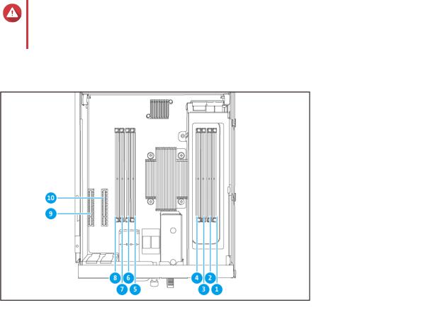
System Board
No. |
|
Component |
No. |
Component |
1 |
Memory slot 1 |
|
6 |
Memory slot 6 |
|
|
|
|
|
2 |
Memory slot 2 |
|
7 |
Memory slot 7 |
|
|
|
|
|
3 |
Memory slot 3 |
|
8 |
Memory slot 8 |
|
|
|
|
|
Product Overview 18
Loading...