

Page 1
RLX-OPC-SRV
ProSoft Software
RadioLinx® OPC Server for Frequency
Hopping and Industrial Hotspot™ Radios
January 22, 2009
USER MANUAL
Page 2

Please Read This Notice
The use and configuration of this software requires a reasonable working knowledge of the involved protocols and the
application in which they are to be used. For this reason, it is important that those responsible for implementation
satisfy themselves that the combination will meet the needs of the application without exposi ng personnel or
equipment to unsafe or inappropriate working conditions.
This manual is provided to assist the user. Every attempt has been made to assure that the information provided is
accurate and a true reflection of the product's functionality. In order to assure a complete understanding of the
operation of the product, the user should read all applicable ProSoft documentation on the operation of the module
and protocol driver.
Under no conditions will ProSoft Technology, Inc. be responsible or liable for indirect or consequentia l damages
resulting from the use or application of the product. Reproduction of the contents of this manual, in whole or in part,
without written permission from ProSoft Technology, Inc. is prohibited.
Information in this manual is subject to change without notice and does not represent a commitment on the part of
ProSoft Technology, Inc. Improvements and/or changes in this manual or the product may be made at any time.
These changes will be made periodically to correct technical inaccuracies or typographical errors.
Your Feedback Please
We always want you to feel that you made the right decision to use our products. If you have suggestions, comments,
compliments or complaints about the product, documentation or support, please write or call us.
ProSoft Technology
1675 Chester Avenue, Fourth Floor
Bakersfield, CA 93301
+1 (661) 716-5100
+1 (661) 716-5101 (Fax)
http://www.prosoft-technology.com
Copyright © ProSoft Technology, Inc. 2009. All Rights Reserved.
RLX-OPC-SRV User Manual
January 22, 2009
ProSoft Technology ®, ProLinx ®, inRAx ®, ProTalk® and RadioLinx ® are Registered Trademarks of ProSoft
Technology, Inc.
Page 3

Contents RLX-OPC-SRV ♦ ProSoft Software
RadioLinx® OPC Server for Frequency Hopping and Industrial Hotspot™ Radios
Contents
Please Read This Notice 2
Your Feedback Please........................................................................................................................2
1 Start Here 5
1.1 About the RadioLinx OPC Server .............................................................................5
1.2 Tags That Can Be Read............................................................................................6
1.3 System Requirements.............................................................................................15
1.4 Set Up Network.......................................................................................................15
2 Installing the Server 17
2.1 Choosing the Right RadioLinx OPC Server Project for Your Application...............17
2.2 Installation Process.................................................................................................18
3 Configuring the Server 19
3.1 Opening the Configuration Tool..............................................................................19
3.2 Creating a Configuration .........................................................................................21
3.3 Loading Your Configuration ....................................................................................25
3.4 Validating Your Configuration .................................................................................26
3.5 Adding a Channel....................................................................................................27
3.6 Channel Settings.....................................................................................................28
3.7 Adding a Radio........................................................................................................30
3.8 Radio Settings.........................................................................................................31
3.9 Adding Tags............................................................................................................31
3.10 Changing the Server's Update Rate........................................................................32
3.11 Adjusting an Existing Radio or Channel..................................................................32
3.12 OPC Reset Tags / Commands................................................................................32
3.13 Description of OPC "Commands" ...........................................................................33
4 Security and Password Protection 35
4.1 Password Protection for the Server ........................................................................35
5 DCOM Configuration 37
5.1 DCOM Configuration...............................................................................................37
5.2 My Computer Properties Checks............................................................................38
5.3 Component Services...............................................................................................44
5.4 RadioLinx OPC Server Properties ..........................................................................50
6 Connect to Server and Monitor Tags 57
6.1 Matrikon Example....................................................................................................57
6.2 RSView Example.....................................................................................................65
6.3 WonderWare Example............................................................................................86
ProSoft Technology, Inc. Page 3 of 108
January 22, 2009
Page 4

Contents RLX-OPC-SRV ♦ ProSoft Software
RadioLinx® OPC Server for Frequency Hopping and Industrial Hotspot™ Radios
7
Support, Service & Warranty 99
7.1 How to Contact Us: Technical Support................................................................... 99
7.2 Return Material Authorization (RMA) Policies and Conditions............................. 100
7.3 LIMITED WARRANTY.......................................................................................... 101
Index 107
Page 4 of 108 ProSoft Technology, Inc.
January 22, 2009
Page 5
Start Here RLX-OPC-SRV ♦ ProSoft Software RadioLinx® OPC Server for Frequency Hopping and Industrial Hotspot™ Radios
1 Start Here
In This Chapter
About the RadioLinx OPC Server............................................................5
Tags That Can Be Read..........................................................................6
System Requirements...........................................................................15
Set Up Network.....................................................................................15
For most applications, the following installation and configuration steps will work
without additional programming. ProSoft Technology strongly recommends that
you complete the steps in this chapter before developing a custom application.
This manual will walk you through the following tasks.
1 Setting up your network (page 15)
2 Install the server (page 17)
3 Configuring the server (page 19)
4 Security issues (page 35)
5 Setting up OPC client to monitor radios (page 57)
1.1 About the RadioLinx OPC Server
OPC is OLE for Process Control. OPC is open connectivity in industrial
automation and the enterprise systems that support industry.
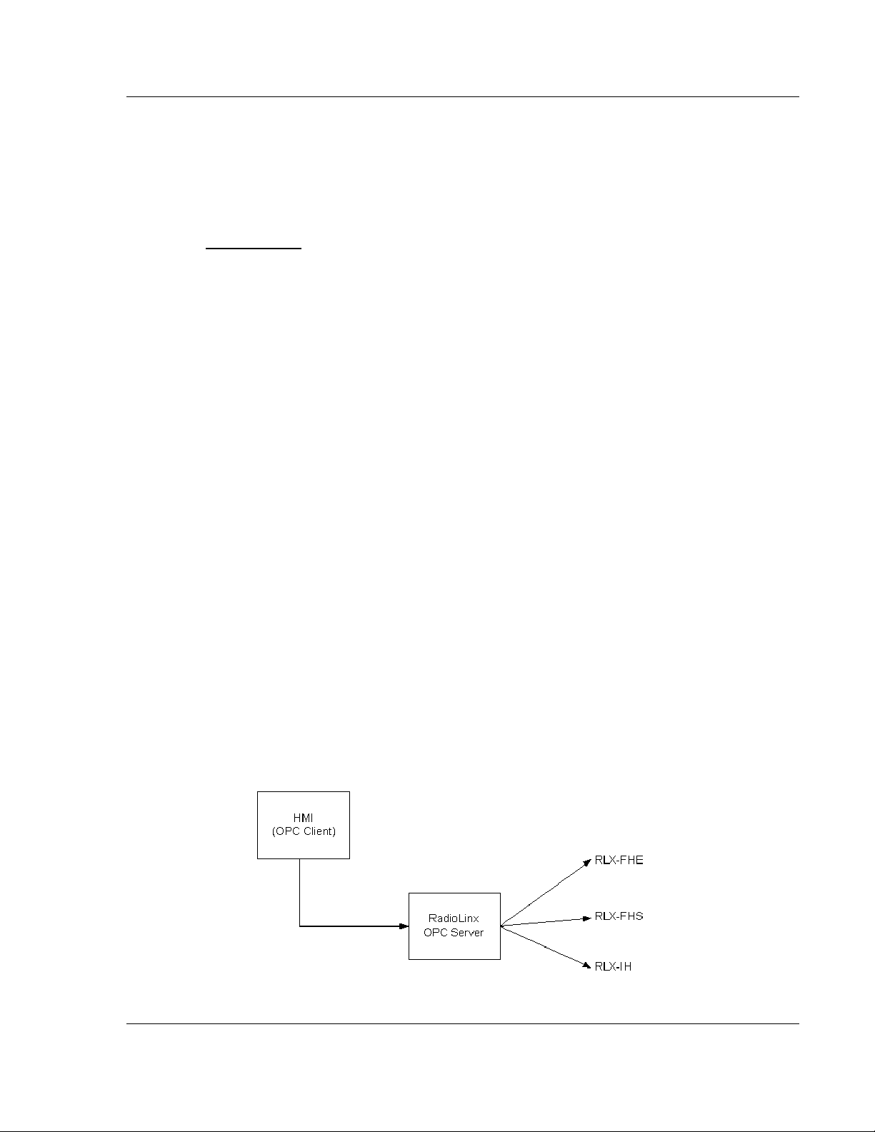
The purpose of the RadioLinx OPC Server is to seamlessly link customer
applications to RadioLinx radios.
It will allow any application that can act as an OPC Client, such as an HMI, to
interact with most RadioLinx radios to get signal strength, serial number, limited
throughput information as well as other useful statistics.
ProSoft Technology, Inc. Page 5 of 108
January 22, 2009
Page 6
RLX-OPC-SRV ♦ ProSoft Software Start Here
RadioLinx® OPC Server for Frequency Hopping and Industrial Hotspot™ Radios
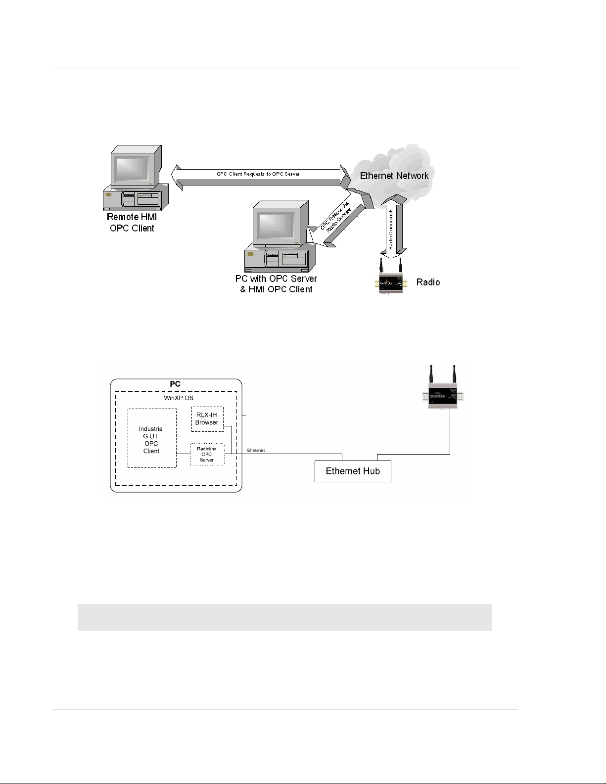
The RadioLinx OPC Server operates in the background on any PC. It
independently manages all requests from OPC Clients for information on
RadioLinx radios. The clients can be programs running either on the same PC as
the OPC Server or on a separate PC connected via a network connection.
1.2 Tags That Can Be Read
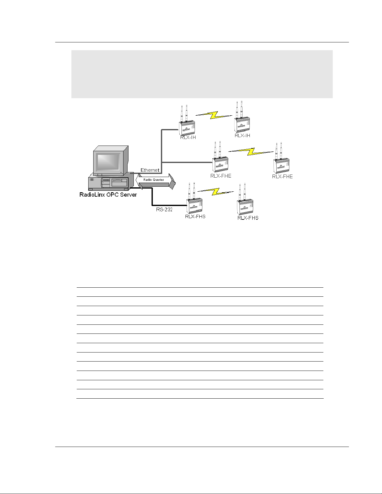
The RadioLinx OPC Server manages querying the RadioLinx radios over the
appropriate connections. It is configured by the user to query RLX-FH and RLXIH radios over the appropriate Ethernet port on the PC running the RLX OPC
Server. The user defines a "connection" within the RLX OPC Server for a
particular Ethernet port. They then simply associate as many RLX-FH and IH
Ethernet radios with that port. The OPC Server then knows to direct any queries
of those radios over that connection.
Note: For RLX-FHS radios, the connection will be done through the serial port.
The RadioLinx OPC Server is software provided by ProSoft Technology to assist
in using RadioLinx products. The following sections we will guide you in
installation of prerequisites, RLX OPC Server software, RLX OPC Configuration
Tool, setting up the network, installing Server, configuring Server and connecting
to Server, and how to monitor tags.
Page 6 of 108 ProSoft Technology, Inc.
January 22, 2009
Page 7
Start Here RLX-OPC-SRV ♦ ProSoft Software
RadioLinx® OPC Server for Frequency Hopping and Industrial Hotspot™ Radios
Notes: Only one process can communicate to a radio at the same time. Attempting to
communicate with more than one process at a time can cause unpredictable results.
In order to prevent multiple processes from communicating to a radio at the same time, switch the
RadioLinx OPC Server into pause mode while running ControlScape.
In addition, the validation option on the server will be disabled when the server is running.
1.2.1 RadioLinx Industrial Hotspot Radios
RLX-IH
RLX-IHW
RLX-IHW-66
RLXIB-IHW
RLXIB-IESC
Tag Name Contracted name Data Type
RSSI RSSI Integer
Firmware Version FirmVersion String
SSID SSID String
MAC ID MACID String
Up Time UpTime Unsigned Integer
Parent MAC ParentMAC String
Number of Associations Associations Integers
Total Bytes TX TotBytTX Integer
Soft Reset* SoftReset Integer
Total Good Packs TX TotGoodPacksTX Integer
Total Failed Packs TX TotFailPacksTX Integer
* Are also write tags. TX = Transmitted
ProSoft Technology, Inc. Page 7 of 108
January 22, 2009
Page 8

RLX-OPC-SRV ♦ ProSoft Software Start Here
RadioLinx® OPC Server for Frequency Hopping and Industrial Hotspot™ Radios
1.2.2 RadioLinx Frequency Hopping Radios
RLX-FHS
RLX-FHE
RLX-FHES
Tag Name Contracted name Data Type
RSSI RSSI Integer
Signal-to-Noise Ration SignalToNoise Integer
Associations Associations Integer
Bit error Rate BitErrRate Floating Point
Reset Statistics* Reset_stats Integer
Serial Number SerialNum String
Parent Address ParentAdd Integer
Total Bytes Forward TotBytFwd Integer
Total Bytes Reverse TotBytRev Integer
TX Packet Errors TxPackErrs Integer
Total Good Packets TotGoodPacks Integer
* Are also write tags. TX = Transmitted
1.2.3 RLX-IFHE
Tag Name Description
RSSI Receive Signal Strength Indicator measurement.
Unit Description Radio name
IP Address The IP Address of the current radio.
Unit Address:
Retransmissions
Destination Address This register specifies the ultimate destination for the data.
Roaming
Serial Number Serial number of radio (RF) module.
Version Firmware version within radio module.
The unit address is, and must be, a unique identifier of each modem in
a network.
VALUES
1 Master
65535 Broadcast
This register determines the maximum amount of times that a packet
will be retransmitted (in addition to the initial transmission).
VALUES
0-255
VALUES
1-65535
This feature allows a Remote unit to synchronize with a specified
‘upstream’ unit (either Master or Repeater).
VALUES:
65535 full roaming
1-254
specific (fixed) unit address (Master or Repeater)
with which to associate
Page 8 of 108 ProSoft Technology, Inc.
January 22, 2009
Page 9

Start Here RLX-OPC-SRV ♦ ProSoft Software
RadioLinx® OPC Server for Frequency Hopping and Industrial Hotspot™ Radios
Tag Name Description
Temperature Temperature as measured within the radio module.
Voltage Supply voltage as measured on motherboard.
VSWR
SoftwareVersion Core radio firmware version (.mhx file)
Operation Mode: The selected mode of operation: Master, Repeater, or Remote.
Link Rate:
RF Output Power:
Network Type:
Channel Mode
Voltage Standing Wave Ratio. Ideally 1:1 (or 1.00), this value gives an
indication of how much power is being reflected back to the radio from
the antenna relative to how much is being transmitted.
This is the RF communications Link Rate. A lower link rate offers better
receive sensitivity performance; a higher link rate, better throughput. All
IFHx radios in a network must use the same Link Rate.
This setting establishes the transmit power level which will be presented
to the antenna connector at the rear of a IFHx network. Unless required,
the RF Output Power should be set not for maximum, but rather for the
minimum value required to maintain. FCC regulations allow for up to
36dBi effective isotropic radiated power (EIRP). The sum (in dBm) of
the transmitted power, the cabling loss, and the antenna gain cannot
exceed 36dBi.
Type of RADIO network: Point-to-MultiPoint network (PMP), Point-ToPoint network (PTP), Peer-to-Peer (P2P), or Everyone-to-Everyone
(E2E)
VALUES:
Point-to-Multipoint
Point-to-Point
Peer-to-Peer
Everyone-to-Everyone
PMP with ACK
This option applies only to COM 1. Determines which serial interface
shall be used to connect to external devices: RS232, RS485, or RS422.
When an interface other than RS232 is selected, the DE9 port will be
inactive.
VALUES
RS232
RS485
RS422
Data Baud Rate
The serial baud rate is the rate at which the modem is to communicate
with the attached local asynchronous device.
NOTE: Most PCs do not readily support serial communications
greater than 115200bps.
VALUES: bits per second (bps)
Data Format
230400, 115200, 57600, 38400, 28800, 19200, 14400,
and 921600 may be selected for RS422 or RS485 Channel Modes.
This setting determines the format of the data on the serial port. The
default is 8 data bits, No parity, and 1 Stop bit.
9600, 460800
VALUES:
8N1, 8N2, 8E1, 8O1, 7N1, 7N2, 7E1, 7O1, 7E2, 7O2
ProSoft Technology, Inc. Page 9 of 108
January 22, 2009
Page 10

RLX-OPC-SRV ♦ ProSoft Software Start Here
RadioLinx® OPC Server for Frequency Hopping and Industrial Hotspot™ Radios
Tag Name Description
Flow Control
Used to enhance the reliability of serial data communications,
particularly at higher baud rates.
VALUES
Hardware
None
CTS Framing
Ethernet Received
Bytes
Ethernet Received
Packets
Ethernet Received
Multi-Cast
Ethernet Transmitted
Bytes
Ethernet Transmitted
Packets
Ethernet Collisions
Radio Received Bytes Number of bytes received by the Radio (RF).
Radio Received
Packets
Radio Received Errors Number of errors received by the Radio (RF).
Radio Received
Dropped Packets
Radio Transmitted
Bytes
Radio Transmitted
Packets
Radio Transmitted
Errors
Radio Collisions
COM1 Received Bytes Number of bytes received by the Serial port.
COM1 Received
Packets
COM1 Transmitted
Bytes
COM1 Transmitted
Packets
Specifies the number of bytes received by the Ethernet port.
Specifies the number of packets received by the Ethernet port.
Specifies the number of multi-cast packets that are received by the
Ethernet port.
Specifies the number of bytes transmitted by the Ethernet port.
Specifies the number of packets transmitted by the Ethernet port.
The number of invalid packets caused from multiple devices
transmitting Ethernet data at the same time.
Number of packets received by the Radio (RF).
Number of received dropped packets recorded by the Radio (RF).
Number of bytes transmitted by the Radio (RF).
Number of packets transmitted by the Radio (RF).
Number of Radio(RF) transmission errors.
The number of invalid packets caused from multiple devices
transmitting RF data at the same time.
Number of packets received by the Serial port.
Number of bytes transmitted on the Serial port.
Number of packets transmitted on the Serial port.
If the attached device supports hardware
handshaking.
If the attached device does not support
hardware handshaking.
Uses the CTS signal to gate the output data on
the serial.
Page 10 of 108 ProSoft Technology, Inc.
January 22, 2009
Page 11

Start Here RLX-OPC-SRV ♦ ProSoft Software
RadioLinx® OPC Server for Frequency Hopping and Industrial Hotspot™ Radios
1.2.4 RLX-IFHS
Tag name Description
RSSI
Temperature Temperature as measured within the radio module.
Unit Address
Destination
Address
Retransmissions
Roaming
ProSoft Technology, Inc. Page 11 of 108
January 22, 2009
This register displays the average signal strength received over the
previous 4 hop intervals. Should the downstream unit(s) fail, a Master will
maintain the last RSSI reading display.
VALUES:
110 to –55dBm (maximum reading)
The unit address is, and must be, a unique identifier of each IFHS radio in a
network. The address value is 16-bits in length. The Master has by default,
and must retain, a unit address of 1; 65535 is the broadcast address.
VALUES
2-65534
As the name implies, this register specifies the ultimate destination for a
modem’s data.
Different network topologies dictate the configuration of Destination
Address:
PMP: Master Destination Address = 65535, Remote Destination Address
=1
PTP : Master Destination Address = UA of Remote, Remote Destination
Address =1
P2P : Master Destination Address =65535, Destination Address of each (of
2 / pair) Remote radio is the UA of the other
E2E : Destination Address of all radios=65535 (broadcast)
VALUES
1-65535
This register determines the maximum amount of times that a packet will be
retransmitted (in addition to the initial transmission), noting the following
specific behaviors in various network topologies:
PMP: Master will retransmit each data packet the exact number of times
specified; Slave will retransmit only if necessary, and then only until a given
packet is acknowledged or the value of the Slave’s retransmissions is
reached (after which it will discard the packet if retransmission not
successful).
PTP: Modem will retransmit to its counterpart only if necessary, and to a
maximum number of the value in retransmissions. Packet is discarded if
retransmissions are not successful. Recipients of packets will discard any
duplicates.
In a PMP system, set retransmissions to the minimum value required as,
effectively, the data throughput from Master to Remote is divided by 1 plus
the number stored in retransmissions.
VALUES
0-255
Roaming dictates which radio (by Unit Address (UA)) a Remote unit will
’look’ or ’attach to’ for its upstream signal path. This feature allows a
Remote unit to synchronize with a specified ‘upstream’ unit (either Master
or Repeater).
The options are as follows:
Roaming=65535:
With this value in its roaming register, a Remote will synchronize with an
Page 12

RLX-OPC-SRV ♦ ProSoft Software Start Here
RadioLinx® OPC Server for Frequency Hopping and Industrial Hotspot™ Radios
Tag name Description
upstream unit which has the same network address and static mask as the
Remote. Should that upstream unit fail, this Remote will attempt to
synchronize with another ’upstream’ unit within the same network. This
ability is particularly well-suited to mobile applications.
Roaming=1-254:
In most static (fixed) networks, where there are no Repeaters, the default
value of 1 is maintained: All Slaves synchronize to the Master (whose unit
address (UA) is 1). In networks where Repeaters are present, the value of
a Remote’s roaming value corresponds to the particular upstream radio,
with which a particular Remote is intended to communicate.
( e.g. A Slave with a UA=3 may have Roaming=2, where the radio with a
UA=2 is a Repeater between the Slave and the Master; the Repeater will
have Roaming=1.)
When setting up 3 radios for a Master-Repeater-Slave link, be sure to set
the Slave’s Roaming to the UA of the Repeater, and the Repeater’s
Roaming to the UA of the Master(1). This will ensure that data is routed
from the Slave through the Repeater to the Master; otherwise, if the Slave’s
Roaming is left at the default value of 1, the Slave will communicate directly
with the Master and bypassing the Repeater altogether.
VALUES:
65535 Full Roaming
1-254 Specific (fixed) UA of Master or Repeater with which to associate
Voltage Supply voltage as measured on motherboard.
VSWR
Operation Mode
Voltage Standing Wave Ratio. Ideally 1:1 (or 1.00), this value gives an
indication of how much power is being reflected back to the radio from the
antenna relative to how much is being transmitted.
The operating mode defines the role of a radio. An IHFS radio may be
configured for any role required within a radio network. This is convenient
for reasons of familiarity with any/all units, as well as for hardware sparing
purposes.
The default operating mode is dependent on which factory default option is
selected.
MASTER: Only one per network. In all network types data either originates
at, is destined to, or ‘passes through’ the Master.
REPEATER: May act simply as a ‘Repeater’ to store and forward data
to/from an upstream unit to/from a downstream unit (e.g. when there is a
long distance between the latter units), or, may act as a Repeater/Slave in
which case the above function is performed AND the unit may also
exchange data as a Slave within the network.
SLAVE: Interfaces with remote devices and communicates with Master
either directly or via Repeater(s). Communications between 2 or more
Slaves is possible - through the Master.
A ‘Remote’ (non-Master) modem is either a Repeater or a Slave. If a
Repeater is not being used as a Repeater/Slave (i.e. there is no device
attached to its local data port), leave its handshaking OFF (&K0) and set
the serial baud rate (S102) to 115200bps.
VALUES:
Master
Repeater
Slave
Page 12 of 108 ProSoft Technology, Inc.
January 22, 2009
Page 13

Start Here RLX-OPC-SRV ♦ ProSoft Software
RadioLinx® OPC Server for Frequency Hopping and Industrial Hotspot™ Radios
Tag name Description
Link Rate
RF Output Power
Network Type
This register determines the rate at which RF communications will occur
over a given network.
All radios within a particular network must be configured with the same
wireless link rate.
Faster link rates result in greater throughput, however, for each ’step’
increase in link rate, there is an approximately 1dB reduction in sensitivity.
VALUES
bits per second (bps)
19200
115200
172800
230400
270000
340000
This setting establishes the transmit power level which will be presented to
the antenna connector at the rear of the radio. Unless required Output
Power should be set not for maximum, but rather for the minimum value
required to maintain an adequate system fade margin.
FCC regulations allow for up to 36dBi effective isotropic radiated power
(EIRP). The sum (in dBm) of the transmitted power, the cabling loss, and
the antenna gain cannot exceed 36dBi.
VALUES
dBm (mW equivalent)
20 (100)
21 (125)
22 (160)
23 (200)
24 (250)
25 (320)
26 (400)
27 (500)
28 (630)
29 (800)
30 (1000)
Defines the type of network: point-to-multipoint, point-to-point, peer-to-peer,
or everyone-to-everyone
In a point-to-multipoint (PMP) network, the Master broadcasts data to all
units, and all remote units send their data (ultimately) to the Master.
A point-to-point (PTP) network involves a Master and a Slave (with 0 or
more Repeaters in-between).
Peer-to-Peer involves either communication between 2 (typically remote)
units (P2P) or between all units (everyone-to-everyone - E2E).
ALL modems in a network must have the SAME value for Network Type.
VALUES
Point-to-Multipoint
Point-to-Point
Peer-to-Peer or Everyone-to-Everyone
ProSoft Technology, Inc. Page 13 of 108
January 22, 2009
Page 14

RLX-OPC-SRV ♦ ProSoft Software Start Here
RadioLinx® OPC Server for Frequency Hopping and Industrial Hotspot™ Radios
Tag name Description
Channel Mode
Data Baud Rate
Data Format
Radio Received
Bytes
Radio rEceived
Packets
Radio Transmitted
Bytes
Radio Transmitted
Packets
Repeaters in
System
Defines the physical serial interface which will be used for data
communications.
VALUES
RS-232
half-duplex RS-485
full-duplex RS-485
The serial baud rate is the rate at which the modem is to communicate with
the attached local asynchronous device.
VALUES
bits per second (bps)
300, 600, 1200, 2400, 3600, 4800, 7200, 9600, 14400, 19200, 28800,
38400, 57600, 115200, 230400
This value determines the format of the data on the serial port. The default
is 8 data bits, No parity, and 1 Stop bit.
VALUES
8N1
8N2
8E1
8O1
7N1
7N2
7E1
7O1
7E2
7O2
Number of bytes received by the Radio(RF).
Number of packets received by the Radio(RF).
Number of bytes transmitted by the Radio(RF).
Number of packets transmitted by the Radio(RF).
This setting applies to the Master only. The default value is No, stating
there are no Repeaters in the network. If there are 1 or more Repeaters in
the network, configure this setting as Yes.
Page 14 of 108 ProSoft Technology, Inc.
January 22, 2009
Page 15

Start Here RLX-OPC-SRV ♦ ProSoft Software
RadioLinx® OPC Server for Frequency Hopping and Industrial Hotspot™ Radios
1.3 System Requirements
The following system requirements are the recommended minimum
specifications to successfully install and run RadioLinx OPC Driver.
Microsoft Windows compatible PC
Windows XP Professional with Service Pack 2 or higher, Windows VISTA, or
Windows 2003
Microsoft .NET Framework version 3.0 or higher
300 mHz Pentium processor (or equivalent)
128 megabytes of RAM
300 megabytes of available disk space
1.4 Set Up Network
See the ProSoft Technology documentation on your radio.
ProSoft Technology, Inc. Page 15 of 108
January 22, 2009
Page 16

RLX-OPC-SRV ♦ ProSoft Software Start Here
RadioLinx® OPC Server for Frequency Hopping and Industrial Hotspot™ Radios
Page 16 of 108 ProSoft Technology, Inc.
January 22, 2009
Page 17
Installing the Server RLX-OPC-SRV ♦ ProSoft Software RadioLinx® OPC Server for Frequency Hopping and Industrial Hotspot™ Radios
2 Installing the Server
In This Chapter
Choosing the Right RadioLinx OPC Server Project for Your Application17
Installation Process ...............................................................................18
2.1 Choosing the Right RadioLinx OPC Server Project for Your
Application
1 Go to www.prosoft-technology.com, or use the ProSoft Technology supplied
CD to retrieve RLX OPC software!
2 Open setup file and follow the install directions. The install process will copy
the RLX OPC Server and OPC Configuration Tool onto your PC.
Note: Before installing, verify that you have the Microsoft .NET Framework (version 3.0 or greater)
already installed. If you don’t then download this from Microsoft.com and continue installing
RadioLinx OPC Server. Select the ServerInstaller.msi file to install.
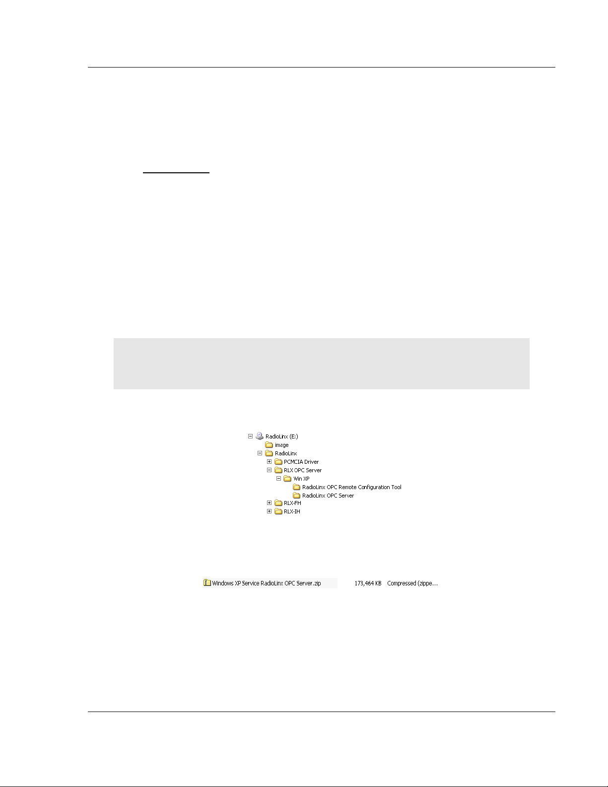
This is an example of the Tree structure you will see. See descriptions below and
select the version for your system.
The Window XP Service RadioLinx OPC Server is the recommended version.
Windows XP Service RadioLinx OPC Server
This is the primary server project. The configuration tool will also be installed.
ProSoft Technology, Inc. Page 17 of 108
January 22, 2009
Page 18

RLX-OPC-SRV ♦ ProSoft Software Installing the Server
RadioLinx® OPC Server for Frequency Hopping and Industrial Hotspot™ Radios
2.2 Installation Process
1 Launch the ServerInstaller.msi file to begin the installation process. You will
be asked for a directory to install to. Select a directory that Windows will have
access to for all user accounts and you would like to make the project
available to.
A registry entry will be placed in the Windows Run folder in order to load
some applications at Windows start up. These applications can only be
launched by a Windows session if the current user account has access to the
directory where the applications reside.
2 During the server installation process, you will be asked to install the OPC
Core Components 2.00 Redistributable.
Note: Unless you are 100% sure that you already have these "Core" components installed, it is
highly recommended that you complete this install as well.
3 When the installation is complete, you must restart your computer.
If you choose not to install the OPC Core Components and then later change
your mind, you can find the setup file for the core components in the "\Setup"
subdirectory of the main RadioLinx OPC Server folder.
Page 18 of 108 ProSoft Technology, Inc.
January 22, 2009
Page 19

Configuring the Server RLX-OPC-SRV ♦ ProSoft Software
RadioLinx® OPC Server for Frequency Hopping and Industrial Hotspot™ Radios
3 Configuring the Server
In This Chapter
Opening the Configuration Tool.............................................................19
Creating a Configuration........................................................................21
Loading Your Configuration...................................................................25
Validating Your Configuration................................................................26
Adding a Channel..................................................................................27
Channel Settings...................................................................................28
Adding a Radio ......................................................................................30
Radio Settings.......................................................................................31
Adding Tags..........................................................................................31
Changing the Server's Update Rate......................................................32
Adjusting an Existing Radio or Channel ................................................32
OPC Reset Tags / Commands..............................................................32
Description of OPC "Commands"..........................................................33
3.1 Opening the Configuration Tool
When you first install the server and configuration tool, the server will not be
configured to monitor your wireless radio network. The server is configured using
a separate utility. The first step in the configuration process is to open the server
and this utility.
Start OPC Monitor)
1 Click Start / Programs / RadioLinx OPC Server / RadioLinx OPC Monitor
-or-
2 Double-click on desktop icon for server
Start OPC Configuration Tool - to open as a Client
1 Click Start / Programs / RadioLinx OPC Server / RadioLinx OPC
Configuration Tool
-or-
Double-click on RadioLinx OPC Monitor system tray icon,
ProSoft Technology, Inc. Page 19 of 108
January 22, 2009
Page 20
RLX-OPC-SRV ♦ ProSoft Software Configuring the Server
RadioLinx® OPC Server for Frequency Hopping and Industrial Hotspot™ Radios
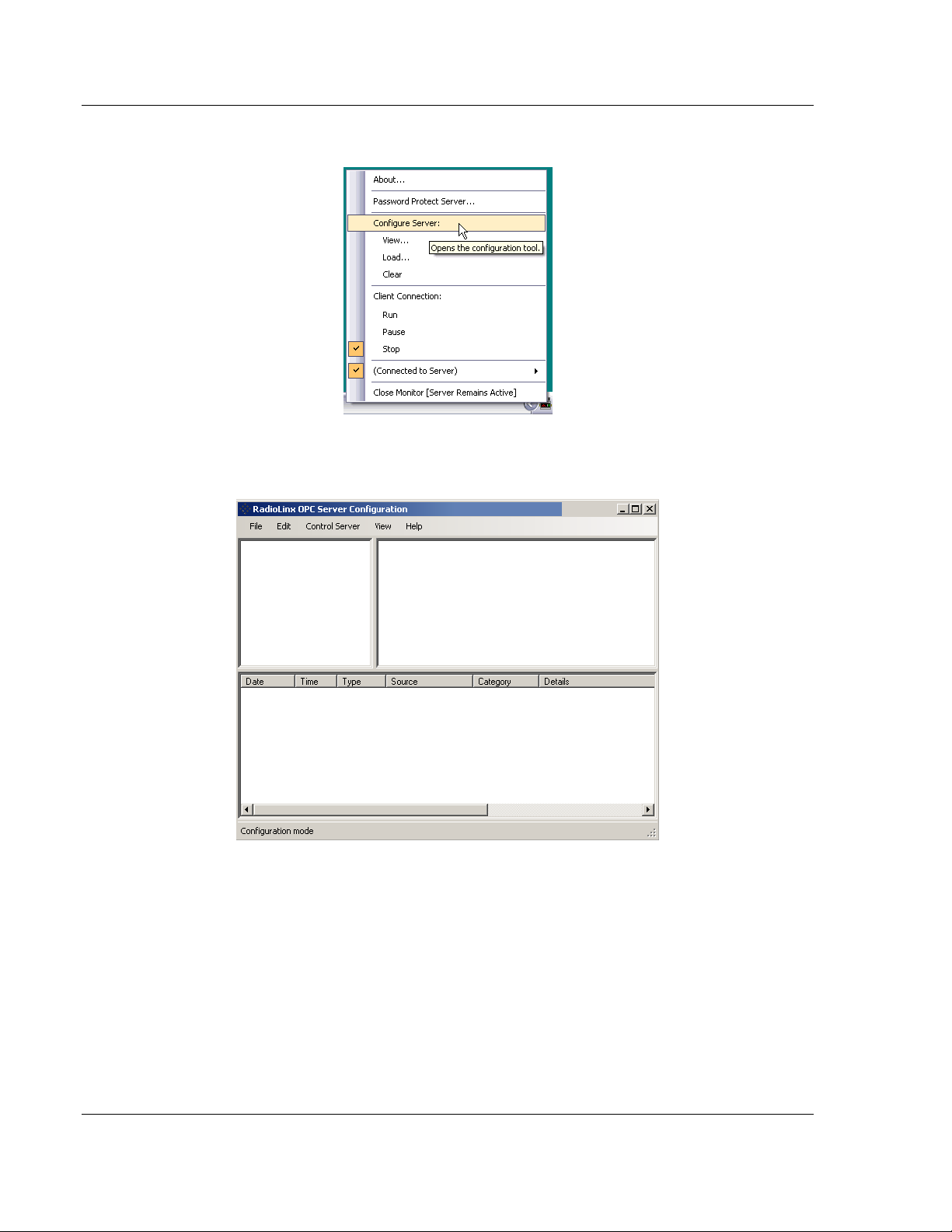
Or right click on icon, then select Configure Server.
One of the above processes brings up the RadioLinx OPC Server
Configuration screen shown below.
Page 20 of 108 ProSoft Technology, Inc.
January 22, 2009
Page 21
Configuring the Server RLX-OPC-SRV ♦ ProSoft Software
RadioLinx® OPC Server for Frequency Hopping and Industrial Hotspot™ Radios
3.2 Creating a Configuration
There are two methods for configuring the server. You can connect to the server
and then configure it directly, or you can save your configuration to disk and then
load it into the server manually.
3.2.1 Configure to Server Mode
When you use the Configure to Server mode, you will connect to a server
running on the same machine as the Configuration Tool. The Configure to Server
will save your work to the server.
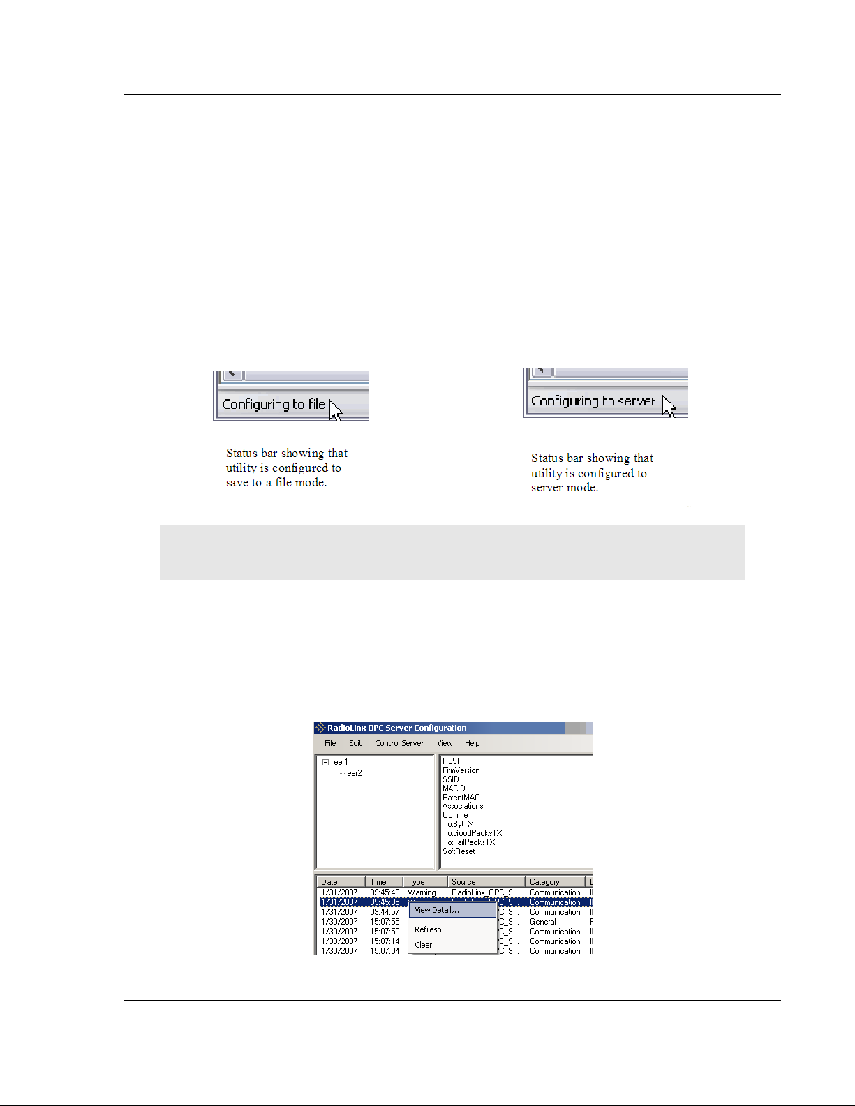
The status bar (bottom of box) should now say "Configuring to file." When you
connect to local or remote server it will change to "Configuring to server."
Note: If you have not created and saved a file for your radio, please follow the instructions in
Configure to File Mode for Adding a Channel (page 27), Radio (page 30) and Tags. (page 31)
Local Server Procedure
1 Click File / Configure to Server / Connect to Server / Local Server
The RadioLinx OPC Server Configuration box appears with Channel and
Radio (upper left panel), Tags (upper right) and Server Time Log on bottom.
If you right click on a date in Time Log, you can view details of that incident.
You can also configure a server that is running on another machine.
ProSoft Technology, Inc. Page 21 of 108
January 22, 2009
Page 22
RLX-OPC-SRV ♦ ProSoft Software Configuring the Server
RadioLinx® OPC Server for Frequency Hopping and Industrial Hotspot™ Radios
Remote Server Procedure
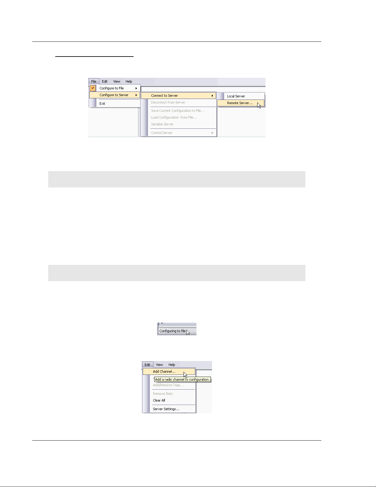
1 Click File / Configure to Server / Connect to Server / Remote Server
Enter the IP address or the name of the computer that the remote server is
running on.
You can choose to attempt a secure remote connection, or not.
Note: If the IP address is not valid, you will receive a "Connection Failed" message.
Secure connections require certain Windows security options to be in place
before they will work. The unsecured remote connection is a lot more reliable,
but it is possible for others to intercept and interpret the messages that are
sent.
2 Click OK button.
3.2.2 Configure to File Mode
This section details how to create a custom configuration for your server.
Note: Do not connect to a server using the Configuring to Server method.
If you are connected to the server, disconnect before proceeding.
1 Select File / Configure to Server / Disconnect from Server.
The status bar (bottom of screen) should now say "Configuring to file."
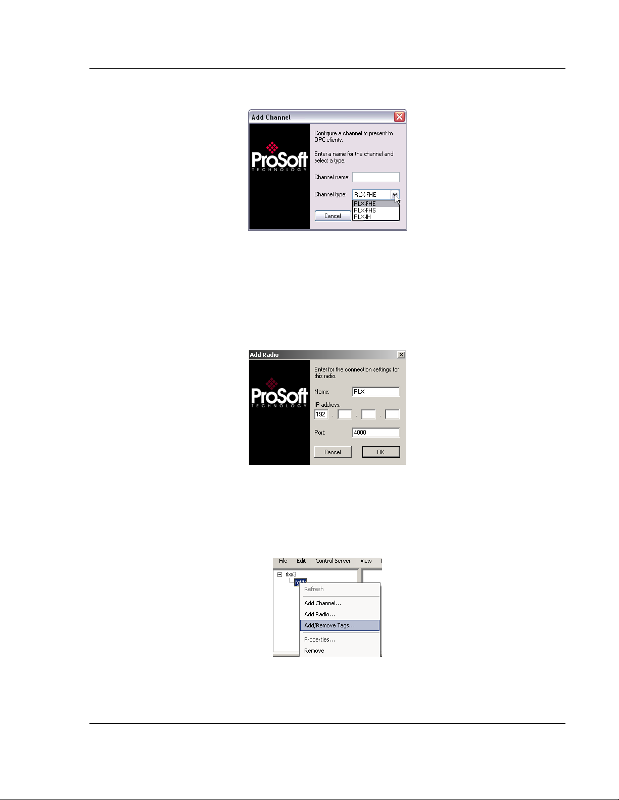
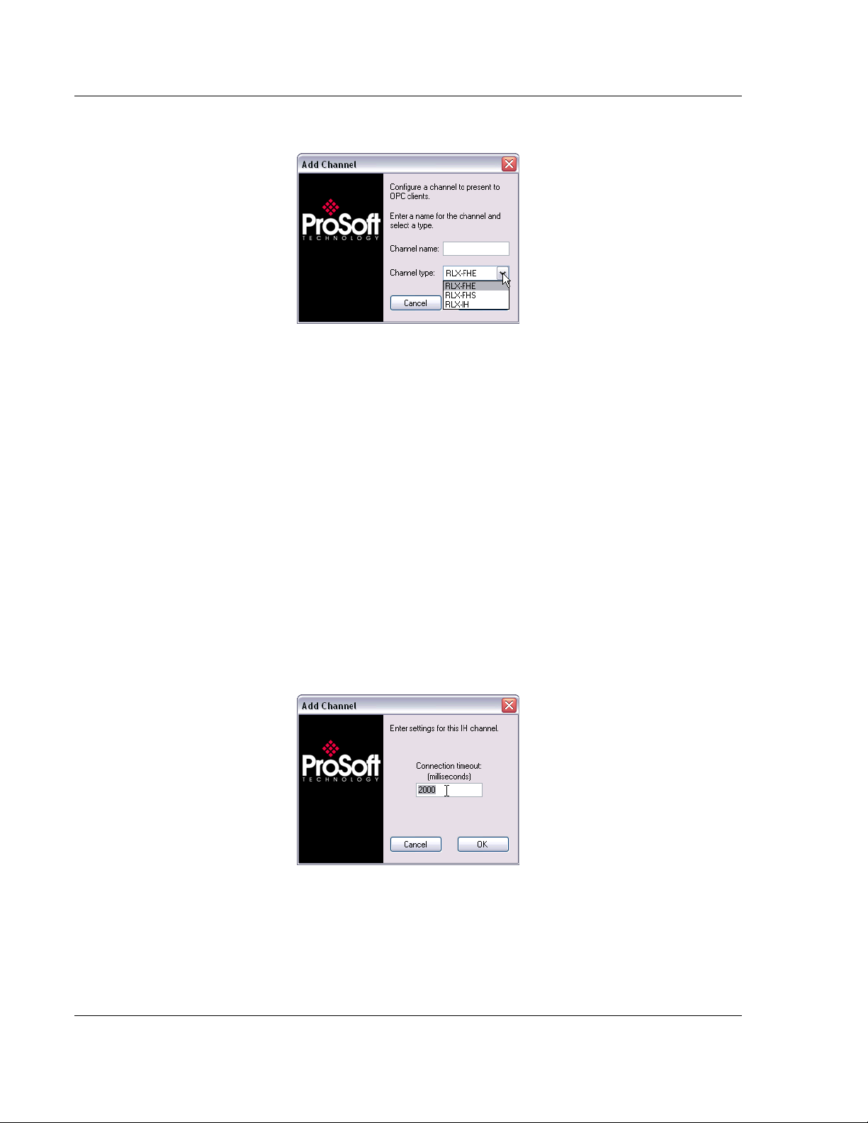
2 Add a Channel. Select Edit / Add Channel
3 Choose a Channel name and Channel type.
Page 22 of 108 ProSoft Technology, Inc.
January 22, 2009
Page 23
Configuring the Server RLX-OPC-SRV ♦ ProSoft Software
RadioLinx® OPC Server for Frequency Hopping and Industrial Hotspot™ Radios
4 Click Next. FHS is for serial connections.
5 A dialog box will appear for connection timeout. Default is 2000 milliseconds,
but you can decide your speed. Click OK.
6 Add a Radio. Select Edit / Add Radio.
- or -
7 Now that you have a Channel, you can right click on your Channel name and
select Add Radio. This will bring up the dialogue box below.
8 Choose a Name and give it your specific IP address. Click OK to accept.
9 Add or Remove Tags. Select Edit / Add/Remove Tags
- or -
10 You can right click on your Radio name and select Add/Remove Tags.
ProSoft Technology, Inc. Page 23 of 108
January 22, 2009
Page 24
RLX-OPC-SRV ♦ ProSoft Software Configuring the Server
RadioLinx® OPC Server for Frequency Hopping and Industrial Hotspot™ Radios
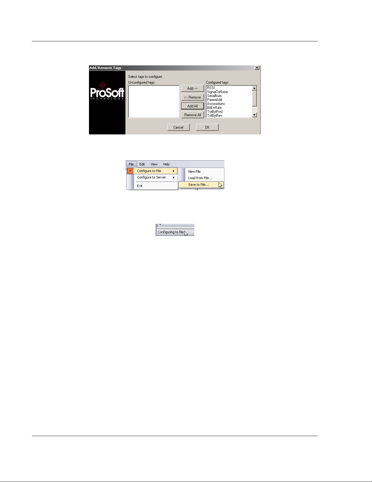
11 To Add or Remove tags, click on appropriate button. Then, click OK.
12 Click File / Configure to File / Save to File
13 Choose a directory and file name and click Save. The Status bar shows utility
in "Configuring to file".
If you want more detailed information on the procedures above please go to
Adding a channel, Adding a radio, Adding tags, and adjusting an existing
radio or channel in this manual.
Page 24 of 108 ProSoft Technology, Inc.
January 22, 2009
Page 25
Configuring the Server RLX-OPC-SRV ♦ ProSoft Software
RadioLinx® OPC Server for Frequency Hopping and Industrial Hotspot™ Radios
3.3 Loading Your Configuration
When you are finished creating and saving your configuration in the RLX OPC
Configuration Tool, you should Close it.
Note: If you saved your configuration to file, you will now need to load it into the RLX OPC Server.
If you chose the Configure to server method, none of the following steps are
necessary. Skip to "Validating Your Configuration."
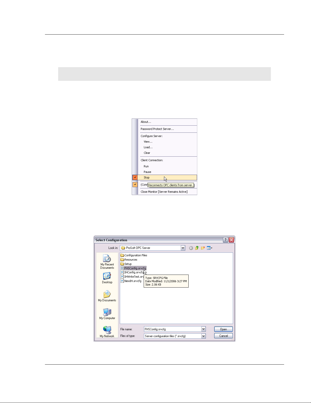
1 Right click on the RLX OPC Server system tray icon and make sure that the
server is stopped. If Stop is checked, the server is stopped.
2 If the server is running, select Stop to stop the server.
3 Right-click on the RLX OPC Server system tray icon and select Load
Configuration. The "Select Configuration" box opens.
4 Navigate to the directory where you saved your file and open it.
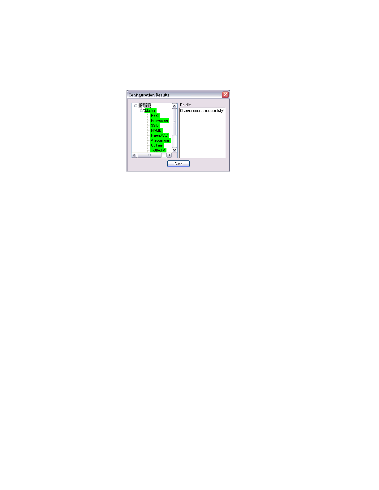
When the configuration is finished loading, the Configuration Results dialog will
appear.
ProSoft Technology, Inc. Page 25 of 108
January 22, 2009
Page 26
RLX-OPC-SRV ♦ ProSoft Software Configuring the Server
RadioLinx® OPC Server for Frequency Hopping and Industrial Hotspot™ Radios
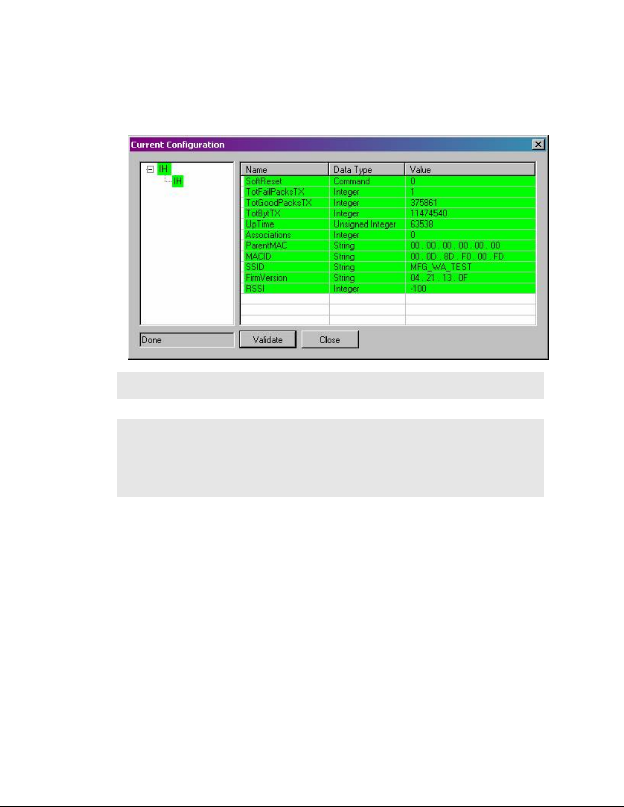
The Configuration Results dialog describes the configuration that was loaded into
the server. Items that are listed green were successfully configured. Red items
could not be configured. Select an item in order to see more details about why it
could not be loaded.
3.4 Validating Your Configuration
Before you attempt to connect to the server with your OPC client, you may want
to test your configuration and make sure everything is configured properly.
1 Right-click on the RLX OPC Server system tray icon and select View
Configuration.
The view pane on the left of the dialog shows you what channels and radios
are configured. The view pane on the right shows what tags are configured
for each radio.
2 Click Validate to test the configuration.
The server will attempt to communicate to your wireless radios. After a
pause, the items in the two view panes will turn green or red. Green items
were contacted successfully. Red items could not be contacted.
Page 26 of 108 ProSoft Technology, Inc.
January 22, 2009
Page 27
Configuring the Server RLX-OPC-SRV ♦ ProSoft Software
RadioLinx® OPC Server for Frequency Hopping and Industrial Hotspot™ Radios
Radios or channels that remain white have no tags associated with them. No
attempt is made to contact these items. Notice that the current values of the
tags are also displayed after validating.
Note: You can re-verify you are connected by pressing validate again. This will update the values.
3 Click Close when you are finished.
Notes: Only one process can communicate to a radio at the same time. Attempting to
communicate with more than one process at a time can cause unpredictable results.
In order to prevent multiple processes from communicating to a radio at the same time, switch the
RadioLinx OPC Server into pause mode while running ControlScape.
In addition, the validation option on the server will be disabled when the server is running.
3.5 Adding a Channel
Wireless radio networks are composed of RadioLinx radios of the same type
configured to communicate together. In the server, these networks are
represented by channels. A channel is a communications stream for
communicating to a specific type or model of radio.
The first step in configuring the server is to add a channel for your wireless
network.
1 Click Edit / Add Channel
-orRight click on top left pane and select Add Channel from the context menu.
ProSoft Technology, Inc. Page 27 of 108
January 22, 2009
Page 28
RLX-OPC-SRV ♦ ProSoft Software Configuring the Server
RadioLinx® OPC Server for Frequency Hopping and Industrial Hotspot™ Radios
A dialog opens.
2 Enter a custom name for the channel.
3 Select the RadioLinx product that the channel will communicate to from the
drop down list.
4 Click OK.
Another dialog opens.
5 Enter the settings specific to your radio network into this dialog.
(See also: Channel Settings)
6 Click OK.
A channel with the given name appears in the top left view pane.
3.6 Channel Settings
Connection Timeout: The time the server will wait for a response from the radio.
3.6.1 RLX-IH Channel
Page 28 of 108 ProSoft Technology, Inc.
January 22, 2009
Page 29
Configuring the Server RLX-OPC-SRV ♦ ProSoft Software
RadioLinx® OPC Server for Frequency Hopping and Industrial Hotspot™ Radios
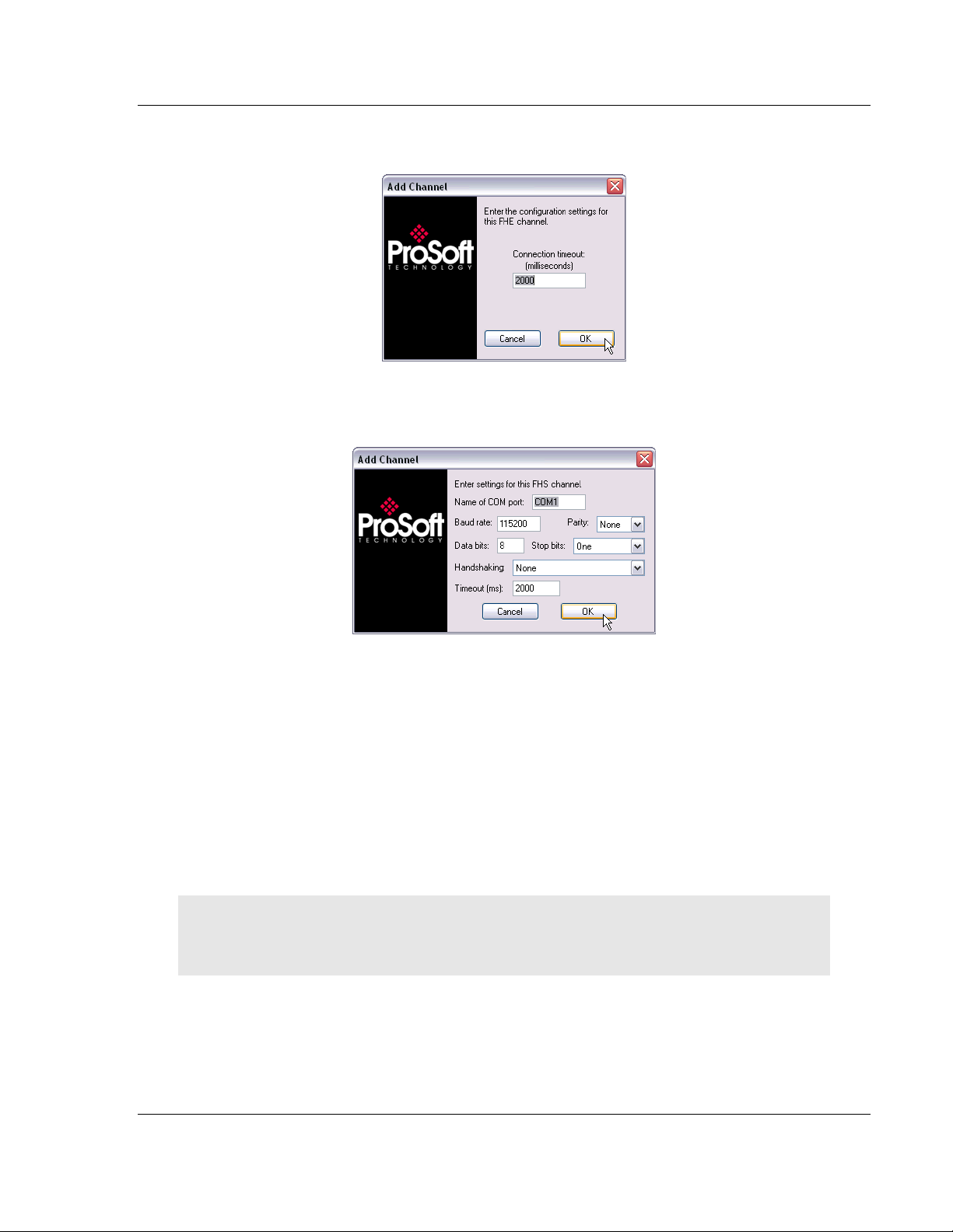
3.6.2 RLX-FHE Channel
3.6.3 RLX-FHS Channel
Name of COM port: The label of COM port that you are using to communicate to
the radio.
Baud rate: The baud rate of the COM port.
Parity: The parity settings for the COM port.
Data bits: The number of data bits used for communication via the COM port.
Stop bits: The number of stop bits used for communication via the COM port.
Handshaking: The flow control used by the COM port.
Timeout: The number of milliseconds that the server will wait for a response from
the radio.
Note: The settings can be copied from the properties window of the COM port that you are using to
connect to the radio network.
Note: The settings you enter for your FHS channel must be compatible with your com port.
ProSoft Technology, Inc. Page 29 of 108
January 22, 2009
Page 30
RLX-OPC-SRV ♦ ProSoft Software Configuring the Server
RadioLinx® OPC Server for Frequency Hopping and Industrial Hotspot™ Radios
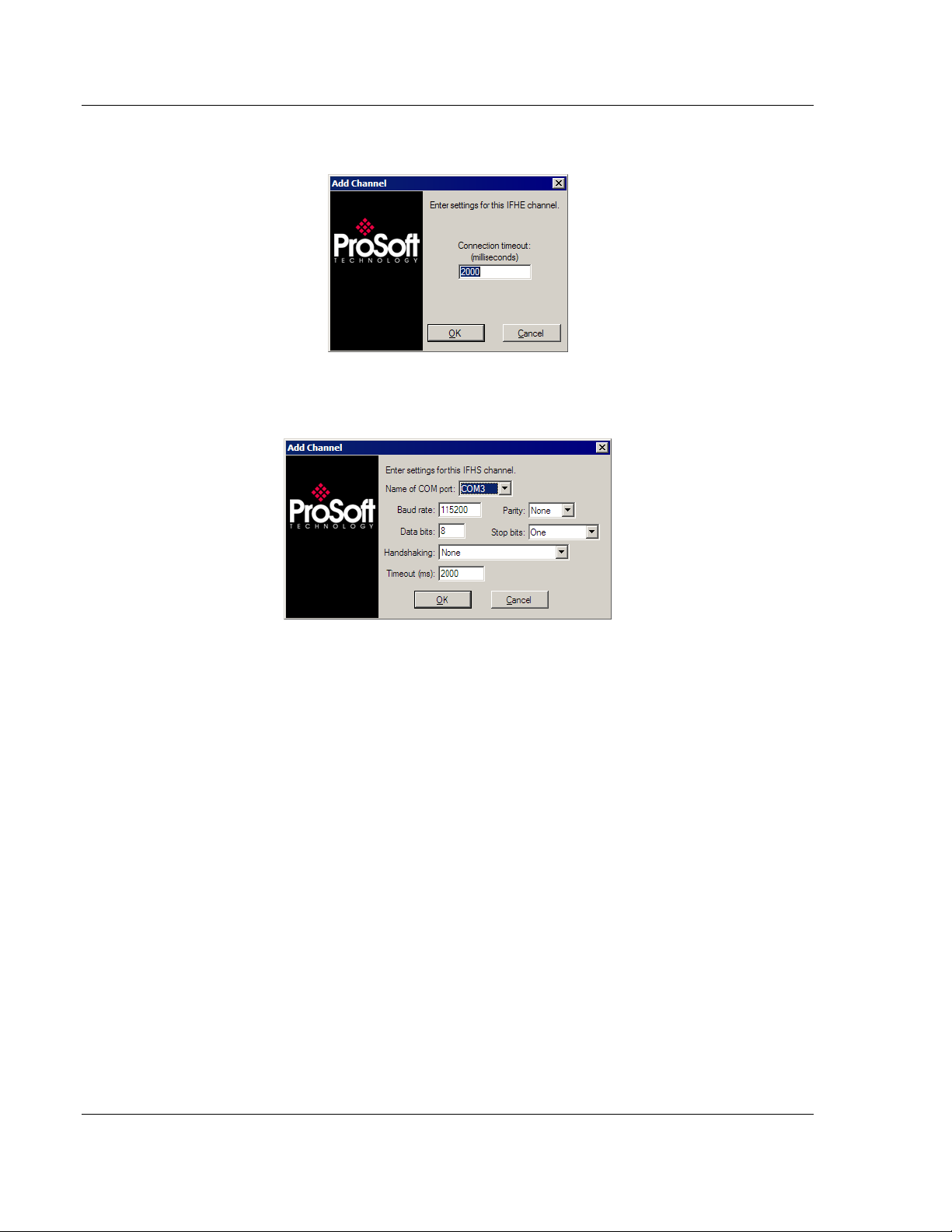
3.6.4 RLX-IFHE Channel
3.6.5 RLX-IFHS Channel
3.7 Adding a Radio
Purpose: Add radios that are part of your network to server configuration so that
OPC clients can monitor radio tags.
1 Select appropriate channel.
2 Click Edit / Add Radio.
-orRight click on appropriate channel / Add Radio…
"Add Radio" dialog opens.
3 Enter a custom name for the radio.
4 Enter settings for communicating to radio.
See Radio Settings for more details.
Page 30 of 108 ProSoft Technology, Inc.
January 22, 2009
Page 31

Configuring the Server RLX-OPC-SRV ♦ ProSoft Software
RadioLinx® OPC Server for Frequency Hopping and Industrial Hotspot™ Radios
3.8 Radio Settings
3.8.1 IH Radios
IP: The IP address of the IH radio to connect to. For more details, browse for
radios using the RadioLinx IH Browser.
Port: Defaults to 161. Only change if you have good reason for doing so.
Community: The SNMP community of this radio. Defaults to public. Enter a new
value if you have changed the SNMP community of any of your radios.
3.8.2 FHE Radios
IP: The IP address of the FHE radio to connect to. For more details, inspect your
ControlScape wireless network settings.
Port: Defaults to 4000. Only change if you have good reason for doing so.
3.8.3 FHS Radios
Radio address: The radio address of the radio to communicate to. For more
details, inspect your ControlScape wireless network settings.
3.8.4 IFHE Radios
IP: The IP address of the FHE radio to connect to. For more details, inspect your
ControlScape wireless network settings.
Port: Defaults to 4000. Only change if you have good reason for doing so.
3.8.5 IFHS Radios
Radio address: The radio address of the radio to communicate to. For more
details, inspect your ControlScape wireless network settings.
3.9 Adding Tags
Purpose: To select specific values to present to OPC clients.
1 Select radio.
2 Click Edit / Add/Remove Tags.
-orRight click on radio or top right pane and select Add/Remove Tags.
The Add/Remove Tags dialog opens.
3 Select the tags you wish to allow clients to monitor and click the ADD button.
4 Select the tags you no longer want clients to monitor and click Remove.
5 Click Add All or Remove All to add or remove all tags.
6 Click OK for tag changes to be accepted.
ProSoft Technology, Inc. Page 31 of 108
January 22, 2009
Page 32

RLX-OPC-SRV ♦ ProSoft Software Configuring the Server
RadioLinx® OPC Server for Frequency Hopping and Industrial Hotspot™ Radios
3.10 Changing the Server's Update Rate
Purpose: To change the update rate of the server.
1 Click Edit / Server settings…
2 Enter a new refresh rate.
3 Click OK.
Warning: It is not advisable to set the refresh rate lower than 3 to 5 seconds.
3.11 Adjusting an Existing Radio or Channel
3.11.1 Removing Items
1 Select item to remove.
2 Click Edit / Remove Item.
3 Confirm removal.
-orRight-click on item to remove and select Remove… from drop down menu.
4 Confirm removal.
-orClick File / Clear All to remove all items from the configuration.
3.11.2 Properties
Purpose: To change the settings or rename an existing item.
1 Select an item.
2 Click View / Properties.
3 The Properties dialog opens.
4 Make necessary changes.
Click OK.
-orRight-click on an item and select Properties.
3.12 OPC Reset Tags / Commands
The following OPC tags behave differently than the rest:
ResetStats
SoftReset
These OPC tags are referred to as commands. They are used for sending
messages to radios instead of monitoring values.
Commands have 3 possible values: -1, 0, 1.
The default value is 0.
-1 indicates that an error occurred when trying to send a message to a radio.
Page 32 of 108 ProSoft Technology, Inc.
January 22, 2009
Page 33

Configuring the Server RLX-OPC-SRV ♦ ProSoft Software
RadioLinx® OPC Server for Frequency Hopping and Industrial Hotspot™ Radios
0 indicates success when trying to send a message to a radio.
1 instructs the server to send the message to the radio.
The value of a command is solely driven by write requests from OPC clients. This
value will not be updated except in response to write requests.
To send a specific message to a radio, write a 1 to the respective OPC tag. The
server will forward the request to the radio and will then assign the OPC tag a
value of 0 or -1. 0 if the request was completed successfully, -1 if it failed.
You can set or clear the status of a command by writing a 0 or -1 value to it. The
server will only send the specified message to the radio when the command is
set to 1.
3.13 Description of OPC "Commands"
3.13.1 ResetStats (RLX-FH radios)
Clears the following radio values to zero:
TotBytFwd
TotBytRev
TotGoodPacks
TXPackErrs
3.13.2 SoftReset (RLX-IH radios)
SoftReset causes the RLX-IH radio to reboot. The radio will be temporarily
unavailable while rebooting. It is normal for other tags from this radio to change
to quality "OPC_QUALITY_LAST_KNOWN" while the radio is unavailable. After
5 to 30 seconds this situation should right itself automatically. Any attempt to
send a SoftReset command while the radio is rebooting will fail and SoftReset
will get a -1 value from the server.
Rebooting RLX-IH radios causes the following tags to be reset to zero:
TotBytTX
TotFailPacksTX
TotGoodPacksTX
ProSoft Technology, Inc. Page 33 of 108
January 22, 2009
Page 34

RLX-OPC-SRV ♦ ProSoft Software Configuring the Server
RadioLinx® OPC Server for Frequency Hopping and Industrial Hotspot™ Radios
Page 34 of 108 ProSoft Technology, Inc.
January 22, 2009
Page 35

Security and Password Protection RLX-OPC-SRV ♦ ProSoft Software
RadioLinx® OPC Server for Frequency Hopping and Industrial Hotspot™ Radios
4 Security and Password Protection
In This Chapter
Password Protection for the Server.......................................................35
4.1 Password Protection for the Server
4.1.1 Password Protecting the Server
You can create a password for the server in order to prevent anyone from
modifying your configuration.
1 Right-click on the system tray icon for the ProSoft OPC Server.
2 On the context menu that appears, select Password Protect Server…
A dialog opens.
3 Enter a password for the server and then retype the password in the
confirmation box.
4 Click OK.
A confirmation dialog pops up.
You will now be required to enter this password whenever you wish to make
any changes to the server.
4.1.2 Removing Server Protection Password
After creating a password for the server, you can choose to remove the
password to allow easier access to the server, either temporarily or permanently.
1 Right-click on the system tray icon for the ProSoft OPC Server.
2 On the context menu that appears, select Password Protect Server.
A dialog opens requesting the current server protection password to continue.
3 Enter your server protection password. Remember, this value is case
sensitive.
4 Click OK.
The Password Protection dialog opens.
5 Click Clear Password to remove password protection.
A confirmation dialog will appear.
ProSoft Technology, Inc. Page 35 of 108
January 22, 2009
Page 36

RLX-OPC-SRV ♦ ProSoft Software Security and Password Protection
RadioLinx® OPC Server for Frequency Hopping and Industrial Hotspot™ Radios
Page 36 of 108 ProSoft Technology, Inc.
January 22, 2009
Page 37

DCOM Configuration RLX-OPC-SRV ♦ ProSoft Software RadioLinx® OPC Server for Frequency Hopping and Industrial Hotspot™ Radios
5 DCOM Configuration
In This Chapter
DCOM Configuration.............................................................................37
My Computer Properties Checks...........................................................38
Component Services............................................................................. 44
RadioLinx OPC Server Properties.........................................................50
5.1 DCOM Configuration
The following are instructions that will enable an OPC client in Windows XP and
Windows Vista to connect to the Local or Remote RadioLinx OPC Server.
This connection was performed where the user logged into the Local and the
Remote PC. Both PCs are in the same domain. Consult with your IT person
about DCOM Configuration for RadioLinx OPC Server when the OPC Server is
located on a separate domain from the OPC Client.
Caution: In the following examples the "permissions" have been given to all
potential users on the domain. You need to configure permissions to the specific users only, to fully
take advantage of the DCOM security options.
1 Click Start / Run. Enter dcomcnfg.exe
2 Click OK.
Follow this branch for going to My Computer in Component Services window.
ProSoft Technology, Inc. Page 37 of 108
January 22, 2009
Page 38

RLX-OPC-SRV ♦ ProSoft Software DCOM Configuration
RadioLinx® OPC Server for Frequency Hopping and Industrial Hotspot™ Radios
3 Console Root / Component Services / Computers / My Computer
4 Right click on My Computer. Select Properties. This will bring up the My
Computer Properties screen.
Note: Verify with your network administrator regarding Allow and Deny checks for each of the
following steps.
5.2 My Computer Properties Checks
1 The next tasks will be to click on each tag, General, Options, Default
Properties, Default Protocols, MSDTC and COM Security. Each one will have
Allow and Deny checks that need to be made.
2 Select COM Security. Notice the two fields in dialog box. Click Edit Default
for Access Permissions.
Select Allow or Deny per your installation / application requirements.
Unsure? Contact your IT or network administrator.
Page 38 of 108 ProSoft Technology, Inc.
January 22, 2009
Page 39

DCOM Configuration RLX-OPC-SRV ♦ ProSoft Software
RadioLinx® OPC Server for Frequency Hopping and Industrial Hotspot™ Radios
3 Click Edit Default for Launch Permissions. Click on each group and select
Allow or Deny.
ProSoft Technology, Inc. Page 39 of 108
January 22, 2009
Page 40

RLX-OPC-SRV ♦ ProSoft Software DCOM Configuration
RadioLinx® OPC Server for Frequency Hopping and Industrial Hotspot™ Radios
4 Click Security Limits for Access and Launch Permissions. Click on each
group to select Allow or Deny.
Page 40 of 108 ProSoft Technology, Inc.
January 22, 2009
Page 41

DCOM Configuration RLX-OPC-SRV ♦ ProSoft Software
RadioLinx® OPC Server for Frequency Hopping and Industrial Hotspot™ Radios
5 Click Default Properties. Click on your selection. Then, select Options and
complete menus.
ProSoft Technology, Inc. Page 41 of 108
January 22, 2009
Page 42

RLX-OPC-SRV ♦ ProSoft Software DCOM Configuration
RadioLinx® OPC Server for Frequency Hopping and Industrial Hotspot™ Radios
6 Select MSDTC, Default Protocols and General and complete each.
Page 42 of 108 ProSoft Technology, Inc.
January 22, 2009
Page 43

DCOM Configuration RLX-OPC-SRV ♦ ProSoft Software
RadioLinx® OPC Server for Frequency Hopping and Industrial Hotspot™ Radios
ProSoft Technology, Inc. Page 43 of 108
January 22, 2009
Page 44

RLX-OPC-SRV ♦ ProSoft Software DCOM Configuration
RadioLinx® OPC Server for Frequency Hopping and Industrial Hotspot™ Radios
5.3 Component Services
1 Go to DCOM Config folder and right click on OpcEnum and select
"Properties."
2 Select and complete General and Location tabs.
Page 44 of 108 ProSoft Technology, Inc.
January 22, 2009
Page 45

DCOM Configuration RLX-OPC-SRV ♦ ProSoft Software
RadioLinx® OPC Server for Frequency Hopping and Industrial Hotspot™ Radios
3 Select Security tab. For each of the three areas, select Customize and Edit.
For each, you will check Allow or Deny according to your needs.
ProSoft Technology, Inc. Page 45 of 108
January 22, 2009
Page 46

RLX-OPC-SRV ♦ ProSoft Software DCOM Configuration
RadioLinx® OPC Server for Frequency Hopping and Industrial Hotspot™ Radios
Page 46 of 108 ProSoft Technology, Inc.
January 22, 2009
Page 47

DCOM Configuration RLX-OPC-SRV ♦ ProSoft Software
RadioLinx® OPC Server for Frequency Hopping and Industrial Hotspot™ Radios
ProSoft Technology, Inc. Page 47 of 108
January 22, 2009
Page 48

RLX-OPC-SRV ♦ ProSoft Software DCOM Configuration
RadioLinx® OPC Server for Frequency Hopping and Industrial Hotspot™ Radios
Page 48 of 108 ProSoft Technology, Inc.
January 22, 2009
Page 49

DCOM Configuration RLX-OPC-SRV ♦ ProSoft Software
RadioLinx® OPC Server for Frequency Hopping and Industrial Hotspot™ Radios
ProSoft Technology, Inc. Page 49 of 108
January 22, 2009
Page 50

RLX-OPC-SRV ♦ ProSoft Software DCOM Configuration
RadioLinx® OPC Server for Frequency Hopping and Industrial Hotspot™ Radios
5.4 RadioLinx OPC Server Properties
1 Go to DCOM Config and right click on RadioLinx_OPC_Server and select
"Properties." Then, select each tab; General, Location, Security, Endpoints
and Identity. Complete each dialog box for each.
Note: As you walk yourself through each dialog box, verify decisions with your IT person or
administrator for your environment.
Page 50 of 108 ProSoft Technology, Inc.
January 22, 2009
Page 51

DCOM Configuration RLX-OPC-SRV ♦ ProSoft Software
RadioLinx® OPC Server for Frequency Hopping and Industrial Hotspot™ Radios
ProSoft Technology, Inc. Page 51 of 108
January 22, 2009
Page 52

RLX-OPC-SRV ♦ ProSoft Software DCOM Configuration
RadioLinx® OPC Server for Frequency Hopping and Industrial Hotspot™ Radios
Page 52 of 108 ProSoft Technology, Inc.
January 22, 2009
Page 53

DCOM Configuration RLX-OPC-SRV ♦ ProSoft Software
RadioLinx® OPC Server for Frequency Hopping and Industrial Hotspot™ Radios
ProSoft Technology, Inc. Page 53 of 108
January 22, 2009
Page 54

RLX-OPC-SRV ♦ ProSoft Software DCOM Configuration
RadioLinx® OPC Server for Frequency Hopping and Industrial Hotspot™ Radios
Page 54 of 108 ProSoft Technology, Inc.
January 22, 2009
Page 55

DCOM Configuration RLX-OPC-SRV ♦ ProSoft Software
RadioLinx® OPC Server for Frequency Hopping and Industrial Hotspot™ Radios
ProSoft Technology, Inc. Page 55 of 108
January 22, 2009
Page 56

RLX-OPC-SRV ♦ ProSoft Software DCOM Configuration
RadioLinx® OPC Server for Frequency Hopping and Industrial Hotspot™ Radios
Page 56 of 108 ProSoft Technology, Inc.
January 22, 2009
Page 57

Connect to Server and Monitor Tags RLX-OPC-SRV ♦ ProSoft Software
RadioLinx® OPC Server for Frequency Hopping and Industrial Hotspot™ Radios
6 Connect to Server and Monitor Tags
In This Chapter
Matrikon Example..................................................................................57
RSView Example...................................................................................65
WonderWare Example ..........................................................................86
This chapter provides a few examples of software programs and using the RLX
OPC server. They show typical installation and helpful steps.
6.1 Matrikon Example
6.1.1 Connections
The following procedure will be for a Local Connection.
For the Remote Connection, the user will expand the Network Neighborhood
branch and select the appropriate computer in the Network that contains the
RadioLinx OPC Server. Then follow the identical sequence as in creating a Local
Connection.
2 Select a local (Localhost\\...) or remote (Network Neighborhood) branch to
expand.
ProSoft Technology, Inc. Page 57 of 108
January 22, 2009
Page 58

RLX-OPC-SRV ♦ ProSoft Software Connect to Server and Monitor Tags
RadioLinx® OPC Server for Frequency Hopping and Industrial Hotspot™ Radios
3 The expanded branch displays the installed and available OPC Servers in the
selected computer.
4 Select RadioLinx_OPC_Server. Right-click and select Connect to create a
connection between Matrikon OPC Client and the RadioLinx_OPC_Server.
Page 58 of 108 ProSoft Technology, Inc.
January 22, 2009
Page 59

Connect to Server and Monitor Tags RLX-OPC-SRV ♦ ProSoft Software
RadioLinx® OPC Server for Frequency Hopping and Industrial Hotspot™ Radios
5 Right-click and select Add Group to create a group that will hold Server
Tags.
6 Enter a Group Name. Modify options as desired, and then click OK to accept
the Selections.
The new group is created (Group_1).
7 Right click on Group_1 and select Add Items. This will enable specific Tag
selection.
ProSoft Technology, Inc. Page 59 of 108
January 22, 2009
Page 60

RLX-OPC-SRV ♦ ProSoft Software Connect to Server and Monitor Tags
RadioLinx® OPC Server for Frequency Hopping and Industrial Hotspot™ Radios
8 Expand the branches in the "Available Items in Server
'RadioLinx_OPC_Server':" field to display the available Server Tags.
Page 60 of 108 ProSoft Technology, Inc.
January 22, 2009
Page 61

Connect to Server and Monitor Tags RLX-OPC-SRV ♦ ProSoft Software
RadioLinx® OPC Server for Frequency Hopping and Industrial Hotspot™ Radios
9 Right click (Highlight) on Available Tags field empty section to add All tags, or
right click over a specific Tag to add specifically it to the list for monitoring.
ProSoft Technology, Inc. Page 61 of 108
January 22, 2009
Page 62

RLX-OPC-SRV ♦ ProSoft Software Connect to Server and Monitor Tags
RadioLinx® OPC Server for Frequency Hopping and Industrial Hotspot™ Radios
10 Tags that will be added to the OPC client.
11 Click on the Clipboard icon to Validate the Tags. A green checkmark next to
the Tag icon in the "Tags to be added:" field indicates that it is a Valid tag.
Page 62 of 108 ProSoft Technology, Inc.
January 22, 2009
Page 63

Connect to Server and Monitor Tags RLX-OPC-SRV ♦ ProSoft Software
RadioLinx® OPC Server for Frequency Hopping and Industrial Hotspot™ Radios
12 Click the Red X icon to Close the Item Browser and add the Selected Items
to the Client Monitor.
ProSoft Technology, Inc. Page 63 of 108
January 22, 2009
Page 64

RLX-OPC-SRV ♦ ProSoft Software Connect to Server and Monitor Tags
RadioLinx® OPC Server for Frequency Hopping and Industrial Hotspot™ Radios
13 The selected RadioLinx OPC Server tags are being monitored by
Matrikon OPC Explorer.
There is one Tag that may be controlled from the Matrikon OPC Explorer. That
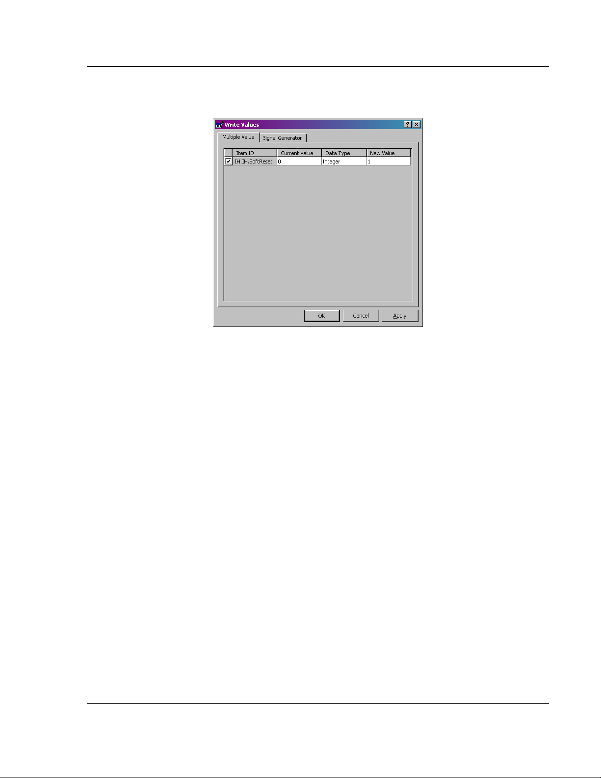
tag is labeled "SoftReset".
This is the example on how to activate the SoftReset tag.
1 Right-Click over the SoftReset Tag. Select the Write Values option.
Page 64 of 108 ProSoft Technology, Inc.
January 22, 2009
Page 65
Connect to Server and Monitor Tags RLX-OPC-SRV ♦ ProSoft Software
RadioLinx® OPC Server for Frequency Hopping and Industrial Hotspot™ Radios
2 Enter 1 into the New Value field and Click OK. This action will reset the
values of the Following Tags: (TAG1, TAG2…)
6.2 RSView Example
6.2.1 Connections
The following procedure will be for a Local Connection.
For the Remote Connection, refer to Step 5. Then follow the identical sequence
as in creating a Local Connection.
ProSoft Technology, Inc. Page 65 of 108
January 22, 2009
Page 66

RLX-OPC-SRV ♦ ProSoft Software Connect to Server and Monitor Tags
RadioLinx® OPC Server for Frequency Hopping and Industrial Hotspot™ Radios
1 In this example the SE Stand-alone is being demonstrated. Click on
Continue button.
2 Enter a desired OPC Client name into the "Application Name:" field. Click
on Create.
Page 66 of 108 ProSoft Technology, Inc.
January 22, 2009
Page 67

Connect to Server and Monitor Tags RLX-OPC-SRV ♦ ProSoft Software
RadioLinx® OPC Server for Frequency Hopping and Industrial Hotspot™ Radios
3 After about a minute the following window is generated by RSView Studio
program.
4 Right Click over the RadioLinx_OPC_Client branch to select the
RadioLinx OPC Server.
ProSoft Technology, Inc. Page 67 of 108
January 22, 2009
Page 68

RLX-OPC-SRV ♦ ProSoft Software Connect to Server and Monitor Tags
RadioLinx® OPC Server for Frequency Hopping and Industrial Hotspot™ Radios
5 Enter a desired name for the OPC Data Server.
Select Local server host, then click on Browse button to select RadioLinx
OPC Server in installed in the Local Computer.
- or Select Remote server host, then click on Browse button to select RadioLinx
OPC Server in installed in the Remote Computer.
6 Select the RadioLinx_OPC_Server and Click OK.
Page 68 of 108 ProSoft Technology, Inc.
January 22, 2009
Page 69

Connect to Server and Monitor Tags RLX-OPC-SRV ♦ ProSoft Software
RadioLinx® OPC Server for Frequency Hopping and Industrial Hotspot™ Radios
7 Proper OPC Server has been browsed for and selected. Click OK.
The appropriate OPC Server has been added to the project.
ProSoft Technology, Inc. Page 69 of 108
January 22, 2009
Page 70

RLX-OPC-SRV ♦ ProSoft Software Connect to Server and Monitor Tags
RadioLinx® OPC Server for Frequency Hopping and Industrial Hotspot™ Radios
8 Right click over Tags to start creating RSView tags that will be connected to
the RadioLinx OPC Server. Select Open.
Page 70 of 108 ProSoft Technology, Inc.
January 22, 2009
Page 71

Connect to Server and Monitor Tags RLX-OPC-SRV ♦ ProSoft Software
RadioLinx® OPC Server for Frequency Hopping and Industrial Hotspot™ Radios
ProSoft Technology, Inc. Page 71 of 108
January 22, 2009
Page 72

RLX-OPC-SRV ♦ ProSoft Software Connect to Server and Monitor Tags
RadioLinx® OPC Server for Frequency Hopping and Industrial Hotspot™ Radios
9 Enter the desired tag name into "Name:" field. Select the RSView Tag Type.
Click on the Data Source Address selection button.
Page 72 of 108 ProSoft Technology, Inc.
January 22, 2009
Page 73

Connect to Server and Monitor Tags RLX-OPC-SRV ♦ ProSoft Software
RadioLinx® OPC Server for Frequency Hopping and Industrial Hotspot™ Radios
10 Right-click over the selected branch and select Refresh All Folders.
11 Expand the branches and select TotBytFwd RadioLinx OPC Server Tag
name. Click OK to continue.
ProSoft Technology, Inc. Page 73 of 108
January 22, 2009
Page 74

RLX-OPC-SRV ♦ ProSoft Software Connect to Server and Monitor Tags
RadioLinx® OPC Server for Frequency Hopping and Industrial Hotspot™ Radios
12 The RSView Tag name Total_Bytes_Forward has been linked to the
RadioLinx OPC Server tag name TotBytFwd. In the Tag group select the
(Default) Data Type. Click Accept to Continue.
13 Enter another tag name into Name: field. Select the RSView Tag Type. Click
on the Data Source Address selection button.
Page 74 of 108 ProSoft Technology, Inc.
January 22, 2009
Page 75

Connect to Server and Monitor Tags RLX-OPC-SRV ♦ ProSoft Software
RadioLinx® OPC Server for Frequency Hopping and Industrial Hotspot™ Radios
14 Select ResetStats RadioLinx OPC Server Tag name. Click OK.
15 After clicking on the Accept button, the second sample RSView tag name has
been linked with the second RadioLinx OPC Server Tag name (as indicated
in this screen capture). Click Close.
16 Let's create a display for the two tags link.
Getting ready to create two tag displays.
ProSoft Technology, Inc. Page 75 of 108
January 22, 2009
Page 76

RLX-OPC-SRV ♦ ProSoft Software Connect to Server and Monitor Tags
RadioLinx® OPC Server for Frequency Hopping and Industrial Hotspot™ Radios
17 Selecting the RSView tag that has already been linked its RadioLinx OPC
Server Tag.
Page 76 of 108 ProSoft Technology, Inc.
January 22, 2009
Page 77

Connect to Server and Monitor Tags RLX-OPC-SRV ♦ ProSoft Software
RadioLinx® OPC Server for Frequency Hopping and Industrial Hotspot™ Radios
18 Formatting the appearance of the RSView Tag.
ProSoft Technology, Inc. Page 77 of 108
January 22, 2009
Page 78

RLX-OPC-SRV ♦ ProSoft Software Connect to Server and Monitor Tags
RadioLinx® OPC Server for Frequency Hopping and Industrial Hotspot™ Radios
19 Formatting of the RSView Text Property.
Page 78 of 108 ProSoft Technology, Inc.
January 22, 2009
Page 79

Connect to Server and Monitor Tags RLX-OPC-SRV ♦ ProSoft Software
RadioLinx® OPC Server for Frequency Hopping and Industrial Hotspot™ Radios
20 One Tag's label and RadioLinx OPC Server link has been created.
ProSoft Technology, Inc. Page 79 of 108
January 22, 2009
Page 80

RLX-OPC-SRV ♦ ProSoft Software Connect to Server and Monitor Tags
RadioLinx® OPC Server for Frequency Hopping and Industrial Hotspot™ Radios
21 Select the appropriate RSView tag to display the RadioLinx OPC tag's value.
22 In this example the value must be set to 1.
Page 80 of 108 ProSoft Technology, Inc.
January 22, 2009
Page 81

Connect to Server and Monitor Tags RLX-OPC-SRV ♦ ProSoft Software
RadioLinx® OPC Server for Frequency Hopping and Industrial Hotspot™ Radios
23 Either Press Action or Release Action may be used.
ProSoft Technology, Inc. Page 81 of 108
January 22, 2009
Page 82

RLX-OPC-SRV ♦ ProSoft Software Connect to Server and Monitor Tags
RadioLinx® OPC Server for Frequency Hopping and Industrial Hotspot™ Radios
24 Appearance of the Total Bytes Forward tag's appearance and the Reset
Statistics button appearance in the Edit window.
Page 82 of 108 ProSoft Technology, Inc.
January 22, 2009
Page 83

Connect to Server and Monitor Tags RLX-OPC-SRV ♦ ProSoft Software
RadioLinx® OPC Server for Frequency Hopping and Industrial Hotspot™ Radios
25 Activating the Run Mode. Observe the display of the Total bytes Forward
Tag's value as polled by the RSView's OPC Client Run window from the
RadioLinx OPC Server communicating to RLX-FHE radio. Click on the Reset
Statistics button to reset the value of the Total Bytes Forward tag.
ProSoft Technology, Inc. Page 83 of 108
January 22, 2009
Page 84

RLX-OPC-SRV ♦ ProSoft Software Connect to Server and Monitor Tags
RadioLinx® OPC Server for Frequency Hopping and Industrial Hotspot™ Radios
26 The question marks may or may not show up for a few seconds. It will
depend on the Ethernet traffic.
Page 84 of 108 ProSoft Technology, Inc.
January 22, 2009
Page 85

Connect to Server and Monitor Tags RLX-OPC-SRV ♦ ProSoft Software
RadioLinx® OPC Server for Frequency Hopping and Industrial Hotspot™ Radios
27 After a few seconds notice the lower value for the Total Bytes Forward tag.
We are not able to observe a value of 0 (zero) because, by the time RLXFHE radio receives the Command to reset its statistics to the time the Radio
receives the pole request from RSView OPC Client to display the reset value,
the radio has already incremented it's Total Bytes Forward count.
ProSoft Technology, Inc. Page 85 of 108
January 22, 2009
Page 86

RLX-OPC-SRV ♦ ProSoft Software Connect to Server and Monitor Tags
RadioLinx® OPC Server for Frequency Hopping and Industrial Hotspot™ Radios
6.3 WonderWare Example
1 Select or expand the DAServer Manager.
2 Start a new Node Group
3 Give the Node Group a name.
Page 86 of 108 ProSoft Technology, Inc.
January 22, 2009
Page 87

Connect to Server and Monitor Tags RLX-OPC-SRV ♦ ProSoft Software
RadioLinx® OPC Server for Frequency Hopping and Industrial Hotspot™ Radios
4 Start the selection of a Node (PC in the network) in the Group.
5 Click Browse to see the available Nodes (PCs in the network) that will contain
the RadioLinx OPC Server.
6 Select the desired Node, and then click OK to make the connection to the
selected Node.
ProSoft Technology, Inc. Page 87 of 108
January 22, 2009
Page 88

RLX-OPC-SRV ♦ ProSoft Software Connect to Server and Monitor Tags
RadioLinx® OPC Server for Frequency Hopping and Industrial Hotspot™ Radios
7 Expand the Node Tree and right-click on the "Add OPC Client."
8 Name the configuration in the left pane and in the right pane for the 'Server
Name:' field select RadioLinx_OPC_Server. Then click on the blue floppy
icon to save the configuration.
Page 88 of 108 ProSoft Technology, Inc.
January 22, 2009
Page 89

Connect to Server and Monitor Tags RLX-OPC-SRV ♦ ProSoft Software
RadioLinx® OPC Server for Frequency Hopping and Industrial Hotspot™ Radios
9 Add an OPCGroup Object to the newly created configuration.
10 New OPC group has been created. Click on the 'Browse OPC Items' button
to select tags from the RadioLinx OPC Server.
ProSoft Technology, Inc. Page 89 of 108
January 22, 2009
Page 90

RLX-OPC-SRV ♦ ProSoft Software Connect to Server and Monitor Tags
RadioLinx® OPC Server for Frequency Hopping and Industrial Hotspot™ Radios
11 Expand the Selected OPC Server Tree. In the upper right pane, select all
Tags and right-click to add the OPC Server Tags to the Basket.
12 Click OK to add the Tags in the Basket to the Device Items.
Page 90 of 108 ProSoft Technology, Inc.
January 22, 2009
Page 91

Connect to Server and Monitor Tags RLX-OPC-SRV ♦ ProSoft Software
RadioLinx® OPC Server for Frequency Hopping and Industrial Hotspot™ Radios
Tags have been added to the OPC group.
13 Rename the desired OPC Server Tag names with more descriptive names.
This completes the RadioLinx OPC Connection to the Wonderware OPC
Client that is to be developed next.
14 Activate the InTouch Application manager.
ProSoft Technology, Inc. Page 91 of 108
January 22, 2009
Page 92

RLX-OPC-SRV ♦ ProSoft Software Connect to Server and Monitor Tags
RadioLinx® OPC Server for Frequency Hopping and Industrial Hotspot™ Radios
15 Select where to develop the new application.
16 Create a Directory name for the OPC Client application.
17 Create the new application name.
Page 92 of 108 ProSoft Technology, Inc.
January 22, 2009
Page 93

Connect to Server and Monitor Tags RLX-OPC-SRV ♦ ProSoft Software
RadioLinx® OPC Server for Frequency Hopping and Industrial Hotspot™ Radios
18 The application new name has been created. Start Window Maker
application.
19 In WindowMaker open up the Tagname Dictionary and crate an appropriate
InTouch tag name for connecting to the RadioLinx OPC Server tag name.
20 In the "Topic Name:" field enter the name as shown in "Device Group Name:"
in the OPC Group tab.
ProSoft Technology, Inc. Page 93 of 108
January 22, 2009
Page 94

RLX-OPC-SRV ♦ ProSoft Software Connect to Server and Monitor Tags
RadioLinx® OPC Server for Frequency Hopping and Industrial Hotspot™ Radios
21 Select the appropriate Access Name.
22 The InTouch Tag name to the RadioLinx OPC Server tag name.
23 Create a display that links the InTouch tag name to the RLX OPC Server tag
name.
Page 94 of 108 ProSoft Technology, Inc.
January 22, 2009
Page 95

Connect to Server and Monitor Tags RLX-OPC-SRV ♦ ProSoft Software
RadioLinx® OPC Server for Frequency Hopping and Industrial Hotspot™ Radios
24 Click on the selected Analog button.
25 Double-click in the Expression: field.
26 Select the desired InTouch Tag name. The selected tag enters the
expression field.
ProSoft Technology, Inc. Page 95 of 108
January 22, 2009
Page 96

RLX-OPC-SRV ♦ ProSoft Software Connect to Server and Monitor Tags
RadioLinx® OPC Server for Frequency Hopping and Industrial Hotspot™ Radios
27 Connecting the button to the Reset_Statistics tag.
28 Create button and the link from InTouch Client tag to RadioLinx OPCServer
tag.
29 Double-Click in the large empty field. Select the appropriate InTouch tag.
Page 96 of 108 ProSoft Technology, Inc.
January 22, 2009
Page 97

Connect to Server and Monitor Tags RLX-OPC-SRV ♦ ProSoft Software
RadioLinx® OPC Server for Frequency Hopping and Industrial Hotspot™ Radios
ProSoft Technology, Inc. Page 97 of 108
January 22, 2009
Page 98

RLX-OPC-SRV ♦ ProSoft Software Connect to Server and Monitor Tags
RadioLinx® OPC Server for Frequency Hopping and Industrial Hotspot™ Radios
30 Set the controlling tag to a value of 1 that will issue the resetting command to
the radio.
31 Run-Time view of the two tags. You are finished.
Page 98 of 108 ProSoft Technology, Inc.
January 22, 2009
Page 99

Support, Service & Warranty RLX-OPC-SRV ♦ ProSoft Software
RadioLinx® OPC Server for Frequency Hopping and Industrial Hotspot™ Radios
7 Support, Service & Warranty
In This Chapter
How to Contact Us: Technical Support..................................................99
Return Material Authorization (RMA) Policies and Conditions.............100
LIMITED WARRANTY.........................................................................101
ProSoft Technology, Inc. (ProSoft) is committed to providing the most efficient
and effective support possible. Before calling, please gather the following
information to assist in expediting this process:
1 Product Version Number
2 System architecture
3 Network details
If the issue is hardware related, we will also need information regarding:
1 Module configuration and contents of file
o Module Operation
o Configuration/Debug status information
o LED patterns
2 Information about the processor and user data files as viewed through and
LED patterns on the processor.
3 Details about the serial devices interfaced, if any.
7.1 How to Contact Us: Technical Support
Internet
Asia Pacific
+603.7724.2080, support.asia@prosoft-technology.com
Languages spoken include: Chinese, English
Europe (location in Toulouse, France)
+33 (0) 5.34.36.87.20, support.EMEA@prosoft-technology.com
Languages spoken include: French, English
North America/Latin America (excluding Brasil) (location in California)
+1.661.716.5100, support@prosoft-technology.com
Languages spoken include: English, Spanish
For technical support calls within the United States, an after-hours answering system allows pager
access to one of our qualified technical and/or application support engineers at any time t o answer
your questions.
Brasil (location in Sao Paulo)
+55-11-5084-5178 , eduardo@prosoft-technology.com
Languages spoken include: Portuguese, English
Web Site: http://www.prosoft-technology.com/support
E-mail address: support@prosoft-technology.com
ProSoft Technology, Inc. Page 99 of 108
January 22, 2009
Page 100

RLX-OPC-SRV ♦ ProSoft Software Support, Service & Warranty
RadioLinx® OPC Server for Frequency Hopping and Industrial Hotspot™ Radios
7.2 Return Material Authorization (RMA) Policies and Conditions
The following RMA Policies and Conditions (collectively, "RMA Policies") apply to
any returned Product. These RMA Policies are subject to change by ProSoft
without notice. For warranty information, see "Limited Warranty". In the event of
any inconsistency between the RMA Policies and the Warranty, the Warranty
shall govern.
7.2.1 All Product Returns:
a) In order to return a Product for repair, exchange or otherwise, the
Customer must obtain a Returned Material Authorization (RMA) number
from ProSoft and comply with ProSoft shipping instructions.
b) In the event that the Customer experiences a problem with the Product for
any reason, Customer should contact ProSoft Technical Support at one of
the telephone numbers listed above (page 99). A Technical Support
Engineer will request that you perform several tests in an attempt to
isolate the problem. If after completing these tests, the Product is found to
be the source of the problem, we will issue an RMA.
c) All returned Products must be shipped freight prepaid, in the original
shipping container or equivalent, to the location specified by ProSoft, and
be accompanied by proof of purchase and receipt date. The RMA number
is to be prominently marked on the outside of the shipping box. Customer
agrees to insure the Product or assume the risk of loss or damage in
transit. Products shipped to ProSoft using a shipment method other than
that specified by ProSoft or shipped without an RMA number will be
returned to the Customer, freight collect. Contact ProSoft Technical
Support for further information.
d) A 10% restocking fee applies to all warranty credit returns whereby a
Customer has an application change, ordered too many, does not need,
etc.
7.2.2 Procedures for Return of Units Under Warranty:
A Technical Support Engineer must approve the return of Product under
ProSoft's Warranty:
a) A replacement module will be shipped and invoiced. A purchase order will
be required.
b) Credit for a product under warranty will be issued upon receipt of
authorized product by ProSoft at designated location referenced on the
Return Material Authorization.
7.2.3 Procedures for Return of Units Out of Warranty:
a) Customer sends unit in for evaluation
b) If no defect is found, Customer will be charged the equivalent of $100
USD, plus freight charges, duties and taxes as applicable. A new
purchase order will be required.
Page 100 of 108 ProSoft Technology, Inc.
January 22, 2009
 Loading...