

Page 1

MVI46-DFNT
SLC Platform
EtherNet/IP Interface Module
User Manual
November 5, 2004
Page 2

Please Read This Notice
Successful application of this module requires a reasonable working knowledge of the SLC Platform
EtherNet/IP Interface Module hardware and the application in which the combination is to be used. For
this reason, it is important that those responsible for implementation satisfy themselves that the
combination will meet the needs of the application without exposing personnel or equipment to unsafe
or inappropriate working conditions.
This manual is provided to assist the user. Every attempt has been made to assure that the information
provided is accurate and a true reflection of the product's installation requirements. In order to assure a
complete understanding of the operation of the product, the user should read all applicable AllenBradley documentation on the operation of the A-B hardware.
Under no conditions will ProSoft Technology, Inc. be responsible or liable for indirect or consequential
damages resulting from the use or application of the product.
Reproduction of the contents of this manual, in whole or in part, without written permission from ProSoft
Technology, Inc. is prohibited.
Information in this manual is subject to change without notice and does not represent a commitment on
the part of ProSoft Technology, Inc. Improvements and/or changes in this manual or the product may be
made at any time. These changes will be made periodically to correct technical inaccuracies or
typographical errors.
ProSoft Technology, Inc.
1675 Chester Avenue, 2
Bakersfield, CA 93301
(661) 716-5100
(661) 716-5101 (Fax)
www.prosoft-technology.com
Copyright © ProSoft Technology, Inc. 2000 – 2004. All Rights Reserved.
MVI46-DFNT User Manual
November 5, 2004
nd
Floor
ProSoft Technology, Inc. Page 2 of 118
November 9, 2004
Page 3

Table of Contents MVI46-DFNT ♦ SLC Platform
EtherNet/IP Interface Module
Table of Contents
PLEASE READ THIS NOTICE..........................................................................................................2
1 INTRODUCTION......................................................................................................................... 5
1.1 Using this Manual........................................................................................................... 5
1.2 Product Specifications...................................................................................................5
1.2.1 General Specifications .................................................................................................. 6
1.2.2 Hardware Specifications ............................................................................................... 7
2 FUNCTIONAL OVERVIEW......................................................................................................... 9
2.1 General Concepts........................................................................................................... 9
2.1.1 Module Power Up ......................................................................................................... 9
2.1.2 Main Logic Loop............................................................................................................ 9
2.1.3 Backplane Data Transfer ............................................................................................ 10
2.2 Module Control Blocks ................................................................................................ 11
2.2.1 Status Data Request................................................................................................... 12
2.2.2 Output Data Initialization Request .............................................................................. 12
2.2.3 Command Error List Request ..................................................................................... 12
2.2.4 Command Control....................................................................................................... 13
2.2.5 Warm Boot .................................................................................................................. 13
2.2.6 Cold Boot .................................................................................................................... 14
2.3 Data Flow between MVI46-DFNT Module and SLC Processor................................. 14
2.3.1 Server Driver............................................................................................................... 14
2.3.2 Client Driver ................................................................................................................ 19
3 MODULE CONFIGURATION ................................................................................................... 21
3.1 Setting Up the Module.................................................................................................. 21
3.2 Module Data..................................................................................................................22
4 LADDER LOGIC.......................................................................................................................23
4.1 Main Routine (U:2)........................................................................................................23
4.2 Data Transfer (U:3).......................................................................................................23
4.3 Control Routine (U:4)...................................................................................................23
5 CONFIGURATION FILE...........................................................................................................29
5.1 Command List Overview..............................................................................................30
5.2 Commands Supported by the Module........................................................................ 30
5.3 Command Entry Formats.............................................................................................31
6 DIAGNOSTICS AND TROUBLESHOOTING........................................................................... 35
6.1 Reading Status Data From the Module ...................................................................... 35
6.1.1 Required Hardware..................................................................................................... 35
ProSoft Technology, Inc. Page 3 of 118
November 9, 2004
Page 4

MVI46-DFNT ♦ SLC Platform Table of Contents
EtherNet/IP Interface Module
6.1.2 Required Software.......................................................................................................36
6.1.3 Using the Port..............................................................................................................36
6.1.4 Menu Options ..............................................................................................................36
6.2 LED Status Indicators...................................................................................................44
6.2.1 Clearing a Fault Condition...........................................................................................46
6.2.2 Troubleshooting...........................................................................................................46
7 CABLE CONNECTIONS...........................................................................................................49
7.1 Ethernet Connection.....................................................................................................49
7.2 Pass-Through Ports......................................................................................................49
7.3 RS-232 Configuration/Debug Port...............................................................................50
8 ETHERNET PORT CONFIGURATION: WATTCP.CFG...........................................................51
APPENDIX A - MVI46-DFNT STATUS DATA DEFINITION............................................................53
APPENDIX B - MVI46-DFNT CONFIGURATION DATA DEFINITION............................................67
APPENDIX C - EXAMPLE DFNT.CFG FILE ...................................................................................73
APPENDIX D: COMMAND FUNCTION CODES.............................................................................75
APPENDIX E: CLIENT CONFIGURATIONS FOR SERVER...........................................................87
RSLinx Software..........................................................................................................................87
DDE Connection ........................................................................................................................89
OPC Connection ........................................................................................................................93
ControlLogix (CLX) Processor...................................................................................................95
Encapsulated PCCC Messages ................................................................................................95
CIP Data Table Operations........................................................................................................98
PLC5 Processor.........................................................................................................................101
PLC5 Write Commands ...........................................................................................................101
PLC5 Read Commands...........................................................................................................102
SLC 5/05 Processor...................................................................................................................104
SLC5/05 Write Commands ......................................................................................................104
SLC5/05 Read Commands......................................................................................................105
RSView Software .......................................................................................................................106
APPENDIX F – ACCESSING AN SLC 5/03 PROCESSOR VIA ETHERNET USING MVI46-DFNT109
Troubleshooting........................................................................................................................112
APPENDIX G - FREQUENTLY ASKED QUESTIONS..................................................................115
APPENDIX H - SUPPORT, SERVICE, AND WARRANTY............................................................117
Page 4 of 118 ProSoft Technology, Inc.
November 9, 2004
Page 5

Introduction MVI46-DFNT ♦ SLC Platform
EtherNet/IP Interface Module
1 Introduction
This manual provides information on the MVI46-DFNT (EtherNet/IP Communication
Module) module.
1.1 Using this Manual
This manual contains the following sections:
Product Specifications
This section provides an overview of the MVI46-DFNT features. These features are
explained later in the following sections.
Functional Overview
This section provides details about how the module functions including how data is
transferred between the module and the SLC. This section also explains the module
control blocks and the supported commands. Finally it describes the server and
client drivers.
Module Configuration
This section describes the MVI46-DFNT configuration file in the RSLogix.
Ladder Logic
This section explains the sample ladder logic. ProSoft Technology, Inc. strongly
suggests that you use the sample ladder logic as a starting point to build your
application.
Configuration File
This section describes the configuration file. It also discusses the command list in
detail. Additional parameters are explained in Appendix B. Appendix C contains a
configuration file example.
Diagnostics and Troubleshooting
The section describes the debug port menu.
Cable Connections
The required cabling is discussed in detail in this section.
Wattcp.cfg
This section presents the Ethernet configuration file, used to set up the module IP
address and other TCP/IP network configurations.
1.2 Product Specifications
The MVI46-DFNT (“EtherNet/IP Communication Module”) product allows AllenBradley SLC I/O compatible processors to easily interface with other EtherNet/IP
protocol compatible devices. Compatible devices include not only Allen-Bradley
controllers but also a wide assortment of other client and server devices. The
following is a list of
Ethernet/IP (Explicit Messaging) Compatible Devices:
ProSoft Technology, Inc. Page 5 of 118
November 9, 2004
Page 6

MVI46-DFNT ♦ SLC Platform Introduction
EtherNet/IP Interface Module
List of A-B material that support EPIC:
• PLC5/E rev C/N, D/E, E/D
• SLC5/05 series A, OS503 frn4
• 1785-ENET Series A, rev D
• Interchange V6.2
• ControlLogix 1756-ENET
• RSLinx Gateway V1.7
1.2.1 General Specifications
The MVI46-DFNT module acts as a gateway between the EtherNet/IP, TCP/IP
network, and the Allen-Bradley backplane. The data transfer from the SLC processor
is asynchronous from the actions on the EtherNet/IP network. A 4000-word register
space in the module is used to exchange data between the processor and the
EtherNet/IP network.
Some of the general specifications include:
• Support for the storage and transfer of up to 4000 registers to/from the SLC
processor’s user data files
• Module memory usage that is completely user-definable
• 10/100 MB Ethernet compatible interface
• Configurable parameters for the client include:
Minimum Response Delay: 0 to 65535 milliseconds
Response Timeout : 1 to 65535 milliseconds
Retry Count: 0 to 20
• The module permits programming of the SLC processor over Ethernet using
a TCP/IP service and a serial port on the module connected to Channel 0 of
the processor. In this configuration, the module’s third port emulates the
Channel 0 of the processor to pass-through messages from the port to the
processor.
1.2.1.1 Server Functional Specifications
The MVI46-DFNT module supports EtherNet/IP explicit, connected and unconnected
class messaging. The 20 servers permit remote clients to interact with all data
contained in the module. This data can be derived from other clients on the network,
through the client on the module, or from the SLC processor.
1.2.1.2 Client Specifications
A client configured as a EtherNet/IP device on the MVI46-DFNT module will actively
issue connected, explicit messages to other nodes on the network. One hundred
(100) user-defined commands are supported for the single client.
1.2.1.3 Pass-Through Services
The module permits remote programming of the SLC processor on the Ethernet
network using the built-in pass-through TCP service and a serial communication port
(pass-through port) on the module. DF1 messages passed from the RSLogix 500
software and RSLinx (using the DF1 serial driver and port redirection software) are
Page 6 of 118 ProSoft Technology, Inc.
November 9, 2004
Page 7

Introduction MVI46-DFNT ♦ SLC Platform
EtherNet/IP Interface Module
placed on the Ethernet network. The module receives these messages and passes
them on to the SLC processor. This permits any node on the network to remotely
program the SLC processor. Only one connection is permitted to prevent confusion
during programming. When this feature is used, the third port on the module can
emulate the Channel 0 port on the SLC. A DF1 master device can be attached to this
port to monitor and control data in the SLC using the serial interface.
1.2.1.4 Physical
This module is designed by ProSoft Technology and incorporates licensed
technology from Allen-Bradley (SLC backplane technology).
• SLC Form Factor - Single Slot
• Connections:
o 1 – RJ45 connector for Ethernet interface
o 1 – RJ45 RS-232 Configuration Tool Connector
o 2 – RJ45 RS-232/485/422 Serial ports for pass-through operations
1.2.1.5 SLC Interface
• Operation via simple ladder logic
• Complete set up and monitoring of module through RSLogix 500 software
and user constructed configuration file (DFNT.CFG)
• SLC backplane interface via M1 file
• All data related to the module is contained in user-defined files and a user
configuration file
1.2.2 Hardware Specifications
The MVI46-DFNT module is designed by ProSoft Technology and incorporates
licensed technology from Allen-Bradley (PLC backplane technology).
• Current Loads: 800 ma @ 5V (from backplane)
• Operating Temperature: 0 to 60 Deg C (32 to 140 Deg F)
• Storage Temperature: -40 to 85 Deg C (-40 to 185 Def F)
• Relative Humidity: 5-95% (w/o condensation)
• Ethernet Connector: One RJ45 Connector
• Configuration Connector: RJ45 RS-232 Connector (RJ45 to DB9 cable
• Pass-Through ports (2): RJ45 RS-232/485/422 Connector (RJ45 to DB9
shipped with unit)
cable shipped with unit)
ProSoft Technology, Inc. Page 7 of 118
November 9, 2004
Page 8

MVI46-DFNT ♦ SLC Platform Introduction
EtherNet/IP Interface Module
Page 8 of 118 ProSoft Technology, Inc.
November 9, 2004
Page 9

Functional Overview MVI46-DFNT ♦ SLC Platform
EtherNet/IP Interface Module
2 Functional Overview
This section gives the reader a functional overview of the MVI46-DFNT module.
A thorough understanding of the information contained in this document is required
for successful implementation of the module in a user application. If you already
understand the content of this section, refer to the Module Configuration section to
get the module up and running. If you are not familiar with the data transfer method
used by the module, read this section before setting up the module.
2.1 General Concepts
The following discussion covers several concepts that are key to understanding the
operation of the MVI46-DFNT module.
2.1.1 Module Power Up
On power up the module begins performing the following logical functions:
1. Initialize hardware components
a. Initialize SLC backplane driver
b. Test and clear all RAM
c. Initialize the serial communication ports
2. Read configuration for module from DFNT.CFG file on Compact Flash Disk
3. Initialize Module Register space
4. Enable Server Drivers
5. Enable Client Driver
6. Initialize all serial communication ports
Once the module receives the configuration, the module begins communicating with
other nodes on the network, depending on the configuration.
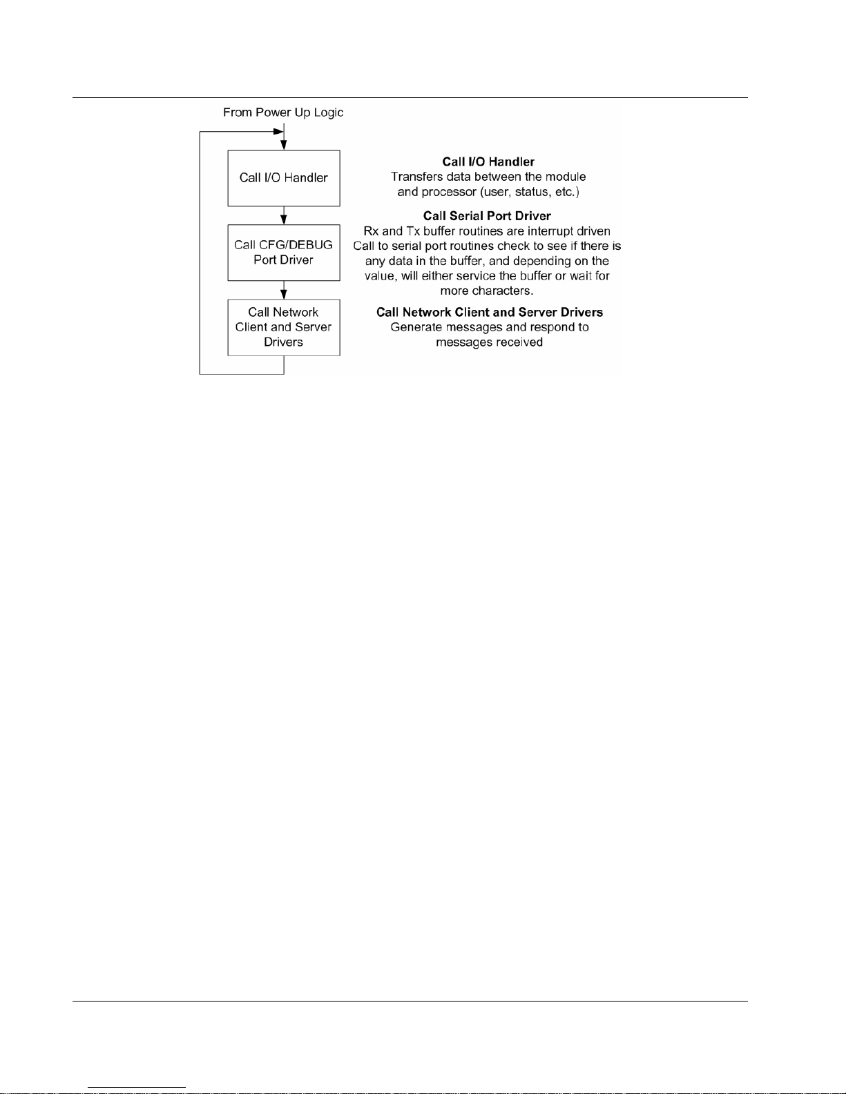
2.1.2 Main Logic Loop
Upon completing the power up configuration process, the module enters an infinite
loop that performs the functions shown in the following diagram.
ProSoft Technology, Inc. Page 9 of 118
November 9, 2004
Page 10
MVI46-DFNT ♦ SLC Platform Functional Overview
EtherNet/IP Interface Module
2.1.3 Backplane Data Transfer
The MVI46-DFNT module is unique in the way that the SLC backplane is used. All
data for the module is contained in the module’s M1 file. Data is moved between the
module and the SLC processor across the backplane using the module’s M1 file. The
SLC scan rate and the communication load on the module determine the update
frequency of the M1 file. The COP instruction can be used to move data between
user data files and the module’s M1 file.
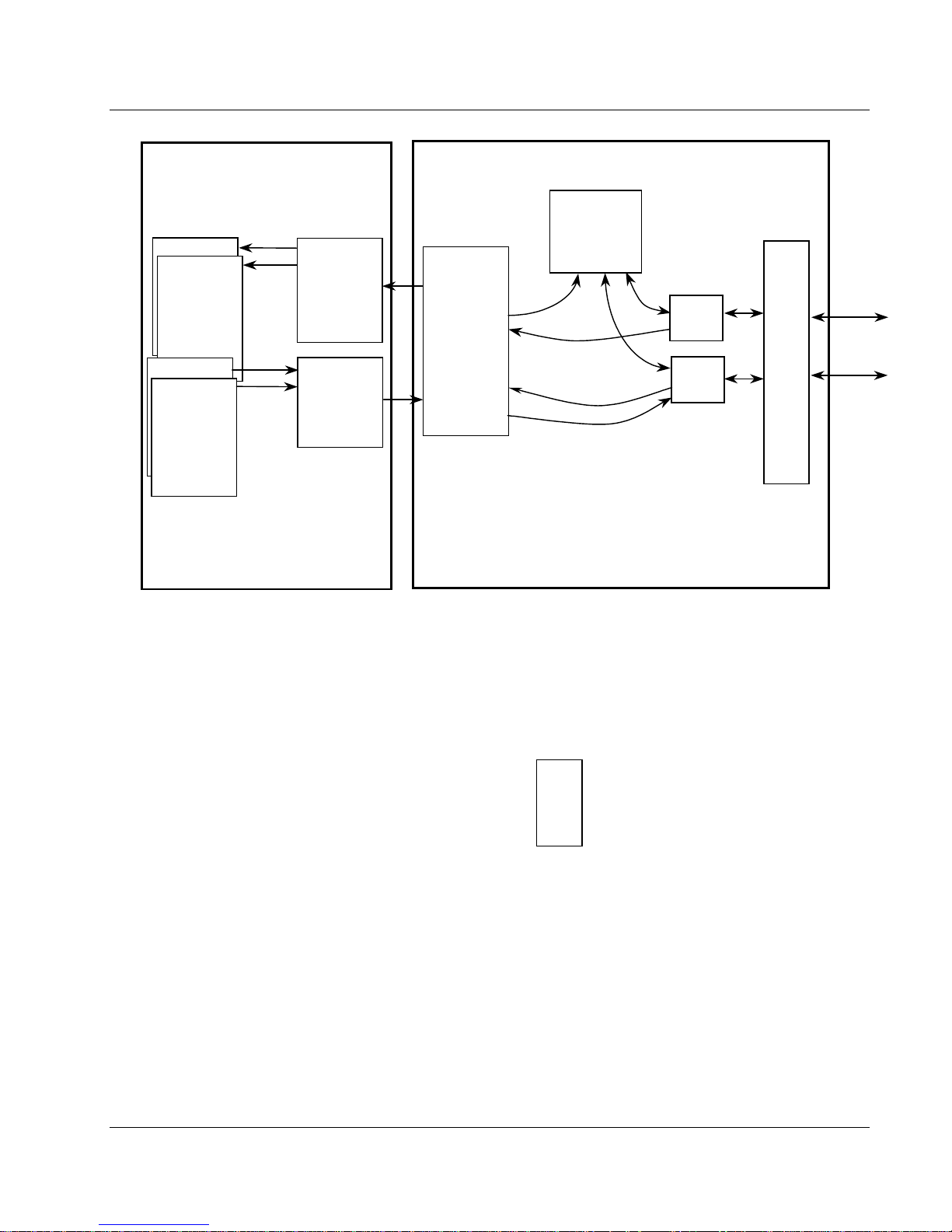
The following diagram displays the data transfer method used to move data between
the SLC processor, the MVI46-DFNT module, and the TCP/IP Network.
Page 10 of 118 ProSoft Technology, Inc.
November 9, 2004
Page 11
Functional Overview MVI46-DFNT ♦ SLC Platform
EtherNet/IP Interface Module
User Data Files
Status
Read Data
Write Data
Special Control
Blocks
SLC Processor
Ladder
Logic
Transfers
Data from
module’s M1
File to data
areas in the
processor
Ladder
Logic
Transfers
Data from
Processor
data areas
to M1 File
MVI46-DFNT Mo d ul e
Module’s
Internal
Database
Server
Server
Driver
Driver
Logic
M1 File
Backplane Driver
Command Control
Logic
Client
Client
Driver
Driver
Logic
Logic
TCP/IP
Stack
And
Ethernet
Interface
To
EtherNet/IP
Network
As shown in the diagram, all data transferred between the module and the processor
over the backplane is through the M1 file. Ladder logic must be written in the SLC
processor to interface the M1 file data in the module’s internal database. All data
used by the module is stored in its internal database. The following diagram shows
the layout of the database:
Module’s Internal Database Structure
4000 registers for user data
1000 registers for command
control
Data registers in the module above 3999 are used for command control. When
special values are written in this register set, the module performs specific functions.
The following sections define the special functions handled by the module.
2.2 Module Control Blocks
As discussed in the previous section, range 4000 to 4999 in the M1 file is used to
control the module in order to perform specific tasks. These tasks are described in
the following sections. Word 4000 contains the block ID that identifies the block to
the MVI46-DFNT module. The block structure, which is different for each block, is
shown in the following sections.
M1 File
0
3999
4999
ProSoft Technology, Inc. Page 11 of 118
November 9, 2004
Page 12

MVI46-DFNT ♦ SLC Platform Functional Overview
EtherNet/IP Interface Module
2.2.1 Status Data Request
When the user wants to read the module’s general error and status data to the SLC,
it must make a special request using the command control area. The following tables
lists the two values recognized by the module in register 4000 to request the data:
Control Code Content Description
250 General
251 DFNT Servers
Status data for the module, client
and pass-through server
Status data for each of the 5
DFNT servers
Appendix A of this document contains a complete listing of the data returned for the
two status blocks.
2.2.2 Output Data Initialization Request
When the module performs a restart operation, it requests output data from the
processor to initialize the module’s output data. This mode of operation is selected
using the Initialize Output Data parameter in the configuration file. This facility can
be used to bring the module to a known state after the restart operation. The
structure of the block used to request the data is shown in the following table:
Offset Description / Value Length
4000 1000 1
The command control value of 1000 is placed in register 4000 of the M1 file to
indicate that the module is requesting initialization of the M1 data file. Ladder logic in
the processor must recognize this command and place the correct information in the
M1file. After the data transfer is complete, the ladder logic should place a value of
1001 in register 4000 of the module’s M1 file. The format of the returned write block
is shown in the following table:
Offset Description / Value Length
4000 1001 1
2.2.3 Command Error List Request
This command control request (control code of 2000) is used to request a set of data
from the command list error data set. The error codes returned in the block are
DFNT error codes noted in Appendix A. The format of the request block from the
ladder logic has the following format:
M1-File Offset Description
4000 This field contains the command code value of 2000
4001
4002
This field contains the starting command index for the first error to report.
This field has a range of 0 to 99.
This field contains the number of command error list values to report in
the response block. This register has a range from 1 to 60.
Page 12 of 118 ProSoft Technology, Inc.
November 9, 2004
Page 13

Functional Overview MVI46-DFNT ♦ SLC Platform
EtherNet/IP Interface Module
After the module processes the block, it supplies the following values in the control
register area:
M1-File Offset Description
4000 This field will be set to a value of 0 to indicate the function is complete.
4001 This field contains the command code value of 2000 requested
4002
4003
4004 to 4063
This field contains the starting command index reported in the response
block.
This field contains the number of command error list values in the
response block.
This data area contains the error codes for each of the command in the
module.
2.2.4 Command Control
Blocks 3000 to 3002 are used to alter the command type field for a set of commands
in the client command lists. Block 3000 is used to disable commands by setting the
enable type field to value of 0. Block 3001 is used to enable commands by setting
the enable type field to a value of 1. The commands will be issued at the time interval
no more frequent than set in the poll interval parameter for the command. Block 3002
is used to set the enable type field to a value of 2. This operation should only be
used for write functions as the command is only executed when the data referenced
by the command changes. The general format for the blocks is as follows:
M1-File Offset Description
4000 This field contains the command code value of 3000 to 3002
4001
4002
After the module processes the block, it supplies the following values in the control
register area:
M1-File Offset Description
4000 This field will be set to a value of 0 to indicate the function is complete.
4001 This field contains the command code value of 3000 to 3002 requested
4002 This field contains the number of commands processed by the module.
2.2.5 Warm Boot
This block is sent from the SLC processor to the module when the module is
required to perform a warm-boot (software reset) operation. This block is commonly
sent to the module any time configuration data modifications are made in the
controller tags data area. This forces the module to read the new configuration
information and to restart. The structure of the control block is shown in the following
table:
This field contains the number of commands from the first command
defined in the 4001 register to apply the new code. The register has a
range of 1 to 60..
This field contains the starting command index to apply the new enable
type code to. This field has a range of 0 to 99.
ProSoft Technology, Inc. Page 13 of 118
November 9, 2004
Page 14
MVI46-DFNT ♦ SLC Platform Functional Overview
EtherNet/IP Interface Module
Offset Description / Value Length
4000 9998 1
2.2.6 Cold Boot
This block is sent from the SLC processor to the module when the module is
required to perform the cold boot (hardware reset) operation. This block is sent to the
module when a hardware problem is detected by the ladder logic that requires a
hardware reset. The structure of the control block is shown in the following table:
Offset Description / Value Length
4000 9999 1
2.3 Data Flow between MVI46-DFNT Module and SLC Processor
The following discussion outlines the flow of data between the two pieces of
hardware (SLC processor and MVI46-DFNT module) and other nodes on the TCP/IP
network under the module’s different operating modes. The module contains both
servers and a client. The servers are used to accept TCP/IP connections on service
port AF12. The client establishes connections to service port AF12 (hexadecimal) on
other EtherNet/IP servers.
The following sections discuss the operation of the server and client drivers.
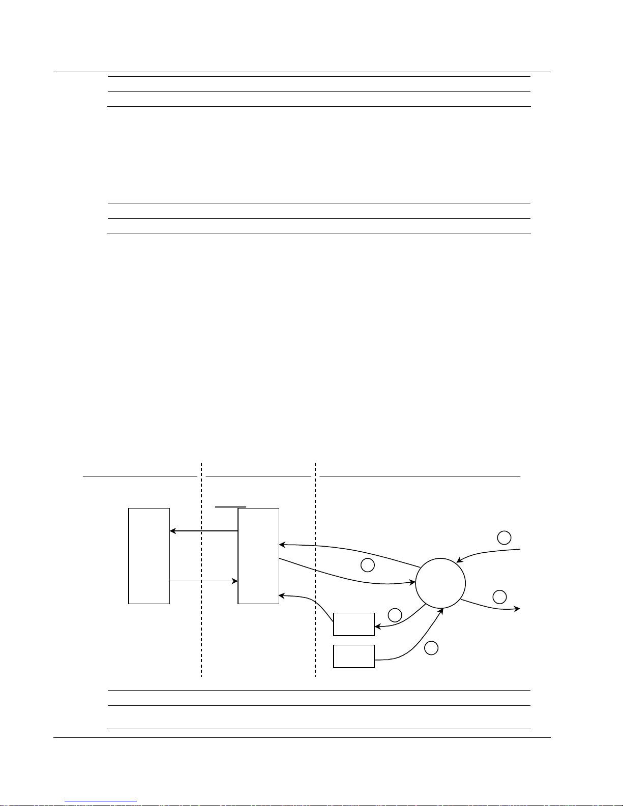
2.3.1 Server Driver
The Server Driver allows the MVI46-DFNT module to respond to data read and write
commands issued by clients on the EtherNet/IP network using explicit messaging.
The following flow chart and associated table describe the flow of data into and out of
the module.
Processor Memory DFNT ModuleBackplane Interf ace
Database
Addresses
0
Register
Data
storage
3999
4999
M1 File
Status
Configuration
2
3
Server
Driver
5
1
4
Step
1 The server driver receives the configuration information from the configuration file on the Compact
Description
Flash Disk, and the module initializes the servers.
Page 14 of 118 ProSoft Technology, Inc.
November 9, 2004
Page 15

Functional Overview MVI46-DFNT ♦ SLC Platform
EtherNet/IP Interface Module
Step
2 A Host device, such as a ControlLogix processor, RSLinx or an MMI package issues a read or write
3 Once the module accepts the command, the data is immediately transferred to or from the internal
4 Once the data processing has been completed in Step 3, the response is issued to the originating
5 Status data for the servers is passed to the processor under ladder logic control using the command
Description
command to the module. The server driver qualifies the message before accepting it into the module.
database in the module. If the command is a read command, the data is read out of the database and a
response message is built. If the command is a write command, the data is written directly into the
database and the M1 file and a response message is built.
master node.
control data area in the M1 file.
The DFNT module supports server functionality using the reserved ControlNet
service port 0xAF12. Services supported in the module permit client applications
(i.e., RSView, ControlLogix processors, and RSLinx) to read from and write to the
module’s database. This section discusses the requirements for attaching to the
module using several client applications.
The following diagram displays the relationship of the DFNT module’s functionality to
devices on an Ethernet network:
DDE/ OP C
RSS ql
Apps
SoftLogix
RSV iew
RSLinx
ControlLogix
Process or
PLC5
Process or
ClientServer
DB
DFNT MODULE
SLC5/05
Processor
Server functionality is used to place all data transfer operations outside the module.
There is no configuration required in the module other than setting up the network
and database parameters in the user configuration file. Ladder logic in attached
processors use MSG instructions to perform read and write operations on the
module’s internal database. When RSLinx is used to link a user application to the
module, the module’s server functionality must be used. RSLinx exists on an
Ethernet network only as a client application. It cannot act as a server. User
applications can use the DDE/OPC capabilities built into RSLinx to interface with the
ProSoft Technology, Inc. Page 15 of 118
November 9, 2004
Page 16

MVI46-DFNT ♦ SLC Platform Functional Overview
EtherNet/IP Interface Module
data in the DFNT module. RSView can link directly to the module using drivers
supplied by RSLinx.
The internal database of the DFNT module is used as the source (read requests)
and destination (write requests) for requests from remote clients. Access to the
database is dependent on the MSG command type executed to interface with the
database. The following table defines the relationship of the module’s internal
database to the addresses required in the MSG instructions:
MSG INSTRUCTION TYPE
DATABASE PLC2 PLC5 OR CONTROLLOGIX
ADDRESS SLC PCCC CIP Integer
0 0 N10:0 N10:0 Int_data[0]
999 999 N10:999 N10:999 Int_data[999]
1000 1000 N11:0 N11:0 Int_data[1000]
1999 1999 N11:999 N11:999 Int_data[1999]
2000 2000 N12:0 N12:0 Int_data[2000]
2999 2999 N12:999 N12:999 Int_data[2999]
3000 3000 N13:0 N13:0 Int_data[3000]
4000 4000 N14:0 N14:0 Int_data[4000]
When using PLC5 or SLC commands, access to the database is through simulated
‘N’ files. For example, to access database element 3012, use the file address of
N13:12. The module simulates N-files in the internal database. The following table
lists the relationship between the N-files and the module’s internal database
registers:
Internal Simulated
Database N-File
Register
0 N10:0
1 N10:1
---
999 N10:999
1000 N11:0
1001 N11:1
---
1999 N11:999
2000 N12:0
2001 N12:1
---
2999 N12:999
3000 N13:0
3001 N13:1
---
3999 N13:999
Page 16 of 118 ProSoft Technology, Inc.
November 9, 2004
Page 17

Functional Overview MVI46-DFNT ♦ SLC Platform
EtherNet/IP Interface Module
Note: The way the data files are used will depend on the DFNT Server File Size
value (100 or 1000). The previous example shows an example where this parameter
is set with a value of 1000.The following table lists the PCCC functions supported by
the module:
Basic Command Set Functions
Command Function Definition
0x00 N/A Protected Write
0x01 N/A Unprotected Read
0x02 N/A Protected Bit Write
0x05 N/A Unprotected Bit Write
0x08 N/A Unprotected Write
PLC-5 Command Set Functions
Command Function Definition
0x0F 0x00 Word Range Write (Binary Address)
0x0F 0x01 Word Range Read (Binary Address)
0x0F 0x00 Word Range Write (ASCII Address)
0x0F 0x01 Word Range Read (ASCII Address)
SLC-500 Command Set Functions
Command Function Definition
0x0F 0xA1
0x0F 0XA2
0x0F 0XA9
0x0F 0XAA
Protected Typed Logical Read With
Two Address Fields
Protected Typed Logical Read With
Three Address Fields
Protected Typed Logical Write With
Two Address Fields
Protected Typed Logical Write With
Three Address Fields
Additionally, the module supports CIP data table read and write functions. These
functions use controller tags to access data in the module’s database. This is the
preferred data access method as it directly specifies the data type used with the
command. The following table lists the data access methods:
ProSoft Technology, Inc. Page 17 of 118
November 9, 2004
Page 18

MVI46-DFNT ♦ SLC Platform Functional Overview
y
EtherNet/IP Interface Module
SERVER DATABASE ACCESS
DATABASE PLC2 PLC5 OR
ADDRESS SLC PCCC CIP CIP CIP CIP CIP CIP
0 0 N10:0 N10:0 BoolData[0] BitAData[0] SintData[0] Int_Data[0] DIntData[0] RealData[0]
999 999 N10:999 N10:999 BoolData[15984] SintData[1998] Int_Data[999]
1000 1000 N11:0 N11:0 BoolData[16000] BitAData[500] SintData[2000] Int_Data[1000] DIntData[500] RealData[500]
1999 1999 N11:999 N11:999 BoolData[31984] SintData[3998] Int_Data[1999]
2000 2000 N12:0 N12:0 BoolData[32000] BitAData[1000] SintData[4000] Int_Data[2000] DIntData[1000] RealData[1000]
2999 2999 N12:999 N12:999 BoolData[47984] SintData[5998] Int_Data[2999]
3000 3000 N13:0 N13:0 BoolData[48000] BitAData[1500] SintData[6000] Int_Data[3000] DIntData[1500] RealData[1500]
3998 3998 N13:998 N13:998 BoolData[63968] BitAData[1999] SintData[7996] Int_Data[3998] DIntData[1999] RealData[1999]
3999 3999 N13:998 N13:999 BoolData[63984] SintData[7998] Int_Data[3999]
Boolean Bit Arra
MSG INSTRUCTION TYPE
CONTROLLOGIX
Byte Integer Double Int Real
If the CIP data table read and write functions are utilized, the controller tag array
names defined in the module must be used. The following table lists the controller
tag names recognized by the module and the associated data types:
Tag Array Data Type Data Size
BoolData[] Bit 1-bit
BitAData[] Bit Array 32-bits
SintData[] Byte 8-bits
Int_Data[] Word 16-bits
DIntData[] Double Word 32-bits
RealData[] Floating-point 32-bits
The following table shows the supported commands when the module acts as a
slave (server):
Basic Command Set Functions
Command Function Definition
Supported
in Slave
0x00 N/A Protected Write X
0x01 N/A Unprotected Read X
0x02 N/A Protected Bit Write X
0x05 N/A Unprotected Bit Write X
0x08 N/A Unprotected Write X
PLC-5 Command Set Functions
Command Function Definition
0x0F 0x00 Word Range Write (Binary Address) X
0x0F 0x01 Word Range Read (Binary Address) X
0x0F Typed Range Read (Binary Address) X
0x0F Typed Range Write (Binary Address) X
0x0F 0x26 Read-Modify-Write (Binary Address)
0x0F 0x00 Word Range Write (ASCII Address) X
0x0F 0x01 Word Range Read (ASCII Address) X
0x0F 0x26 Read-Modify-Write (ASCII Address)
Supported
in Slave
Page 18 of 118 ProSoft Technology, Inc.
November 9, 2004
Page 19

Functional Overview MVI46-DFNT ♦ SLC Platform
EtherNet/IP Interface Module
SLC-500 Command Set Functions
Command Function Definition
Supported
in Slave
0x0F 0xA1 Protected Typed Logical Read With Two Address Fields X
0x0F 0XA2
Protected Typed Logical Read With Three Address
X
Fields
0x0F 0XA9 Protected Typed Logical Write With Two Address Fields X
0x0F 0XAA
Protected Typed Logical Write With Three Address
X
Fields
0x0F 0XAB
Protected Typed Logical Write With Mask (Three
Address Fields)
2.3.2 Client Driver
In the client driver, the MVI46-DFNT module is responsible for issuing read or write
commands to servers on the EtherNet/IP network using explicit, connected
messaging. These commands are user configured in the module via the Client
Command List received from the module’s configuration file (DFNT.CFG). Command
status is returned to the processor for each individual command in the command list
status block in the command control data area. Ladder logic is responsible for
acquiring this data from the module. The following flow chart and associated table
show the flow of data into and out of the module.
Processor Memory Backplane In terface
Database
Addresses
0
Register
Data
storage
3999
Command
Control
4999
M1 File
4
Status
Configuration
Command
Control
DFNT Module
5
4
Command List
Client
Client
Driver
1
3
2
ProSoft Technology, Inc. Page 19 of 118
November 9, 2004
Page 20

MVI46-DFNT ♦ SLC Platform Functional Overview
EtherNet/IP Interface Module
Step Description
1
2
3
4
5
The client driver obtains configuration data from the DFNT.CFG file when the module
restarts. The configuration data obtained includes the timeout parameters and the
Command List. These values are used by the driver to determine the type of commands to
be issued to the other nodes on the EtherNet/IP (see Module Configuration).
Once configured, the client driver begins transmitting read and/or write commands to the
other nodes on the network. If writing data to another node, the data for the write command
is obtained from the module's internal database to build the command.
Presuming successful processing by the node specified in the command, a response
message is received into the client driver for processing.
Data received from the node on the network is passed into the module's internal database,
assuming a read command.
Status data is returned to the SLC processor for the client and a Command List error table
can be established in the module’s internal database. This data is requested using the
command control data area and is a responsibility of the ladder logic.
The Module Setup section provides a complete description of the parameters
required to define the client.
2.3.2.1 Client Command List
In order for the client to function, the module’s Client Command List must be defined.
This list contains up to 100 individual entries, with each entry containing the
information required to construct a valid command. This includes the following:
• Command enable mode ((0) disabled, (1) continuous or (2) conditional)
• IP address of the remote server
• Slot number for processor when interfacing with a ControlLogix procssor
• Command Type – Read or Write command
• Database Source and Destination Register Address – Determines where data
will be placed and/or obtained
• Address information to access data in remote unit
• Count – Select the number of words to be transferred
• Poll Delay – (1/10
th
seconds)
Refer to Section 5.3 for more information on the Command List.
Page 20 of 118 ProSoft Technology, Inc.
November 9, 2004
Page 21

Module Configuration MVI46-DFNT ♦ SLC Platform
EtherNet/IP Interface Module
3 Module Configuration
This section contains the setup procedure, data, and ladder logic for successful
application of the MVI46-DFNT module. Each step in the setup procedure is defined
in order to simplify the use of the module.
3.1 Setting Up the Module
MVI46-DFNT module setup only requires software configuration using the RSLogix
500 program and the DFNT.CFG file on the Compact Flash Disk in the module. The
easiest method to implement the module is to start with the example provided with
the module MVI46-DFNT.RSS and the default configuration file. If you are installing
this module in an existing application, you can simply copy the elements required
from the example ladder logic to your application.
Note: This module can only be added to a project using the software in offline mode.
The first step in setting up the module is to define the module to the system. Select
the I/O Configuration option from the program screen. The system displays the
following window:
Select the “Other” module from the list. This causes the system to display the
following dialog box:
ProSoft Technology, Inc. Page 21 of 118
November 9, 2004
Page 22
MVI46-DFNT ♦ SLC Platform Module Configuration
EtherNet/IP Interface Module
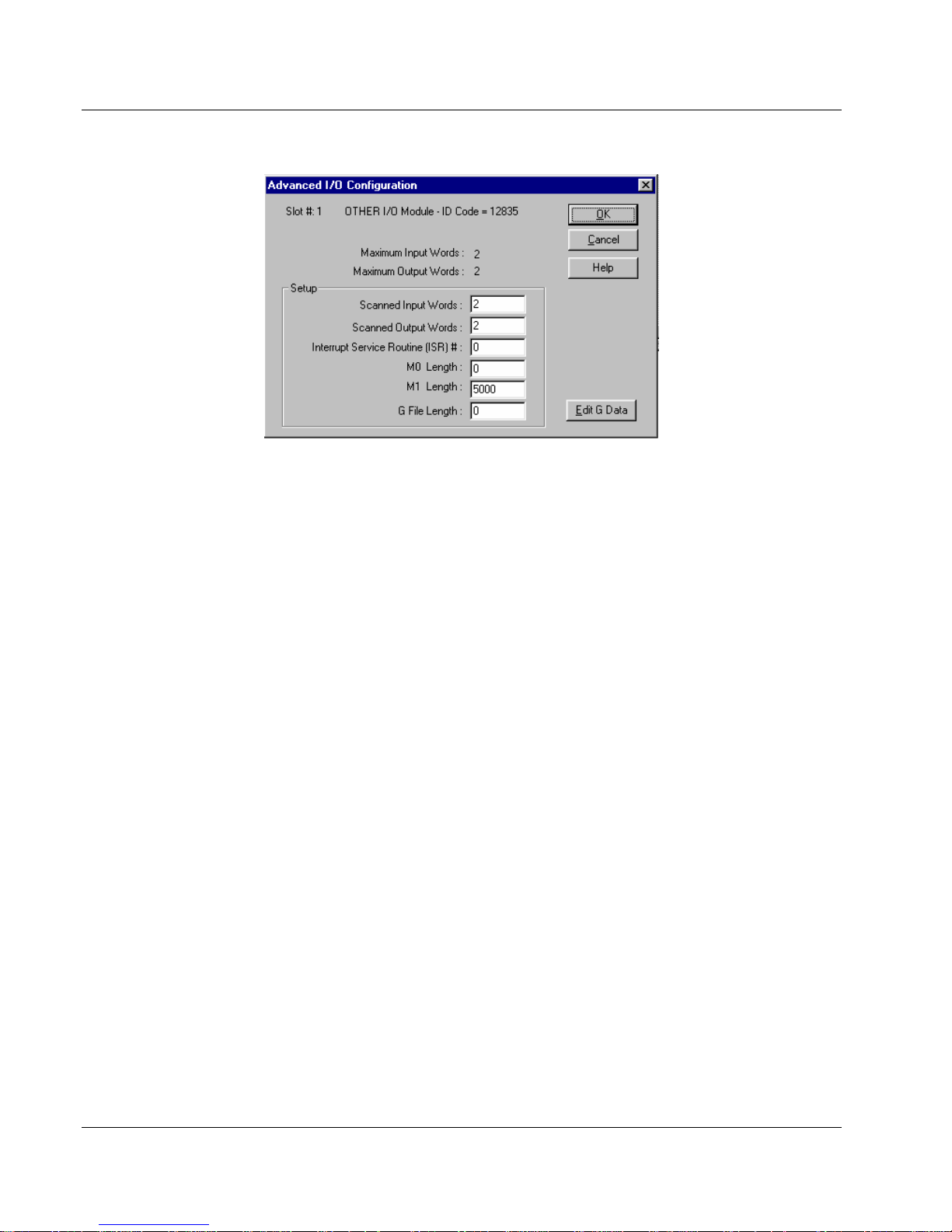
Enter the module I/O card ID number as 12835, then click OK. Double-click the
mouse on the module just added to the rack. Fill in the dialog box as shown:
The next step in the module’s setup is to define the user-defined data areas to hold
the status and read and write database areas. Edit the DFNT.CFG file now. Use any
text editor to set the values in the file. Be certain to retain the file name DFNT.CFG.
The last step in the module setup is to add the ladder logic. If the example ladder
logic is used, adjust the ladder to fit the application. When the ladder example is not
used, copy the example ladder logic to your application and alter as necessary.
The module is now ready to be used with your application. Insert the module in the
rack (with the power turned off) and attach the serial communication and network
cables. Download the new DFNT.CFG file to the module using a terminal emulation
program. Download the new application to the controller and place the processor in
run mode. If all the configuration parameters are set correctly and the module is
attached to a network, the module’s Application LED (APP LED) should remain off
and the backplane activity LED (BP ACT) should blink very rapidly. Refer to the
Diagnostics and Troubleshooting section if you encounter errors. Attach a
terminal to the Debug/Configuration port on the module and check the status of the
module using the resident debugger in the module.
3.2 Module Data
All data related to the MVI46-DFNT module is stored in user defined data files and
the module’s M1 file. Files should be defined for each data type to be used with the
module. Additionally, a file should be defined to hold the module status data. The
status data should be copied from the M1 file and placed in the assigned status file.
Input (monitor) data should be copied from the user file to the M1 file and output
(command) data should be copied from the user files to the M1 file.
Page 22 of 118 ProSoft Technology, Inc.
November 9, 2004
Page 23
Ladder Logic MVI46-DFNT ♦ SLC Platform
EtherNet/IP Interface Module
4 Ladder Logic
Ladder logic is required for application of the MVI46-DFNT module. Tasks that must
be handled by the ladder logic are data transfer, special block handling, and status
data request and receipt. This section discusses each aspect of the ladder logic as
required by the module. Additionally, a power-up handler should be written to handle
the initialization of the module’s data and to clear any processor fault conditions.
Note: The sample ladder logic periodically copies the status data from the MVI46DFNT to the SLC memory. If you don’t need to copy status data in this manner, you
might consider not using specific rungs in the sample ladder.
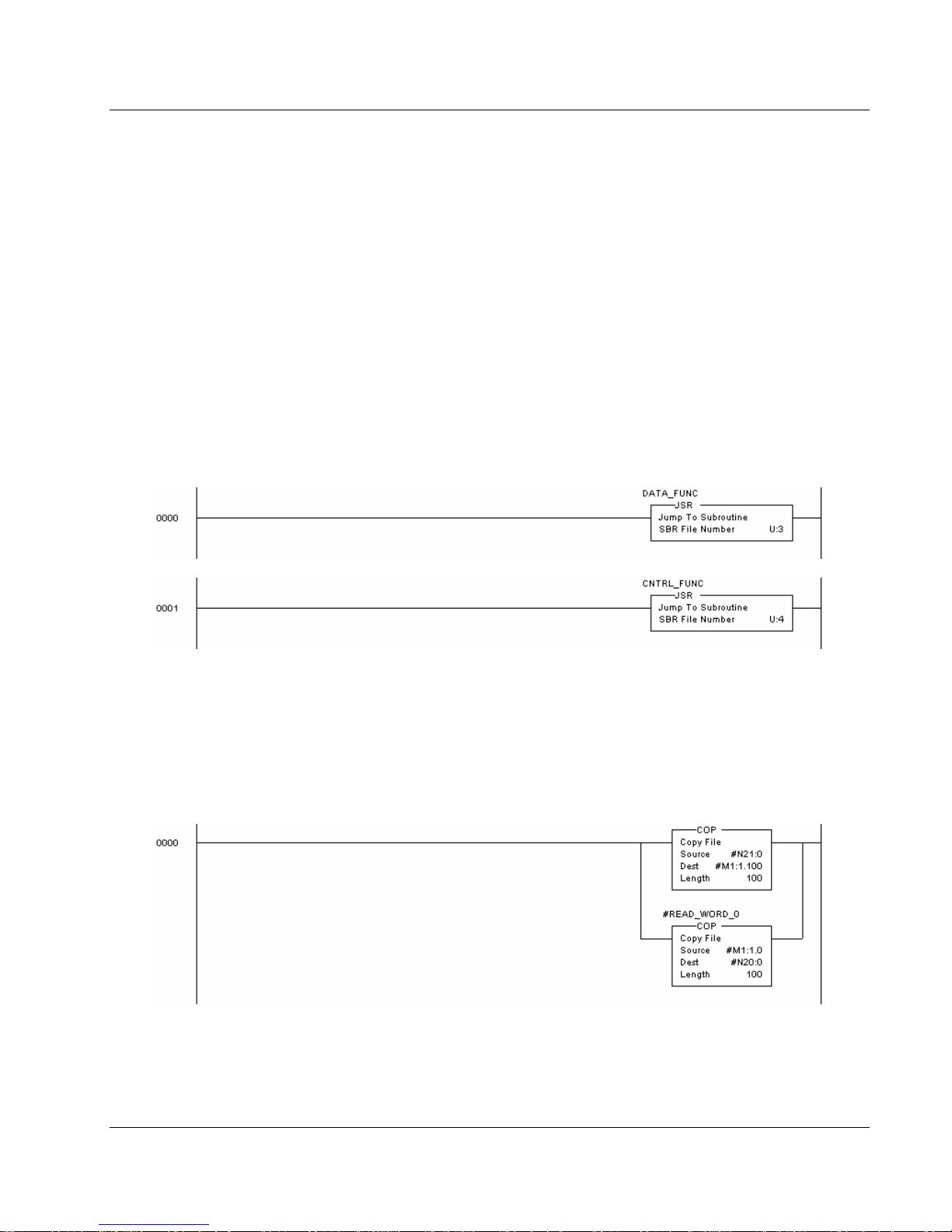
4.1 Main Routine (U:2)
The Main program file is used to call the data transfer and control subroutines. The
following example shows the main routine.
4.2 Data Transfer (U:3)
The data transfer routine is responsible for placing all the input data into the M1 file
and for retrieving all the output data from the M1 file. The rung shown in the following
diagram transfers the data between the M1 file and the user data files. The first
branch is used to transfer input data from the user file to the M1 file. The second
branch is used to transfer the output from the M1 file into the user data file.
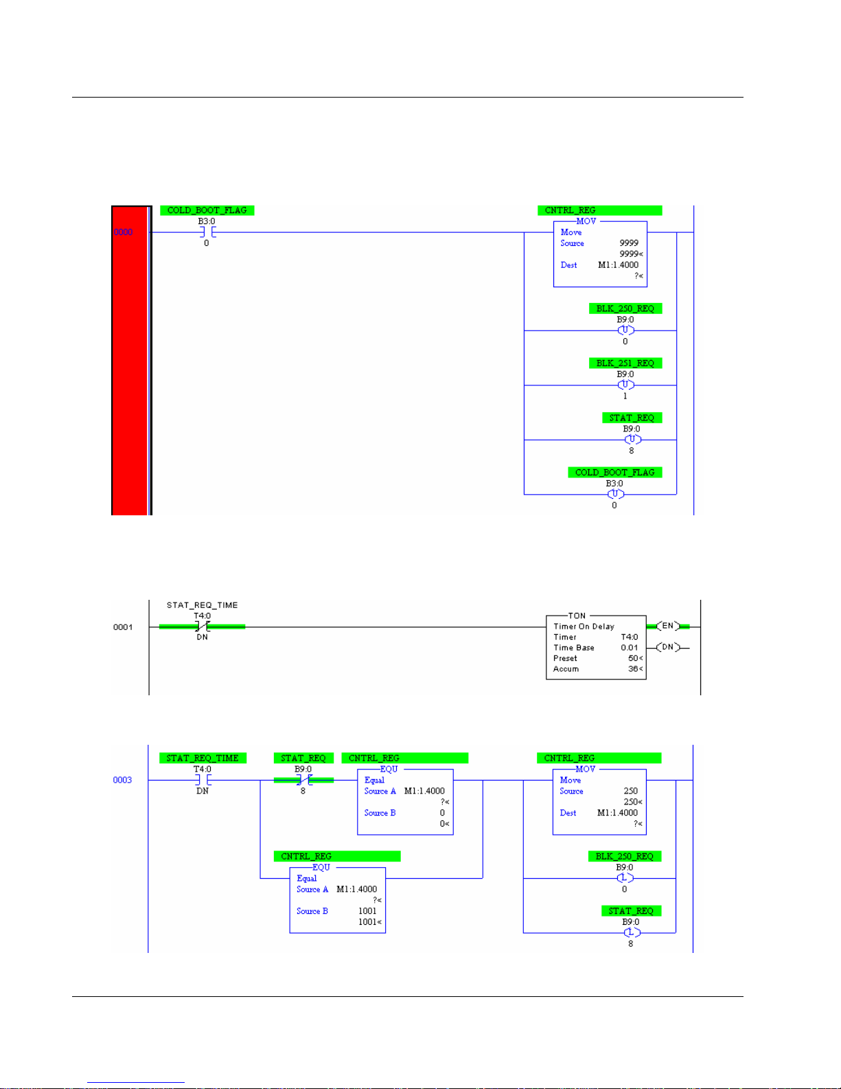
4.3 Control Routine (U:4)
The control routine is responsible for controlling the module or handling requests
from the module using the control register (M1:1.4000).
ProSoft Technology, Inc. Page 23 of 118
November 9, 2004
Page 24
MVI46-DFNT ♦ SLC Platform Ladder Logic
EtherNet/IP Interface Module
The following rung is used to request the cold boot operation for the module. Placing
the value 9999 in the control register makes this request. When the module
recognizes this value in the control register, it performs the cold boot operation. The
B9 bits are unlatched as part of the logic to keep reading status data periodically.
You don’t need this bit if you don’t intend to read status data from the module.
The next rung is used to periodically request the error/status data and command
error list data from the module. Timer T4:0 is used to trigger the requests. The
following rung is used to drive the timer:
When the timer expires, the following rung is executed:
Page 24 of 118 ProSoft Technology, Inc.
November 9, 2004
Page 25
Ladder Logic MVI46-DFNT ♦ SLC Platform
EtherNet/IP Interface Module
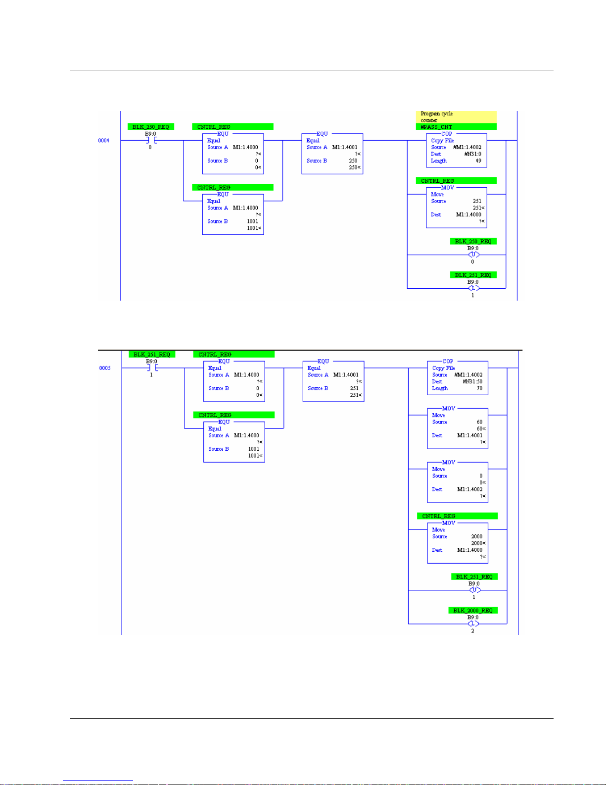
This rung is used to request a status block 250 from the module. When the module
finishes building the response block, the following rung is executed:
This rung copies the received status data into the user file and requests a status 251
block. After the module builds the response block, the following rung executes:
This rung copies the received status data into the user file and requests command
error list data for the first 60 commands in the command list. After the module builds
the data area, the following rung executes:
ProSoft Technology, Inc. Page 25 of 118
November 9, 2004
Page 26
MVI46-DFNT ♦ SLC Platform Ladder Logic
EtherNet/IP Interface Module
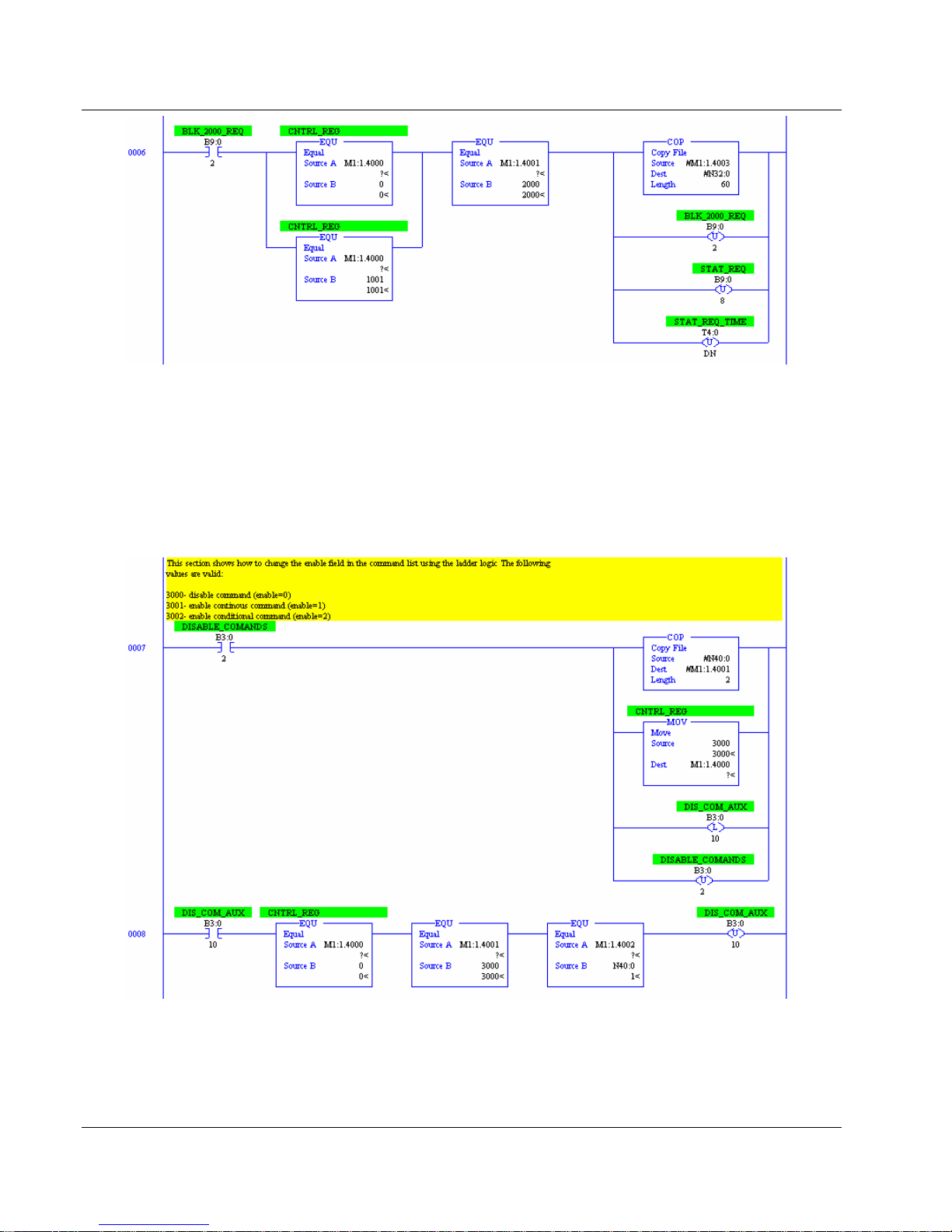
This rung copies the 60 error status values into a user file and resets the request
timer so it can trigger again.
The following rung shows how to disable commands that are enabled in the
command list using Block 3000. In this example, we use N40:0 to fill the block
structure where:
N40:0 = 1 (number of commands to be disabled)
N40:1 = 0 (start command index)
The same logic can be used for Block 3001 (enable continuous commands) and
3002 (enable conditional commands).
If the module is configured to receive the processor data set on startup, the following
rung is required:
Page 26 of 118 ProSoft Technology, Inc.
November 9, 2004
Page 27

Ladder Logic MVI46-DFNT ♦ SLC Platform
EtherNet/IP Interface Module
This feature initializes the output data in the module with the values currently held in
the processor. This feature is employed to bring the output data to a known or last
set state. This rung should be placed in a routine that will be called on every scan of
the ladder logic to ensure that the restart condition is recognized.
Important: During startup, the register M1:1.4000 contains the value 1001 after it is
set by the ladder logic.
ProSoft Technology, Inc. Page 27 of 118
November 9, 2004
Page 28

MVI46-DFNT ♦ SLC Platform Ladder Logic
EtherNet/IP Interface Module
Page 28 of 118 ProSoft Technology, Inc.
November 9, 2004
Page 29

Configuration File MVI46-DFNT ♦ SLC Platform
EtherNet/IP Interface Module
5 Configuration File
In order for the module to operate, a configuration file (DFNT.CFG) is required. This
configuration file contains information to set the data transfer characteristics between
the module and the processor, to configure the module’s client and command list,
and to configure the pass-through features. Each parameter in the file must be set
carefully in order for the application to be implemented successfully. Before editing
the file, design your system using the forms located in the appendix of this
document. Appendix B contains a configuration form to be used to construct the
DFNT.CFG file. Appendix C contains an example listing of a DFNT.CFG file.
The text file is separated into six sections with topic header names enclosed in the [ ]
characters. The sections present in the file are as follows:
[Section] Description
[Module] General module configuration information
[DFNT Client 0] Configuration for the DFNT client
[DFNT Client 0 Commands] Command list for the DFNT client
DF1 Pass-Through Server Port 1]
[DF1 Pass-Through Port]
Parameters for the pass-through port of the send port on the
module
Parameters for the DF1 port emulated on the third port of the
module
After each section header, the file contains a set of parameters. Unique labels are
used under each section to specify a parameter. Each label in the file must be
entered exactly as shown in the file for the parameter to be identified by the program.
If the module is not considering a parameter, check the label for the data item. Each
parameter's value is separated from the label with the ':' character. This character is
used by the program to delimit the position in the data record where to start reading
data. All data for a parameter must be placed after the ':' character. For numeric
parameter values any text located after the value will not be used. There must be at
least one space character between the end of the parameter value and the following
text. The following example shows a valid parameter entry:
Baud Rate : 19200 #Sets port baud rate to 19200
The parameter label is "Baud Rate" and the parameter value is 19200. The
characters after the parameter value are ignored and are used for internal
documentation of the configuration file.
Any record that begins with the '#' character is considered to be a comment record.
These records can be placed anywhere in the file as long as the '#' character is
found in the first column of the line. These lines are ignored in the file and can be
used to provide documentation within the configuration file. Liberal use of comments
within the file can ease the use and interpretation of the data in the file.
The client command list and e-mail definition sections are formatted differently than
the other sections. These sections contain lists of parameters to be used. Each list
ProSoft Technology, Inc. Page 29 of 118
November 9, 2004
Page 30

MVI46-DFNT ♦ SLC Platform Configuration File
EtherNet/IP Interface Module
begins with the label START and when the END label is reached. When entering the
records into the list, make certain that the first character in each line is left blank.
The [DFNT CLIENT 0 COMMANDS] section is used to define the EtherNet/IP
commands to be issued from the module to server devices on the network. These
commands can be used for data collection and/or control of devices on the TCP/IP
network.
5.1 Command List Overview
In order to interface the module with EtherNet/IP Server devices, the user must
construct a command list of up to 100 user-defined commands. The commands in
the list specify the server device to be addressed, the function to be performed (read
or write), the data area in the device to interface with, and the registers in the internal
database to be associated with the device data. The command list is processed from
top (command #0) to bottom. A poll interval parameter is associated with each
command to specify a minimum delay time in tenths of a second between the
issuance of a command. If the user specifies a value of 10 for the parameter, the
command is executed no more frequently than every (1) second.
Write commands have a special feature, as they can be set to execute only if the
data in the write command changes. If the register data values in the command have
not changed since the command was last issued, the command will not be executed.
If the data in the command has changed since the command was last issued, the
command is executed. Use of this feature can lighten the load on the network. In
order to implement this feature; set the enable code for the command to a value of 2.
The module supports numerous commands. This permits the module to interface
with a wide variety of devices. This includes ControlLogix, PLC5, and SLC-5/05
processors.
5.2 Commands Supported by the Module
The format of each command in the list is dependent on the function being executed.
To simplify command construction, the module uses its own set of function codes to
associate a command with a DF1 command/function type. The tables below list the
functions supported by the module:
Basic Command Set Functions
DFNT Function Code Definition Command Function
1 Protected Write 0x00 N/A
2 Unprotected Read 0x01 N/A
3 Protected Bit Write 0x02 N/A
4 Unprotected Bit Write 0x05 N/A
5 Unprotected Write 0x08 N/A
Page 30 of 118 ProSoft Technology, Inc.
November 9, 2004
Page 31

Configuration File MVI46-DFNT ♦ SLC Platform
EtherNet/IP Interface Module
PLC-5 Command Set Functions
DFNT
Function Code
100 Word Range Write(Binary Address) 0x0F 0x00
101 Word Range Read(Binary Address) 0x0F 0x01
102 Read-Modify-Write(Binary Address) 0x0F 0x26
150 Word Range Write(ASCII Address) 0x0F 0x00
151 Word Range Read(ASCII Address) 0x0F 0x01
152 Read-Modify-Write(ASCII Address) 0x0F 0x26
Definition Command Function
SLC-500 Command Set Functions
DFNT
Function Code
501
502
509
510
511
Definition Command Function
Protected Typed Logical Read w/ Two Address
Fields
Protected Typed Logic Read w/ Three Address
Fields
Protected Typed Logical Write w/ Two Address
Fields
Protected Typed Logical Write w/ Three Address
Fields
Protected Typed Logical Write w/ Mask (Three
Address Fields)
0x0F 0xA1
0x0F 0xA2
0x0F 0xA9
0x0F 0xAA
0x0F 0xAB
Each command list record has the same general format. The first part of the record
contains the information relating to the communication module and the second part
contains information required to interface to the EtherNet/IP Server device.
5.3 Command Entry Formats
The format of each command in the list is dependent on the function being executed.
Refer to the Appendix for a complete discussion of the commands supported by the
module and of the structure and content of each command.
The following table shows the structure of the configuration data necessary for each
of the supported commands:
Appendix Reference
ProSoft Technology, Inc. Page 31 of 118
November 9, 2004
Page 32

MVI46-DFNT ♦ SLC Platform Configuration File
A
r
r
r
r
r
r
r
r
r
r
r
r
r
r
r
r
r
EtherNet/IP Interface Module
DFNT COMMAND STRUCTURE
Column # 1 2 3 4 5 6 7 8 9 10 11 12
Function Enable Internal Poll Interval Swap IP Slot Function
Code Code Address Time Count Code
FC 1 Code Registe
FC 2 Code Registe
FC 3 Code Registe
FC 4 Code Registe
FC 5 Code Registe
FC 100 Code Registe
FC 101 Code Registe
FC 102 Code Registe
FC 150 Code Registe
FC 151 Code Registe
FC 152 Code Registe
FC 501 Code Registe
FC 502 Code Registe
FC 509 Code Registe
FC 510 Code Registe
FC 511 Code Registe
IP Address = IP address of pr ocessor to reach
Slot Number = -1 for PLC5 & SLC, proces sor slot number of ControlLogi x 5550
Module Information Data Device Information Data
1/10 Secs C ount Code Node Slot 1 W ord Address
1/10 Secs C ount Code Node Slot 2 W ord Address
1/10 Secs Count 0 Node Slot 3 Word Address
1/10 Secs Count 0 Node Slot 4 Word Address
1/10 Secs C ount Code Node Slot 5 W ord Address
1/10 Secs C ount Code No de Slot 100 File NumberElement Sub-Element
1/10 Secs C ount Code No de Slot 101 File NumberElement Sub-Element
1/10 Secs Count 0 Node Slot 102 File NumberElement Sub-Element
1/10 Secs C ount Code Node Slot 150 File String
1/10 Secs C ount Code Node Slot 151 File String
1/10 Secs C ount 0 Node Slot 152 File String
1/10 Secs C ount Code No de Slot 501 File Type File NumberElement
1/10 Secs C ount Code No de Slot 502 File Type File NumberElement Sub-Element
1/10 Secs C ount Code No de Slot 509 File Type File NumberElement
1/10 Secs C ount Code No de Slot 510 File Type File NumberElement Sub-Element
1/10 Secs Co unt 0 Node Slot 511 File Type File NumberElement Sub-Element
ddress Numbe
Code Function Parameters
The first part of the record is the Module Information, which relates to the module.
The second part contains information required to interface to the Server device. An
example of a command list section of the configuration file is shown in the following
figure:
[DFNT Client 0 Commands]
#
# The file contains examples for a ControlLogix processor with the N7 file
# configured. This example uses SLC and PLC5 commands.
#
# 1 2 3 4 5 6 7 8 9 10 11 12
# DB Poll Swap Func File File Elm Sub
#Enab Addr Delay Count Code Node IP Address Slot Code Type # # Elm
START
1 0 0 10 0 192.168.0.122 0 502 N 7 0 0
1 10 0 10 0 192.168.0.122 0 501 N 7 10
1 10 0 10 0 192.168.0.122 0 509 N 7 20
#
# DB Poll Swap Func File Elm Sub
#Enab Addr Delay Count Code Node IP Address Slot Code # # Elm
1 20 0 10 0 192.168.0.122 0 101 7 30 -1
1 20 0 10 0 192.168.0.122 0 100 7 40 -1
END
Page 32 of 118 ProSoft Technology, Inc.
November 9, 2004
Page 33

Configuration File MVI46-DFNT ♦ SLC Platform
EtherNet/IP Interface Module
The following table describes each parameter:
Command
Parameter
Enable 0, 1, 2
Internal
Address
Poll Delay 0 to 65535
Count
Swap Code 0,1,2,3
Range Description
0 to 3999
Command
dependent. See
Appendix for
details
This field is used to define whether or not the command is to be
executed and under what conditions.
Value Description
0
1
2
This field specifies the database address in the module’s internal
database to be associated with the command. If the command is a
read function, the data received in the response message is placed
at the specified location. If the command is write function, data used
in the command is sourced from the specified data area.
This parameter specifies the minimum interval to execute
continuous commands (Enable code of 1). The parameter is
entered in 1/10
for a command, the command executes no more frequently than
every 10 seconds.
This parameter specifies the number of registers or digital points to
be associated with the command.
This parameter is used to define if the data received from the Server
is to be ordered differently than that received from the Server
device. This parameter is helpful when dealing with floating-point or
other multi-register values, as there is no standard method of
storage of these data types in Server devices. This parameter can
be set to order the register data received in an order useful by other
applications. The following table defines the values and their
associated operations:
Swap
Code
0 None – No Change is made in the byte ordering
1 Words – The words are swapped
2
3 Bytes – The bytes in each word are swapped
The words should be swapped only when using an even number of
words.
The command is disabled and will not be
executed in the normal polling sequence.
The command is executed each scan of the
command list if the Poll Interval Time is set to
zero. If the Poll Interval time is set, the
command is executed when the interval timer
expires.
The command executes only if the internal
data associated with the command changes.
This value is valid for write commands only.
th
of a second. Therefore, if a value of 100 is entered
Description
Words & Bytes – The words are swapped then
the bytes in each word are swapped
ProSoft Technology, Inc. Page 33 of 118
November 9, 2004
Page 34

MVI46-DFNT ♦ SLC Platform Configuration File
EtherNet/IP Interface Module
Command
Parameter
Node IP
Address
Slot
Function Code See Appendix
Function
Parameters
Range Description
xxx.xxx.xxx.xxx The IP address of the device being addressed by the command.
See Appendix
Use a value of –1 when interfacing to an SLC 5/05 or a PLC5.
These devices do not have a slot parameter. When addressing a
ControlLogix processor, the slot number corresponds to the slot in
the rack containing the controller being addressed. In the
ControlLogix platform, the controller can be placed in any slot and
the rack may contain multiple processors. This parameter uniquely
selects a controller in the rack.
These parameters specify the function to be executed by the
command. The Appendix in this manual describes the meaning of
these values for each of the available supported commands.
Following is a complete list of the command supported by the Client
driver.
Function Code Listing
Basic Command Set
1 Protected Write
2 Unprotected Read
3 Protected Bit Write
4 Unprotected Bit Write
5 Unprotected Write
PLC-5 Command Set (0x0F)
100 Word Range Write (Binary Address)
101 Word Range Read (Binary Address)
102 Read-Modify-Write (Binary Address)
150 Word Range Write (ASCII Address)
151 Word Range Read (ASCII Address)
152 Read-Modify-Write (ASCII Address)
SLC Command Set (0x0F)
501 Prot Typed Read w/ 2 addr fields
502 Prot Typed Read w/ 3 addr fields
509 Prot Typed Write w/ 2 addr fields
510 Prot Typed Write w/ 3 addr fields
511 Prot Type Write w/ Mask 3 addr fields
The number of auxiliary parameters required is dependent on the
function code selected for the command. Refer to the appendix for a
complete list of parameters and their definition required for each
function.
Page 34 of 118 ProSoft Technology, Inc.
November 9, 2004
Page 35

Diagnostics and Troubleshooting MVI46-DFNT ♦ SLC Platform
EtherNet/IP Interface Module
6 Diagnostics and Troubleshooting
This section provides information on diagnostics and troubleshooting in three forms:
• Status data values are transferred from the module to the controller under
ladder logic control using the command control data area in the M1 file.
• All data contained in the module can be viewed through the
Configuration/Debug port attached to a terminal emulator.
• LED status indicators on the front of the module provide information on the
modules status.
6.1 Reading Status Data From the Module
The MVI46-DFNT module returns two status data blocks that can be used to
determine the module’s operating status. This data is requested by the ladder logic
and returned in the module’s M1 file. This data can also be viewed using the
Configuration/Debug port with a terminal emulation program. The
Configuration/Debug port provides the following functionality:
• Full view of the module's configuration data
• View of the module's status data
• Complete display of the module's internal database (registers 0 to 3999)
• Version Information
• Control over the module (warm boot, cold boot)
• Facility to upload and download the module's configuration file
6.1.1 Required Hardware
The hardware requirements to interface with the configuration/debugger port are not
too stringent. A personal computer with a standard serial port should suffice. For
optimal performance, the minimum is required:
• 80486 based processor (Pentium preferred)
• 1 megabyte of memory
• At least one serial communications port available
Additionally, a null-modem cable is required between your PC and the port. The
module's port has a DB-9 male connector at the end of a RJ-45 to DB-9 pigtail. The
RJ-45 end of the cable is to be placed in the MVI46-DFNT port 1 connector (top
port). The cable required is displayed in the following diagram:
MVI46-DFNT Configuration/Debug Port Cable
DB-9 Male
RxD
TxD
COM
RS-232 Host
2
3
5
TxD
RxD
COM
ProSoft Technology, Inc. Page 35 of 118
November 9, 2004
Page 36

MVI46-DFNT ♦ SLC Platform Diagnostics and Troubleshooting
EtherNet/IP Interface Module
6.1.2 Required Software
The software required on your personal computer to interface with the
configuration/debugger port is operating system dependent. Tested software
includes the following:
DOS ProComm, PS-Term and several other terminal emulation programs
Windows 3.1 Terminal
Windows 95/98 HyperTerminal and PS-Term
Windows NT / 2000 / XP HyperTerminal
Linux Minicom
Any ASCII terminal emulation software package provided with your operating system
should work as long as it can be configured as follows:
Baud Rate 57,600
Parity None
Data Bits 8
Stop Bits 1
Software Handshaking XON/XOFF
6.1.3 Using the Port
The following steps are required to interface with the configuration/debugger port:
1. Connect your computer to the module's port using a Null Modem cable.
2. Start the terminal emulation program on your computer and configure the
communication parameters.
3. Enter the "?" character on your computer. If the system is set up properly, the
port's menu is displayed.
The DFNT Communication Module Menu appears and contains options that allow
the viewing of various types of information.
6.1.4 Menu Options
Features available through the use of the configuration/debug port on the MVI46DFNT module are all accessed using single keystrokes on your computer. There is a
single main menu and several sub-menus presented on the port. To view the current
selections available, press the '?' key on your computer. If you are in main menu
mode, the following menu appears:
Page 36 of 118 ProSoft Technology, Inc.
November 9, 2004
Page 37

Diagnostics and Troubleshooting MVI46-DFNT ♦ SLC Platform
EtherNet/IP Interface Module
If this menu is not shown, press the 'M' key to display the main menu. All facilities
offered by the configuration/debugger are shown on the main menu. Each option is
discussed in the following sections.
6.1.4.1 B = Block Transfer Statistics
This menu option displays the configuration and statistics of the backplane data
transfer operations. After selecting this option, the following is displayed. Selecting
this option at one-second intervals can be used to determine the number of blocks
transferred each second.
6.1.4.2 C = Module Configuration
This option displays the general module configuration information for the MVI46DFNT module. After selecting the option, the following screen appears:
6.1.4.3 D = Database View
This menu option places the program in database view menu mode. This mode of
operation is used to display the module's internal database values. To view the menu
options available in this mode, press the '?' key and the following menu appears:
ProSoft Technology, Inc. Page 37 of 118
November 9, 2004
Page 38

MVI46-DFNT ♦ SLC Platform Diagnostics and Troubleshooting
EtherNet/IP Interface Module
All data contained in the module's database is available for viewing using the menu
options. Each option available on the menu is discussed in the following sections.
0-3 = Register pages 0-3000
This menu option jumps to a specific set of registers in the database and displays the
data. The keys perform the following functions:
Key FUNCTION
0 Display registers 0 to 99
1 Display registers 1000 to 1099
2 Display registers 2000 to 2099
3 Display registers 3000 to 3099
S = Show Again
This menu option displays the current page of 100 registers in the database.
Example output of the database display is shown:
- = Back 5 Pages
This menu option skips the previous 500 registers of data for viewing and displays
the data.
P = Previous Page
This menu option selects and displays the previous 100 registers of data.
+ = Skip 5 Pages
This menu option skips 500 registers of data and displays the new page of data.
N = Next Page
This menu option selects the next 100 registers of data for viewing and displays the
data.
Page 38 of 118 ProSoft Technology, Inc.
November 9, 2004
Page 39

Diagnostics and Troubleshooting MVI46-DFNT ♦ SLC Platform
EtherNet/IP Interface Module
D = Decimal Display
This menu option displays the data on the current page in decimal format.
H = Hexadecimal Display
This menu option displays the data on the current page in hexadecimal format.
F = Float Display
This menu option displays the data on the current page in floating-point format. The
program assumes that the values are aligned on even register boundaries. If floatingpoint values are not aligned as such, they are not displayed properly.
A = ASCII Display
This menu option displays the data on the current page in ASCII format. This is
useful for regions of the database that contain ASCII data.
M = Main Menu
This menu option returns to the main menu mode.
6.1.4.4 E = Client 0 Command Errors
This menu selection is used to view the error code associated with each command in
the command list for the client. This mode of operation is used to display multiple
pages of command list error/status data. To view the menu options available in this
mode, press the '?' key and the following menu will be displayed:
Each menu option is discussed in the following sections.
S = Show Again
This option displays the current page of master command error/status data. After
selecting the option, the following screen appears.
Each value shown on the screen corresponds to the error/status code for the
associated master command list index.
- = Back 2 Pages
This option skips back 20 commands and displays the data.
P = Previous Page
This option displays the previous page of data.
+ = Skip 2 Pages
This option skips past the next 20 commands and displays the data.
ProSoft Technology, Inc. Page 39 of 118
November 9, 2004
Page 40

MVI46-DFNT ♦ SLC Platform Diagnostics and Troubleshooting
EtherNet/IP Interface Module
N = Next Page
This option displays the next page of master command list error/status data.
D = Decimal Display
This option changes the display of the data to decimal format.
H = Hexadecimal Display
This option changes the display of error/status data to hexadecimal format.
M = Main Menu
This option returns the program to main menu mode.
6.1.4.5 I = Client 0 Command List
This menu selection is used to view the commands for the client in the module. This
mode of operation is used to display multiple pages of master command list data. To
view the menu options available in this mode, press the '?' key and the following
menu appears:
Each option on the menu is discussed in the following sections:
S = Show Again
This option displays the current page of master commands. Ten commands are
displayed on each page as shown:
If an enabled command has an error, the EN field will contain a value of –1. This
means that the command will be re-issued every 30 seconds.
- = Back 5 Pages
This menu option displays the master command list data after skipping the previous
50 commands.
P = Previous Page
This menu option displays the previous page of master command list data.
+ = Skip 5 Pages
This menu option displays the master command list data after skipping the next 50
commands.
Page 40 of 118 ProSoft Technology, Inc.
November 9, 2004
Page 41

Diagnostics and Troubleshooting MVI46-DFNT ♦ SLC Platform
EtherNet/IP Interface Module
N = Next Page
This menu option displays the next page of master command list data.
M = Main Menu
This option returns to the main menu mode of operation.
6.1.4.6 R = Transfer Configuration from PC to MVI Unit
This option receives the configuration file from a remote PC and places the file on
the module’s Compact Flash Disk. The name of the file is fixed in the program –
DFNT.CFG. All other file names are ignored by the program. After selecting the
option, press the ‘Y’ key to confirm the action. Follow the instructions displayed on
the terminal to complete the download process. After the file is successfully
downloaded, the module restarts the program and uses the new configuration
information. Examine the new configuration using menu options ‘C’, ‘I’, and the
database options to ensure that the module is configured properly.
6.1.4.7 S = Transfer Configuration from MVI Unit to PC
This option sends the configuration file contained in the module to a remote PC. After
selecting the option, press the ‘Y’ key to confirm the action. Then, follow the
instructions presented on the terminal. After the send operation is complete, the file
will reside on your PC.
6.1.4.8 T = Display e-mail setup
This option displays the e-mail set up information for the module. This information is
used to generate the user specified e-mail messages based on changes in the
module’s database. After selecting the option, the following screen appears:
6.1.4.9 U = Reset diagnostic data
This option resets the block status data.
6.1.4.10 V = Version Information
This option is used to view the current version of the software for the module and
other important values. After selecting the option, the following appears:
ProSoft Technology, Inc. Page 41 of 118
November 9, 2004
Page 42

MVI46-DFNT ♦ SLC Platform Diagnostics and Troubleshooting
EtherNet/IP Interface Module
This information may be requested when calling for technical support on the product.
Values at the bottom of the display are important in determining module operation.
The Program Scan Counter value is incremented each time a module's program
cycle is complete. This value can be used to determine the frequency of program
execution by pressing the 'V' key at one-second intervals.
6.1.4.11 W = Warm Boot Module
This option is selected when a warm-boot operation is required of the module. In this
version of the software, the module completely restarts the program on a warm-boot
request.
6.1.4.12 1 = Network & Clients
This option displays the statistics of the network and the DFNT client. After selecting
the option, the following information appears:
6.1.4.13 2- 5 = DFNT Servers
This option is used to view the status data for the DFNT servers. After selecting the
“2” option, the following appears:
6.1.4.14 3 = DF1 Server
This option is used to view the status data for the DFNT pass-through server. After
selecting the option, the following information appears:
Page 42 of 118 ProSoft Technology, Inc.
November 9, 2004
Page 43

Diagnostics and Troubleshooting MVI46-DFNT ♦ SLC Platform
EtherNet/IP Interface Module
6.1.4.15 5 = Client Configuration
This option is used to view the client configuration data. After selecting the option,
the following information appears:
6.1.4.16 6 = DF1 Server Configuration
This option displays the configuration information for the DF1 pass-through server.
After selecting the option, the following information appears:
6.1.4.17 0 = DF1 PT Port
This option displays the configuration information for the DF1 pass-through port.
After selecting the option, the following information appears:
6.1.4.18 @ = Network Menu
This option is used to reach the network file transfer and viewing menu. Options on
this menu interface with the WATTCP.CFG file that contains the IP, gateway, and
other network specification information. After selecting the menu option, press the ‘?’
key to display the following menu:
Each menu option is discussed in the following sections.
R = Receive WATTCP.CFG
This option transfers a new WATTCP.CFG file from the remote PC to the module.
This option is required in order to change any of the network configuration file
information (i.e., module’s IP address). After selecting the option, follow the
instructions given to transfer the file.
S = Send WATTCP.CFG
This option transfers the WATTCP.CFG file contained in the module to a remote PC.
This facility is useful in order to retrieve the network configuration file of the module
when the archive for the module is not available. After selecting the option, follow the
instructions given to transfer the file.
ProSoft Technology, Inc. Page 43 of 118
November 9, 2004
Page 44

MVI46-DFNT ♦ SLC Platform Diagnostics and Troubleshooting
EtherNet/IP Interface Module
V = View WATTCP.CFG
This option displays the contents of the WATTCP.CFG file. After selecting the option,
the following information appears:
M = Main Menu
This option is used to return to the main program menu.
6.1.4.19 Esc = Exit Program
This option exits the program and displays the operating system prompt. This option
should only be selected if instructed by the ProSoft Technical Support Group. If you
select the option, the module will cease operation. Data will no longer be transferred
between on the Ethernet network and the module and between the SLC processor
and the module. This might cause an upset to a currently running process.
6.2 LED Status Indicators
The LED's indicate the module’s operating status as follows:
ProSoft
Module
P1 Green
P2 Green
P3 Green
BP ACT Amber
OK
Color Status Indication
On
Off No data is being transferred on the Configuration/Debug port.
On
Off No data is being transferred on this port
On
Off No data is being transferred on this port
Off The MVI46-DFNT is working normally. APP Amber
On The MVI46-DFNT module program has recognized an error.
On
Off
Red/
Green
Off
Data is being transferred between the module and a remote
terminal using the Configuration/Debug port.
Data is being transferred between the module and the
processors Channel 0 port.
Data is being transferred on this port and the remote device
connected to the port
The LED is on when the module is performing a write operation
on the backplane.
The LED is off when the module is performing a read operation
on the backplane. Under normal operation, the LED should
blink rapidly on and off.
The card is not receiving any power and is not securely
plugged into the rack.
Page 44 of 118 ProSoft Technology, Inc.
November 9, 2004
Page 45

Diagnostics and Troubleshooting MVI46-DFNT ♦ SLC Platform
V
V
y
)
y
EtherNet/IP Interface Module
ProSoft
Color Status Indication
Module
Green The module is operating normally.
Red
The program has detected an error or is being configured. If the
LED remains red for over 10 seconds, the program has
probably halted. Remove the card from the rack and re-insert
the card to restart the module's program.
Off The battery voltage is OK and functioning. BAT Red
On
The battery voltage is low or the battery is not present. Replace
the battery on the module.
If a configuration error is found for the client, the client configuration error word will
have a value other than zero. The configuration error word bits have the following
definitions:
Bit Description
0 0x0001
1 0x0002
2 0x0004
3 0x0008
4 Invalid retry count (0 to 10) 0x0010
5 0x0020
6 0x0040
7 0x0080
8 0x0100
9 0x0200
10 0x0400
11 0x0800
12 0x1000
13 0x2000
14 0x4000
15 0x8000
alue
If a configuration error is present for the pass-through server, the configuration error
word contains a value other than zero. The configuration error word bits have the
following definitions:
Bit Description
0 Invalid enable code 0x0001
1 Invalid bus
2 0x0004
3 0x0008
4 0x0010
5 Invalid baud rate 0x0020
6 Invalid parit
7 Invalid data bits 0x0080
8 Invalid stop bits 0x0100
9 0x0200
10 0x0400
11 0x0800
12 0x1000
13 0x2000
14 0x4000
15 0x8000
timeout setting (<100 mSec
alue
0x0002
0x0040
If a configuration error is present for the pass-through port, the configuration error
word contains a value other than zero. The configuration error word bits have the
following definitions:
ProSoft Technology, Inc. Page 45 of 118
November 9, 2004
Page 46

MVI46-DFNT ♦ SLC Platform Diagnostics and Troubleshooting
V
y
EtherNet/IP Interface Module
Bit Description
0 Invalid enable code 0x0001
1 Invalid local station ID 0x0002
2 Invalid protocol or termination type 0x0004
3 Invalid baud rate 0x0008
4 Invalid parit
5 Invalid data bits 0x0020
6 Invalid stop bits 0x0040
7 0x0080
8 Invalid Use CTS Line selection 0x0100
9 Invalid retry count 0x0200
10 0x0400
11 0x0800
12 0x1000
13 0x2000
14 0x4000
15 0x8000
Correct any invalid data in the configuration for proper module operation. When the
configuration contains a valid parameter set, all the bits in the configuration words
are clear. This does not indicate that the configuration is valid for the user
application. Make sure each parameter is set correctly for the specific application.
If the APP, BP ACT and OK LED’s blink at a rate of every one-second, call ProSoft
Technology, Inc. support. There is a serious problem with the module, and it will
have to be sent back to ProSoft.
6.2.1 Clearing a Fault Condition
Typically, if the OK LED on the front of the module becomes illuminated red for over
ten seconds, a hardware problem has been detected in the module or the program
has exited. To attempt to clear the condition:
1. Turn the power to the rack off
2. Remove the card from the rack
3. Make certain the Compact Flash is installed and all jumpers are set correctly
4. Re-insert the card in the rack and turn the power back on
5. Verify the configuration data being transferred to the module from the SLC
processor
If the module’s OK LED does not turn green, make sure the module is inserted
completely into the rack. If this does not cure the problem, contact the factory.
alue
0x0010
6.2.2 Troubleshooting
In order to assist in the troubleshooting of the module, the following table has been
put together to assist you. Please use the following to help in using the module, but if
you have additional questions or problems, please do not hesitate to contact us.
The entries in this section have been placed in the order in which the problems
would most likely occur after powering up the module.
Page 46 of 118 ProSoft Technology, Inc.
November 9, 2004
Page 47

Diagnostics and Troubleshooting MVI46-DFNT ♦ SLC Platform
EtherNet/IP Interface Module
Problem Description Steps to take
Processor Fault
BP ACT LED remains off or
blinks slowly
ACT/FLT LED remains red
Be sure that the module is plugged into the slot that has been
configured for the MVI46-DFNT module.
Be sure the ladder logic has been set up correctly
This indicates that backplane transfer operations are failing. Use the
Configuration/Debug port facility to check this. To establish backplane
communications make sure of the following:
The backplane driver is loaded in the module.
The module is configured for read and write block data transfer.
The ladder logic handles all read and write block situations.
The module is configured in the processor.
The program has halted or a critical error has occurred. Connect to
the Configuration/Debug port to see if the module is running.
ProSoft Technology, Inc. Page 47 of 118
November 9, 2004
Page 48

MVI46-DFNT ♦ SLC Platform Diagnostics and Troubleshooting
EtherNet/IP Interface Module
Page 48 of 118 ProSoft Technology, Inc.
November 9, 2004
Page 49

Cable Connections MVI46-DFNT ♦ SLC Platform
EtherNet/IP Interface Module
7 Cable Connections
The MVI46-DFNT module has the following communication connections on the
module:
• One Ethernet port (RJ45 connector)
• One RS-232 Configuration/Debug port (RJ45 connector)
• Two RS-232/485/422 ports for pass-through operation
Communication
P1 P2 P3
APP BP
ACT/ BAT
FLT
Ethernet RJ- 45
Application Port
7.1 Ethernet Connection
The MVI46-DFNT module has a single RJ45 plug located on the front of the module
for use with the EtherNet/IP network. The module is connected to the Ethernet
network using a cable between the module’s RJ45 connector and a hub or switch.
Please ensure that the proper cable and hub are used with the module. Failure to
ensure proper installation of the module may cause physical damage to the module.
Check with your IT or network support group before installing the module on the
network to ensure that the module has a valid IP address for the network.
7.2 Pass-Through Ports
Two pass-through ports are provided on the module. Port 2 can be connected to the
processor’s Channel 0 port and Port 3 can be connected to a remote DF1 master
device. The cable configuration used on the ports is dependent on the RS-interface
selected for the port using the jumpers located on the MVI circuit board. The
following are port pin-outs for several configurations of the ports:
Module Configuration/
Debug Port
Programming &
Pass-through Port
Emulated
Channel 0 Port
ProSoft Technology, Inc. Page 49 of 118
November 9, 2004
Page 50

MVI46-DFNT ♦ SLC Platform Cable Connections
EtherNet/IP Interface Module
MVI46-DFNT RS-232 Interface (No Handshaking)
DB-9 Male
RxD
TxD
COM
TxD/RxD+
TxD/RxD-
GND
TxD+
TxD-
COM
RxD+
RxD-
2
3
5
MVI46-DFNT RS-232 Inte r f a ce (Use CTS Line and Modem)
DB-9 Male
2
3
5
7 RTS
8 CTS
MVI46-DFNT RS-485 I nte rface
DB-9 Male
1
8
5
MVI46-DFNT RS-422 Interface
DB-9 Male
1
8
5
2
6
RS-232 Host
TxD
RxD
COM
Modem
RxD
TxD
COM
RS-485 Device
TxD/RxD+
TxD/RxD-
GND
RS-422 Device
RxD+
RxD-
COM
TxD+
TxD-
7.3 RS-232 Configuration/Debug Port
This port is physically an RJ-45 connection (An RJ-45 to DB-9 adapter cable is
shipped with the module). This port permits a PC-based terminal emulation program
to view configuration and status data in the module and to control the module. The
cable for communications on this port is shown in the following diagram:
MVI46-DFNT Configuration/Debug Port Cable
DB-9 Male
RxD
TxD
COM
2
3
5
RS-232 Host
TxD
RxD
COM
Page 50 of 118 ProSoft Technology, Inc.
November 9, 2004
Page 51

Ethernet Port Configuration: wattcp.cfg MVI46-DFNT ♦ SLC Platform
EtherNet/IP Interface Module
8 Ethernet Port Configuration: wattcp.cfg
The wattcp.cfg file must be set up properly in order to use a TCP/IP network
connection. You can view the current network configuration using an ASCII terminal
by selecting “@” (Network Menu) and “V” (View) options when connected to the
Debug port.
# ProLinx Communication Gateways, Inc.
# Default private class 3 address
my_ip=192.168.0.100
# Default class 3 network mask
netmask=255.255.255.0
# name server 1 up to 9 may be included
# nameserver=xxx.xxx.xxx.xxx
# name server 2
# nameserver=xxx.xxx.xxx.xxx
# The gateway I wish to use
gateway=192.168.0.1
# some networks (class 2) require all three parameters
# gateway,network,subnetmask
# gateway 192.168.0.1,192.168.0.0,255.255.255.0
# The name of my network
# domainslist="mynetwork.name"
ProSoft Technology, Inc. Page 51 of 118
November 9, 2004
Page 52

MVI46-DFNT ♦ SLC Platform Ethernet Port Configuration: wattcp.cfg
EtherNet/IP Interface Module
Page 52 of 118 ProSoft Technology, Inc.
November 9, 2004
Page 53

Appendix A - MVI46-DFNT Status Data Definition MVI46-DFNT ♦ SLC Platform
y
g
g
EtherNet/IP Interface Module
Appendix A - MVI46-DFNT Status Data Definition
This appendix contains a description of the members present in the status data
blocks returned to the SLC processor under ladder logic control. The two blocks, 250
and 251, are requested and returned in the module’s M1 file in the command control
data area under ladder logic control.
The data set returned to the processor in the M1 file for a 250 request has the
following definition:
Offset Content Description
4000 Done Flag This word contains a value of 0 to indicate the
4001 Status Code This word contains the value 250
4002 Program Scan
Count
4003-4004 Product Product Name (ASCII)
4005-4006 Rev Revision (ASCII)
4007-4008 Op Sys Operating System (ASCII)
4009-4010 Run Production Run Number (ASCII)
status block is completel
This value is incremented each time a complete
program cycle occurs in the module.
built
4011 Not Used Reserved
4012 Not Used Reserved
4013 Not Used Reserved
4014 Number of
Requests
4015 Number of
Responses
4016 Not Used Reserved
4017 Not Used Reserved
4018 Not Used Reserved
4019 Not Used Reserved
4020 Not Used Reserved
4021 Client Cmd
Request
4022 Client Cmd
Response
4023 Client Cmd Error This value is incremented each time an error
4024 Client Request
Count
4025 Client Response
Count
4026 Client Error Sent
Count
4027 Client Error
Received Count
4028 Client Cfg Error
Word
4029 Client Current
Error Code
4030 Client Last Error
Code
HTTP Port 80 Status
Total number of http requests for the module
Total number of http response messages
generated.
DFNT Client 0 Status
This value is incremented each time a com mand
request is issued.
This value is incremented each time a com mand
response is received.
message is received from a remote unit or a local
error is generted for a command.
This value is incremented each time a request
messa
e is issued.
This value is incremented each time a response
messa
e is received.
This value is incremented each time an error is
sent from the client.
This value is incremented each time an error is
received from a rem ote unit.
This word contains a bit map that defines
configuration errors in the configuration file for the
client.
This value corresponds to the current error code
for the client.
This value corresponnds to the last error code
recorded for the client.
ProSoft Technology, Inc. Page 53 of 118
November 9, 2004
Page 54

MVI46-DFNT ♦ SLC Platform Appendix A - MVI46-DFNT Status Data Definition
V
EtherNet/IP Interface Module
4031 Read Block Count This field contains the total number of read blocks
4032 W rite Block Count This field contains the total number of write blocks
4033 Parse Block Count This field contains the total number of blocks
4034 Comm and Event
Block Count
4035 Comm and Block
Count
4036 Error Block Count This field contains the total number of block errors
4037 Socket State
4038 Connection State
4039 Open Count Total number of times the server has performed
4040 Establish Count Total num ber of times a connection has been
4041 Close Count Total number of times the server has performed a
4042 Read Total number of packets received by the server.
4043 Message Total number of message receive by the server.
4044 W rite Total number of packets sent from the server to
4045 Timeout Total number of times the server as reached a
4046 Host Port Service port on client connected to the server.
4047-4048 Host IP Address IP address of the client connected to the server.
Block Status
transferred from the module to the processor.
transferred from the processor to the m odule.
successfully parsed that were received from the
processor.
This field contains the total number of command
event blocks received from the processor.
This field contains the total number of command
blocks received from the processor.
recognized by the module.
Pass-Through Server Status
an open operation.
established on the server.
close operation.
the client.
connection timeout condition.
4049 PTP Cfg Error
Word
4050 PTS Cfg Error
Word
Pass-through port configuration error word.
Pass-through server configuration error word.
The format of the client configuration error word is as follows:
Bit Description
0 0x0001
1 0x0002
2 0x0004
3 0x0008
4 Invalid retry count (0 to 10) 0x0010
5 0x0020
6 0x0040
7 0x0080
8 0x0100
9 0x0200
10 0x0400
11 0x0800
12 0x1000
13 0x2000
14 0x4000
15 0x8000
alue
Page 54 of 118 ProSoft Technology, Inc.
November 9, 2004
Page 55

Appendix A - MVI46-DFNT Status Data Definition MVI46-DFNT ♦ SLC Platform
V
y
V
y
)
y
r
r
r
EtherNet/IP Interface Module
The format of the pass-through port configuration error word is as follows:
Bit Description
0 Invalid enable code 0x0001
1 Invalid local station ID 0x0002
2 Invalid protocol or termination type 0x0004
3 Invalid baud rate 0x0008
4 Invalid parit
5 Invalid data bits 0x0020
6 Invalid stop bits 0x0040
7 0x0080
8 Invalid Use CTS Line selection 0x0100
9 Invalid retry count 0x0200
10 0x0400
11 0x0800
12 0x1000
13 0x2000
14 0x4000
15 0x8000
alue
0x0010
The format of the pass-through server configuration error word is as follows:
Bit Description
0 Invalid enable code 0x0001
1 Invalid bus
2 0x0004
3 0x0008
4 0x0010
5 Invalid baud rate 0x0020
6 Invalid parit
7 Invalid data bits 0x0080
8 Invalid stop bits 0x0100
9 0x0200
10 0x0400
11 0x0800
12 0x1000
13 0x2000
14 0x4000
15 0x8000
timeout setting (<100 mSec
alue
0x0002
0x0040
The values for the pass-through server state parameter have the following definition:
State Definition
-1 Listen function called to set up serve
0 Waiting for connection to be established on serve
1 Waiting and processing data received
2 Waiting for pass-through port to be free
3 Pass-through server owns port and processes all data
received and written.
100 Closing server on program termination
1000 Initiate a close on the serve
1001 Waiting for server to successfully close
The connection state for the pass-through server is not used at this time.
ProSoft Technology, Inc. Page 55 of 118
November 9, 2004
Page 56

MVI46-DFNT ♦ SLC Platform Appendix A - MVI46-DFNT Status Data Definition
y
EtherNet/IP Interface Module
The data set returned to the processor in the M1 file for a 251 request has the
following definition:
Offset Content Description
4000 Done Flag This word contains a value of 0 to indicate the
status block is completel
4001 Status Code This word contains the value 251
DFNT Server 0 Status
4002 Socket State
4003 Connection State
4004 Open Count Total number of times the server has performed
an open operation.
4005 Establish Count Total num ber of times a connection has been
established on the server.
4006 Close Count Total number of times the server has performed a
close operation.
4007 Read Total number of packets received by the server.
4008 Message Total number of message receive by the server.
built
4009 W rite Total number of packets sent from the server to
the client.
4010 Timeout Total number of times the server as reached a
connection timeout condition.
4011 Host Port Service port on client connected to the server.
4012-4013 Host IP Address IP address of the client connected to the server.
DFNT Server 1 Status
4014 Socket State
4015 Connection State
4016 Open Count Total number of times the server has performed
an open operation.
4017 Establish Count Total number of times a connection has been
established on the server.
4018 Close Count Total number of times the server has performed a
close operation.
4019 Read Total number of packets received by the server.
4020 Message Total number of message receive by the server.
4021 Write Total number of packets sent from the server to
the client.
4022 Timeout Total number of times the server as reached a
connection timeout condition.
4023 Host Port Service port on client connected to the server.
4024-4025 Host IP Address IP address of the client connected to the server.
DFNT Server 2 Status
4026 Socket State
4027 Connection State
4028 Open Count Total number of times the server has performed
an open operation.
4029 Establish Count Total number of times a connection has been
established on the server.
4030 Close Count Total number of times the server has performed a
close operation.
4031 Read Total number of packets received by the server.
4032 Message Total number of message receive by the server.
4033 Write Total number of packets sent from the server to
4034 Timeout Total number of times the server as reached a
4035 Host Port Service port on client connected to the server.
4036-4037 Host IP Address IP address of the client connected to the server.
Page 56 of 118 ProSoft Technology, Inc.
the client.
connection timeout condition.
November 9, 2004
Page 57

Appendix A - MVI46-DFNT Status Data Definition MVI46-DFNT ♦ SLC Platform
EtherNet/IP Interface Module
4038 Socket State
DFNT Server 3 Status
4039 Connection State
4040 Open Count Total number of times the server has performed
an open operation.
4041 Establish Count Total number of times a connection has been
established on the server.
4042 Close Count Total number of times the server has performed a
close operation.
4043 Read Total number of packets received by the server.
4044 Message Total number of message receive by the server.
4045 Write Total number of packets sent from the server to
the client.
4046 Timeout Total number of times the server as reached a
connection timeout condition.
4047 Host Port Service port on client connected to the server.
4048-4049 Host IP Address IP address of the client connected to the server.
DFNT Server 4 Status
4050 Socket State
4051 Connection State
4052 Open Count Total number of times the server has performed
an open operation.
4053 Establish Count Total number of times a connection has been
established on the server.
4054 Close Count Total number of times the server has performed a
close operation.
4055 Read Total number of packets received by the server.
4056 Message Total number of message receive by the server.
4057 Write Total number of packets sent from the server to
4058 Timeout Total number of times the server as reached a
4059 Host Port Service port on client connected to the server.
4060-4061 Host IP Address IP address of the client connected to the server.
4062 Socket State
4063
Connection State
4064
Open Count Total number of times the server has performed
Establish Count Total number of times a connection has been
4065
Close Count Total number of times the server has performed a
4066
Read
4067
4068 Message Total number of message receive by the server.
4069 Write
4070
4071
4072-4073 Host IP Address IP address of the client connected to the server.
Timeout Total number of times the server as reached a
Host Port Service port on client connected to the server.
the client.
connection timeout condition.
DFNT Server 5 Status
an open operation.
established on the server.
close operation.
Total number of packets received by the server.
Total number of packets sent from the server to
the client.
connection timeout condition.
ProSoft Technology, Inc. Page 57 of 118
November 9, 2004
Page 58

MVI46-DFNT ♦ SLC Platform Appendix A - MVI46-DFNT Status Data Definition
EtherNet/IP Interface Module
4074 Socket State
4075
Connection State
4076
Open Count
Establish Count Total number of times a connection has been
4077
Close Count
4078
Read
4079
Message
4080
Write
4081
4082
Timeout
4083
Host Port
4084-4085
Host IP Address IP address of the client connected to the server.
4086 Socket State
4087
Connection State
4088
Open Count
Establish Count Total number of times a connection has been
4089
Close Count
4090
Read
4091
Message
4092
DFNT Server 6 Status
Total number of times the server has performed
an open operation.
established on the server.
Total number of times the server has performed a
close operation.
Total number of packets received by the server.
Total number of message receive by the server.
Total number of packets sent from the server to
the client.
Total number of times the server as reached a
connection timeout condition.
Service port on client connected to the server.
DFNT Server 7 Status
Total number of times the server has performed
an open operation.
established on the server.
Total number of times the server has performed a
close operation.
Total number of packets received by the server.
Total number of message receive by the server.
Write
4093
4094
Timeout
4095
Host Port
4096-4097
4108-4109
Host IP Address IP address of the client connected to the server.
4098 Socket State
4099
Connection State
4100
Open Count
Establish Count Total number of times a connection has been
4101
Close Count
4102
Read
4103
Message
4104
Write
4105
4106
Timeout
4107
Host Port
Host IP Address IP address of the client connected to the server.
Total number of packets sent from the server to
the client.
Total number of times the server as reached a
connection timeout condition.
Service port on client connected to the server.
DFNT Server 8 Status
Total number of times the server has performed
an open operation.
established on the server.
Total number of times the server has performed a
close operation.
Total number of packets received by the server.
Total number of message receive by the server.
Total number of packets sent from the server to
the client.
Total number of times the server as reached a
connection timeout condition.
Service port on client connected to the server.
Page 58 of 118 ProSoft Technology, Inc.
November 9, 2004
Page 59

Appendix A - MVI46-DFNT Status Data Definition MVI46-DFNT ♦ SLC Platform
EtherNet/IP Interface Module
4110 Socket State
4111
Connection State
4112
Open Count Total number of times the server has performed
Establish Count Total number of times a connection has been
4113
Close Count Total number of times the server has performed a
4114
Read
4115
4116 Message Total number of message receive by the server.
4117 Write
4118
4119
4120-4121 Host IP Address IP address of the client connected to the server.
4122 Socket State
4123
4124
4125
4126
4127
4128 Message Total number of message receive by the server.
Timeout Total number of times the server as reached a
Host Port Service port on client connected to the server.
Connection State
Open Count Total number of times the server has performed
Establish Count Total number of times a connection has been
Close Count Total number of times the server has performed a
Read
DFNT Server 9 Status
an open operation.
established on the server.
close operation.
Total number of packets received by the server.
Total number of packets sent from the server to
the client.
connection timeout condition.
DFNT Server 10 Status
an open operation.
established on the server.
close operation.
Total number of packets received by the server.
4129 Write
4130
4131
4132-4133 Host IP Address IP address of the client connected to the server.
4134 Socket State
4135
4136
4137
4138
4139
4140 Message Total number of message receive by the server.
4141 Write
4142
4143
4144-4145 Host IP Address IP address of the client connected to the server.
Timeout Total number of times the server as reached a
Host Port Service port on client connected to the server.
Connection State
Open Count Total number of times the server has performed
Establish Count Total number of times a connection has been
Close Count Total number of times the server has performed a
Read
Timeout Total number of times the server as reached a
Host Port Service port on client connected to the server.
Total number of packets sent from the server to
the client.
connection timeout condition.
DFNT Server 11 Status
an open operation.
established on the server.
close operation.
Total number of packets received by the server.
Total number of packets sent from the server to
the client.
connection timeout condition.
ProSoft Technology, Inc. Page 59 of 118
November 9, 2004
Page 60

MVI46-DFNT ♦ SLC Platform Appendix A - MVI46-DFNT Status Data Definition
EtherNet/IP Interface Module
4146 Socket State
4147
Connection State
4148
Open Count
Establish Count Total number of times a connection has been
4149
Close Count
4150
Read
4151
Message
4152
Write
4153
4154
Timeout
4155
Host Port
4156-4157
Host IP Address IP address of the client connected to the server.
4158 Socket State
4159
Connection State
4160
Open Count
Establish Count Total number of times a connection has been
4161
Close Count
4162
Read
4163
Message
4164
DFNT Server 12 Status
Total number of times the server has performed
an open operation.
established on the server.
Total number of times the server has performed a
close operation.
Total number of packets received by the server.
Total number of message receive by the server.
Total number of packets sent from the server to
the client.
Total number of times the server as reached a
connection timeout condition.
Service port on client connected to the server.
DFNT Server 13 Status
Total number of times the server has performed
an open operation.
established on the server.
Total number of times the server has performed a
close operation.
Total number of packets received by the server.
Total number of message receive by the server.
Write
4165
4166
Timeout
4167
Host Port
4168-4169
4180-4181
Host IP Address IP address of the client connected to the server.
4170 Socket State
4171
Connection State
4172
Open Count
Establish Count Total number of times a connection has been
4173
Close Count
4174
Read
4175
Message
4176
Write
4177
4178
Timeout
4179
Host Port
Host IP Address IP address of the client connected to the server.
Total number of packets sent from the server to
the client.
Total number of times the server as reached a
connection timeout condition.
Service port on client connected to the server.
DFNT Server 14 Status
Total number of times the server has performed
an open operation.
established on the server.
Total number of times the server has performed a
close operation.
Total number of packets received by the server.
Total number of message receive by the server.
Total number of packets sent from the server to
the client.
Total number of times the server as reached a
connection timeout condition.
Service port on client connected to the server.
Page 60 of 118 ProSoft Technology, Inc.
November 9, 2004
Page 61

Appendix A - MVI46-DFNT Status Data Definition MVI46-DFNT ♦ SLC Platform
EtherNet/IP Interface Module
4182 Socket State
4183
Connection State
4184
Open Count Total number of times the server has performed
Establish Count Total number of times a connection has been
4185
Close Count Total number of times the server has performed a
4186
Read
4187
4188 Message Total number of message receive by the server.
4189 Write
4190
4191
4192-4193 Host IP Address IP address of the client connected to the server.
4194 Socket State
4195
4196
4197
4198
4199
4200 Message Total number of message receive by the server.
Timeout Total number of times the server as reached a
Host Port Service port on client connected to the server.
Connection State
Open Count Total number of times the server has performed
Establish Count Total number of times a connection has been
Close Count Total number of times the server has performed a
Read
DFNT Server 15 Status
an open operation.
established on the server.
close operation.
Total number of packets received by the server.
Total number of packets sent from the server to
the client.
connection timeout condition.
DFNT Server 16 Status
an open operation.
established on the server.
close operation.
Total number of packets received by the server.
4201 Write
4202
4203
4204-4205 Host IP Address IP address of the client connected to the server.
4206 Socket State
4207
4208
4209
4210
4211
4212 Message Total number of message receive by the server.
4213 Write
4214
4215
4216-4217 Host IP Address IP address of the client connected to the server.
Timeout Total number of times the server as reached a
Host Port Service port on client connected to the server.
Connection State
Open Count Total number of times the server has performed
Establish Count Total number of times a connection has been
Close Count Total number of times the server has performed a
Read
Timeout Total number of times the server as reached a
Host Port Service port on client connected to the server.
Total number of packets sent from the server to
the client.
connection timeout condition.
DFNT Server 17 Status
an open operation.
established on the server.
close operation.
Total number of packets received by the server.
Total number of packets sent from the server to
the client.
connection timeout condition.
ProSoft Technology, Inc. Page 61 of 118
November 9, 2004
Page 62

MVI46-DFNT ♦ SLC Platform Appendix A - MVI46-DFNT Status Data Definition
r
g
EtherNet/IP Interface Module
4218 Socket State
4219
Connection State
4220
Open Count
Establish Count Total number of times a connection has been
4221
Close Count
4222
Read
4223
Message
4224
Write
4225
4226
Timeout
4227
Host Port
4228-4229
Host IP Address IP address of the client connected to the server.
4230 Socket State
4231
Connection State
4232
Open Count
Establish Count Total number of times a connection has been
4233
Close Count
4234
Read
4235
Message
4236
DFNT Server 18 Status
Total number of times the server has performed
an open operation.
established on the server.
Total number of times the server has performed a
close operation.
Total number of packets received by the server.
Total number of message receive by the server.
Total number of packets sent from the server to
the client.
Total number of times the server as reached a
connection timeout condition.
Service port on client connected to the server.
DFNT Server 19 Status
Total number of times the server has performed
an open operation.
established on the server.
Total number of times the server has performed a
close operation.
Total number of packets received by the server.
Total number of message receive by the server.
4237
4238
4239
4240-4241
Write
Timeout
Host Port
Host IP Address IP address of the client connected to the server.
Total number of packets sent from the server to
the client.
Total number of times the server as reached a
connection timeout condition.
Service port on client connected to the server.
The following table defines the values represented in the Socket State parameter:
State Definition
-1 Listen function called to set up serve
0 Waiting for connection to be established on server
1 Handle first request and build response for first part of multi-
request message.
2 Handle more requests in packet received.
100 Closin
1000 Initiate a close on the server
1001 Waiting for server to successfully close
server on program termination
The following table defines the values represented in the Connection State
parameter:
State Definition
0 No session exists on socket
1 Session established but no connections
2 Session established and connected
Page 62 of 118 ProSoft Technology, Inc.
November 9, 2004
Page 63

Appendix A - MVI46-DFNT Status Data Definition MVI46-DFNT ♦ SLC Platform
EtherNet/IP Interface Module
The following tables list the command list error codes utilized by the module:
COMMAND ERROR LIST VALUES
LOCAL STS ERROR CODES
0x0000 Success, no error
0x0100 DST node is out of buffer space
0x0200 Cannot guarantee delivery (Link Layer)
0x0300 Duplicate token holder detected
0x0400 Local port is disconnected
0x0500 Application layer timed out waiting for response
0x0600 Duplicate node detected
0x0700 Station is offline
0x0800 Hardware fault
COMMAND ERROR LIST VALUES
REMOTE STS ERROR CODES
0x0000 Success, no error
0x1000 Illegal command or format
0x2000 Host has a problem and will not communicate
0x3000 Remote node host is missing, disconnected or shut down
0x4000 Host could not complete function due to hardware fault
0x5000 Addressing problem or memory protect rungs
0x6000 Function not allowed due to command protection selection
0x7000 Processor is in Program mode
0x8000 Compatibility mode file missing or communication zone problem
0x9000 Remote node cannot buffer command
0xA000 Wait ACK (1775-KA buffer full)
0xB000 Remote node problem due to download
0xC000 Wait ACK (1775-KA buffer full)
0xD000 Not used
0xE000 Not used
0xF0nn Error code in the EXT STS byte (nn contains EXT error code)
COMMAND ERROR LIST VALUES
ERRORS WHEN ETX STS IS PRESENT
0xF000 Not used
0xF001 A field has an illegal value
0xF002 Less levels specified in address than minimum for any address
0xF003 More levels specified in address than system supports
0xF004 Symbol not found
ProSoft Technology, Inc. Page 63 of 118
November 9, 2004
Page 64

MVI46-DFNT ♦ SLC Platform Appendix A - MVI46-DFNT Status Data Definition
EtherNet/IP Interface Module
COMMAND ERROR LIST VALUES
ERRORS WHEN ETX STS IS PRESENT
0xF005 Symbol is of improper format
0xF006 Address does not point to something usable
0xF007 File is wrong size
0xF008 Cannot complete request
0xF009 Data or file is too large
0xF00A Transaction size plus word address is too large
0xF00B Access denied, improper privilege
0xF00C Condition cannot be generated - resource is not available
0xF00D Condition already exists - resource is already available
0xF00E Command cannot be executed
0xF00F Histogram overflow
0xF010 No access
0xF011 Illegal data type
0xF012 Invalid parameter or invalid data
0xF013 Address reference exists to deleted area
0xF014 Command execution failure for unknown reason
0xF015 Data conversion error
0xF016 Scanner not able to communicate with 1771 rack adapter
0xF017 Type mismatch
0xF018 1171 module response was not valid
0xF019 Duplicate label
0xF01A File is open; another node owns it
0xF01B Another node is the program owner
0xF01C Reserved
0xF01D Reserved
0xF01E Data table element protection violation
0xF01F Temporary internal problem
COMMAND ERROR LIST VALUES
MODULE SPECIFIC ERROR (NOT DF1 COMPLIANT)
0xFFFF CTS modem control line not set before transmit
0xFFFE Timeout while transmitting message
0xFFF6 Timeout waiting for DLE-ACK after request
0xFFF5 Timeout waiting for response after request
0xFFEC DLE-NAK received after request
0xFFEB DLE-NAK sent after response
Page 64 of 118 ProSoft Technology, Inc.
November 9, 2004
Page 65

Appendix A - MVI46-DFNT Status Data Definition MVI46-DFNT ♦ SLC Platform
EtherNet/IP Interface Module
TCP/IP INTERFACE ERRORS
TIMEOUT ERRORS
0xFFDF Failed to connect to target
0xFFDE Failed to register session with target (timeout)
0xFFDD Failed forward open response timeout
0xFFDC PCCC command response timeout
0xFFDB NO TCP/IP connection error
TCP/IP INTERFACE ERRORS
Register Session Response Errors
0xFFCF Invalid response length
0xFFCE Command field invalid
0xFFCD Invalid length field parameter
0xFFCC Status error reported
0xFFCB Context field not matched
0xFFCA Invalid version
Forward Open Response Errors
0xFFBF Message Length received not valid
0xFFBE Command code returned not valid
0xFFBD Session handle field invalid
0xFFBC Status error reported
0xFFBB Context field not matched
0xFFBA CPF item count not correct
0xFFB9 CPF address field error
0xFFB8 CPF packet tag invalid
0xFFB7 CPF bad command code
0xFFB6 CPF invalid IOI
0xFFB5 CPF status error reported
PCCC Response Errors
0xFFAF Message Length received not valid
0xFFAE Command code returned not valid
0xFFAD Session handle field invalid
0xFFAC Status error reported
0xFFAB Context field not matched
0xFFAA CPF item count not correct
0xFFA9 CPF address field error
0xFFA8 CPF packet tag invalid
0xFFA7 CPF bad command code
0xFFA6 CPF invalid IOI
0xFFA5 CPF status error reported
ProSoft Technology, Inc. Page 65 of 118
November 9, 2004
Page 66

MVI46-DFNT ♦ SLC Platform Appendix A - MVI46-DFNT Status Data Definition
EtherNet/IP Interface Module
TCP/IP INTERFACE ERRORS
Register Session Response Errors
0xFFA4
0xFFA3 TSN in PCCC message not matched
0xFFA2 CPF not correct message number
0xFFA1 CPF incorrect connection ID value returned
0xFFA0 Incorrect session handle returned
Page 66 of 118 ProSoft Technology, Inc.
November 9, 2004
Page 67

Appendix B - MVI46-DFNT Configuration Data Definition MVI46-DFNT ♦ SLC Platform
EtherNet/IP Interface Module
Appendix B - MVI46-DFNT Configuration Data
Definition
This appendix contains a listing of the parameters and their definitions for the MVI46DFNT module configuration file.
MVI46-DFNT COMMUNICATION MODULE CONFIGURATION
[Section]/Item Value Range Description
[MODULE]
Module Name:
Password:
DFNT Server File Size 100 or 1000
Float Write Start
Float Write Count
Failure Flag Count: 0 to 65535
Up to 80
chars
Up to 20
chars
0 to 3950
(multiple of
50)
0 to 4000
(multiple of
50)
Configuration header for general
module information
Name of the module for use on
reports. Use this parameter to identify
your module in your system.
This parameter is used to set the
password for the module. If the
parameter is not set, the module will
not be password protected. The
module interprets the password as a
case-sensitive string. Do not include
spaces or special characters in the
password. Only alphanumeric
characters should be used.
Sets the maximum file size (100 or
1000) for the servers.
Sets the beginning of the float area
where all float data are copied to.
Sets the size (words) of the float area
where all float data are copied to.
This parameter specifies the number
of successive transfer errors that
must occur before the communication
ports are shut down. If the parameter
is set to 0, the communication ports
continue to operate under all
conditions. If the value is set larger
than 0 (1-65535), communications
will cease if the specified number of
failures occur.
ProSoft Technology, Inc. Page 67 of 118
November 9, 2004
Page 68

MVI46-DFNT ♦ SLC Platform Appendix B - MVI46-DFNT Configuration Data Definition
EtherNet/IP Interface Module
MVI46-DFNT COMMUNICATION MODULE CONFIGURATION
Initialize Output Data: 0 or 1
[Section]/Item Value Range Description
[DFNT Client 0] Start header for Client 0
Minimum Command
Delay:
Response Timeout: 0 to 65535
Retry Count: 0 to 10
[Section]/Item Value Range Description
[DF1 Pass-Through Server
Port 1]
Enabled: Y or N
Server Port Number: 1 to 65535
Busy Timeout:
0 to 65535
100 to 65535
mSec
This parameter is used to determine
if the output data for the module
should be initialized with values from
the processor. If the value is set to 0,
the output data will be initialized to 0.
If the value is set to 1, the data will be
initialized with data from the
processor. Use of this option requires
associated ladder logic to pass the
data from the processor to the
module.
This parameter specifies the number
of milliseconds to wait between the
initial issuance of a command. This
parameter can be used to delay all
commands sent to slaves to avoid
"flooding" commands on the network.
This parameter does not affect retries
of a command as they will be issued
when failure is recognized.
This parameter represents the
message response timeout period in
1-ms increments. This is the time that
a client waits before re-transmitting a
command if no response is received
from the addressed slave. The value
is set depending upon the
communication network used and the
expected response time of the
slowest device on the network.
This parameter specifies the number
of times a command is retried if it
fails.
Start header for the pass-through
server
This parameter is used to determine
if the pass-through server is used.
Service port number to be associated
with this server. The number
assigned must match that used by
the client software to establish the
connection.
This parameter is used to set the
number of milliseconds the server will
wait for the pass-through port to
become available. Valid data range
for this parameter is 100 to 65535.
Page 68 of 118 ProSoft Technology, Inc.
November 9, 2004
Page 69

Appendix B - MVI46-DFNT Configuration Data Definition MVI46-DFNT ♦ SLC Platform
EtherNet/IP Interface Module
MVI46-DFNT COMMUNICATION MODULE CONFIGURATION
Baud Rate:
Parity: N, O, E
Data Bits: 5 to 8
Stop Bits: 1 or 2
[Section]/Item Value Range Description
[DF1 Pass-Through Port] Start header for the pass-through port
Enabled: Y or N
Local Station ID: 0 to 254
Protocol: F or H
Termination Type: B or C
Baud Rate:
Parity: N, O, E
Data Bits: 5 to 8
Stop Bits: 1 or 2
This is the baud rate to be used on
the port. Enter the baud rate as a
value. For example, to select 19K
baud, enter 19200.
This is the Parity code to be used for
the port. The coded values are as
follows: N=None, O=Odd, E=Even.
This parameter sets the number of
data bits for each word used by the
protocol.
This parameter sets the number of
stop bits to be used with each data
value sent.
This parameter specifies if the passthrough port will be used. This port
should only be used if the DF1 passthrough server is enabled.
This parameter specifies the local
station ID for all DF1 messages sent
to this port. A value of 255 is not
permitted as this is the broadcast
address. The application only accepts
messages with this node address.
F=full duplex, H=half-duplex. The
value selected should match that set
for the SLC processor.
This parameter sets the termination
message type for the DF1 protocol.
The value selected should match that
used in the SLC. Valid values are B
for BCC and C for CRC.
This is the baud rate to be used on
the port. Enter the baud rate as a
value. For example, to select 19K
baud, enter 19200.
This is the Parity code to be used for
the port. The coded values are as
follows: N=None, O=Odd, E=Even.
This parameter sets the number of
data bits for each word used by the
protocol.
This parameter sets the number of
stop bits to be used with each data
value sent.
ProSoft Technology, Inc. Page 69 of 118
November 9, 2004
Page 70

MVI46-DFNT ♦ SLC Platform Appendix B - MVI46-DFNT Configuration Data Definition
EtherNet/IP Interface Module
MVI46-DFNT COMMUNICATION MODULE CONFIGURATION
RTS On: 0 to 65535
RTS Off: 0 to 65535
Use CTS Line: Y or N
Retry Count: 0 to 10
Request Timeout: 0 to 65535
Busy Timeout: 0 to 65535
ACK Timeout: 0 to 65535
This parameter sets the number of
milliseconds to delay after RTS is
asserted before the data is
transmitted.
This parameter sets the number of
milliseconds to delay after the last
byte of data is sent before the RTS
modem signal will be set low.
This parameter specifies if the CTS
modem control line is to be used. If
the parameter is set to N, the CTS
line will not be monitored. If the
parameter is set to Y, the CTS line is
monitored and must be high before
the module sends data. Normally, this
parameter is required when halfduplex modems are used for
communication (2-wire).
This parameter specifies the number
of attempts for each response
message. If a message fails, it is
retried up to the count specified.
This parameter specifies the number
of milliseconds to wait for a complete
request message. The timer is
started after the DLE-STX character
sequence is received for the fullduplex protocol or the DLE-SOH
sequence for the half-duplex protocol.
If the timer expires, the current
request message is aborted.
This parameter specifies the number
of milliseconds to wait for the passthrough port to become available.
This parameter specifies the number
of milliseconds to wait for a DLE-ACK
character sequence after a response
is issued.
The command list for the client in the module is located in the [DFNT Client 0
Commands] section of the file. The following table displays the functions supported
by the module and the format of each command:
Page 70 of 118 ProSoft Technology, Inc.
November 9, 2004
Page 71

Appendix B - MVI46-DFNT Configuration Data Definition MVI46-DFNT ♦ SLC Platform
A
r
A
EtherNet/IP Interface Module
DFNT COMMAND STRUCTURE
Column # 1 2 3 4 5 6 7 8 9 10 11
Function Enable Internal Poll Interval Swap IP Slot Function
Code Code Address Time Count Code
FC 1 Code Register Seconds Co unt Code No de Slot 1 W ord Address
FC 2 Code Register Seconds Co unt Code No de Slot 2 W ord Address
FC 3 Code Register Seconds Co unt 0 Node Slot 3 Word Add ress
FC 4 Code Register Seconds Co unt 0 Node Slot 4 Word Add ress
FC 5 Code Register Seconds Co unt Code No de Slot 5 W ord Address
FC 100 Code Register Seconds Co unt Code No de Slot 100 File Number Elemen t Sub-Element
FC 101 Code Register Seconds Co unt Code No de Slot 101 File Number Elemen t Sub-Element
FC 102 Code Register Seconds Co unt 0 Node Slot 102 File Number Element Sub-Element
FC 150 Code Register Seconds Co unt Code No de Slot 150 File String
FC 151 Code Register Seconds Co unt Code No de Slot 151 File String
FC 152 Code Register Seconds Co unt 0 Node Slot 152 File String
FC 501 Code Register Seconds Co unt Code No de Slot 501 File Type File Number Element
FC 502 Code Register Seconds Co unt Code No de Slot 502 File Type File Number Element Sub -Element
FC 509 Code Register Seconds Co unt Code No de Slot 509 File Type File Number Element
FC 510 Code Register Seconds Co unt Code No de Slot 510 File Type File Number Element Sub -Element
FC 511 Code Register Seconds Co unt 0 Node Slot 511 File Type F ile Number Element Sub- Element
IP Address = IP address of processor to reach
Slot Number = -1 for PLC5 & SLC , processor slot num ber of ControlLogix 5550
Module Information Data Device Information Data
ddress Numbe
Code Function Parameters
The following form can be used to design the application’s command list:
DFNT COMMAND LIST FORM
12 345 6 78 9101112
Enable Internal Po ll In te rv a l Swap IP Slot Function
Code Address Time Count Code
Module Information Data Device Information Data
ddress Number Code Function Parameters
IP Address = IP address of processor to reach
Slot Number = -1 for P LC5 & SLC, processor sl ot number of Contr olLogix 5550
ProSoft Technology, Inc. Page 71 of 118
November 9, 2004
Page 72

MVI46-DFNT ♦ SLC Platform Appendix B - MVI46-DFNT Configuration Data Definition
EtherNet/IP Interface Module
Page 72 of 118 ProSoft Technology, Inc.
November 9, 2004
Page 73

Appendix C - Example DFNT.CFG File MVI46-DFNT ♦ SLC Platform
EtherNet/IP Interface Module
Appendix C - Example DFNT.CFG File
This appendix contains a listing of an example DFNT.CFG file for the MVI46-DFNT
module.
# DFNT.CFG
#
# This file contains the configuration for the MVIxx-DFNT communication
# module.
#
# LOCATION :
# DATE :
# CONFIGURED BY :
# MODIFIED :
#
# This section is used to define the configuration for the Module level
# data.
#
[Module]
Module Name : Test Example of MVIxx-DFNT Communication Module
#Password : PASSWORD
Local Domain Name : psft.com
Failure Flag Count : 0 #
Initialize Output Data : No #Initialize the database file on startup
# This section is used to define the DF1 pass-through server on Port 1
# (the second port)
[DF1 Pass-Through Server Port 1]
Enabled : Yes #Y=Use server, N=Do not use server
Service Port Number : 15000 #TCP service port for this server
Busy Timeout : 500 #Time to wait for not Busy (100-65535 mSec)
Baud Rate : 19200 #Baud rate for port 110-115200
Parity : None #N=None,O=Odd,E=Even,M=Mark,S=Space
Data Bits : 8 #5, 6, 7 or 8
Stop Bits : 1 #1 or 2
# This section is used to define the configuration for the DF1 pass-through
# port on Port 2 (the third port)
#
[DF1 Pass-Through Port]
Enabled : Yes #Y=Use port, N=Do not use port
Local Station ID : 1 #DF1 node address
Protocol : Full #F=Full-Duplex, H=Half-Duplex
Termination Type : CRC #B=BCC, C=CRC
Baud Rate : 576 #Baud rate for port 110-115200
Parity : None #N=None,O=Odd,E=Even,M=Mark,S=Space
ProSoft Technology, Inc. Page 73 of 118
November 9, 2004
Page 74

MVI46-DFNT ♦ SLC Platform Appendix C - Example DFNT.CFG File
EtherNet/IP Interface Module
Data Bits : 8 #5, 6, 7 or 8
Stop Bits : 1 #1 or 2
RTS On : 0 #0-65536 mSec before message
RTS Off : 0 #0-65536 mSec after message
Use CTS Line : No #Use CTS modem control line (Y/N)
Retry Count : 3 #Response failure retry count
Request Timeout : 1000 #Request message timeout (0-65535 mSec)
Busy Timeout : 500 #Port Busy timeout (0-65535 mSec)
ACK Timeout : 100 #DLE-ACK timeout (0-65535 mSec)
# This section is used to define the configuration for the master device
# simulated on network port
#
[DFNT Client 0]
Minimum Command Delay : 0 #Minimum number of msec's between commands
Response Timeout : 1000 #Response message timeout (0-65535 mSec)
Retry Count : 3 #Response failure retry count
[DFNT Client 0 Commands]
#
# The file contains examples for a ControlLogix processor with the N7 file
# configured. This example uses SLC and PLC5 commands.
#
# LOCATION :
# DATE : 04/05/2000
# CONFIGURED BY : RAR
# MODIFIED :
#
# 1 2 3 4 5 6 7 8 9 10 11 12
# DB Poll Swap Func File File Elm Sub
#Enab Addr Delay Count Code Node IP Address Slot Code Type # # Elm
START
1 0 0 10 0 192.168.0.103 0 501 N 7 0
1 100 0 10 0 192.168.0.103 0 509 N 8 0
END
Page 74 of 118 ProSoft Technology, Inc.
November 9, 2004
Page 75

Appendix D: Command Function Codes MVI46-DFNT ♦ SLC Platform
A
A
r
r
EtherNet/IP Interface Module
Appendix D: Command Function Codes
In the following discussion, the Column values are described for the serial DFCM
Command list (See Node Address parameter #6). In the DFNT module, the Node
address has been replaced with two parameters; the IP Address and the Slot
Number, causing the Function Code and Function Parameters to occupy positions 812 instead of 7-11. Aside from this difference, all other information is correct.
DF1 COMMAND LIST FORM
12 345 6 7 8 9 10 11
Enable Internal Poll Interval Swap Node Function
Code Address Time Count Code
DFNT COMMAND STRUCTURE
Column # 1 2 3 4 5 6 7 8 9 10 11 12
Function Enable Internal Poll Interval Swap IP Slot Function
Code Code Address Time Count Code
Module Information Data Device Information Data
ddress Code Function Parameters
Module Information Data Device Information Data
ddress Numbe
Code Function Parameters
FUNCTION CODE #1
Protected Write (Basic Command Set)
Column Command Parameter Description
1 Enable/Type Word 0=Disabled, 1=Continuous and
2=Conditional.
2 Virtual Database Address This parameter defines the database
address of the first data point to be
associated with the command.
3 Poll Interval Minimum number of seconds to wait
before polling with this command.
4 Count Number of data word values to be
considered by the function.
5 Swap Type Code Swap type code for command:
0=None, 1=Swap words, 2=Swap
words & bytes and 3=swap bytes in
each word.
6 Node Address Address of unit to reach on the data
highway.
7 Function Code = 1 Protected Write Function
8 Word Address Word address where to start the write
operation.
9 to 11 Not Used These fields are not used by the
command. Values entered in these
columns will be ignored.
Paramete
P1
P2 to P4
Note: The Poll Interval command parameter values should be entered in 1/10
second.
This function writes one or more words of data into a limited area of the slave device.
This function should work on the following devices: 1774-PLC, PLC-2, PLC-3, PLC-5
and PLC-5/250.
ProSoft Technology, Inc. Page 75 of 118
November 9, 2004
th
of a
Page 76

MVI46-DFNT ♦ SLC Platform Appendix D: Command Function Codes
y
g
y
g
g
r
g
y
g
EtherNet/IP Interface Module
FUNCTION CODE #2
Unprotected Read (Basic Command Set)
Column Command Parameter Description
1 Enable/T
2 Virtual Database Address This parameter defines the database
3 Poll Interval Minimum number of seconds to wait
4 Count Number of data word values to be
5 Swap Type Code Swap type code for command:
6 Node Address Address of unit to reach on the data
7 Function Code = 2 Unprotected Read Function
8 Word Address Word address where to start the read
9 to 11 Not Used These fields are not used by the
pe Word 0=Disabled and 1=Continuous.
address of the first data point to be
associated with the command.
before pollin
considered b
0=None, 1=Swap words, 2=Swap
words & bytes and 3=swap bytes in
each word.
hway.
hi
operation.
command. Values entered in these
columns will be i
with this command.
the function.
nored.
Note: The Poll Interval command parameter values should be entered in 1/10
Parameter
P1
P2 to P4
th
of a
second.
This function reads one or more words of data from the PLC memory. This function
should work on the following devices: 1774-PLC, PLC-2, PLC-3, PLC-5, SLC 500,
SLC 5/03, SLC 5/04 and MicroLogix 1000.
FUNCTION CODE #3
Protected Bit Write (Basic Command Set)
Column Command Parameter Description
1 Enable/Type Word 0=Disabled, 1=Continuous and
2 Virtual Database Address This parameter defines the database
3 Poll Interval Minimum number of seconds to wait
4 Count Number of data word values to be
5 Swap Type Code Swap type code for command:
6 Node Address Address of unit to reach on the data
7 Function Code = 3 Protected Bit W rite Function
8 Word Address Word address where to start the write
9 to 11 Not Used These fields are not used by the
2=Conditional.
address for the data to be associated
with the command. The address
defined represents a register address
and not a bit address. This function
will update one or more words of data
as defined by the count parameter.
before pollin
considered by the function.
Alwa
hi
hway.
operation.
command. Values entered in these
columns will be ignored.
with this command.
s zero (0).
Note: The Poll Interval command parameter values should be entered in 1/10
Paramete
P1
P2 to P4
th
of a
second.
This function sets or resets individual bits within a limited area of the PLC data table.
This function should work on the following devices: 1774-PLC, PLC-2, PLC-3, PLC-5
and PLC-5/250.
Page 76 of 118 ProSoft Technology, Inc.
November 9, 2004
Page 77

Appendix D: Command Function Codes MVI46-DFNT ♦ SLC Platform
r
g
y
g
g
y
g
g
EtherNet/IP Interface Module
FUNCTION CODE #4
Unprotected Bit Write (Basic Command Set)
Column Command Parameter Description
1 Enable/Type Word 0=Disabled, 1=Continuous and
2 Virtual Database Address This parameter defines the database
3 Poll Interval Minimum number of seconds to wait
4 Count Number of data word values to be
5 Swap Type Code Swap type code for command:
6 Node Address Address of unit to reach on the data
7 Function Code = 4 Unprotected Bit W rite Function
8 Word Address Word address where to start the write
9 to 11 Not Used These fields are not used by the
2=Conditional.
address for the data to be associated
with the command. The address
defined represents a register address
and not a bit address. This function
will update one or more words of data
as defined by the count parameter.
before pollin
considered by the function.
Alwa
hi
hway.
operation.
command. Values entered in these
columns will be ignored.
with this command.
s zero (0).
Note: The Poll Interval command parameter values should be entered in 1/10
Paramete
P1
P2 to P4
th
of a
second.
This function sets or resets individual bits within a limited area of the PLC data table.
This function should work on the following devices: 1774-PLC, PLC-2, PLC-3 and
PLC-5.
FUNCTION CODE #5
Unprotected Write (Basic Command Set)
Column Command Parameter Description
1 Enable/Type Word 0=Disabled, 1=Continuous and
2 Virtual Database Address This parameter defines the database
3 Poll Interval Minimum number of seconds to wait
4 Count Number of data word values to be
5 Swap Type Code Swap type code for command:
6 Node Address Address of unit to reach on the data
7 Function Code = 5 Unprotected Write Function
8 Word Address Word address where to start the write
9 to 11 Not Used These fields are not used by the
2=Conditional.
address of the first data point to be
associated with the command.
before pollin
considered b
0=None, 1=Swap words, 2=Swap
words & bytes and 3=swap bytes in
each word.
hi
hway.
operation.
command. Values entered in these
columns will be i
with this command.
the function.
nored.
Note: The Poll Interval command parameter values should be entered in 1/10
Parameter
P1
P2 to P4
th
of a
second.
This function writes one or more words of data to the PLC memory. This function
should work on the following devices: 1774-PLC, PLC-2, PLC-3, PLC-5, SLC 500,
SLC 5/03, SLC 5/04 and MicroLogix 1000.
ProSoft Technology, Inc. Page 77 of 118
November 9, 2004
Page 78

MVI46-DFNT ♦ SLC Platform Appendix D: Command Function Codes
r
g
y
g
g
-
g
EtherNet/IP Interface Module
FUNCTION CODE #100
Word Range Write (PLC-5 Command)(Binary Address)
Column Command Parameter Description
1 Enable/Type Word 0=Disabled, 1=Continuous and
2 Virtual Database Address This parameter defines the database
3 Poll Interval Minimum number of seconds to wait
4 Count Num ber of data word values to be
5 Swap Type Code Swap type code for command:
6 Node Address Address of unit to reach on the data
7 Function Code = 100 Word Ran
8 File Number PLC-5 file number to be associated
9 Element Number The parameter defines the element in
10 Sub-Element Number This parameter defines the sub-
11 Not Used This field is not used by the
2=Conditional.
address of the first data point to be
associated with the command.
before pollin
considered b
0=None, 1=Swap words, 2=Swap
words & bytes and 3=swap bytes in
each word.
hway.
hi
with the command. If a value of -1 is
entered for the parameter, the field
will not be used in the command, and
the default file will be used.
the file where write operation will start.
If a value of -1 is entered for the
parameter, the field will not be used in
the command, and the default
element will be used.
element to be used with the
command. Refer to the AB
documentation for a list of valid subelement codes. If the value is set to
1, the default sub-element number
will be used.
command. Values entered in this
column will be i
with this command.
the function.
e Write Command.
nored.
Paramete
P1
P2
P3
P4
th
Note: The Poll Interval command parameter values should be entered in 1/10
of a
second.
This function is used to write one or more words of data to a PLC data table. This
function should work on the following devices: PLC-5.
Page 78 of 118 ProSoft Technology, Inc.
November 9, 2004
Page 79

Appendix D: Command Function Codes MVI46-DFNT ♦ SLC Platform
r
g
y
g
g
EtherNet/IP Interface Module
FUNCTION CODE #101
Word Range Read (PLC-5 Command)(Binary Address)
Column Command Parameter Description
1 Enable/Type Word 0=Disabled and 1=Continuous.
2 Virtual Database Address This parameter defines the database
3 Poll Interval Minimum number of seconds to wait
4 Count Num ber of data word values to be
5 Swap Type Code Swap type code for command:
6 Node Address Address of unit to reach on the data
7 Function Code = 101 Word Ran
8 File Number PLC-5 file number to be associated
9 Element Number The parameter defines the element in
10 Sub-Element Number This parameter defines the sub-
11 Not Used This field is not used by the
address of the first data point to be
associated with the command.
before pollin
considered b
0=None, 1=Swap words, 2=Swap
words & bytes and 3=swap bytes in
each word.
highway.
with the command. If a value of -1 is
entered for the parameter, the field
will not be used in the command, and
the default file will be used.
the file where write operation will start.
If a value of -1 is entered for the
parameter, the field will not be used in
the command, and the default
element will be used.
element to be used with the
command. Refer to the AB
documentation for a list of valid subelement codes. If the value is set to
-1, the default sub-element number
will be used.
command. Values entered in this
column will be i
with this command.
the function.
e Write Command.
nored.
Paramete
P1
P2
P3
P4
Note: The Poll Interval command parameter values should be entered in 1/10
th
of a
second.
This function is used to read one or more words of data from a PLC data table. This
function should work on the following devices: PLC-5.
ProSoft Technology, Inc. Page 79 of 118
November 9, 2004
Page 80

MVI46-DFNT ♦ SLC Platform Appendix D: Command Function Codes
r
g
y
y
g
y
g
EtherNet/IP Interface Module
FUNCTION CODE #102
Read-Modify-Write (PLC-5 Command)(Binary Address)
Column Command Parameter Description
1 Enable/Type Word 0=Disabled, 1=Continuous and
2 Virtual Database Address This parameter defines the database
3 Poll Interval Minimum number of seconds to wait
4 Count Num ber of data word values to be
5 Swap Type Code Swap type code for command:
6 Node Address Address of unit to reach on the data
7 Function Code = 102 Read-Modif
8 File Number PLC-5 file number to be associated
9 Element Number The parameter defines the element in
10 Sub-Element Number This parameter defines the sub-
11 Not Used This field is not used by the
2=Conditional.
address for the data to be associated
with the command.
before pollin
considered b
Alwa
hway.
hi
with the command. If a value of -1 is
entered for the parameter, the field
will not be used in the command, and
the default file will be used.
the file where write operation will start.
If a value of -1 is entered for the
parameter, the field will not be used in
the command, and the default
element will be used.
element to be used with the
command. Refer to the AB
documentation for a list of valid subelement codes. If the value is set to
-1, the default sub-element number
will be used.
command. Values entered in this
column will be i
with this command.
the function.
s zero (0).
-Write Command.
nored.
Paramete
P1
P2
P3
P4
th
Note: The Poll Interval command parameter values should be entered in 1/10
of a
second.
This function is used to write one or more words of data to a PLC data table. This
function should work on the following devices: PLC-5. The command constructed
contains an AND mask and an OR mask. Values in the AND mask have the following
definitions: 0=Reset and 1=Leave the Same. Values in the OR mask have the
following definitions: 0=Leave the Same and 1=Set. The module is responsible for
setting the mask values to correctly construct the message from the virtual database
values.
Page 80 of 118 ProSoft Technology, Inc.
November 9, 2004
Page 81

Appendix D: Command Function Codes MVI46-DFNT ♦ SLC Platform
r
g
y
g
g
y
g
y
g
g
g
EtherNet/IP Interface Module
FUNCTION CODE #150
Word Range Write (PLC-5 Command)(ASCII Address)
Column Command Parameter Description
1 Enable/Type Word 0=Disabled, 1=Continuous and
2 Virtual Database Address This parameter defines the database
3 Poll Interval Minimum number of seconds to wait
4 Count Num ber of data word values to be
5 Swap Type Code Swap type code for command:
6 Node Address Address of unit to reach on the data
7 Function Code = 150 Word Ran
8 File String PLC-5 address as specified as an
9 to 11 Not Used These fields are not used by the
2=Conditional.
address of the first data point to be
associated with the command.
before pollin
considered b
0=None, 1=Swap words, 2=Swap
words & bytes and 3=swap bytes in
each word.
highway.
ASCII string. For example, N10:300.
command. Values entered in these
columns will be i
with this command.
the function.
e Write Command.
nored.
Note: The Poll Interval command parameter values should be entered in 1/10
Paramete
P1
P2 to P4
th
of a
second.
This function is used to write one or more words of data to a PLC data table. This
function should work on the following devices: PLC-5.
FUNCTION CODE #151
Word Range Read (PLC-5 Command)(ASCII Address)
Column Command Parameter Description
1 Enable/T
2 Virtual Database Address This parameter defines the database
3 Poll Interval Minimum number of seconds to wait
4 Count Number of data word values to be
5 Swap Type Code Swap type code for command:
6 Node Address Address of unit to reach on the data
7 Function Code = 151 Word Ran
8 File String PLC-5 address as specified as an
9 to 11 Not Used These fields are not used by the
pe Word 0=Disabled and 1=Continuous.
address of the first data point to be
associated with the command.
before pollin
considered b
0=None, 1=Swap words, 2=Swap
words & bytes and 3=swap bytes in
each word.
hi
hway.
ASCII string. For example, N10:300.
command. Values entered in these
columns will be i
with this command.
the function.
e Read Command.
nored.
Note: The Poll Interval command parameter values should be entered in 1/10
Parameter
P1
P2 to P4
th
of a
second.
This function is used to read one or more words of data from a PLC data table. This
function should work on the following devices: PLC-5.
ProSoft Technology, Inc. Page 81 of 118
November 9, 2004
Page 82

MVI46-DFNT ♦ SLC Platform Appendix D: Command Function Codes
g
y
y
g
y
g
EtherNet/IP Interface Module
FUNCTION CODE #152
Read-Modify-Write (PLC-5 Command)(ASCII Address)
Column Command Parameter Description
1 Enable/Type Word 0=Disabled, 1=Continuous and
2 Virtual Database Address This parameter defines the database
3 Poll Interval Minimum number of seconds to wait
4 Count Number of data word values to be
5 Swap Type Code Swap type code for command:
6 Node Address Address of unit to reach on the data
7 Function Code = 152 Read-Modif
8 File String PLC-5 address as specified as an
9 to 11 Not Used These fields are not used by the
2=Conditional.
address for the data to be associated
with the command. The first
database register is used as the AND
mask for the comm and, and the
second is used for the OR mask.
Values in the AND mask have the
following definitions: 0=Reset and
1=Leave the Same. Values in the OR
mask have the following definitions:
0=Leave the Same and 1=Set.
before pollin
considered b
Alwa
hi
hway.
ASCII string. For example, N10:300.
command. Values entered in these
columns will be i
with this command.
the function.
s zero (0).
-Write Command.
nored.
Note: The Poll Interval command parameter values should be entered in 1/10
Parameter
P1
P2 to P4
th
of a
second.
This function is used to write one or more words of data to a PLC data table. This
function should work on the following devices: PLC-5. The command constructed
contains an AND mask and an OR mask. Values in the AND mask have the following
definitions: 0=Reset and 1=Leave the Same. Values in the OR mask have the
following definitions: 0=Leave the Same and 1=Set. The module is responsible for
setting the mask values to correctly construct the message from the virtual database
values.
Page 82 of 118 ProSoft Technology, Inc.
November 9, 2004
Page 83

Appendix D: Command Function Codes MVI46-DFNT ♦ SLC Platform
r
g
y
g
g
y
g
y
g
y
g
g
y
EtherNet/IP Interface Module
FUNCTION CODE #501
Protected Typed Logical Read (Two Address Fields)
Column Command Parameter Description
1 Enable/Type Word 0=Disabled and 1=Continuous.
2 Virtual Database Address This parameter defines the database
3 Poll Interval Minimum number of seconds to wait
4 Count Num ber of data word values to be
5 Swap Type Code Swap type code for command:
6 Node Address Address of unit to reach on the data
7 Function Code = 501 Lo
8 File Type SLC file type letter as used in file
9 File Number SLC file number to be associated with
10 Element Number The parameter defines the element in
11 Not Used This field is not used by the
address of the first data point to be
associated with the command.
before pollin
considered b
0=None, 1=Swap words, 2=Swap
words & bytes and 3=swap bytes in
each word.
hi
hway.
name string. Valid values for the
s
stem are N, S, F, A, ….
the command.
the file where write operation will start.
command. Values entered in this
column will be i
with this command.
the function.
ical Read Command
nored.
Note: The Poll Interval command parameter values should be entered in 1/10
Paramete
P1
P2
P3
P4
th
second.
This function is used to read one or more words of data from a PLC data table.
of a
FUNCTION CODE #502
Protected Typed Logical Read (Three Address Fields)
Column Command Parameter Description
1 Enable/T
2 Virtual Database Address This parameter defines the database
3 Poll Interval Minimum number of seconds to wait
4 Count Number of data word values to be
5 Swap Type Code Swap type code for command:
6 Node Address Address of unit to reach on the data
7 Function Code = 502 Lo
8 File Type SLC file type letter as used in file
9 File Number SLC file number to be associated with
10 Element Number The parameter defines the element in
11 Sub-Element Number This parameter defines the sub-
pe Word 0=Disabled and 1=Continuous.
address of the first data point to be
associated with the command.
before pollin
considered b
0=None, 1=Swap words, 2=Swap
words & bytes and 3=swap bytes in
each word.
hi
hway.
name string. Valid values for the
s
stem are N, S, F, A, ….
the command.
the file where write operation will start.
element to be used with the
command. Refer to the AB
documentation for a list of valid subelement codes.
with this command.
the function.
ical Read Command
Parameter
P1
P2
P3
P4
ProSoft Technology, Inc. Page 83 of 118
November 9, 2004
Page 84

MVI46-DFNT ♦ SLC Platform Appendix D: Command Function Codes
r
g
y
g
EtherNet/IP Interface Module
Note: The Poll Interval command parameter values should be entered in 1/10
th
of a
second.
This function is used to read one or more words of data from a PLC data table. This
function should work on the following devices: SLC 500, SLC 5/03 and SLC 5/04.
FUNCTION CODE #509
Protected Typed Logical Write (Two Address Fields)
Column Command Parameter Description
1 Enable/Type Word 0=Disabled, 1=Continuous and
2 Virtual Database Address This parameter defines the database
3 Poll Interval Minimum number of seconds to wait
4 Count Num ber of data word values to be
5 Swap Type Code Swap type code for command:
6 Node Address Address of unit to reach on the data
7 Function Code = 509 Logical Write Command
8 File Type SLC file type letter as used in file
9 File Number SLC file number to be associated with
10 Element Number The parameter defines the element in
2=Conditional.
address of the first data point to be
associated with the command.
before polling with this command.
considered by the function.
0=None, 1=Swap words, 2=Swap
words & bytes and 3=swap bytes in
each word.
hi
hway.
name string. Valid values for the
s
stem are N, S, F, A, ….
the command.
the file where write operation will start.
Paramete
P1
P2
P3
11 Not Used This field is not used by the
command. Values entered in this
column will be i
nored.
P4
Note: The Poll Interval command parameter values should be entered in 1/10
second.
This function is used to write one or more words of data to a PLC data table.
th
of a
Page 84 of 118 ProSoft Technology, Inc.
November 9, 2004
Page 85

Appendix D: Command Function Codes MVI46-DFNT ♦ SLC Platform
g
y
g
y
EtherNet/IP Interface Module
FUNCTION CODE #510
Protected Typed Logical Write (Three Address Fields)
Column Command Parameter Description
1 Enable/Type Word 0=Disabled, 1=Continuous and
2 Virtual Database Address This parameter defines the database
3 Poll Interval Minimum number of seconds to wait
4 Count Number of data word values to be
5 Swap Type Code Swap type code for command:
6 Node Address Address of unit to reach on the data
7 Function Code = 510 Lo
8 File Type SLC file type letter as used in file
9 File Number SLC file number to be associated with
10 Element Number The parameter defines the element in
11 Sub-Element Number This parameter defines the sub-
2=Conditional.
address of the first data point to be
associated with the command.
before pollin
considered b
0=None, 1=Swap words, 2=Swap
words & bytes and 3=swap bytes in
each word.
highway.
name string. Valid values for the
stem are N, S, F, A, ….
s
the command.
the file where write operation will start.
element to be used with the
command. Refer to the AB
documentation for a list of valid subelement codes.
with this command.
the function.
ical Write Command
Note: The Poll Interval command parameter values should be entered in 1/10
Parameter
P1
P2
P3
P4
th
of a
second.
This function is used to write one or more words of data to a PLC data table. This
function should work on the following devices: SLC 500, SLC 5/03 and SLC 5/04.
ProSoft Technology, Inc. Page 85 of 118
November 9, 2004
Page 86

MVI46-DFNT ♦ SLC Platform Appendix D: Command Function Codes
r
g
g
g
y
EtherNet/IP Interface Module
FUNCTION CODE #511
Protected Typed Logical Write with Mask (Three Address Fields)
Column Command Parameter Description
1 Enable/Type Word 0=Disabled, 1=Continuous and
2 Virtual Database Address This parameter defines the database
3 Poll Interval Minimum number of seconds to wait
4 Count Num ber of data word values to be
5 Swap Type Code Swap type code for command:
6 Node Address Address of unit to reach on the data
7 Function Code = 511 Lo
8 File Type SLC file type letter as used in file
9 File Number SLC file number to be associated with
10 Element Number The parameter defines the element in
11 Sub-Element Number This parameter defines the sub-
2=Conditional.
address of the data to be associated
with the command. The first word of
data contains the bit mask and the
second word contains the data.
before pollin
considered by the function.
Always zero (0).
hi
hway.
name string. Valid values for the
s
stem are N, S, F, A, ….
the command.
the file where write operation will start.
element to be used with the
command. Refer to the AB
documentation for a list of valid subelement codes.
with this command.
ical Write with mask
Note: The Poll Interval command parameter values should be entered in 1/10
Paramete
P1
P2
P3
P4
th
of a
second.
This function is used to write one or more words of data from a PLC data table
controlling individual bits in the table. The bit mask used for the command is 0xFFFF.
This provides direct manipulation of the data in the device with the internal data of
the module. The function requires that all data associated with the command use the
same mask.
Page 86 of 118 ProSoft Technology, Inc.
November 9, 2004
Page 87

Appendix E: Client Configurations for Server MVI46-DFNT ♦ SLC Platform
EtherNet/IP Interface Module
Appendix E: Client Configurations for Server
The DFNT module supports server functionality using the reserved ControlNet
service port 0xAF12. Services supported in the module permit client applications
(i.e., RSView, ControlLogix processors, and RSLinx) to read from and write to the
module’s database. This section discusses the requirements for attaching to the
module using several client applications.
RSLinx Software
RSLinx is used by many personal computer based applications to interface with
Allen-Bradley products. For example, RSView requires the use of RSLinx for
communication to remote nodes on a network.
To set up a connection to a DFNT module, a driver must first be added to RSLinx.
Select the Configure Drivers… menu option from the Communications menu.
After selecting the option, the following dialog box appears.
From the list of available drivers, select the Remote Devices via Linx or 1756-
ENET Gateway option. Then, select the Add New… command button. This causes
the program to present the following dialog box.
Enter the name for the driver or accept the default name provided, and then, select
the OK command button. The program displays the following dialog box:
ProSoft Technology, Inc. Page 87 of 118
November 9, 2004
Page 88

MVI46-DFNT ♦ SLC Platform Appendix E: Client Configurations for Server
EtherNet/IP Interface Module
Enter the IP address for the DFNT module in the Server’s IP Address or hostname
entry area. In the example shown, the module’s IP address is 192.168.0.75. The
value entered should match the value configured in the module’s WATTCP.CFG file.
Select the OK command button and the new driver should appear in the list as
shown in the following dialog box:
The driver and the IP address of the DFNT module should be presented in the
Configure Drivers dialog box. If the driver is not running, select the Start command
button. Select the Close command button to exit the dialog box. The new driver
should be displayed in the main program window as shown:
Page 88 of 118 ProSoft Technology, Inc.
November 9, 2004
Page 89

Appendix E: Client Configurations for Server MVI46-DFNT ♦ SLC Platform
EtherNet/IP Interface Module
The module is now ready to use with any program requiring RSLinx for
communication. This set of instructions can also be used to test if the DFNT module
is functioning correctly without the use of processor or client application.
DDE Connection
This section discusses setting up a DDE connection to the module in order to
transfer data between the module and a DDE compliant application.
Each DDE connection requires three basic elements: Application, Topic and Item.
These three properties of a DDE link define the program providing the connection,
the topic to connect to and the item in the topic that you wish to interface. All three
are required for a connection. For this discussion, the Application will always be
RSLinx. The Topic is defined in the RSLinx OEM release software and the Item is
defined in the DDE client application where the data is required. The link between
the DDE server and the DDE client can be established once these parameters are
defined. The following diagram shows the relationship of these elements and the
facilities used in the DDE link.
ClientServer
DB
The DDE Clie nt applic ation speci fies
the DDE link by s peci fying t he
APPLICATION, TOPIC and ITEM
element s. For ex ampl e in Excel
enter
=RSLINX|PROLINX1!’RealData[0]’
into a cell.
RSLinxDDE Cli ent
RSLinx is the DDE Server:
APPLICATION = RSLINX
And
RSLinx is used to define the TOPIC.
This is the c omm unication link to t he
ProLinx Commu nic ation Gateway s,
Inc. DFNT Module. In this example,
a DDE TOPIC is de fined PRO LINX1
for the com m unic ation link to the
DFNT m odul e.
DFNT MODULE
The Prolinx Communication
Gateways, Inc. DFNT Mod ule is
used to serve data to RSLinx
using t he Ether Net/ IP dri ve r with
expli cit mess aging. Databas e is
acc ess ed using tag names (i.e. ,
RealData[0]).
As discussed in the previous section, RSLinx must be used to define the Topic
element for the DDE link definition. This is accomplished using the following
procedure. It is assumed that the module can be seen in the RSLinx software. Refer
to the RSLinx section of this manual to set up this connection. To define a new
Topic, select the Topic Configuration… option on the DDE/OPC menu from the
RSLinx Main Menu. This causes the following dialog box to appear:
ProSoft Technology, Inc. Page 89 of 118
November 9, 2004
Page 90

MVI46-DFNT ♦ SLC Platform Appendix E: Client Configurations for Server
EtherNet/IP Interface Module
Select the N
ew command button to add a new Topic to the Topic List. This displays
a default name. Edit the Topic name for the link to be formed. This name should
reflect the unit or location to which the connection is being made. Do not press the
Enter key. Instead, double-click the mouse on the DFNT device you want to connect
to the entered Topic name. The dialog should now appear as follows:
Now select the Data Collection tab on the dialog. Fill in the form to define the
characteristics of the DDE link. The following screen shows an example:
Page 90 of 118 ProSoft Technology, Inc.
November 9, 2004
Page 91

Appendix E: Client Configurations for Server MVI46-DFNT ♦ SLC Platform
EtherNet/IP Interface Module
Be certain to set the Processor Type to Logix5000. Refer to the RSLinx on-line help
for a discussion of each of the parameters on the form. Next select the Advanced
Communication tab on the dialog box. The following is displayed after selecting the
tab.
The Communication Driver should be set to the TCP driver and display the IP
address of the DFNT module. Make sure the Remote option is selected in the Local
or Remote Addressing section of the dialog. You should not have to alter any data
on this tab, as RSLinx knows the communication path. Now select the A
command button to implement the options and to establish the topic. You are now
ready to use the DDE link in a DDE client application. Two examples follow: Excel
ProSoft Technology, Inc. Page 91 of 118
November 9, 2004
pply
Page 92

MVI46-DFNT ♦ SLC Platform Appendix E: Client Configurations for Server
EtherNet/IP Interface Module
Spreadsheet and Visual Basic program. Any other Windows DDE client application
could be used including SoftLogix and RSSql.
Defining a DDE link in Excel
This is the simplest DDE link to define and should be used to make sure the Topic is
defined correctly before using more advanced applications. Before attempting to
make the link, be certain RSLinx is running and that the DFNT module is seen. To
make a DDE link in Excel, you only need to enter the application, topic and item
elements as a formula into a cell. The format for the formula is as follows:
=APPLICATION|TOPIC!ITEM
The ‘|’ character (piping symbol) is used to separate the application and topic fields
and the ‘!’ (exclamation symbol) is used to separate the topic and item fields. For our
example topic of ProLinx1, the entry into the cell is:
=RSLinx|ProLinx1!’RealData[500]’
This causes the current value at the database double-word offset 500 (starting at
word address 1000) in the DFNT module to be displayed in the cell as a floatingpoint value. This value updates at the frequency defined in the Topic configuration in
RSLinx. It’s that easy. You can now place any database point in the DFNT module
using the same procedure in your worksheet. Note that the tag array name is used
for the item property and must be enclosed within the quote marks. This is because
the tag array name item reference looks like an Excel worksheet reference. If you do
not include the quotes, a formula error occurs. You can select any of the defined tag
array names defined in the module on your spreadsheet.
When the items are used for the topic, RSLinx displays the following after selecting
the Active Topic/Items menu option on the DDE/OPC menu option:
Any DDE compliant program can be used in the same manner. For maximum utility
Visual Basic applications can be used to interface with module’s database using
DDE connectivity.
Page 92 of 118 ProSoft Technology, Inc.
November 9, 2004
Page 93

Appendix E: Client Configurations for Server MVI46-DFNT ♦ SLC Platform
EtherNet/IP Interface Module
OPC Connection
This section discusses setting up an OPC connection to the module in order to
transfer data between the module and an OPC compliant client. Follow the
instructions for setting up the DDE connection outlined in the previous section. This
will define the connection required by the OPC server. RSLinx will now be configured
to interface with an OPC client application.
The example used in this section uses the OPC test client (opctest.exe) available
from Allen-Bradley. First start the application and select the Connect… option from
the Server Menu. In the dialog box shown, select the RSLinx OPC server. Next add
a group using the Group menu option and fill in the Group Name using any name
that is meaningful for the points to be monitored and controlled. The following dialog
displays an example:
The next step is to add items to the client. The following shows an example dialog
used to add a floating-point data item:
It is important to set the Access Path value to the Topic name assigned in RSLinx
and to set the Item Name to a valid controller tag in the DFNT module. The Datatype
parameter must be set to match that of the controller tag. In the example shown, the
VT_R4 data type is selected for the floating-point tag. The Validate command button
can be used to verify that the point is valid in the OPC server. After configuring the
ProSoft Technology, Inc. Page 93 of 118
November 9, 2004
Page 94

MVI46-DFNT ♦ SLC Platform Appendix E: Client Configurations for Server
EtherNet/IP Interface Module
new data item, select the OK command button to add the point. The new item should
be displayed in the item and event windows as shown in the following display:
You have now connected an OPC client to data in the DFNT module. In order to
change the value for the item, select the Sync Write option from the Item menu and
enter a new value as shown in the following dialog box:
After selecting the Ok command button, the new value is transferred to the module
and updated in the item data window as shown in the following example:
Page 94 of 118 ProSoft Technology, Inc.
November 9, 2004
Page 95

Appendix E: Client Configurations for Server MVI46-DFNT ♦ SLC Platform
EtherNet/IP Interface Module
ControlLogix (CLX) Processor
In order to exchange data between a ControlLogix processor and the module, the
MSG instruction is used. There are two basic methods of data transfer supported by
the module when using the MSG instruction: Encapsulated PCCC messages and
CIP Data Table messages. Either method can be used, and the selection is left to
the application developer.
Encapsulated PCCC Messages
PLC5 and SLC5/05 processors containing an Ethernet interface use the
encapsulated PCCC message method. The module simulates these devices and
accepts both read and write commands. The following sections describe the support
for the read and write operations.
Encapsulated PCCC Write Commands
Write commands are used to transfer data from the ControlLogix processor to the
module. The following encapsulated PCCC commands are supported from a
ControlLogix Processor:
PLC2 Unprotected Write
PLC5 Typed Write
PLC5 Word Range Write
An example rung used to execute a write command is shown in the following
diagram:
ProSoft Technology, Inc. Page 95 of 118
November 9, 2004
Page 96

MVI46-DFNT ♦ SLC Platform Appendix E: Client Configurations for Server
EtherNet/IP Interface Module
The Message Configuration dialog box must be completed to define the data set to
be transferred from the processor to the module. An example of the dialog box
follows:
Complete the dialog box for the data area to be transferred. For PLC5 and SLC
messages, the Destination Element should be an element in a data file (i.e., N7:0).
For the PLC2 Unprotected Write message, the Destination Element is the address
in the module’s internal database and cannot be set to a value less than ten. This is
not a limitation of the module but of the RSLogix software. Additionally, the
Communication information must also be configured. The following is an example
of the dialog box.
Be certain that the CIP radio-button is selected as the Communication Method. The
Path is used to specify the message path from the ControlLogix processor to the
module. In the example shown, the path is from the processor to the Enet module
(1756-ENET module in slot 2), the 2 represents the Ethernet port on the 1756-ENET
module and the last portion of the path is the IP address of the DFNT module to
reach (192.168.0.75). More complex paths are possible if routing to other networks
using multiple 1756-ENET modules and racks. Refer to the Allen-Bradley Knowledge
Document 10803, Control Logix Gateway: Ethernet Communications for a full
discussion of Ethernet routing and path definition.
Page 96 of 118 ProSoft Technology, Inc.
November 9, 2004
Page 97

Appendix E: Client Configurations for Server MVI46-DFNT ♦ SLC Platform
g
EtherNet/IP Interface Module
Encapsulated PCCC Read Commands
Read commands transfer data from the module to a ControlLogix processor. The
following encapsulated PCCC commands are supported from a ControlLogix
Processor:
PLC2 Unprotected Read
PLC5 Typed Read
PLC5 Word Ran
An example rung used to execute a read command is shown in the following
diagram:
e Read
The Message Configuration dialog box must be completed to define the data set to
be transferred to the processor from the module. An example of the dialog box
follows:
Complete the dialog box for the data area to be transferred. For PLC5 and SLC
messages, the Source Element should be an element in a data file (i.e., N7:0). For
the PLC2 Unprotected Read message, the Source Element is the address in the
module’s internal database and cannot be set to a value less than ten. This is not a
limitation of the module but of the RSLogix software. Additionally, the
Communication information must also be configured. An example of the dialog box
follows:
ProSoft Technology, Inc. Page 97 of 118
November 9, 2004
Page 98

MVI46-DFNT ♦ SLC Platform Appendix E: Client Configurations for Server
EtherNet/IP Interface Module
Be certain that the CIP radio-button is selected as the Communication Method. The
Path is used to specify the message path from the ControlLogix processor to the
module. In the example above, the path is from the processor to the Enet module
(1756-ENET module in slot 2), the 2 represents the Ethernet port on the 1756-ENET
module and the last portion of the path is the IP address of the DFNT module to
reach (192.168.0.75).
More complex paths are possible if routing to other networks using multiple 1756ENET modules and racks. Refer to the Allen-Bradley Knowledge Document 10803,
Control Logix Gateway: Ethernet Communications for a full discussion of Ethernet
routing and path definition.
CIP Data Table Operations
This method of data transfer uses CIP messages to transfer data between the
ControlLogix processor and the module. Tag names are used to define the elements
to be transferred. The following sections describe the support for the read and write
operations.
CIP Data Table Write
CIP data table write messages are used to transfer data from the ControlLogix
processor to the DFNT module. An example rung used to execute a write command
is shown in the following diagram:
The Message Configuration dialog box must be completed to define the data set to
be transferred from the processor to the module. An example of the dialog box
follows:
Page 98 of 118 ProSoft Technology, Inc.
November 9, 2004
Page 99

Appendix E: Client Configurations for Server MVI46-DFNT ♦ SLC Platform
EtherNet/IP Interface Module
Complete the dialog box for the data area to be transferred. CIP Data Table
messages require a tag database element for both the source and destination. The
Source Tag is a tag defined in the ControlLogix Tag database. The Destination
Element is the tag element in the DFNT module.
The module simulates a tag database as an array of elements defined by the
maximum register size for the module (user configuration parameter “Maximum
Register” in the [Module] section) with the tag name int_data.
In the previous example, the first element in the database is the starting location for
the write operation of ten elements. Additionally, the Communication information
must also be configured. An example of the dialog box follows:
Be certain that the CIP radio-button is selected as the Communication Method. The
Path is used to specify the message path from the ControlLogix processor to the
module. In the example above, the path is from the processor to the Enet module
(1756-ENET module in slot 2), the 2 represents the Ethernet port on the 1756-ENET
module and the last portion of the path is the IP address of the DFNT module to
reach (192.168.0.75). More complex paths are possible if routing to other networks
ProSoft Technology, Inc. Page 99 of 118
November 9, 2004
Page 100

MVI46-DFNT ♦ SLC Platform Appendix E: Client Configurations for Server
EtherNet/IP Interface Module
using multiple 1756-ENET modules and racks. Refer to the Allen-Bradley Knowledge
Document 10803, Control Logix Gateway: Ethernet Communications for a full
discussion of Ethernet routing and path definition.
CIP Data Table Read
CIP data table read messages transfer data to the ControlLogix processor from the
DFNT module. An example rung used to execute a read command is shown:
The Message Configuration dialog box must be completed to define the data set to
be transferred to the processor from the module. An example of the dialog box
follows:
Complete the dialog box for the data area to be transferred. CIP Data Table
messages require a tag database element for both the source and destination. The
Destination Tag is a tag defined in the ControlLogix Tag database. The Source
Element is the tag element in the DFNT module. The module simulates a tag
database as an array of elements defined by the maximum register size for the
module (user configuration parameter “Maximum Register” in the [Module] section)
with the tag name int_data. In the example above, the first element in the database
is the starting location for the read operation of ten elements. Additionally, the
Communication information must also be configured. An example of the dialog box
follows:
Page 100 of 118 ProSoft Technology, Inc.
November 9, 2004
 Loading...