

Page 1
ILX69-PBS
CompactLogix or MicroLogix Platform
PROFIBUS Slave Communication
Module
March 20, 2015
USER MANUAL
Page 2

Your Feedback Please
We always want you to feel that you made the right decision to use our products. If you have suggestions, comments,
compliments or complaints about our products, documentation, or support, please write or call us.
ProSoft Technology
5201 Truxtun Ave., 3rd Floor
Bakersfield, CA 93309
+1 (661) 716-5100
+1 (661) 716-5101 (Fax)
www.prosoft-technology.com
support@prosoft-technology.com
© 2015 ProSoft Technology, Inc. All rights reserved.
ILX69-PBS User Manual
March 20, 2015
ProSoft Technology®, is a registered copyright of ProSoft Technology, Inc. All other brand or product names are or
may be trademarks of, and are used to identify products and services of, their respective owners.
ProSoft Technology® Product Documentation
In an effort to conserve paper, ProSoft Technology no longer includes printed manuals with our product shipments.
User Manuals, Datasheets, Sample Ladder Files, and Configuration Files are provided on the enclosed DVD and are
available at no charge from our web site: http://www.prosoft-technology.com
Important Safety Information
THIS EQUIPMENT IS AN OPEN-TYPE DEVICE AND IS MEANT TO BE INSTALLED IN AN ENCLOSURE
SUITABLE FOR THE ENVIRONMENT SUCH THAT THE EQUIPMENT IS ONLY ACCESSIBLE WITH THE USE OF
A TOOL.
SUITABLE FOR USE IN CLASS I, DIVISION 2, GROUPS A, B, C AND D HAZARDOUS LOCATIONS, OR
NONHAZARDOUS LOCATIONS ONLY.
WARNING - EXPLOSION HAZARD - DO NOT DISCONNECT EQUIPMENT WHILE THE CIRCUIT IS LIVE OR
UNLESS THE AREA IS KNOWN TO BE FREE OF IGNITABLE CONCENTRATIONS.
WARNING - EXPLOSION HAZARD - SUBSTITUTION OF COMPONENT MAY IMPAIR SUITABILITY FOR CLASS I,
DIVISION 2.
DEVICES SHALL BE USED WITH ALLEN BRADLEY 1769 BACKPLANES
INPUT TO THE DEVICES SHALL BE FUSED AT 5A MAXIMUM.
Page 3

ILX69-PBS ♦ CompactLogix or MicroLogix Platform Contents
PROFIBUS Slave Communication Module User Manual
Contents
Your Feedback Please ........................................................................................................................ 2
ProSoft Technology® Product Documentation .................................................................................... 2
Important Safety Information ............................................................................................................... 2
1 Introduction 7
1.1 About the User Manual .............................................................................................. 7
1.1.1 Intended Audience .................................................................................................... 7
1.2 General Information ILX69-PBS ................................................................................ 7
1.3 Reference Systems ................................................................................................... 8
1.4 1769 Programmable Controller Functionality ............................................................ 8
1.5 Requirements ............................................................................................................ 9
1.5.1 Software Requirements ............................................................................................. 9
1.5.2 Hardware Requirements ........................................................................................... 9
2 Safety 11
2.1 General Note ........................................................................................................... 11
2.2 Personnel Qualification ........................................................................................... 11
2.3 Safety Instructions to Avoid Personal Injury............................................................ 11
2.3.1 Electrical Shock Hazard .......................................................................................... 12
2.3.2 Communication Stop During Firmware Update ...................................................... 12
2.4 Safety Instructions to Avoid Property Damage ....................................................... 12
2.4.1 Device Destruction if ILX69-PBS is Installed to Powered PLC ............................... 13
2.4.2 Device Destruction by Exceeding Allowed Supply Voltage .................................... 13
2.4.3 Device Destruction by Exceeding Allowed Signaling Voltage................................. 13
2.4.4 Electrostatically sensitive devices ........................................................................... 13
2.5 Labeling of Safety Messages .................................................................................. 14
2.6 Safety References ................................................................................................... 15
3 About the ILX69-PBS 17
3.1 Device Drawing ILX69-PBS .................................................................................... 17
3.2 PROFIBUS Interface ............................................................................................... 18
3.2.1 Wiring Instructions ................................................................................................... 18
3.3 Ethernet Interface .................................................................................................... 20
3.3.1 Ethernet Pin Assignment at the RJ45 Socket ......................................................... 20
3.3.2 Ethernet Connection Data ....................................................................................... 21
3.4 Removable Memory Card ....................................................................................... 21
3.5 Power Supply .......................................................................................................... 21
4 Installation 23
4.1 Consideration when planning the system ............................................................... 23
4.2 ILX69-PBS Hardware Installation ............................................................................ 24
4.2.1 Safety Precautions .................................................................................................. 24
4.2.2 Installing the ILX69-PBS Module ............................................................................ 24
4.3 Uninstalling ILX69-PBS Hardware .......................................................................... 25
ProSoft Technology, Inc. Page 3 of 102
March 20, 2015
Page 4

Contents ILX69-PBS ♦ CompactLogix or MicroLogix Platform
User Manual PROFIBUS Slave Communication Module
5 Configuration and Start-Up 27
5.1 Creating the Module in an RSLogix 5000 Project................................................... 27
5.1.1 Creating a Module in the Project Using an Add-On Profile .................................... 28
5.1.2 Manually Creating a Module in the Project ............................................................. 35
5.1.3 Importing the Ladder Rung ..................................................................................... 39
5.2 Slave Configuration ................................................................................................ 45
5.2.1 GSD File ................................................................................................................. 45
5.2.2 Configuration by Master .......................................................................................... 45
5.2.3 Configuration by Controller Application .................................................................. 46
5.2.4 Configuration Parameters ....................................................................................... 47
5.3 SD Card .................................................................................................................. 49
5.3.1 Start-up Behavior with or without SD Card ............................................................. 49
5.3.2 STARTUP.INI File ................................................................................................... 50
5.3.3 Reset Device to Factory Settings with Memory Card ............................................. 50
6 Communication 51
6.1 Studio 5000 PROFIBUS Data Values .................................................................... 51
6.1.1 PROFIBUS Network Output Data ........................................................................... 51
6.1.2 PROFIBUS Network Input Data .............................................................................. 52
6.2 I/O Communication and Memory Map .................................................................... 52
6.2.1 I/O Arrays Overview ................................................................................................ 52
6.2.2 Input Array .............................................................................................................. 53
6.2.3 Output Array ............................................................................................................ 59
6.3 Acyclic Messaging .................................................................................................. 60
6.3.1 Supported PROFIBUS DP Messages .................................................................... 60
6.3.2 Standard Messaging ............................................................................................... 61
6.3.3 DPV1 Messaging .................................................................................................... 64
6.3.4 CIP Messaging Error Codes ................................................................................... 68
7 Diagnostics and Troubleshooting 71
7.1 Web Page ............................................................................................................... 71
7.1.1 General Device and Diagnostics Information ......................................................... 72
7.1.2 Firmware Update .................................................................................................... 76
7.2 Hardware LEDs....................................................................................................... 84
7.2.1 CompactLogix LEDs ............................................................................................... 84
7.2.2 ILX69-PBS LEDs .................................................................................................... 85
7.3 Troubleshooting ...................................................................................................... 88
8 Technical Data 89
8.1 Technical Data - ILX69-PBS ................................................................................... 89
8.2 Technical Data - PROFIBUS .................................................................................. 92
9 Annex 93
9.1 PROFIBUS Functionality ........................................................................................ 93
9.1.1 DPV0 Services ........................................................................................................ 93
9.1.2 DPV1 Services ........................................................................................................ 94
9.2 Disposal of Electronic Equipment Waste ................................................................ 95
Page 4 of 102 ProSoft Technology, Inc.
March 20, 2015
Page 5

ILX69-PBS ♦ CompactLogix or MicroLogix Platform Contents
PROFIBUS Slave Communication Module User Manual
9.3 References .............................................................................................................. 95
9.4 Glossary .................................................................................................................. 96
10 Support, Service & Warranty 99
10.1 Contacting Technical Support ................................................................................. 99
10.2 Warranty Information ............................................................................................. 100
Index 101
ProSoft Technology, Inc. Page 5 of 102
March 20, 2015
Page 6

Contents ILX69-PBS ♦ CompactLogix or MicroLogix Platform
User Manual PROFIBUS Slave Communication Module
Page 6 of 102 ProSoft Technology, Inc.
March 20, 2015
Page 7

ILX69-PBS ♦ CompactLogix or MicroLogix Platform Contents
In This Chapter
About the User Manual ........................................................................... 7
General Information ILX69-PBS ............................................................. 7
Reference Systems................................................................................. 8
1769 Programmable Controller Functionality .......................................... 8
Requirements ......................................................................................... 9
PROFIBUS Slave Communication Module User Manual
1 Introduction
1.1 About the User Manual
This user manual provides descriptions and detailed information about:
How to assemble the ILX69-PBS into a CompactLogix™ system.
PROFIBUS wiring
Configuration and start-up
Communication
Diagnostics
LED displays
Technical data and electrical/environmental specifications
1.1.1 Intended Audience
The intended audiences for this manual are the individuals responsible for designing,
installing, programming, or troubleshooting control systems that use the Rockwell
CompactLogix™ 1769 programmable controller and the ILX69-PBS. You should have a
basic understanding of electrical circuitry and familiarity with relay logic. If you do not, obtain
the proper training before using this product.
1.2 General Information ILX69-PBS
The ILX69-PBS is a slot extension module for Rockwell's CompactLogix™ 1769 system
which allows the PLC to exchange data on a PROFIBUS network.
The ILX69-PBS PROFIBUS DPV1 slave exchanges data with the connected PROFIBUS DP
master.
The configuration is stored permanently in the on-board FLASH memory of the ILX69-PBS
and is available immediately on power up. The data exchange between controller and
module is done via the I/O process data image using CompactLogix™ backplane
technology.
The diagnostics of the ILX69-PBS can be done using the CompactLogix™ PLC program, via
the ProSoft web pages or by help of the master configuration and diagnostics software.
ProSoft Technology, Inc. Page 7 of 102
March 20, 2015
Page 8
Contents ILX69-PBS ♦ CompactLogix or MicroLogix Platform
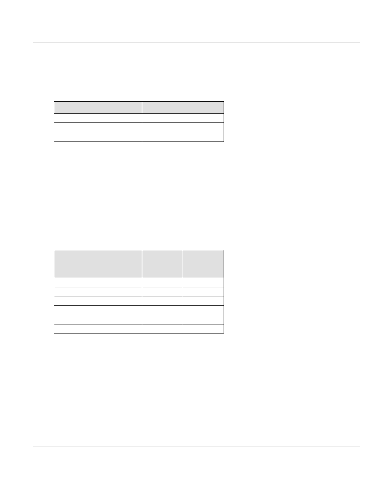
Controller
Firmware
CompactLogix™ 1769-L23
V17.05
CompactLogix™ 1769-L32E
V20.13
CompactLogix™ 1769-L36ERM
V21.11
Processor
I/O (cyclic)
CIP
Messaging
(acyclic)
CompactLogix™ 1769-L23
Yes
Yes
CompactLogix™ 1769-L30
Yes
No
CompactLogix™ 1769-L31
Yes
Yes
CompactLogix™ 1769-L32E
Yes
Yes
CompactLogix™ 1769-L35E
Yes
Yes
CompactLogix™ 1769-L36ERM
Yes
Yes
User Manual PROFIBUS Slave Communication Module
1.3 Reference Systems
The firmware of the ILX69-PBS was developed and tested with the following
CompactLogix™ controller types and firmware revisions.
CompactLogix System
1.4 1769 Programmable Controller Functionality
PROFIBUS DP supports acyclic services through messages. These PROFIBUS DP
services are supported by the Studio 5000 programming tool using CIP messages. Not all of
the 1769 programmable controllers support CIP messaging.
The basic PROFIBUS DP acyclic services Global Control or slave Diagnostics request are
also executable in addition to the CIP method by using the I/O area. The following table
displays the 1769 programmable controllers and the functionalities they support.
CompactLogix System
Yes = Functionality supported
No = Functionality not supported
Page 8 of 102 ProSoft Technology, Inc.
March 20, 2015
Page 9

ILX69-PBS ♦ CompactLogix or MicroLogix Platform Contents
PROFIBUS Slave Communication Module User Manual
1.5 Requirements
1.5.1 Software Requirements
The software requirements for using the ILX69-PBS within a CompactLogix™ system are
listed below. You must have the following software installed on your PC unless otherwise
noted:
CompactLogix System
Studio 5000 programming software, V21.00 or higher
RSLogix™ 5000 programming software, V20.00 or higher
1.5.2 Hardware Requirements
The following minimum hardware is required to use the ILX69-PBS:
Windows PC with SD card slot or SD card reader
Ethernet cable for ILX69-PBS web page connection
CompactLogix System
Personal Computer
1769 – Programmable controller (1769-L23, 1769-L32E and 1769-L36ERM)
1769 – Power supply
1769 – Right or left handed termination end cap
Ethernet cable for interface to the 1769 programmable controller
ProSoft Technology, Inc. Page 9 of 102
March 20, 2015
Page 10

Contents ILX69-PBS ♦ CompactLogix or MicroLogix Platform
User Manual PROFIBUS Slave Communication Module
Page 10 of 102 ProSoft Technology, Inc.
March 20, 2015
Page 11

ILX69-PBS ♦ CompactLogix or MicroLogix Platform Contents
In This Chapter
General Note .........................................................................................11
Personnel Qualification ..........................................................................11
Safety Instructions to Avoid Personal Injury ...........................................11
Safety Instructions to Avoid Property Damage ......................................12
Labeling of Safety Messages .................................................................14
Safety References .................................................................................15
PROFIBUS Slave Communication Module User Manual
2 Safety
2.1 General Note
The documentation in the form of a user manual, an operating instruction manual or other
manual types, as well as the accompanying texts have been created for the use of the
products by educated personnel. When using the products, all Safety Messages, Integrated
Safety Messages, Property Damage Messages and all valid legal regulations must be
obeyed. Technical knowledge is presumed. The user must assure that all legal regulations
are obeyed.
2.2 Personnel Qualification
The ILX69-PBS must only be installed, configured, and removed by qualified personnel.
Job-specific technical skills for people professionally working with electricity must be present
concerning the following topics:
Safety and health at work
Mounting and connecting of electrical equipment
Measurement and analysis of electrical functions and systems
Evaluation of the safety of electrical systems and equipment
Installing and configuring IT systems
2.3 Safety Instructions to Avoid Personal Injury
To ensure your own personal safety and to avoid personal injury, you necessarily must read,
understand and follow the safety instructions and safety messages in this manual before
you install and operate the ILX69-PBS.
ProSoft Technology, Inc. Page 11 of 102
March 20, 2015
Page 12

Contents ILX69-PBS ♦ CompactLogix or MicroLogix Platform
User Manual PROFIBUS Slave Communication Module
2.3.1 Electrical Shock Hazard
The danger of a lethal electrical shock caused by parts with more than 50V may occur if you
power a PLC power supply module when its housing is open.
HAZARDOUS VOLTAGE is present inside of a powered PLC power supply module.
Strictly obey all safety rules provided by the device manufacturer in the documentation.
Disconnect the network power (power plug) from the power supply module before you
disconnect the PLC module from the backplane.
When you disconnect the PLC module from the power supply module, use end cap
terminators and close the power supply module housing.
An electrical shock is the result of a current flowing through the human body. The resulting
effect depends on the intensity and duration of the current and on its path through the body.
Currents in the range of approximately ½ mA can cause effects in persons with good health,
and indirectly cause injuries resulting from startling responses. Higher currents can cause
more direct effects, such as burns, muscle spasms, or ventricular fibrillation.
In dry conditions, permanent voltages up to approximately 42.4 V peak or 60 V are not
considered as dangerous if the contact area is equivalent to the size of a human hand.
More information is located at Safety References (page 15).
2.3.2 Communication Stop During Firmware Update
If you plan a firmware update via the ProSoft web pages, please yield:
During the firmware update procedure, a device reset is performed and stops all module
communication functions with network devices. An unintended plant stop can cause
personal injury.
Initiating a device reset causes a device reboot. A reboot stops all communication
immediately.
Personal injury by consequence of careless use caused plant stop can not be excluded.
All fieldbus devices should be placed in a fail-safe condition under direct supervision
before starting a firmware update.
Before you initiate a reset, make sure your system is in an idle state and operating under
maintenance conditions in order to prevent personal injury.
Stop the PLC program before you start the firmware update.
More firmware update information is located at Firmware Update.
2.4 Safety Instructions to Avoid Property Damage
To avoid system damage and device destruction to the ILX69-PBS, you necessarily must
read, understand and follow the following safety instructions and safety messages in this
manual before you install and operate the ILX69-PBS.
Page 12 of 102 ProSoft Technology, Inc.
March 20, 2015
Page 13
ILX69-PBS ♦ CompactLogix or MicroLogix Platform Contents
Mandatory supply voltage information is located at Power Supply (page 21).
Mandatory signaling voltage information is located at Power Supply (page 21).
PROFIBUS Slave Communication Module User Manual
2.4.1 Device Destruction if ILX69-PBS is Installed to Powered PLC
To avoid device destruction when the ILX69-PBS is powered up:
Strictly obey to all safety rules provided by the PLC device manufacturer documentation.
Shut off the power supply of the PLC, before you install the ILX69-PBS module.
2.4.2 Device Destruction by Exceeding Allowed Supply Voltage
To avoid device destruction due to high supply voltage to the ILX69-PBS, you must observe
the following instructions.
The ILX69-PBS may only be operated with the specified supply voltage. Make sure that
the limits of the allowed range for the supply voltage are not exceeded.
A supply voltage above the upper limit can cause severe damage to the ILX69-PBS.
A supply voltage below the lower limit can cause malfunction in the ILX69-PBS.
The allowed range for the supply voltage is defined by the tolerances specified in this
manual.
2.4.3 Device Destruction by Exceeding Allowed Signaling Voltage
To avoid device destruction due to high signal voltage to the ILX69-PBS, you must observe
the following instructions.
All I/O signal pins at the ILX69-PBS tolerate only the specified signaling voltage.
Operation of the ILX69-PBS with a signaling voltage other than the specified signaling
voltage may lead to severe damage to the module.
2.4.4 Electrostatically sensitive devices
This equipment is sensitive to electrostatic discharge, which can cause internal damage and
affect normal operation. Therefore, adhere to the necessary safety precautions for
components that are vulnerable with electrostatic discharge when handling the ILX69-PBS.
Follow the guidelines listed when you handle this equipment:
Touch a grounded object to discharge potential static.
Wear an approved grounding wrist strap.
Do not touch connectors or pins on the ILX69-PBS.
Do not touch circuit components inside the equipment.
If available, use a static-safe workstation.
When not in use, store the equipment in appropriate static-safe packaging.
More information is located at Safety References (page 15).
ProSoft Technology, Inc. Page 13 of 102
March 20, 2015
Page 14
Contents ILX69-PBS ♦ CompactLogix or MicroLogix Platform
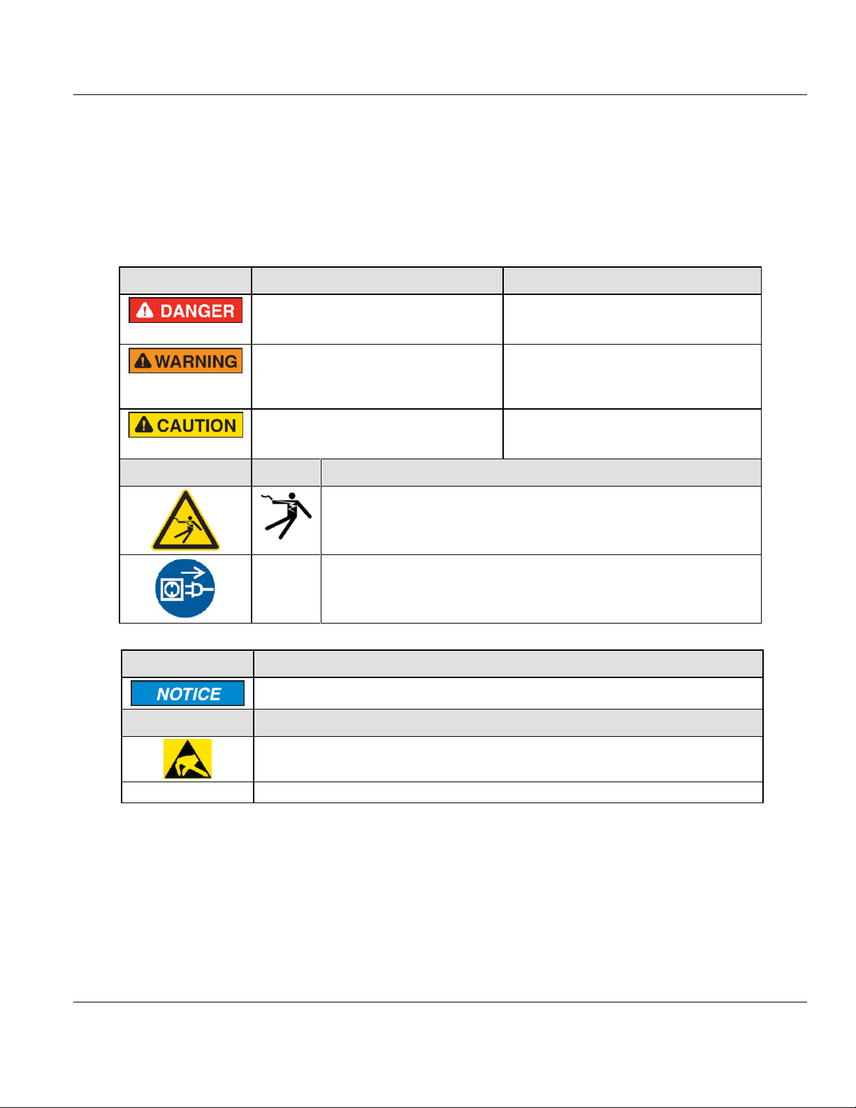
Signal Word
Meaning (International)
Meaning (USA)
Indicates a direct hazard with high risk,
which will have a consequence of death or
grievous bodily harm if it is not avoided.
Indicates a hazardous situation which if not
avoided, will result in death or serious injury.
Indicates a possible hazard with medium
risk, which will have a consequence of
death or (grievous) bodily harm if it is not
avoided.
Indicates a hazardous situation which if not
avoided, could result in death or serious
injury.
Indicates a minor hazard with medium risk,
which could have a consequence of simple
battery if it is not avoided.
Indicates a hazardous situation which if not
avoided, may result in minor or moderate
Injury.
Safety Sign
USA
Warning or Principle
Warning of lethal electrical shock
Principle: Disconnect the power plug
Signal Word
Meaning (International and USA)
Indicates a property damage message.
Safety Sign
Warning or Principle
Warning on damages by electrostatic discharge
-
Example: Warning of device destruction due to exceedingly high supply voltage
User Manual PROFIBUS Slave Communication Module
2.5 Labeling of Safety Messages
The Safety Messages at the beginning of a chapter are pinpointed particularly and
highlighted by a signal word according to the degree of endangerment. The type of
danger is specified by the safety message text and optionally by a specific safety sign.
The Integrated Safety Messages within an instruction description are highlighted with a
signal word according to the degree of endangerment. The type of danger is specified by
the safety message text.
In this document, all Safety Instructions and Safety Messages are designed according both
to the international used safety conventions as well as to the ANSI Z535.6 standard, refer to
Safety References (page 15).
In this document, the signal words ‘WARNING’, ‘CAUTION’ and ‘NOTICE’ are used
according to ANSI Z535.6 standard. The meaning given in ISO/IEC 26514 [4] section ‘11.11
Contents of warnings and cautions is not relevant in this manual.
Page 14 of 102 ProSoft Technology, Inc.
March 20, 2015
Page 15

ILX69-PBS ♦ CompactLogix or MicroLogix Platform Contents
[S1]
ANSI Z535.6-2006 American National Standard for Product Safety Information in Product
Manuals, Instructions, and Other Collateral Materials
[S2]
IEC 60950-1, Information technology equipment - Safety - Part 1: General requirements, (IEC
60950-1:2005, modified); German Edition EN 60950-1:2006
[S3]
EN 61340-5-1 and EN 61340-5-2 as well as IEC 61340-5-1 and IEC 61340-5-2
[S4]
26514-2010 - IEEE Standard for Adoption of ISO/IEC 26514:2008 Systems and Software
Engineering--Requirements for Designers and Developers of User Documentation
PROFIBUS Slave Communication Module User Manual
2.6 Safety References
ProSoft Technology, Inc. Page 15 of 102
March 20, 2015
Page 16

Contents ILX69-PBS ♦ CompactLogix or MicroLogix Platform
User Manual PROFIBUS Slave Communication Module
Page 16 of 102 ProSoft Technology, Inc.
March 20, 2015
Page 17

ILX69-PBS ♦ CompactLogix or MicroLogix Platform Contents
In This Chapter
Device Drawing ILX69-PBS ...................................................................17
PROFIBUS Interface..............................................................................18
Ethernet Interface ..................................................................................20
Removable Memory Card ......................................................................21
Power Supply .........................................................................................21
PROFIBUS Slave Communication Module User Manual
3 About the ILX69-PBS
3.1 Device Drawing ILX69-PBS
ProSoft Technology, Inc. Page 17 of 102
March 20, 2015
Page 18
Contents ILX69-PBS ♦ CompactLogix or MicroLogix Platform
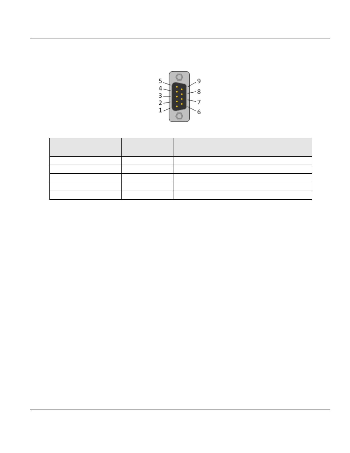
Connection with DSub female connector
Signal
Description
3
RxD / TxD-P
Receive/Send Data-P, respectively connection B plug
4
CNTR-P
Repeater-Control
5
DGND
Data Ground
6
VP
Positive supply voltage
8
RxD / TxD-N
Receive/Send Data-N, respectively connection A plug
User Manual PROFIBUS Slave Communication Module
3.2 PROFIBUS Interface
PROFIBUS Interface (D-Sub female connector, 9 pin):
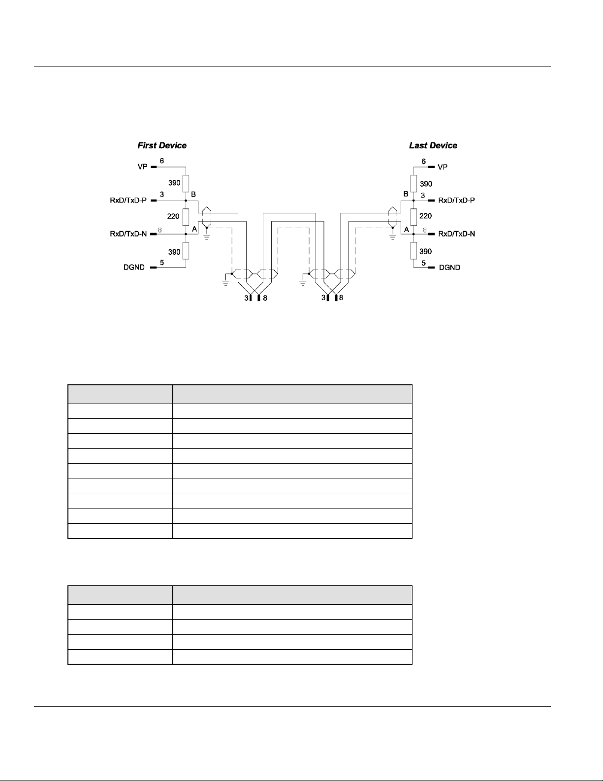
3.2.1 Wiring Instructions
Please ensure that termination resistors are available at both ends of the PROFIBUS
network cable. If special PROFIBUS connectors are being used, these resistors are often
found inside the connector and must be switched on at each end of the PROFIBUS network
cable.
For baud rates above 1.5 MBaud, use only special connectors for higher baud rates. These
include additional inductance.
It is not permitted to have T-stubs on PROFIBUS high baud rates. Use only a special cable
which is approved for PROFIBUS DP. Make a solid connection from the cable shield to
ground at every device and make sure that there is no potential difference between the
grounds at the devices.
Page 18 of 102 ProSoft Technology, Inc.
March 20, 2015
Page 19
ILX69-PBS ♦ CompactLogix or MicroLogix Platform Contents
Baud rate in kBit/s
Maximum distance
9.6 1,200 meters
3,940 feet
19.2
1,200 m
3,940 ft
93.75
1,200 m
3,940 ft
187.5
1,000 m
3,280 ft
500 400 m
1,310 ft
1,500
200 m
656 ft
3,000
100 m
328 ft
6,000
100 m
328 ft
12,000
100 m
328 ft
Parameter
Value
Impedance
35 to 165 Ohm at frequencies from 3 to 20 Mhz
Capacity per units length
< 30 pF/m
Loop resistance
110 Ohm/km
Wire gauge
0.64 mm
PROFIBUS Slave Communication Module User Manual
If the ILX69-PBS is linked with only one other device on the bus, both devices must be
connected to the ends of the bus line. These devices must deliver the supply voltage for the
termination resistors. If three or more devices are connected to the bus, the ILX69-PBS can
be connected at any desired position.
Up to 32 PROFIBUS devices can be connected to one bus segment, without repeaters. If
several bus segments are linked to each other with repeaters, there can be up to 127
devices on the network.
The maximum permissible cable length of a PROFIBUS segment depends on the baud rate
used, see the following table.
Only PROFIBUS certified cables, preferably the cable type A, should be used. The following
table contains important electrical data concerning PROFIBUS certified cable:
ProSoft Technology, Inc. Page 19 of 102
March 20, 2015
Page 20
Contents ILX69-PBS ♦ CompactLogix or MicroLogix Platform
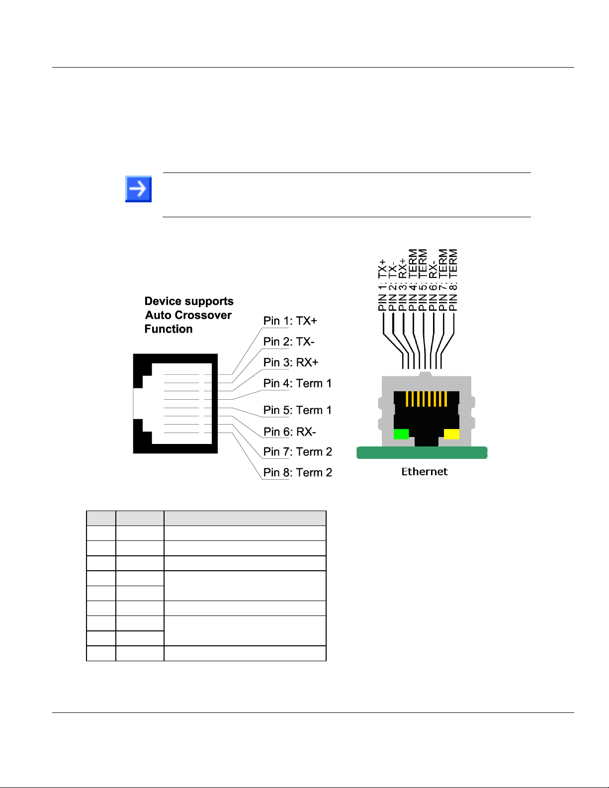
Note: The device supports the Auto Crossover function. The RX and TX
can be switched. The following figure shows the RJ45 standard pin
assignment.
Pin
Signal
Description
1
TX+
Transmit Data +
2
TX–
Transmit Data –
3
RX+
Receive Data +
4
Term 1
Connected to each other and
terminated to PE through RC circuit*
5
Term 1
6
RX–
Receive Data –
7
Term 2
Connected to each other and
terminated to PE through RC circuit*
8
Term 2
*Bob Smith Termination
User Manual PROFIBUS Slave Communication Module
3.3 Ethernet Interface
The Ethernet cable should contain an RJ45 connector. It should have a twisted pair cable of
category 5 (CAT5) or higher, which consists of 4 twisted cores and has a maximum
transmission rate of 100 MBit/s (CAT5).
3.3.1 Ethernet Pin Assignment at the RJ45 Socket
Page 20 of 102 ProSoft Technology, Inc.
March 20, 2015
Page 21
ILX69-PBS ♦ CompactLogix or MicroLogix Platform Contents
Medium
2 x 2 Twisted-pair copper cable, CAT5 (100 MBit/s) or better
Length of cable
Maximum 100 m
Transmission rate
10 MBit/s / 100 MBit/s
Type
SD card (HDSC format is not supported)
Maximum storage capacity
4 GByte
Required formatting
FAT16 format (no FAT32)
Power supply
5V from backplane
Current Load
CompactLogix
570 mA Max. @ 5 VDC
Power rating of 2
Backplane power
5 VDC: Min: 4.75 V at Module; Max: 5.40 V at Module
24 VDC: Min: 19.9 V at Module; Max: 26.4 V at Module
PROFIBUS Slave Communication Module User Manual
3.3.2 Ethernet Connection Data
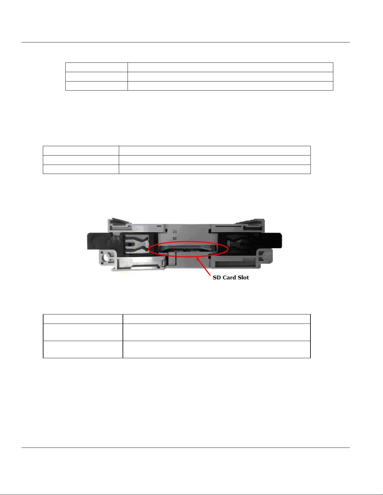
3.4 Removable Memory Card
Memory Card
SD Card Connector
SD Card Connector, e.g. FPS009-2405-0 push/push
3.5 Power Supply
ProSoft Technology, Inc. Page 21 of 102
March 20, 2015
Page 22

Contents ILX69-PBS ♦ CompactLogix or MicroLogix Platform
User Manual PROFIBUS Slave Communication Module
Page 22 of 102 ProSoft Technology, Inc.
March 20, 2015
Page 23

ILX69-PBS ♦ CompactLogix or MicroLogix Platform Contents
In This Chapter
Consideration when planning the system ..............................................23
ILX69-PBS Hardware Installation ..........................................................23
Uninstalling ILX69-PBS Hardware .........................................................25
PROFIBUS Slave Communication Module User Manual
4 Installation
4.1 Consideration when planning the system
Issues for the Network Conception
The ILX69-PBS has address rotary switches to set an station address from 0 to 99. If set
to 0, address will be taken from the configuration assembly. Using the PLCs
configuration data, an address range from 0 to 125 is adjustable.
The ILX69-PBS is capable of automatic baud rate detection.
A 1769-ECR (right end cap) or 1769-ECL (left end cap) is required to terminate the end
of the Compact I/O bus.
Each bank of Compact I/O must have its own power supply.
A Compact I/O power supply has limits on the amount of +5 VDC and +24 VDC current it
can supply to modules in its I/O bank. These limits depend on the catalog number (e.g.
1769-PA2) of the supply. A bank of modules must not exceed the current limits of the I/O
bank power supply. Refer to the Compact 1769 Expansion I/O Power Supplies
Installation Instructions.
The ILX69-PBS has a distance rating of 2. Therefore, the module must be within 2 slots
of the I/O bank’s power supply.
Configuration and Network Communication
Determine the PROFIBUS baud rate based on standard PROFIBUS system
considerations.
Identify the number of words of I/O data each slave supports.
ProSoft Technology, Inc. Page 23 of 102
March 20, 2015
Page 24
Contents ILX69-PBS ♦ CompactLogix or MicroLogix Platform
Electrostatically sensitive devices
To prevent damage to the PLC and the ILX69-PBS, make sure that the ILX69-PBS is
grounded via the backplane of the PLC. Also make sure that you are discharged when
you install/uninstall the ILX69-PBS.
Device Destruction
Shut off the power supply of the PLC before you install the ILX69-PBS. Then install or
remove the ILX69-PBS to/from the PLC..
Use only the permissible supply voltage to operate the ILX69-PBS.
All I/O signal pins at the ILX69-PBS tolerate only the specified signaling voltage.
A detailed description the installation of communication modules in
CompactLogix™ systems can be found in the installation manual for the
1769 CompactLogix™ controller from Rockwell Automation.
User Manual PROFIBUS Slave Communication Module
4.2 ILX69-PBS Hardware Installation
This section describes how to install/uninstall the ILX69-PBS into a CompactLogix™ system.
4.2.1 Safety Precautions
Obey the following property damage messages when installing, uninstalling or replacing the
ILX69-PBS.
4.2.2 Installing the ILX69-PBS Module
1 Install the ILX69-PBS into a free slot in the CompactLogix™ controller. Make sure it is
within 2 slots of a power supply.
2 Check that the bus lever of the ILX69-PBS is in the unlocked (fully right) position.
3 Assemble the ILX69-PBS and the CompactLogix™ module together by using the upper
and lower tongue-and-groove slots.
4 Move the ILX69-PBS back along the tongue-and-groove slots until the bus connectors
line up with each other.
5 Move the ILX69-PBS bus lever fully to the left until it clicks. Ensure it is locked firmly in
place.
6 Attach and lock an end cap terminator to the ILX69-PBS by using the tongue-and-groove
slots as before.
7 Apply power to the Rockwell CompactLogix™ controller.
Page 24 of 102 ProSoft Technology, Inc.
March 20, 2015
Page 25

ILX69-PBS ♦ CompactLogix or MicroLogix Platform Contents
PROFIBUS Slave Communication Module User Manual
4.3 Uninstalling ILX69-PBS Hardware
1 Adhere to the safety precautions.
2 Shut off the power of the Rockwell CompactLogix™ controller.
3 Discharge yourself.
4 Unlock the end cap bus terminator.
5 Remove the end cap terminator from the ILX69-PBS by using the tongue-and-groove
slots.
6 Move the ILX69-PBS bus lever in the unlocked (fully right) position.
7 Remove the ILX69-PBS along the tongue-and-groove slots.
8 Reassemble the end cap terminator and the CompactLogix™ system together by using
the upper and lower tongue-and-groove slots.
ProSoft Technology, Inc. Page 25 of 102
March 20, 2015
Page 26

Contents ILX69-PBS ♦ CompactLogix or MicroLogix Platform
User Manual PROFIBUS Slave Communication Module
Page 26 of 102 ProSoft Technology, Inc.
March 20, 2015
Page 27

ILX69-PBS ♦ CompactLogix or MicroLogix Platform Contents
In This Chapter
Creating the Module in an RSLogix 5000 Project ..................................27
Slave Configuration ...............................................................................45
SD Card ................................ ................................................................ .49
PROFIBUS Slave Communication Module User Manual
5 Configuration and Start-Up
This chapter provides descriptions about the configuration and start-up of the ILX69-PBS.
ILX69-PBS Configuration and Parameterization Steps:
The configuration and parameterization of the ILX69-PBS is carried out in three steps:
1 Configuration of the module in a CompactLogix™ project of the Studio 5000 or RSLogix
5000 programming tool.
2 Parameterization and configuration of the ILX69-PBS using the master configuration
software. The slave module can use this configuration during startup.
3 Creating the data objects and the ladder diagram in Studio 5000/RSLogix 5000.
5.1 Creating the Module in an RSLogix 5000 Project
In an RSLogix 5000 project, there are two ways you can add the ILX69-PBS module to the
project.
You can use an Add-On Profile (AOP) from ProSoft Technology. The AOP contains all
the configuration information needed to add the module to the project. This is the
preferred way, but requires RSLogix version 15 or later.
You can manually create the module using a generic 1769 profile, and then manually
configure the module parameters. Use this method if you have RSLogix version 14 or
earlier.
ProSoft Technology, Inc. Page 27 of 102
March 20, 2015
Page 28

Contents ILX69-PBS ♦ CompactLogix or MicroLogix Platform
User Manual PROFIBUS Slave Communication Module
5.1.1 Creating a Module in the Project Using an Add-On Profile
Installing an Add-On Profile
Download the MPSetup.exe file from the product web page (found at
http://www.prosoft-technology.com) or from the ProSoft Solutions DVD onto the local hard
drive. Make sure RSLogix 5000 and RSLinx have been shut down before installing the AddOn Profile (AOP).
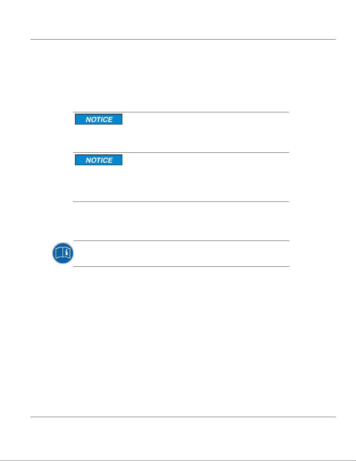
1 Run the MPSetup.exe file to start the Setup Wizard. Follow the Setup Wizard to install
the AOP. (The version may be different than shown below).
Page 28 of 102 ProSoft Technology, Inc.
March 20, 2015
Page 29
ILX69-PBS ♦ CompactLogix or MicroLogix Platform Contents
PROFIBUS Slave Communication Module User Manual
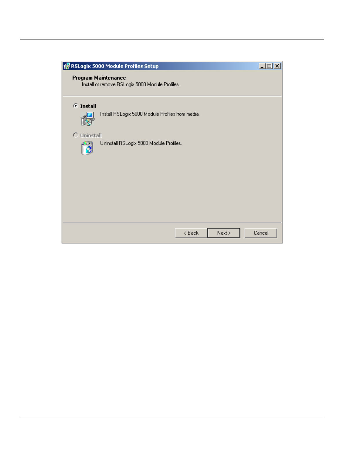
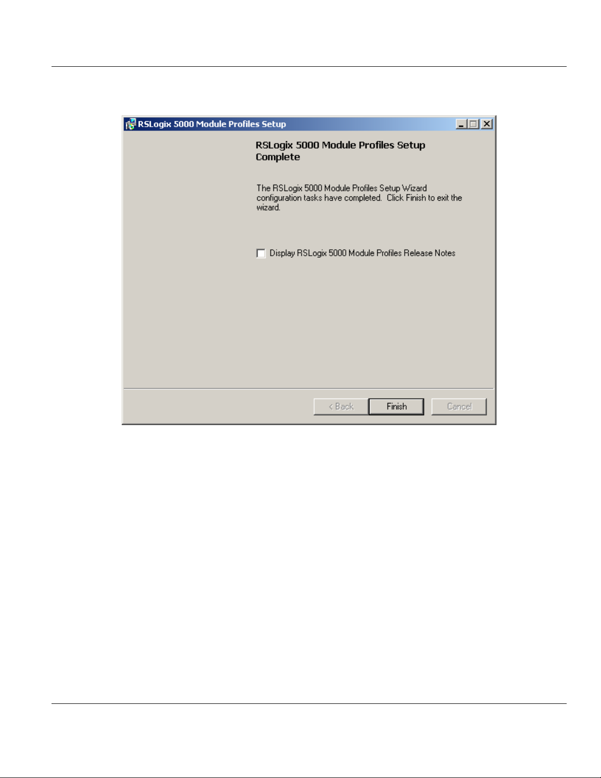
2 Continue to follow the steps in the wizard to complete the installation.
ProSoft Technology, Inc. Page 29 of 102
March 20, 2015
Page 30
Contents ILX69-PBS ♦ CompactLogix or MicroLogix Platform
User Manual PROFIBUS Slave Communication Module
3 Click FINISH when complete. The AOP is now installed in RSLogix 5000. You do not
need to reboot the PC.
Page 30 of 102 ProSoft Technology, Inc.
March 20, 2015
Page 31

ILX69-PBS ♦ CompactLogix or MicroLogix Platform Contents
PROFIBUS Slave Communication Module User Manual
Using an Add-On Profile
1 In RSLogix 5000, expand the I/O CONFIGURATION folder in the Project tree. Right-click
the appropriate communications bus and choose NEW MODULE.
This opens the Select Module Type dialog box. In the Module Type Vendor Filters area,
uncheck all boxes except the PROSOFT TECHNOLOGY box. A list of ProSoft Technology
modules appears in the dialog box.
ProSoft Technology, Inc. Page 31 of 102
March 20, 2015
Page 32

Contents ILX69-PBS ♦ CompactLogix or MicroLogix Platform
User Manual PROFIBUS Slave Communication Module
2 Select the ILX69-PBS module in the list and click CREATE:
Page 32 of 102 ProSoft Technology, Inc.
March 20, 2015
Page 33

ILX69-PBS ♦ CompactLogix or MicroLogix Platform Contents
PROFIBUS Slave Communication Module User Manual
3 A New Module dialog box opens. In the GENERAL tab, enter "ILX69PBS" in the NAME
field and the appropriate SLOT for the module.
4 Click on the CONFIGURATION tab (Offline). This option assigns the IP Address, Subnet
Mask, and Gateway Address of the module. If applicable, select MANUALLY CONFIGURE
IP SETTINGS from the IP Settings field to manually enter your values.
ProSoft Technology, Inc. Page 33 of 102
March 20, 2015
Page 34

Contents ILX69-PBS ♦ CompactLogix or MicroLogix Platform
User Manual PROFIBUS Slave Communication Module
5 Click on the ADVANCED tab (Offline). This option assigns the STATION ADDRESS
(PROFIBUS Slave ID) of the ILX69-PBS.
It also determines how the ILX69-PBS obtains its configuration by CONFIGURATION TYPE.
In most applications, OBTAIN FROM MASTER is sufficient. With this option, the
configuration is done within the PROFIBUS master software and sent to the ILX69-PBS.
The OBTAIN FROM LADDER option is a unique option that allows the CompactLogix
controller to "lock" the ILX69-PBS PROFIBUS configuration. Once this option is
selected, you will manually configure the PROFIBUS I/O data in the Module
Configuration section of the tab. The PROFIBUS Master’s configuration for this slave
must match 100%, or communications will fail.
6 Click OK.
7 The ILX69-PBS module is now visible in the I/O Configuration tree.
Page 34 of 102 ProSoft Technology, Inc.
March 20, 2015
Page 35

ILX69-PBS ♦ CompactLogix or MicroLogix Platform Contents
PROFIBUS Slave Communication Module User Manual
5.1.2 Manually Creating a Module in the Project
This section covers the manual configuration of the ILX69-PBS in a CompactLogix™
system. When complete, please see Configuration by Controller Application 46 for modulespecific configuration parameters.
Creating a New Project
1 Open the FILE menu, and select NEW.
2 Select your controller TYPE and REVISION 16 or newer.
3 Click OK.
4 Right click on the I/O configuration > CompactBus Local of the controller project.
ProSoft Technology, Inc. Page 35 of 102
March 20, 2015
Page 36

Contents ILX69-PBS ♦ CompactLogix or MicroLogix Platform
User Manual PROFIBUS Slave Communication Module
5 Select New Module from the context menu as shown below.
The following dialog box appears.
6 Select "1769-MODULE Generic 1769 module" and click OK. The Module Properties
dialog will open.
Page 36 of 102 ProSoft Technology, Inc.
March 20, 2015
Page 37

ILX69-PBS ♦ CompactLogix or MicroLogix Platform Contents
PROFIBUS Slave Communication Module User Manual
Module Properties 1
1 The communications parameters for the module should be set as shown in the dialog
below.
2 Enter PBS as the NAME and enter a short description for the module.
3 Select the Slot number in which the module is installed in the CompactLogix system. It
must be within 2 slots of a power supply.
4 Select Data - INT as the Comm_Format.
5 Set the Connection Parameters as they are shown in the dialog above.
6 Select Next >> or OK for the next configuration dialog.
ProSoft Technology, Inc. Page 37 of 102
March 20, 2015
Page 38

Contents ILX69-PBS ♦ CompactLogix or MicroLogix Platform
User Manual PROFIBUS Slave Communication Module
Module Properties 2
The Requested Packet Interval RPI is shown in the following dialog. Within this time interval,
the I/O data between module and controller are exchanged.
1 Edit the REQUESTED PACKET INTERVAL (RPI) value, if needed.
2 Click Finish>>
3 Save the project.
Page 38 of 102 ProSoft Technology, Inc.
March 20, 2015
Page 39

ILX69-PBS ♦ CompactLogix or MicroLogix Platform Contents
PROFIBUS Slave Communication Module User Manual
5.1.3 Importing the Ladder Rung
1 In the Controller Organization window, expand the TASKS folder and subfolder until you
reach the MAINPROGRAM folder.
2 In the MAINPROGRAM folder, double-click to open the MAINROUTINE ladder.
3 Select an empty rung in the new routine, and then click the right mouse button to open a
shortcut menu. On the shortcut menu, choose IMPORT RUNGS.
4 Navigate to the location on your PC where the .L5X Add-On Instruction (for example, My
Documents or Desktop) is saved. Select IMPORT...
ProSoft Technology, Inc. Page 39 of 102
March 20, 2015
Page 40

Contents ILX69-PBS ♦ CompactLogix or MicroLogix Platform
User Manual PROFIBUS Slave Communication Module
This action opens the Import Configuration dialog box, showing the controller tags that
will be created.
5 Verify that the slot number is correct for the module in the Local:x tags. This must match
the physical slot number location of the ILX69-PBS in the CompactLogix™ bus.
Page 40 of 102 ProSoft Technology, Inc.
March 20, 2015
Page 41

ILX69-PBS ♦ CompactLogix or MicroLogix Platform Contents
PROFIBUS Slave Communication Module User Manual
6 Click OK to confirm the import.
When the import is completed, the new Add-On Instruction rung will appear in the
ladder.
The procedure has also imported new user-defined data types, controller tags and the
Add-On instruction for your project.
7 Save the project.
ProSoft Technology, Inc. Page 41 of 102
March 20, 2015
Page 42

Contents ILX69-PBS ♦ CompactLogix or MicroLogix Platform
User Manual PROFIBUS Slave Communication Module
Read Request
When the AOI is imported into the project, the ILX69-PBS MSG tags reference slot 1 in its
path configuration. If the ILX69-PBS is not located in slot 1, you will need to edit the MSG
instruction Communication Path to the proper slot number.
1 Locate the MSG instructions within the ILX69-PBS AOI rung.
2 To edit a MSG instruction, click on the "..." box to open the Message Configuration
window.
Page 42 of 102 ProSoft Technology, Inc.
March 20, 2015
Page 43

ILX69-PBS ♦ CompactLogix or MicroLogix Platform Contents
PROFIBUS Slave Communication Module User Manual
3 Select the COMMUNICATION tab at the top of the window. Click BROWSE... to open the
Message Path Browser window.
4 In the Message Path Browser window, select the slot location of the ILX69-PBS. The
Path field updates when the module is selected. Click OK.
ProSoft Technology, Inc. Page 43 of 102
March 20, 2015
Page 44

Contents ILX69-PBS ♦ CompactLogix or MicroLogix Platform
User Manual PROFIBUS Slave Communication Module
5 Back In the Message Configuration window, the Path field shows the ILX69-PBS
properly in place. Click APPLY, then click OK.
6 Repeat these steps for each MSG instruction in the ILX69-PBS AOI.
7 Save the project. It is ready to be downloaded to the CompactLogix™ controller.
Page 44 of 102 ProSoft Technology, Inc.
March 20, 2015
Page 45

ILX69-PBS ♦ CompactLogix or MicroLogix Platform Contents
Note: The PROFIBUS DP master can send a new configuration to the slave at
any time. This can cause inconsistency if the new configuration does not match
to the controller application. A safer method can be done by "Configuration by
Controller Application" located in the next section. With this method, the slave
module does not start any communication as long as the slave configuration
and the master configuration do not match to each other.
PROFIBUS Slave Communication Module User Manual
5.2 Slave Configuration
The following section details the basics the ILX69-PBS configuration.
There are two ways to configure the ILX69-PBS:
Configuration by Master
With the PROFIBUS master and ILX69-PBS connected on the network, the slave
configuration is sent from the master to the ILX69-PBS during PROFIBUS network startup.
Configuration by Controller Application
The slave configuration can be loaded via configuration parameters from the
CompactLogix™ PLC program to the ILX69-PBS.
5.2.1 GSD File
A GSD (Generic Station Description) file is an electronic datasheet used for a particular
PROFIBUS slave device. The ILX69-PBS GSD file contains the information that is specific
to the ILX69-PBS.
The ILX69-PBS GSD file is named "PSFT0EE1.GSD". It is located on the ProSoft Solutions
DVD. You must provide this file to the PROFIBUS master configuration software. Refer to
the master's documentation of how to import GSD files.
5.2.2 Configuration by Master
Configuration by Master is the easiest way to configure the slave. The ILX69-PBS sample
ladder and AOI contains the use of this method. This example is described in section Studio
5000 Example Program.
During the network startup phase, the PROFIBUS master sends the expected slave
configuration over the network to compare it with the real configuration of the slaves
connected to the bus. The ILX69-PBS automatically takes over the configuration which is
sent by the master during its comparison of the configuration. This method is activated by
default, since the parameter "Force User Config" in the configuration area is set to 0. The
only setting required by the user is setting the Address rotary switches on the front of the
ILX69-PBS.
ProSoft Technology, Inc. Page 45 of 102
March 20, 2015
Page 46

Contents ILX69-PBS ♦ CompactLogix or MicroLogix Platform
Word
Offset
Configuration
word
Data
type
Low/High
Byte
Description
Valid values
0
Local:1:C.Data[0]
INT
LOW Byte
Reconfiguration Event 0
Reserved, set to 0
HIGH Byte
Reconfiguration Event 1
1
Local:1:C.Data[1]
INT
LOW Byte
Reconfiguration Event 2
Reserved, set to 0
HIGH Byte
Reconfiguration Event 3
2
Local:1:C.Data[2]
INT
LOW Byte
Bus Address
0 to 125
0 = ForceMasterConfig
1 = ForceUserConfig
HIGH Byte
Force User Configuration
3
Local:1:C.Data[3]
INT Reserved
4
Local:1:C.Data[4]
INT Watchdog Time
0 to FFFFh
5
Local:1:C.Data[5]
INT Number of valid config bytes
(starting with Local:1:C.Data[8])
2 to 48
6
Local:1:C.Data[6]
INT Reserved
7 Local:1:C.Data[7]
INT Reserved
8
Local:1:C.Data[8]
INT
LOW Byte
Module 1 Type
HIGH Byte
Module 1 Length
9
Local:1:C.Data[9]
INT
LOW Byte
Module 2 Type
HIGH Byte
Module 2 Length
...
...
...
...
31
Local:1:C.Data[31]
INT
LOW Byte
Module 24 Type
HIGH Byte
Module 24 Length
32
Local:1:C.Data[32]
BOOL
-
IP Config flags 1, Static or
Dynamic
0 or 1
33
Local:1:C.Data[33]
BOOL
-
IP Config flags 2, Static or
Dynamic
0 or 1
34
Local:1:C.Data[34]
INT - IP Configuration
0 = BOOTP
1 = DHCP
2 = FIXED IP
35
Local:1:C.Data[35]
SINT
LOW Byte
IP Address
00.00.00.00 through
FF.FF.FF.FF
…
…
HIGH Byte
User Manual PROFIBUS Slave Communication Module
5.2.3 Configuration by Controller Application
The second option to configure the ILX69-PBS is through the controller application. If you’re
unable to install the AOP due to company policy or other reasons, you will need to manually
configure the module through the controller application.
The "Force User Config" parameter in this array must be set to 1. With this method, the
ILX69-PBS will not start any network communication unless the master and ILX69-PBS
configuration match. The following table outlines the mapping of the configuration data
image.
Page 46 of 102 ProSoft Technology, Inc.
March 20, 2015
Page 47

ILX69-PBS ♦ CompactLogix or MicroLogix Platform Contents
Word
Offset
Configuration
word
Data
type
Low/High
Byte
Description
Valid values
37
Local:1:C.Data[37]
SINT
LOW Byte
Net Mask
00.00.00.00 through
FF.FF.FF.FF
…
…
HIGH Byte
39
Local:1:C.Data[39]
SINT
LOW Byte
Gateway Address
00.00.00.00 through
FF.FF.FF.FF
…
…
HIGH Byte
41
Local:1:C.Data[41]
- - Reserved
Set to 0
Address
Switches
Configuration
Address Parameter
Active
Bus Address
Description
1 to 99
N/A
1 to 99
Address switches are valid
0
0 to 125
0 to 125
Configuration parameter is valid
0
> 125
N/A
Invalid (will cause an initialization error)
PROFIBUS Slave Communication Module User Manual
5.2.4 Configuration Parameters
Bus Address
The ILX69-PBS has two rotating address switches to set the network address from 0 to 99.
If you need to assign the ILX69-PBS to an address above 99, set both address switches to
0. The module will take the address parameter from the configuration data array.
Force User Configuration
If this value is set to 1, the ILX69-PBS will not start network communication until the master
and slave configurations match.
If this value is set to 0, the slave accepts the configuration sent from the master.
ProSoft Technology, Inc. Page 47 of 102
March 20, 2015
Page 48

Contents ILX69-PBS ♦ CompactLogix or MicroLogix Platform
Parameter
Data Type
Valid values
Description
Module Type
SINT
0 = IN Byte
1 = IN Word
2 = OUT Byte
3 = OUT Word
4 = IN Byte con
5 = IN Word con
6 = OUT Byte con
7 = OUT Word con
8 = Blank space
Input Byte without consistence
Input Word without consistence
Output Byte without consistence
Output Word without consistence
Input Byte with consistence
Input Word with consistence
Output Byte with consistence
Output Word with consistence
Blank space
Module Length
SINT
0
1
2
3
4
5
6
7
8
9
1 Byte/Word
2 Byte/Word
3 Byte/Word
4 Byte/Word
8 Byte/Word
12 Byte/Word
16 Byte/Word
20 Byte/Word
32 Byte/Word
64 Byte/Word
User Manual PROFIBUS Slave Communication Module
Watchdog Timeout
The ILX69-PBS supervises its I/O exchange with the controller within a specific time frame.
If the controller does not update the output data within this time, the slave stops the cyclic
data exchange with the master and goes into a safe state.
If the ‘ForceUserConfiguration’ parameter is set to 0, the ILX69-PBS automatically
calculates a timeout value by the RPI (Requested Packet Intervall). The calculated
watchdog calculates to 2x the RPI (+/- 5ms). The smallest watchdog value is 15 ms. The
module rounds the watchdog value to multiples of 5 ms.
WATCHDOG_TIME (ms) = MAX ( 2 x RPI)
If the "ForceUserConfiguration" parameter is set to 1, the ILX69-PBS will take the watchdog
value from the configuration array. Make sure the watchdog value is not smaller than the
RPI. The ILX69-PBS rounds the watchdog to multiples of 5ms.
Number of Valid Configuration Bytes
This parameter holds the number of valid configuration bytes that define PROFIBUS
Input/Output modules.
Module Type / Module Length
The ILX69-PBS offers a flexible, modular composition of its I/O data. Parts of the input and
output image can be viewed as single modules. The master can put the different modules
from the ILX69-PBS to different locations in its I/O area. The individually configured modules
are mapped linearly in the I/O area of the ILX69-PBS. It is possible to configure up to 24 I/O
modules. A module is defined by a Module Type and its Module Length:
Page 48 of 102 ProSoft Technology, Inc.
March 20, 2015
Page 49

ILX69-PBS ♦ CompactLogix or MicroLogix Platform Contents
Note: Please notice the definition of Input/Output modules and do not
confuse them with the input and output area of the ILX69-PBS in the
controller memory map.
Inputs and Outputs modules are always defined from viewpoint of the
PROFIBUS master. If you configure an Output module, you will see this in
the input area of the ILX69-PBS, because the input area of the controller
memory map is the output area from point of view of a PROFIBUS master.
The same applies to an Input module. If you define an Input module, it is
mapped in the output area of the controller memory map, because the
output area of the ILX69-PBS is the input area from viewpoint of a
PROFIBUS master.
PROFIBUS Slave Communication Module User Manual
The sample ladder and AOI can also be used as an example for a module configuration by
the controller application. You only have to set the "ForceUserConfiguration" parameter from
0 to 1 in the configuration array. Section Studio 5000 Example Program explains the predefined configuration parameter of the sample ladder/AOI.
5.3 SD Card
5.3.1 Start-up Behavior with or without SD Card
The start-up behavior of the ILX69-PBS depends on whether an SD memory card is inserted
in the module or not.
Start-up without Memory Card
On power-up, the ILX69-PBS and the firmware are started and the configuration data is
loaded from the CompactLogix processor using the Local:x:C.Data array into the ILX69-PBS
internal flash memory. Depending on the amount of stored configuration data, this can last
for approximately 4 seconds.
Start-up with Memory Card
The ILX69-PBS supports firmware upgrade utilizing an optional SD card. Contact ProSoft
technical support to obtain this firmware image. Firmware can also be loaded via the ILX69PBS webpage. Configuration of the module is always obtained from the Local:x:C.Data
array from the CompactLogix processor.
On power-up, the firmware data are restored from the SD memory card flash image into the
ProSoft Technology, Inc. Page 49 of 102
March 20, 2015
ILX69-PBS internal flash memory only when the ILX69-PBS is not connected over the
backplane to a CompactLogix processor. The following is the power-up sequence:
Page 50

Contents ILX69-PBS ♦ CompactLogix or MicroLogix Platform
Note: The STARTUPINI file is automatically created if ‘Store’ and
are used. The user does not need to create this file.
User Manual PROFIBUS Slave Communication Module
After return of power, the SYS LED indicates a fast blinking in green for approximately
10 seconds. During this time the SD memory card can be removed from the module to
prevent the data transfer.
o After 10 seconds, the following files are transferred from the SD memory card into
the non-volatile flash memory of the ILX69-PBS:
• Firmware *.nxf
• Web pages
This operation takes (typically) up to 30 seconds. During this operation the SYS LED
is static yellow.
When complete, the new firmware starts automatically and the ILX69-PBS boots with the
new configuration. The COM LED illuminates or blinks as described in section
Communication Status. Connection over the backplane to the CompactLogix processor
can then be restored.
5.3.2 STARTUP.INI File
The STARTUP.INI file contains the following:
1 [Global]
2 Notify=10
3 Restore=always
4 RestorePoint=SDMMC:/backup
Notify=10: The value for ‘Notify’ is ‘10’. It takes 10 seconds to copy the files from the SD
memory card to the internal flash of the ILX69-PBS.
Restore=always: The second stage bootloader copies the files in any case.
RestorePoint=SDMMC:/backup: All data stored under the backup folder is copied to the
SD memory card.
5.3.3 Reset Device to Factory Settings with Memory Card
Using a memory card that has the basic firmware stored on it, the ILX69-PBS can be
restored back to factory settings.
1 Copy the STARTUP.INI file and the backup directory (including all subdirectories) from
the ProSoft Solutions DVD into the root directory of an empty memory card.
2 Prepare the memory card and reset the module to the factory settings as described in
section Steps for Project File Backup and SD Card Handling.
Page 50 of 102 ProSoft Technology, Inc.
March 20, 2015
Page 51

ILX69-PBS ♦ CompactLogix or MicroLogix Platform Contents
In This Chapter
Studio 5000 PROFIBUS Data Values ....................................................51
I/O Communication and Memory Map ...................................................52
Acyclic Messaging .................................................................................60
PROFIBUS Slave Communication Module User Manual
6 Communication
6.1 Studio 5000 PROFIBUS Data Values
The ILX69-PBS PROFIBUS network data values (input and output) are located in the
Controller Tags of Studio 5000.
6.1.1 PROFIBUS Network Output Data
The PROFIBUS network data received from the PROFIBUS master (output data) is stored in
the ILX69PBS.DATA.INPUT array.
ProSoft Technology, Inc. Page 51 of 102
March 20, 2015
Page 52

Contents ILX69-PBS ♦ CompactLogix or MicroLogix Platform
Offset
Register Type
Name
0
Device Status Register
Status Bits
1
Reserved
Reserved
2
Reserved
Reserved
3
Reserved
Reserved
4
Firmware Revision
Minor Version
5
Firmware Revision
Major Version
6 to 7
Reserved
Reserved
8 to 9
Slave Status Information
ExtStaSelect
10 to 11
Slave Status Information
ExtStaLen
12 to 13
Slave Status Information
Baudrate
14
Slave Status Information
Busaddress
15
Slave Status Information
UserFlags
16 to 17
Slave Status Information
Ident
User Manual PROFIBUS Slave Communication Module
6.1.2 PROFIBUS Network Input Data
The PROFIBUS network data sent to the PROFIBUS master (input data) is stored in the
ILX69PBS.DATA.OUTPUT array.
6.2 I/O Communication and Memory Map
The following sections contain the I/O memory mappings of the ILX69-PBS. The I/O area is
used for communication status and cyclic I/O data.
6.2.1 I/O Arrays Overview
Input Array
Below is a summary of the register layout of the input area of the ILX69-PBS. The offset
values are defined in bytes.
Page 52 of 102 ProSoft Technology, Inc.
March 20, 2015
Page 53

ILX69-PBS ♦ CompactLogix or MicroLogix Platform Contents
Offset
Register Type
Name
18 to 19
Slave Status Information
TaskState
20 to 21
Slave Status Information
InputDataLen
22 to 23
Slave Status Information
OutputDataLen
24 to 25
Slave Status Information
ErrorCount
26
Slave Status Information
LastError
27
Slave Status Information
Reserved
28 to 29
Slave Status Information
WatchdogTime
30 to 31
Slave Status Information
IrqCounter
32 to 37
Slave Status Information
Dpv1StatusRegister
38 to 39
Slave Status Information
Reserved
40 to 135
Slave Status Information
ExtStatusInfo[96]
136 to 379
PROFIBUS Output Area
PBOutputData
Offset
Register Type
Name
0
Device Command Register
Command Bits
1
Device Command Register
Reserved
2
Device Command Register
Reserved
3
Device Command Register
ExtStaSelect
4 to 248
PROFIBUS Input Area
PBInputData, 244 bytes
Byte
Offset
Structure
Member
Data
Type
Description
0
MSB
SINT
Module Status Bits, see table below
1
Reserved
SINT
Reserved
2
BTO
SINT
Block Transfer Out
3
BTI
SINT
Block Transfer In
PROFIBUS Slave Communication Module User Manual
Output Array
Below is a summary of the register layout of the output area of the ILX69-PBS. The offset
values are defined in bytes.
6.2.2 Input Array
Status Registers
The ILX69-PBS uses the first 4 bytes of the PLC input area to transfer device status register
information. The Status Registers contain the ILX69-PBS communication status and
command status. The mapping is shown in the table below.
Device State Register
ProSoft Technology, Inc. Page 53 of 102
March 20, 2015
Page 54

Contents ILX69-PBS ♦ CompactLogix or MicroLogix Platform
Bit
Offset
Structure
Member
Data
Type
Description
0
Reserved
BOOL
Reserved, set to 0
1
Reserved
BOOL
Reserved, set to 0
2
Reserved
BOOL
Reserved, set to 0
3
Reserved
BOOL
Reserved, set to 0
4
Reserved
BOOL
Reserved, set to 0
5
COM
BOOL
Communication - When this bit is set, the communication
has started and the module is engaged in cyclic data
exchange with the master.
0 = Not communicating, 1 = Communicating
6
RUN
BOOL
Run - When this bit is set, the module is ready for
communication. Otherwise, an initialization error or
incorrect parameterization has occurred.
0 = Not running, 1 = Running
7
RDY
BOOL
Ready - When this bit is set, the module is operational. The
RDY bit should always be set by the module. If this bit is
not set, a system error has occurred and the
communication between controller and module is not
active.
0 = Not ready, 1 = Ready
Byte
Offset
Structure
Member
Data
Type
Description
4
FwMinor
SINT
Firmware Minor Revision
5
FwMajor
SINT
Firmware Major Revision
6 to 7
Reserved
-
Reserved
FW Revision
FW Major
FW Minor
V01.000
10
00
V01.001
10
01
…
User Manual PROFIBUS Slave Communication Module
MSB - Module Status Bits
Firmware Revision
This data field contains the current Firmware Revision of the ILX69-PBS. The Minor revision
is the low byte and the Major revision is the high byte. The mapping is shown below.
Example:
If FwMajor = 10 and FwMinor = 1 then the firmware revision is 10.1.
Due to a different internal firmware numbering scheme than Major/Minor version, the
following method is used to utilize this information to support requirements for a major
revision/minor revision of the CompactLogix controller. Because the first release of the
ILX69-PBS internal firmware will start with at least V01.000, the first firmware version in
Major Minor scheme will be at least 10.00. Details are provided in the table below.
Page 54 of 102 ProSoft Technology, Inc.
March 20, 2015
Page 55

ILX69-PBS ♦ CompactLogix or MicroLogix Platform Contents
Byte
Offset
Structure
member
Data
type
Description
Valid Values
8 to 9
ExtStaSelect
INT
Shows the extended status
information that is currently
transmitted in the field
"Extended Status Information"
0 = No extended status information
1 = Firmware version
2 = Slave configuration
3 = Master configuration
4 = Parameter data
6 = Reserved
10 to 11
ExtStaLen
INT
Number of valid bytes in the
region "Extended Status
Information"
Depends on the selected extended status
0 = 0 Byte
1 = 32 Byte
2 = 49 Byte
3 = 49 Byte
4 = 33 Byte
6 = 80 Byte
12 to 13
Baudrate
INT
Baud Rate on PROFIBUS
network
12000 = 12 MBaud
6000 = 6 MBaud
3000 = 3 MBaud
1500 = 1.5 MBaud
500 = 500 kBaud
187 = 187.5 kBaud
93 = 93.75 kBaud
9 = 9.6 kBaud
0 = Not detected
14
Busaddress
SINT
Bus Address of the slave
0 to 125
15
UserFlags
SINT
User Flags
D0 = Parameter data changed
D1 = Configuration data changed
D2 to D7 = Not Applicable
16 to 17
Ident
INT
Slave identification number
0EE1h
18 to 19
Reserved
INT
Reserved
Set to 0
20 to 21
InputDataLen
INT
Length of input data(*)
0 to 244
22 to 23
OutputDataLen
INT
Length of output data(*)
0 to 244
24 to 25
Reserved
INT
Reserved
Set to 0
26
Reserved
SINT
Reserved
Set to 0
27
Pad
SINT
Reserved
Set to 0
28 to 29
Watchdog
Time
INT
Current watchdog time
5 to 65535 ms
30 to 31
IrqCounter
INT
Indication of bus activity
0 to 0xFFFF
32 to 37
Dpv1StatReg
INT
DPV1 Status Register
See following section
38 to 39
Reserved
SINT
Reserved
Reserved
40 to 135
ExtStatusInfo
SINT[96]
Extended Status Information
See following section
PROFIBUS Slave Communication Module User Manual
Slave Status
A 128 byte Slave Status field is transferred to the user program via the input data area
image. It contains the ILX69-PBS status, beginning with byte 8 of the input region. The
status information encompasses 32 bytes of static information and 96 bytes bytes reserved
for the extended status field. The content of the extended status is controlled by the
command "ExtStaSelect" byte in the Device Command Register in the user program (byte
offset 8 to 9).
ProSoft Technology, Inc. Page 55 of 102
March 20, 2015
Page 56

Contents ILX69-PBS ♦ CompactLogix or MicroLogix Platform
(*) Note: The status information ‘InputDataLen’ and ‘OutputDataLen’ are
related to the definition of inputs and outputs from point of view of a
PROFIBUS master.
Example: If the ‘OutputDataLen’ indicates a value of 4 Bytes, then it is
related to the input area of the ILX69-PBS, because the input area of the
ILX69-PBS are outputs from point of view of a PROFIBUS master. The
same relation applies to the status ‘InputDataLen’ and the output area of
the ILX69-PBS.
Byte
Offset
Structure
Member
Data
Type
Data
Type
Description
32
RWInd
SINT
Read/Write Indication
A Read/Write Request has been received
33
RWIndCnt
SINT
Read/Write Indication Counter
Increments on every new DPV1 request
34
MasterAdr
SINT
Master Address
Address of Requesting Master
35
Slot
SINT
Slot number
Requested Slot Number
36
Index
SINT
Index
Requested Index
37
DataLen
SINT
Date Length
Requested Data Length
Bit
Offset
Structure
Member
Data
Type
Description
0
ReadReq
BOOL
1 = Indicates a Read Request
1
WriteReq
BOOL
1 = Indicates a Write Request
2
Reserved
BOOL
Reserved
3
Reserved
BOOL
Reserved
4
Reserved
BOOL
Reserved
5
Reserved
BOOL
Reserved
6
Reserved
BOOL
Reserved
7
Reserved
BOOL
Reserved
User Manual PROFIBUS Slave Communication Module
DPV1 Status Registers
The controller application program uses the DPV1 status registers as an indication that the
network master has sent an unsolicited DPV1 Read/Write request. The first will contain two
bits which indicate if a read or write needs to be processed. If this register contains a non-
zero value, the slave’s user program must create an appropriate response to this request by
using a CIP MSG command (shown in Messaging section). The table below contains the
mapping of these registers.
DPV1 Read/Write Indication Status Bits
Page 56 of 102 ProSoft Technology, Inc.
March 20, 2015
Page 57

ILX69-PBS ♦ CompactLogix or MicroLogix Platform Contents
Note: Every DPV1 read or write request must be acknowledged by the
PLC application program. Otherwise, the PROFIBUS master shuts down
communication for both channels, V0 (cyclic IO data) and V1 (non-cyclic
messages). This can cause unexpected lost of data between the master
and the ILX69-PBS.
Structure member
Data type
Description
FwName
SINT[8]
Firmware Name
FwType
SINT[8]
Firmware Type
FwVersion
SINT[8]
Firmware Version
FwDate
SINT[8]
Firmware Date
Structure member
Data type
Description
CfgLength
SINT
Number of valid configuration bytes
CfgByte1
SINT
Configuration byte 1
CfgByte2
SINT
Configuration byte 2
CfgByte3
SINT
Configuration byte 3
CfgByte4
SINT
Configuration byte 4
....
....
....
CfgByte48
SINT
Configuration byte 48
PROFIBUS Slave Communication Module User Manual
Extended Status Information
Via the extended status area, the ILX69-PBS is ready to transfer 96 bytes of extended
status information to the controller application. The information transferred depends on the
parameter "ExtStaSelect" in the "Device Command Register". This can be controlled by the
application program.
If the controller application selects a specific extended status, it will be acknowledged by the
ILX69-PBS in the status region in "ExtStaSelect".
If the ILX69-PBS does not acknowledge this selection, the extended information is invalid.
The number of bytes within the extended status area depends on the selected status. The
number of valid bytes are shown in the status area in "ExtStaLen".
Extended Status 0: (Length 0 Byte):
No extended status information transferred.
Extended Status 1: Firmware (Length 32 Byte)
Extended Status 2: Slave Configuration (Length 49 Byte)
ProSoft Technology, Inc. Page 57 of 102
March 20, 2015
Page 58

Contents ILX69-PBS ♦ CompactLogix or MicroLogix Platform
Structure member
Data type
Description
CfgLength
SINT
Number of valid configuration bytes
CfgByte1
SINT
Configuration byte 1
CfgByte2
SINT
Configuration byte 2
CfgByte3
SINT
Configuration byte 3
CfgByte4
SINT
Configuration byte 4
....
....
....
CfgByte48
SINT
Configuration byte 48
Structure member
Data type
Description
PrmLength
SINT
Number of valid parameter bytes
PrmByte1
SINT
Parameter byte 1
PrmByte2
SINT
Parameter byte 2
PrmByte3
SINT
Parameter byte 3
PrmByte4
SINT
Parameter byte 4
....
....
....
PrmByte32
SINT
Parameter byte 32
Structure member
Data type
Description
StaReqUsr
DINT
Status Request from User
StaMsgSen
DINT
Status Messages Sent
NegStaCnf
DINT
Negative Status Confirmations to User
DiagReqUsr
DINT
Diagnostic Requests from User
DiagMsgSen
DINT
Diagnostic Messages Sent
NegDiagCnf
DINT
Negative Diagnostic Confirmations to User
AlaReqUsr
DINT
Alarm Request from User
AlaMsgSen
DINT
Alarm Messages Sent
PosAlaCnf
DINT
Positive Alarm Confirmations to User
NegAlaCnf
DINT
Negative Alarm Confirmations to User
Requests
DINT
Requests
ImmNegCnf
DINT
Immediate Negative Confirmations
RW_Ind
DINT
Read/Write Indications to User
PosRWResp
DINT
Positive Read/Write Responses from User
NegRWResp
DINT
Negative Read/Write Responses from User
AlaAckInd
DINT
Alarm Acknowledge Indications
User Manual PROFIBUS Slave Communication Module
Extended Status 3: Master Configuration (Length 49 Byte)
Extended Status 4: Parameter Data (Length 33 Byte)
Extended Status 5: DPV1-C1-Diag (Length 80 Byte)
Page 58 of 102 ProSoft Technology, Inc.
March 20, 2015
Page 59

ILX69-PBS ♦ CompactLogix or MicroLogix Platform Contents
Structure member
Data type
Description
AlaAckResp
DINT
Alarm Acknowledge Responses
AlaAckErr
DINT
Alarm Acknowledge Errors
ErrRespUsr
DINT
Erroneous Responses from User
UnxRespUsr
DINT
Unexpected Responses from User
Byte Offset
Structure Member
Data type
Description
0
MCB
SINT
Module Command Bits, see table below
1
Reserved
SINT
Reserved
2
Reserved
SINT
Reserved
3
ExtStaSelect
SINT
Extended Status Information Select, see table below
Bit Offset
Structure Member
Data type
Description
0
Reserved
BOOL
Reserved
1
Reserved
BOOL
Reserved
2
Reserved
BOOL
Reserved
3
Reserved
BOOL
Reserved
4
Reserved
BOOL
Reserved
5
NRDY
BOOL
Not ready - With this bit, the user program can make
a controlled start or stop of the ILX69-PBS
communications with the PROFIBUS master.
6
INIT
BOOL
Initialization - With this bit, the user program can
execute a Reset (Warmboot) of the ILX69-PBS.
7
RST
BOOL
Reset - With this bit, the user program can execute a
Reset (Coldboot) of the ILX69-PBS.
Important: Using the RST Reset command will cause an immediate
interruption in bus communication. The connection to the network master
will be closed.
PROFIBUS Slave Communication Module User Manual
ILX69-PBS Input Data (PROFIBUS Network Output Data)
Starting at byte 136, the remainder of the ILX69-PBS input array is used for the PROFIBUS
network output data sent from the master to the ILX69-PBS. The data is then transferred
from the ILX69-PBS to the controller via the AOI. The maximum size of PROFIBUS network
output data is 244 bytes.
6.2.3 Output Array
Device Command Register
The Device Command Register is transferred from the controller to the ILX69-PBS via the
output data image. This register lies in the first 4 bytes of the output image.
Device Command Register
MCB - Module Command Bits
ProSoft Technology, Inc. Page 59 of 102
March 20, 2015
Page 60

Contents ILX69-PBS ♦ CompactLogix or MicroLogix Platform
Value
Meaning
Description
1
Firmware
Returns the Firmware Version structure to the Extended Status Information
2
Slave Configuration
Returns the Slave configuration structure to the Extended Status
3
Master Configuration
Returns the Master Configuration structure to the Extended Status
4
Parameter Data
Returns the Parameter Data structure to the Extended Status Information
5
Reserved
Reserved
6 and higher
Reserved
Reserved
Service
Cmd
Code
Group
Description
DPS Diagnostic Request
0x040E
This service enables the user to send a single diagnostics request to a
master.
DPV1 Class 1 Read
Response
0x0485
DPV1
With this service, the slave module can respond to a DPV1 Read
Request from the PROFIBUS master. This service works by utilizing
the master address, Data size, Slot and Index indicated within the
DPV1 Status Registers.
DPV1 Class 1 Write
Response
0x0487
DPV1
With this service, the slave module can respond to a DPV1 Write
Request from the PROFIBUS master. . This service works by utilizing
the master address, Data size, Slot and Index indicated within the
DPV1 Status Registers.
DPV1 Class 1 Alarm
Request
0x0480
DPV1
This service is used to send a DPV1 Alarm Request message to a
PROFIBUS master.
Note: The ILX69-PBS sample ladder and AOI contains an example for
each of these services.
User Manual PROFIBUS Slave Communication Module
ExtStaSelect - Extended Status Select
This byte selects the extended status information to appear in the ExtStatusInfo Input area.
See the previous section for more information of the structure.
ILX69-PBS Output Data (PROFIBUS Network Input Data)
Starting at byte 4, the remainder of the ILX69-PBS output array is used for the PROFIBUS
network input data to be sent to the master.
6.3 Acyclic Messaging
PROFIBUS DP acyclic services are supported by the Studio 5000 programming tool by
means of CIP messages using the "MSG" instruction.
6.3.1 Supported PROFIBUS DP Messages
Below are the PROFIBUS DP message functions supported by the ILX69-PBS.
Page 60 of 102 ProSoft Technology, Inc.
March 20, 2015
Page 61

ILX69-PBS ♦ CompactLogix or MicroLogix Platform Contents
Offset
Variable
Type
Description
0
ulSta
UINT32
Status = 0 (S_OK)
4
ulCmd
UINT32
Request = 0x040E
8
fExtDiagOverflow
UINT8
Set the bit to indicate that more diagnostic data are
available as diagnostic data can be transferred with
abExtDiagData[ ]
9
fExtDiagFlag
UINT8
If set, diagnostic is sent as extended diagnostic.
10
bRes[2]
UINT8
Reserved padding bytes, set to 0
11
bRes[2]
UINT8
Reserved padding bytes, set to 0
12
abExtDiagData[ ]
UINT8[237]
Diagnostic data block to be transferred
Offset
Variable
Type
Description
0
ulSta
UINT32
Status
0 = Set Slave Diag successful
0 != Set Slave Diag failed
4
ulCmd
UINT32
Request = 0x040F
Status Code
Name
Description
0xC0000009
TLR_E_INVALID_PARAMETE
R
The parameter of the “SetSlaveDiag” request is invalid.
Check if the length and consistency of the
ExtDiagData[] are correct.
PROFIBUS Slave Communication Module User Manual
6.3.2 Standard Messaging
This section contains the description of the Standard Message supported by the ILX69-PBS.
DPS Diagnostic Request
The Diagnostic Request command can be used by the controller user application to
generate a single diagnostic request to a master. The MSG instruction
Request/Confirmation format is as follows.
FSPMS Set Slave Diag Request
FSPMS Set Slave Diag Confirmation
ProSoft Technology, Inc. Page 61 of 102
March 20, 2015
Page 62

Contents ILX69-PBS ♦ CompactLogix or MicroLogix Platform
Extended Diag
Block
Byte 0
Byte 1
Byte 2
Byte 3
Byte 4 to n
Note
Alarm Block
Header
Alarm Type
Slot Number
Alarm Specifier
DiagUserData[59
]
2*
Status Block
Header
Status
Type
Slot Number
Status
Specifier
DiagUserData[59
]
1*
Device-related Block
Header
User data
User data
User data
User data
2*
Module-related Block
Header
Module0...7
Module8...15
Module16...23
Module24...255
1*
Channel-related Block
Header
Channel
Error
- - 1*
User Manual PROFIBUS Slave Communication Module
The content of abExtDiagData[ ] follows the PROFIBUS decoding of extended diagnostic
data. The abExtDiagData[ ] can contain one or more diagnostic blocks. If the content does
not follow these rules, the confirmation will be returned with an error. Following table
describes the PROFIBUS-specified extended diagnostic blocks.
Note: The FSPMS_SetSlaveDiag service only sends the Status, Module and Channel-related Blocks.
The Alarm and the Device-related diagnostic blocks are listed here only to give an overview of PROFIBUS-
defined Extended Diagnostic Blocks. These blocks cannot be sent with the service “FSPMS_SetSlaveDiag”. The
Alarm Block will be transferred separately with the service “FSPMS_C1_Alarm_Notification”. The Device-related
Block is reserved for DPV0 Slaves only.
Example:
The following example shows how to transmit an extended diagnostic with two blocks; one
channel-related and one status block. The channel diagnostic reports an “Overload”. The
status block reports a user-specific status with the string “HELP” in Slot1.
Page 62 of 102 ProSoft Technology, Inc.
March 20, 2015
Page 63

ILX69-PBS ♦ CompactLogix or MicroLogix Platform Contents
PROFIBUS Slave Communication Module User Manual
It will use the following Message Instruction configuration:
ProSoft Technology, Inc. Page 63 of 102
March 20, 2015
Page 64

Contents ILX69-PBS ♦ CompactLogix or MicroLogix Platform
Note: Every DPV1 read or write request must be acknowledged by the
PLC application program. Otherwise, the PROFIBUS master shuts down
communication for both channels, V0 (cyclic IO data) and V1 (non-cyclic
messages). This can cause unexpected lost of data between the master
and the ILX69-PBS.
Parameter
Data Type
Value
Description
.Status
DINT
0x0000
Status of Response message
.Command
DINT
0x0485
Command code
.SlotNumber
SINT
0 to 255
Slot number of data to be read
.Index
SINT
0 to 255
Index number of data to be read
.Length
SINT
0 to 240
Data length, 1 to 240 bytes
.Reserved1
SINT
0
Reserved
.ErrorDecode
SINT
Error code
.ErrorCode1
SINT
Detailed error code
.ErrorCode2
SINT
User-specific error code
.Reserved2
SINT
0
Reserved
.Data
SINT[240]
Read Response Data
Offset
Data Type
Value
Description
.Status
DINT
0x0000
Status of Return message
.Command
DINT
0x0485
Command code
.SlotNumber
SINT
0 to 255
Slot number of data to be read
.Index
SINT
0 to 255
Index number of data to be read
.Length
SINT[240]
0 to 240
Data length
.Reserved1
SINT
0
Reserved byte
User Manual PROFIBUS Slave Communication Module
6.3.3 DPV1 Messaging
This section describes DPV1 messaging functions supported by the ILX69-PBS.
DPV1 Read
The DPV1 Class 1 Read Response message is used by the slave to reply to a Master DPV1
Read Request. The MSG instruction Response/Return format is as follows.
ILX69PBS.CONTROL.DPV1.Read.Response
ILX69PBS.CONTROL.DPV1.Read.Return
Page 64 of 102 ProSoft Technology, Inc.
March 20, 2015
Page 65

ILX69-PBS ♦ CompactLogix or MicroLogix Platform Contents
Parameter
Data Type
Value
Description
.Status
DINT
0x0000
Status of Request message
.Command
DINT
0x0487
Command code
.SlotNumber
SINT
0 to 255
Slot number of data to be written
.Index
SINT
0 to 255
Index number of data to be written
.Length
SINT
0 to 240
Data length, 1 to 240 bytes
.Reserved1
SINT
0
Reserved
.ErrorDecode
SINT
Error code
.ErrorCode1
SINT
Detailed error code
.ErrorCode2
SINT
User-specific error code
.Reserved2
SINT
0
Reserved
.Data
SINT[240]
Write Request Data
Parameter
Data Type
Value
Description
.Status
DINT
0x0000
Status of Request message, 0 = OK
.Command
DINT
0x0487
Command code
.SlotNumber
SINT
0 to 255
Slot number of data to be written
.Index
SINT
0 to 255
Index number of data to be written
.Length
SINT
0 to 240
Data length, 1 to 240 bytes
.Reserved1
SINT
0
Reserved
.ErrorDecode
SINT
Error code
.ErrorCode1
SINT
Detailed error code
.ErrorCode2
SINT
User-specific error code
.Reserved2
SINT
0
Reserved
PROFIBUS Slave Communication Module User Manual
DPV1 Write
The DPV1 Class 1 Write Response is used by the slave to reply to a master DPV1 write
request. The MSG instruction Request/Response format is as follows.
ILX69PBS.CONTROL.DPV1.Write.Request
ILX69PBS.CONTROL.DPV1.Write.Response
ProSoft Technology, Inc. Page 65 of 102
March 20, 2015
Page 66

Contents ILX69-PBS ♦ CompactLogix or MicroLogix Platform
Parameter
Data Type
Value
Description
.Status
DINT
0x0000
Status of Alarm Request message
.Command
DINT
0x0221C
Command code
.SlaveAddress
SINT
Slave address
.AlarmType
SINT
Type of received alarm specified
.SlotNumber
SINT
0 to 255
Slot number module causing alarm
.Specifier
SINT
Alarm specifier
.Function
SINT
.Reserved
SINT
0
Reserved
Parameter
Data Type
Value
Description
.Status
DINT
0x0000
Status of Alarm Request message, 0 = OK
.Command
DINT
0x0221C
Command code
.SlaveAddress
SINT
Slave address
.AlarmType
SINT
Type of received alarm specified
.SlotNumber
SINT
0 to 255
Slot number module causing alarm
.Specifier
SINT
Alarm specifier
.Function
SINT
.ErrorDecode
SINT
Error code
.ErrorCode1
SINT
Detailed error code
.ErrorCode2
SINT
User-specific error code
User Manual PROFIBUS Slave Communication Module
DPV1 Alarm
The DPV1 Class 1 Alarm Request is used to indicate a DPV1 Alarm to the master. The
MSG instruction Request/Response format is as follows.
ILX69PBS.CONTROL.DPV1.Alarm.Request
ILX69PBS.CONTROL.DPV1.Alarm.Response
Page 66 of 102 ProSoft Technology, Inc.
March 20, 2015
Page 67

ILX69-PBS ♦ CompactLogix or MicroLogix Platform Contents
Bit 7
Bit 6
Bit 5
Bit 4
Bit 3
Bit 2
Bit 1
Bit 0
Error Code (see below)
Error Class (see below)
Error Class
Description
Error Code
0 to 9
Reserved
10
Application
0 = Read Error
1 = Write Error
2 = Module Failure
3 to 7 = Reserved
8 = Version Conflict
9 = Feature not Supported
10 to 15 = User Specific
11
Access
0 = Invalid Index
1 = Write Length Error
2 = Invalid Slot
3 = Type Conflict
4 = Invalid Area
5 = State Conflict
6 = Access Denied
7 = Invalid Range
8 = Invalid Parameter
9 = Invalid Type
10 to 15 = User Specific
12
Resource
0 = Read Constrain Conflict
1 = Write Constrain Conflict
2 = Resource Busy
3 = Resource Unavailable
4 to 7 = Reserved
8 to 15 = User Specific
13 to15
User Specific
PROFIBUS Slave Communication Module User Manual
DPV1 Error Codes
Below are the PROFIBUS DPV1 error codes.
Error Code 1
Error Code 2
An error code 2 is application specific.
ProSoft Technology, Inc. Page 67 of 102
March 20, 2015
Page 68

Contents ILX69-PBS ♦ CompactLogix or MicroLogix Platform
Note: Some CIP error codes are public and can be generated also by the
controller. Make sure the error was not generated by the controller.
CIP
Status
Extende
d
Status
Meaning
Cause
Help
02 hex
00CA hex
Resources unavailable
Out of segments
System has no segments left to
execute the command
02 hex
03E8 hex
Resources unavailable
Out of CIP com buffer
System has no CIP
communication buffer left to
execute the command
Check the number of parallel CIP
messages send to the module.
The module can process 5 CIP
messages in parallel. Note that
RSLinx can already consume 2 of
this CIP com buffers if the online
browser is active.
02 hex
0519 hex
Resources unavailable
Out of command buffer
System has no command buffer
left to execute the command
Call support
08 hex
0000 hex
Service not supported
The service code of the
requested object is not
supported
Check parameter of the CIP
Message
14 hex
0000 hex
Attribute not supported
The attribute of the requested
object is not supported
Check parameter of the CIP
Message
13 hex
0000 hex
Insufficient data
Too little data was transferred
with the CIP Message
Check the "Source Length"
parameter in the parameter
dialog of the CIP Message and
check the consistency of all
length parameter within the
requested command.
15 hex
0000 hex
Configuration data size too
large
Too much data transferred with
the CIP Message
Check if the overall length of the
requested command send with
the CIP message and the
consistency of all length
parameter within the requested
command is correct.
16 hex
0000 hex
Object not supported
The requested object does not
exist within the module.
User Manual PROFIBUS Slave Communication Module
6.3.4 CIP Messaging Error Codes
This section includes errors codes and conditions that can occur when using the CIP
messaging commands.
Your application should be constructed in a manner in which it catches the two possible
error cases:
CIP Message instruction failed
The requested command returns an error in its request confirmation
Page 68 of 102 ProSoft Technology, Inc.
March 20, 2015
Page 69

ILX69-PBS ♦ CompactLogix or MicroLogix Platform Contents
CIP
Status
Extende
d
Status
Meaning
Cause
Help
FE hex
0000 hex
Message Timeout
No answer message was
received.
FF hex
0514 hex
General Error
Non-specified error
occurred
Call support
FF hex
0517 hex
General Error
Unknown command /
Invalid Parameter
The values in Requested
Command is unknown or the
parameter of the requested
command are invalid
The value Req.Command must
be initialized, For Read/Write
Response request check if you
answer with proper Slot, Index
etc. from Dpv1StatusRegister
PROFIBUS Slave Communication Module User Manual
ProSoft Technology, Inc. Page 69 of 102
March 20, 2015
Page 70

Contents ILX69-PBS ♦ CompactLogix or MicroLogix Platform
User Manual PROFIBUS Slave Communication Module
Page 70 of 102 ProSoft Technology, Inc.
March 20, 2015
Page 71

ILX69-PBS ♦ CompactLogix or MicroLogix Platform Contents
In This Chapter
Web Page ..............................................................................................71
Hardware LEDs .....................................................................................84
Troubleshooting .....................................................................................88
PROFIBUS Slave Communication Module User Manual
7 Diagnostics and Troubleshooting
This chapter details the diagnostics and troubleshooting procedures for the ILX69-PBS.
7.1 Web Page
You can access the ILX69-PBS web pages for general device, diagnostics information, and
firmware upgrades.
Access to the Web Pages
1 Enter the IP address of the ILX69-PBS in an internet browser to access the homepage.
ProSoft Technology, Inc. Page 71 of 102
March 20, 2015
Page 72

Contents ILX69-PBS ♦ CompactLogix or MicroLogix Platform
Parameter
Description
Range of Value/Value
Module Name
Name of the device as character string defined by the
manufacturer
ILX69-PBS
Ethernet Address (MAC)
The MAC Address (=MAC-ID) is the unique (physical) Ethernet
address of the device fixed by the manufacturer
Assigned MAC Address
IP Address
IP address of the ILX69-PBS that can be set via the ProSoft fdt
Configuration Manager.
The IP address must be unique. The IP address 0.0.0.0
indicates that no IP address has been configured yet.
Valid IP address
Product Revision
Revision of the ILX69-PBS firmware
V1.0.0.0 to VX.X.x.x
Firmware Version Date
Time stamp of the firmware
Year-Month-Day
Serial Number
Serial number of the ILX69-PBS
0 to 65535
User Manual PROFIBUS Slave Communication Module
7.1.1 General Device and Diagnostics Information
Homepage
To display the ILX69-PBS homepage, click FUNCTIONS > Homepage.
Page 72 of 102 ProSoft Technology, Inc.
March 20, 2015
Page 73

ILX69-PBS ♦ CompactLogix or MicroLogix Platform Contents
Parameter
Description
Range of
Value/Value
Configuration State
Status
Shows whether the ILX69-PBS is configured or not.
Configured,
Not configured
Uptime
Counts up the time from the last Reset/Power On.
Days, hours, minute,
seconds
Network State
Network State
Current status of the ILX69-PBS
Operate: Shows whether the ILX69-PBS is in OPERATION
state, e.g. in data exchange in cyclic communication. In a cyclic
data exchange, the input data or the output data of the ILX69PBS are transmitted to the slave.
Idle: Shows whether the ILX69-PBS is in IDLE state.
Stop: Shows whether the ILX69-PBS is in STOP state, e.g. no
cyclic data exchange is performed. The ILX69-PBS was
stopped by the CompactLogix program or it changed to the
STOP state because of a bus error.
Offline: Shows whether the ILX69-PBS is not in OPERATION
state, e.g. no cyclic communication is performed. The ILX69PBS is in OFFLINE state as long as it does not have a valid
configuration.
Operate, Idle, Stop, Offline
PROFIBUS Slave Communication Module User Manual
Module Status
To display the ILX69-PBS status page, click FUNCTIONS > Module Status to access
the device status and diagnostics information.
ProSoft Technology, Inc. Page 73 of 102
March 20, 2015
Page 74

Contents ILX69-PBS ♦ CompactLogix or MicroLogix Platform
Parameter
Description
Range of
Value/Value
Device State
Communicating
Shows whether the PROFIBUS DP master executes the
network communication.
Yes: In COMMUNICATION state. The ILX69-PBS exchanges
input/output data with at least one slave.
No: Not in COMMUNICATION state. The ILX69-PBS does not
exchange input/output data with slaves.
Yes, No
Running
Shows whether the ILX69-PBS has been configured correctly.
Yes: Configuration OK
No: Configuration not OK
Yes, No
Ready
Shows whether the ILX69-PBS has been started correctly. The
ILX69-PBS waits for a configuration.
Yes: Device is ready
No: Device is not ready
Yes, No
Error
Shows whether the ILX69-PBS has detected an error.
Yes: Error has been detected
No: No error has been detected
Yes, No
Configuration State
Bus ON
Shows whether the bus communication was started or stopped
by the CompactLogix program.
Yes: Bus communications have started
No: Bus communications have not started
Yes, No
Config Lock
Configuration locked shows whether the ILX69-PBS
configuration is locked, i.e. the configuration is protected against
changes.
Yes: Configuration is locked
No: Configuration is not locked
Yes, No
General Diagnostics
Communication Error
Shows the communication error code. If the cause of the error is
resolved, the value will be set to zero again.
All possible numbers are listed in [1].
0x00000000 to
0xFFFFFFFF
Error Counter
Counter; counts up for each error event.
0x00000000 to
0xFFFFFFFF
Watchdog Time
The Watchdog time determines the time frame in which the
device watchdog must be re-triggered from the CompactLogix
program while the CompactLogix program monitoring is
activated. When the watchdog time value is equal to 0, the
watchdog is deactivated and the CompactLogix program
monitoring is deactivated also.
The permissible range of values of the watchdog time is 20 to
65535 ms. The default watchdog time is 1000 ms. With a
watchdog time, the software watchdog is deactivated.
20 to 65535 ms
Default: 1000 ms
User Manual PROFIBUS Slave Communication Module
Page 74 of 102 ProSoft Technology, Inc.
March 20, 2015
Page 75

ILX69-PBS ♦ CompactLogix or MicroLogix Platform Contents
Parameter
Meaning
Range of Value/Value
Baud Rate
PROFIBUS Network Baud Rate
9.6 kBit/s
19.2 kBit/s
93.75 kBit/s
187.5 kBit/s
500 kBit/s
1.5 MBit/s
3 MBit/s
6 MBit/s
12 MBit/s
31.25 kBit/s
45.45 kBit/s
Default: 9.6 kBit/s
Bus Address
PROFIBUS Network address of the ILX69-PBS
0 to 126
Ident Number
PROFIBUS identification number
0x00000000 to
0x0000FFFF (hex),
Default: 0x0EE1
Receive Data Length
Total of the input identifier bytes of the modules 5 to 8
0 to 244
Transmit Data Length
Total of the output identifier bytes of the modules 1 to 4
0 to 244
PROFIBUS Slave Communication Module User Manual
Network Status
To display the ILX69-PBS network status page, click FUNCTIONS > Network Status.
This page contains network status and diagnostics information.
ProSoft Technology, Inc. Page 75 of 102
March 20, 2015
Page 76

Contents ILX69-PBS ♦ CompactLogix or MicroLogix Platform
Parameter
Meaning
Range of Value/Value
Error Count
This field holds the total number of errors detected since powerup. The protocol stack counts all of errors in this field no matter
whether they were network related or caused internally.
0 to 65535 (rollover
possible)
Last Error
Last occurred error (see appropriate Application Programming
Manual)
Watchdog Time
Shows the watchdog time in milliseconds
20 to 65535 ms
Default: 1000 ms
Network Activity
Shows whether the bus communication was started or stopped.
i.e. Whether the slave is active on the bus or no bus
communication to the slave is possible and no response
messages are sent.
All fieldbus devices should be placed in a fail-safe condition under direct supervision
before continuing.
Selecting the Continue with Update button will stop all module communication
functions with network devices during the firmware upgrade procedure.
Stop the PLC program before you start the firmware update.
User Manual PROFIBUS Slave Communication Module
7.1.2 Firmware Update
Click FUNCTIONS > Firmware Update to access the firmware update page.
Page 76 of 102 ProSoft Technology, Inc.
March 20, 2015
Page 77

ILX69-PBS ♦ CompactLogix or MicroLogix Platform Contents
Loading invalid or non-ProSoft Technology authorized firmware files could render your
module unusable. Only proceed with a firmware update following instructions of
ProSoft Technical Support.
PROFIBUS Slave Communication Module User Manual
After the firmware upgrade procedure is complete, the module will automatically re-initialize.
To continue the firmware update click Continue with Update. The firmware file prompt
displays.
ProSoft Technology, Inc. Page 77 of 102
March 20, 2015
Page 78

Contents ILX69-PBS ♦ CompactLogix or MicroLogix Platform
User Manual PROFIBUS Slave Communication Module
1 Click Browse … and enter ‘User name’ = ‘admin’ and ‘Password’ = ‘admin’ to the
Authorization window, and then select the firmware file.
2 Click Open. The name of the selected firmware file displays.
Page 78 of 102 ProSoft Technology, Inc.
March 20, 2015
Page 79

ILX69-PBS ♦ CompactLogix or MicroLogix Platform Contents
PROFIBUS Slave Communication Module User Manual
3 Click Update Firmware.
ProSoft Technology, Inc. Page 79 of 102
March 20, 2015
Page 80

Contents ILX69-PBS ♦ CompactLogix or MicroLogix Platform
User Manual PROFIBUS Slave Communication Module
If the firmware update fails, the page shows an error message: Firmware update error:
Invalid device class.
Page 80 of 102 ProSoft Technology, Inc.
March 20, 2015
Page 81

ILX69-PBS ♦ CompactLogix or MicroLogix Platform Contents
Initiating a device reset causes the device reboot. A reboot will let the device stop all
communication immediately. Established connections will drop.
Non-volatile device parameters that have not been saved, such as a temporary IP
address, will be lost during the reset.
Before you initiate a reset, make sure your system is in an idle state and operating
under maintenance conditions. This will prevent personal injury or system damages.
PROFIBUS Slave Communication Module User Manual
4 If the firmware update is successful, ‘Firmware update OK’ is displays. To complete the
update process, click Reset Device.
ProSoft Technology, Inc. Page 81 of 102
March 20, 2015
Page 82

Contents ILX69-PBS ♦ CompactLogix or MicroLogix Platform
User Manual PROFIBUS Slave Communication Module
5 Check the Please confirm you want to reset the device box
6 Click Submit.
Page 82 of 102 ProSoft Technology, Inc.
March 20, 2015
Page 83

ILX69-PBS ♦ CompactLogix or MicroLogix Platform Contents
PROFIBUS Slave Communication Module User Manual
When complete, the following dialog will display:
ProSoft Technology, Inc. Page 83 of 102
March 20, 2015
Page 84

Contents ILX69-PBS ♦ CompactLogix or MicroLogix Platform
LED
Color
State
Description
RUN
(Green)
On
One or more tasks are running; controller is in Run mode.
(Off)
Off
No task(s) running; controller is in Program mode.
FORCE
(Amber)
Flashing
One or more input or output addresses have been forced to
an On or Off state, however the forces have not been
enabled.
(Amber)
Amber
Forces enabled
(Off)
Off
No forces enabled
OK
(Green)
On
Controller OK
(Red)
Flashing
Recoverable controller fault
(Red)
On
Non-recoverable controller fault:
Cycle power. The OK LED should change to flashing red.
If OK LED remains solid red, replace the controller.
(Off)
Off
No power applied
I/O
(Green)
On
Communicating to all devices
(Green)
Flashing
One or more devices not responding
(Red)
Flashing
Not communicating to any devices
Controller faulted
(Off)
Off
No activity; no I/O or communications configured
LED State
Description
On
The indicator is constantly on
Off
The indicator is constantly off
Blinking
The indicator turns on and off cyclically
User Manual PROFIBUS Slave Communication Module
7.2 Hardware LEDs
The following section contains LED descriptions for the CompactLogix™ controller and the
ILX69-PBS.
7.2.1 CompactLogix LEDs
The CompactLogix™ PLC LEDs are described below.
Page 84 of 102 ProSoft Technology, Inc.
March 20, 2015
Page 85

ILX69-PBS ♦ CompactLogix or MicroLogix Platform Contents
LED
Color
State
Description
PWR
LED green
(Green)
On
Power supply for the device is on
(Off)
Off
Power supply for the device is missing
LED
Color
State
Description
SYS
Duo LED yellow/green
(Green)
On
Operating system running
(Green/Yellow)
Blinking
Green/Yello
w
Second stage bootloader is waiting for firmware
(Yellow)
Static
Bootloader netX (= romloader) is waiting for second stage
bootloader
(Off)
Off
Power supply for the device is missing or hardware defect
LED
Color
State
Meaning
COM
Duo LED red/green
(Green)
On
RUN, cyclic communication
(Red)
Flashing cyclic
STOP, no communication, connection error
(Red)
Flashing acyclic
Not configured
(Red)
On
Wrong configuration at ILX69-PBS PROFIBUS DP slave
PROFIBUS Slave Communication Module User Manual
7.2.2 ILX69-PBS LEDs
The ILX69-PBS LEDs indicate the status information. Each LED has a specific function
during Run, configuration download, and error indications. The table below shows the
activity of each.
Power On
The PWR LED is described below.
PROFIBUS System Status
The SYS PROFIBUS network status LED is described below.
Communication Status
The ILX69-PBS PROFIBUS DP COM LED status is described below.
ProSoft Technology, Inc. Page 85 of 102
March 20, 2015
Page 86

Contents ILX69-PBS ♦ CompactLogix or MicroLogix Platform
LED
Color
State
Description
LINK
LED Green
(Green)
On
The device is linked to the Ethernet network
(Off)
Off
The device has no link to the Ethernet network
ACT
LED Yellow
(Yellow)
Flickering
(load
dependant)
The device is sending/receiving Ethernet frames
(Off)
Off
The device is not sending/receiving Ethernet frames
User Manual PROFIBUS Slave Communication Module
Ethernet Status
The LINK and ACT (Activity) Ethernet Status LEDs are described below.
Page 86 of 102 ProSoft Technology, Inc.
March 20, 2015
Page 87

ILX69-PBS ♦ CompactLogix or MicroLogix Platform Contents
Behavior
Significance
Typical Reason
Help
CompactLogix™ I/O LED is
flashing green
No communication
with the ILX69-PBS (or
other modules)
- Modules slot number in
Studio 5000 program does
not match with the
physical slot of the module
- Configured Input / Output
/ Configuration array size
is wrong
- Check modules slot number in
Studio 5000 project
- Compare configured Input /
Output size with required values
ILX69-PBS
COM LED is off SYS LED
flashing irregular green
Configuration missing
or faulty
No configuration or faulty
stored
- Check initialization values of the
configuration array
- Check the value "LastError" in
SlaveStatusField to determine the
error reason
Watchdog expired
Watchdog value in
configuration is smaller
then RPI (Requested
Packet Intervall)
- Increase Watchdog value in
configuration array
- Module has to be reset
ILX69-PBS
COM LED is off and SYS LED
flashing cyclic fast green
Application
is not ready
- PLC is not in RUN mode
- PLC application has set
the NRDY bit
- PLC has no I/O
communication with the
module
- Bring PLC into RUN Mode.
- Check that the PLC application
has deleted the NRDY bit.
- Check PLC’s I/O LED
Master and slave
Configuration
mismatch
The configuration of the
master which wants to
communicate with the
module don’t match to the
configuration of the slave
module
- Use the ExtStaInfo in
SlaveStatusField to compare
what the expected configuration
is from the master and the
modules configuration
Network problem
No physical network
connection
No master present who
wants to communicate
- Check if the slave module is
properly connected to the
PROFIBUS Network
- Check if bus activity can be
detected in "IrqCounter" in
SlaveStatusField
- Check if a master is present
who wants to communicate to the
module and check if the slave
address is correct
Master output data can not be
found in Studio 5000 program
Input array mismatch
Configured input size in
Studio 5000 to small
Check if the configured input size
in Studio 5000 covers the
mandatory size of 136 byte status
data plus the size of the outputs
configured.
Inputs are not transferred to
master although PROFIBUS
is running
Output array mismatch
Configured output size in
Studio 5000 to small
Check if the configured output
size in Studio 5000 covers the
mandatory size of 4 byte status
data plus the configured
PROFIBUS input data
PROFIBUS Slave Communication Module User Manual
Error Sources and Reasons
This section describes the typical problems and sources of error that come up while
commissioning the ILX69-PBS.
ProSoft Technology, Inc. Page 87 of 102
March 20, 2015
Page 88

Contents ILX69-PBS ♦ CompactLogix or MicroLogix Platform
User Manual PROFIBUS Slave Communication Module
7.3 Troubleshooting
Troubleshooting of the system is done by examining the LEDs on the front panel of the PLC
and the LEDs on the front of the module. The following can help with troubleshooting.
LINK-LED
Check the LINK LED status to see if a connection to the Ethernet is established. See
section Ethernet Status (page 86).
Cable
Check the pin assignment of each connector on the PROFIBUS cable.
Check if the bus termination resistors are switched on at each end of the cable, and
switched off at all other connectors in between.
Page 88 of 102 ProSoft Technology, Inc.
March 20, 2015
Page 89

ILX69-PBS ♦ CompactLogix or MicroLogix Platform Contents
In This Chapter
Technical Data - ILX69-PBS ..................................................................89
Technical Data - PROFIBUS .................................................................92
Note: All technical data can be altered without notice.
ILX69-PBS
Parameter
Value
General
Description
PROFIBUS DP slave module
Function
PROFIBUS slave slot extension module for Rockwell
CompactLogix™ 1769 system which allows the PLC to
control exchange data on a PROFIBUS network.
Communication
Controller
Type
netX 100 processor
Integrated Memory
RAM
8 MB SDRAM
FLASH
16 MB serial Flash EPROM
Memory card
SD and SDHC card. Both types are supported if the card
features a SPI interface. The FAT12/16/32 formats are
supported. The exFAT format is not supported.
Capacity: Max. 4 GByte
Refer to section Removable Memory Card
SD Card Connector
e.g. FPS009-2405-0 push/push
Host Interface
1769 Backplane
Rockwell backplane interface:
Rockwell Mercury chip for 1769 backplane
PROFIBUS
Communication
Supported communication
protocol
PROFIBUS DP slave
PROFIBUS Interface
Transmission rate
9.6 kBit/s, 19.2 kBit/s, 31.25 kBit/s, 45.45 kBit/s,
93.75 kBit/s, 187.5 kBit/s, 500 kBit/s, 1.5 MBit/s,
3 MBit/s, 6 MBit/s, 12 MBit/s
Interface Type
RS-485, according EN 50170, refer to section PROFIBUS
Interface
Galvanic Isolation
Isolated
Isolation Voltage
500 VDC (from backplane)
PROFIBUS Slave Communication Module User Manual
8 Technical Data
8.1 Technical Data - ILX69-PBS
ProSoft Technology, Inc. Page 89 of 102
March 20, 2015
Page 90

Contents ILX69-PBS ♦ CompactLogix or MicroLogix Platform
ILX69-PBS
Parameter
Value
Connector
D-Sub female Connector, 9 pin
Ethernet Interface
(Diagnostics Interface)
Transmission rate
100 MBit/s, 10 MBit/s (depending on loaded firmware)
Interface Type
100 BASE-TX, 10 BASE-T
Galvanic Isolation
Isolated
Isolation Voltage
500 VDC (from backplane)
Half duplex/Full duplex
Supported (at 100 MBit/s)
Auto-Negotiation
Supported
Auto-Crossover
Supported
Connector
RJ45 Socket
Display
LED Display
POWER
POWER status LED
SYS
System status LED
COM
LED communication status (duo LED)
LED yellow
RJ45 for Ethernet Link and Activity status
Refer to section Hardware LEDs (page 84)
LED green
Power supply
Supply Voltage
+5 VDC ±5 %, refer to section Power Supply for ILX69PBS
Maximum Current at 5 V
(typically)
570 mA
Power distance rating
2 slots
Connector
Backplane
Environmental
Conditions
Operating temperature range*
0 °C (32°F) to +60°C (140°F)
Storage temperature range
-40 °C (-40°F) to +85 °C (185°F)
Humidity
5% to 95% relative humidity, no condensation permitted
Environment
For UL compliant usage: The device must be used in a
pollution degree 2 environment.
Device
Dimensions (L x W x H)
131.6 x 92.1x 39.3 mm
Mounting/Installation
Rockwell backplane interface, refer to section ILX69-PBS
Hardware Installation (page 23)
RoHS
Yes
Weight
152 g
Power supply
Supply Voltage
+5 VDC ±5 %, refer to section Power Supply for ILX69PBS
Maximum Current at 5 V
(typically)
570 mA
Power distance rating
2 slots
Connector
Backplane
Environmental
Conditions
Operating temperature range*
0 °C (32°F) to +60°C (140°F)
Storage temperature range
-40 °C (-40°F) to +85 °C (185°F)
Humidity
5% to 95% relative humidity, no condensation permitted
Environment
For UL compliant usage: The device must be used in a
User Manual PROFIBUS Slave Communication Module
Page 90 of 102 ProSoft Technology, Inc.
March 20, 2015
Page 91

ILX69-PBS ♦ CompactLogix or MicroLogix Platform Contents
ILX69-PBS
Parameter
Value
pollution degree 2 environment.
Device
Dimensions (L x W x H)
131.6 x 92.1x 39.3 mm
Mounting/Installation
Rockwell backplane interface, refer to section ILX69-PBS
Hardware Installation (page 23)
RoHS
Yes
Weight
152 g
UL Certification
(in Preparation)
The device is certified according
to UL 508
UL/cUL Class 1 Div 2
PROFIBUS
conformance
PROFIBUS PI certification pending
Configuration
Configuration software slave
Master configuration software or CompactLogix™ PLC
program
Environmental
Specifications Type
Measurements
Norm
Emission
Radiated Emission
E-Field
DIN EN 61131-2; CISPR 16, EN 55011
Conducted Emission
DIN EN 61131-2; CISPR16, EN55011
Immunity
Immunity to Electrostatic
Discharge (ESD)
DIN EN 61131-2; IEC 61000-4-2
Immunity to Burst
DIN EN 61131-2; IEC 61000-4-4
Immunity to Surge
DIN EN 61131-2; IEC 61000-4-5
Immunity to Radiated
Electromagnetic Field
DIN EN 61131-2; IEC 61000-4-3
Immunity to Conducted RF
DIN EN 61131-2; IEC 61000-4-6
Climate Test
Dry Heat Withstand
DIN EN 61131-2; Clause 6.2, DIN EN 60068; -2-2 Bb
Cold Withstand
DIN EN 61131-2; Clause 6.2, DIN EN 60068; -2-1 Ab
Dry Heat Immunity
DIN EN 61131-2; Cl. 12.1.5 / 11.6, DIN EN 60068; -2-2 Bd
Cold Immunity
DIN EN 61131-2; Cl. 12.1.5 / 11.6, DIN EN 60068; -2-1 Ad
Mechanical Test
Vibration Sinusoidal
DIN EN 61131-2; Clause 6.3.1, DIN EN 60068; –2-6 Fc
Shock Test
DIN EN 61131-2; Clause 6.3.2, DIN EN 60068; –2-27 Ea
PROFIBUS Slave Communication Module User Manual
Environmental Specifications
ProSoft Technology, Inc. Page 91 of 102
March 20, 2015
Page 92

Contents ILX69-PBS ♦ CompactLogix or MicroLogix Platform
Parameter
Description
Maximum number of cyclic input data
244 bytes
Maximum number of cyclic output data
244 bytes
Maximum number of acyclic data (read/write)
240 bytes/telegram
Maximum number of modules
24
Configuration data
Max. 244 bytes
Parameter data
237 bytes application specific parameters
Acyclic communication
DP V1 Class 1 Read/Write
DP V1 Class 1 Alarm
DP V1 Class 2 Read/Write/Data Transport
Baud rate
9.6 kBits/s, 19.2 kBits/s, 31.25 kBits/s, 45.45 kBits/s, 93.75 kBits/s,
187.5 kBits/s, 500 kBits/s, 1.5 MBits/s, 3 MBits/s, 6 MBits/s, 12
MBit/s
Auto baudrate detection is supported
Data transport layer
PROFIBUS FDL
Limitations
SSCY1S – Slave to slave communication state machine not
implemented.
Data exchange broadcast not implemented.
Configuration by database not implemented yet.
I&M LR services other than Call-REQ/RES are not supported yet.
Reference to firmware/stack version
V2.7.x.x
User Manual PROFIBUS Slave Communication Module
8.2 Technical Data - PROFIBUS
Page 92 of 102 ProSoft Technology, Inc.
March 20, 2015
Page 93

ILX69-PBS ♦ CompactLogix or MicroLogix Platform Contents
In This Chapter
PROFIBUS Functionality .......................................................................93
Disposal of Electronic Equipment Waste ...............................................95
References ............................................................................................95
Glossary .................................................................................................96
PROFIBUS Slave Communication Module User Manual
9 Annex
9.1 PROFIBUS Functionality
9.1.1 DPV0 Services
PROFIBUS DPV0 services refer to the cyclic data exchange mechanism between a class 1
master and a slave. PROFIBUS DP defines two types of masters:
A class 1 master handles data communication with slaves assigned to it
A class 2 master is used for commissioning purposes
In a PROFIBUS message, class 1 masters and slaves transmit up to 244 bytes. Valid station
addresses on a PROFIBUS network range from 0 to 126.
Fail Safe Mode
For safety reasons, the PROFIBUS DP master informs the slaves of its current control
status at certain intervals using a "Global Control" message. If the master goes to Clear
Mode, the Fail Safe enabled slaves will switch to a Fail Safe state. Slaves capable of the
Fail Safe state can be configured to either to hold the last state of the outputs or set its
outputs to "0". Slaves that do not support the Fail Safe state set their outputs to "0".
Global Control
With the Global Control message, the master can send unsolicited commands like
Sync/Unsync, Freeze/Unfreeze and Clear Data to a slave or a group of slaves for
synchronization purposes. Group membership is defined in the master during PROFIBUS
network start-up.
Sync and Freeze
Sync and Freeze are optional commands and slaves do not need to support them. The
slaves must be able to process the Global Control message. With a Freeze command, the
master prompts a slave or a group of slaves to "freeze" their inputs to the current state. A
Sync command causes the current output data to latch at their current state until the next
Sync message arrives. Unfreeze and Unsync cancel each corresponding state.
ProSoft Technology, Inc. Page 93 of 102
March 20, 2015
Page 94

Contents ILX69-PBS ♦ CompactLogix or MicroLogix Platform
User Manual PROFIBUS Slave Communication Module
Extended Device Diagnosis
Using diagnostics messages, the slave informs the network master of its current state in a
high-priority message. The first 6 bytes of the diagnostics message are comprised of
information such as its identity code ("Ident Number") and correct/incorrect configuration.
The remaining bytes of this message are referred to as Extended Device Diagnostics,
containing information that is specific to the particular slave.
Watchdog
Using the Watchdog functionality, a network slave is able to monitor bus traffic. This ensures
that the network master is still active, with process data still being updated. The Watchdog
time is configured in ProSoft fdt Configuration Manager and is transmitted from the master to
the slave during the network start-up phase. If the Watchdog timeout has been reached, the
slaves go to their Fail Safe state (if supported) or set their outputs to "0".
9.1.2 DPV1 Services
As an addition to cyclic DPV0 services, acyclic services called Read, Write and Alarm were
added to PROFIBUS. These services are referred to as DPV1. With DPV1, it is possible to
address individual slaves within the network. In addition, DPV1 services allow the transfer of
non-time critical data to slaves. DPV1 data exchange takes place after cyclic data exchange
in a PROFIBUS network cycle.
Read Request
With a Read Request message, the class 1 master can read data addressed by slot and
index within the data range of a slave device. This may take several DPV0 cycles. If the
master discovers a timeout, it aborts both DPV1 and DPV0 communication with the slave.
The communication to the slave must be re-established. The master initiates the Read
Request service.
Write Request
With a Write Request message, the class 1 master can write data to a slave, addressed by
slot and index. The timeout handling is identical to the Read Request. The master initiates
the Write Request service.
Alarm Indication
DPV1 Alarm handling is an addition to the Device Diagnostics function in a PROFIBUS
message. Alarms are reported to the master as device-specific diagnostics information. The
slave initiates an Alarm Indication. Other than Device Diagnostics messages, Alarms must
be acknowledged by the master.
Page 94 of 102 ProSoft Technology, Inc.
March 20, 2015
Page 95

ILX69-PBS ♦ CompactLogix or MicroLogix Platform Contents
Waste Electronic Equipment
This product must not be treated as household waste.
This product must be disposed of at a designated waste electronic equipment
collecting point.
[1]
PROFIBUS DP Slave Protocol API Manual, Revision 19, Hilscher GmbH 2013
[2]
PROFIBUS DP Slave Protocol API Manual, Revision 15, Hilscher GmbH 2013
PROFIBUS Slave Communication Module User Manual
Start/Stop Communication
PROFIBUS communications can be started/stopped by using the "NRDY" (NotReady) Bit.
When this bit is set, the communication between the ILX69-PBS and all slaves is stopped.
All slaves will clear their outputs and the master will be in stop mode. This control bit allows
the user program to make a controlled start of the communication with the PROFIBUS
network.
9.2 Disposal of Electronic Equipment Waste
As a consumer, you are legally obliged to dispose of all electronic equipment waste
according to national and local regulations.
9.3 References
ProSoft Technology, Inc. Page 95 of 102
March 20, 2015
Page 96

Contents ILX69-PBS ♦ CompactLogix or MicroLogix Platform
User Manual PROFIBUS Slave Communication Module
9.4 Glossary
Baud rate
Data transmission speed of a communication channel or interface.
Boot loader
Program loading the firmware into the memory of a device in order to be executed.
Device Description File
A file containing configuration information about a device being a part of a network that can
be read out by the master for system configuration. Device Description Files use various
formats that depend on the communication system.
DHCP
Dynamic Host Configuration Protocol. This is a protocol simplifying the configuration of IP
networks by automatically assigning IP addresses.
DP
Decentralized Periphery
DPM
Dual-Port Memory
DTM
The Device Type Manager (DTM) is a software module with a graphical user interface for
the configuration or for diagnostics of device.
Ethernet
A networking technology used both for office and industrial communication via electrical or
optical connections. It provides data transmission with collision control and allows various
protocols. As Ethernet is not necessarily capable for real-time application, various real-time
extensions have been developed.
FDL
Fieldbus Data Link defines the PROFIBUS communication on layer 2, identical for DP and
FMS
FDT
Field Device Tool (FDT) specifies an interface in order to be able to use DTM (Device Type
Manager) in different applications of different manufacturers.
Firmware
Software providing the basic functionality of this device. The firmware is stored permanently
in the flash memory circuit of the device. It can be updated by a firmware download.
GSD / GSE
Generic Station Description / English, Device description file
GSD file
A special kind of Device Description File used by PROFIBUS (GSD = Generic Station
Description).
Page 96 of 102 ProSoft Technology, Inc.
March 20, 2015
Page 97

ILX69-PBS ♦ CompactLogix or MicroLogix Platform Contents
PROFIBUS Slave Communication Module User Manual
IP Address
Address within IP (the Internet Protocol, part of TCP/IP).
An IP address is an address identifying a device or a computer within a network using the IP
protocol. IP addresses are defined as a 32-bit number. For ease of notation, the IP address
is divided into four 8 bit numbers which are represented in decimal notation and separated
by points:
a.b.c.d
where a.b.c.d are each integer values between 0 and 255.
Example: 192.168.30.15
However, not all combinations are allowed, some are reserved for special purposes.
The IP address 0.0.0.0 is defined as invalid.
PROFIBUS Adapter
PROFIBUS DP slave module
PROFIBUS Scanner
PROFIBUS DP master module
ProSoft fdt Configuration Manager
FDT/DTM based configuration and diagnostics software by ProSoft Technology, Inc.
RJ45
A connector type often used for Ethernet connection. It has been standardized by the
Federal Communications Commission of the USA (FCC).
RSLogix™ 5000
PLC design and configuration software from Rockwell Automation
Studio 5000
Logix Designer for PowerFlex Drives from Rockwell Automation
Second Stage Boot Loader (SSL)
Loads an operating systems or parts of it as soon as the boot loader has finished
Watchdog Timer
A watchdog timer provides an internal supervision mechanism of a communication system.
It monitors an event occurrence within a given time frame (adjustable) and causes an alarm
otherwise. Usually this is accomplished by changing the operational state of the
communication system to a safe state.
ProSoft Technology, Inc. Page 97 of 102
March 20, 2015
Page 98

Contents ILX69-PBS ♦ CompactLogix or MicroLogix Platform
User Manual PROFIBUS Slave Communication Module
Page 98 of 102 ProSoft Technology, Inc.
March 20, 2015
Page 99

ILX69-PBS ♦ CompactLogix or MicroLogix Platform Contents
In This Chapter
Contacting Technical Support ................................................................99
Warranty Information ...........................................................................100
PROFIBUS Slave Communication Module User Manual
10 Support, Service & Warranty
10.1 Contacting Technical Support
ProSoft Technology, Inc. is committed to providing the most efficient and effective support
possible. Before calling, please gather the following information to assist in expediting this
process:
1 Product Version Number
2 System architecture
3 Network details
If the issue is hardware related, we will also need information regarding:
1 Module configuration and associated ladder files, if any
2 Module operation and any unusual behavior
3 Configuration/Debug status information
4 LED patterns
5 Details about the serial, Ethernet or Fieldbus devices interfaced to the module, if any.
Note: For technical support calls within the United States, an emergency after-hours answering system allows
24-hour/7-days-a-week pager access to one of our qualified Technical and/or Application Support Engineers.
Detailed contact information for all our worldwide locations is available on the following page.
ProSoft Technology, Inc. Page 99 of 102
March 20, 2015
Page 100

Contents ILX69-PBS ♦ CompactLogix or MicroLogix Platform
Internet
Web Site: www.prosoft-technology.com/support
E-mail address: support@prosoft-technology.com
Asia Pacific
(location in Malaysia)
Tel: +603.7724.2080
E-mail: asiapc@prosoft-technology.com
Languages spoken include: Chinese, English
Asia Pacific
(location in China)
Tel: +86.21.5187.7337 x888
E-mail: asiapc@prosoft-technology.com
Languages spoken include: Chinese, English
Europe
(location in Toulouse,
France)
Tel: +33 (0) 5.34.36.87.20
E-mail: support.EMEA@prosoft-technology.com
Languages spoken include: French, English
Europe
(location in Dubai, UAE)
Tel: +971-4-214-6911
E-mail: mea@prosoft-technology.com
Languages spoken include: English, Hindi
North America
(location in California)
Tel: +1.661.716.5100
E-mail: support@prosoft-technology.com
Languages spoken include: English, Spanish
Latin America
(Oficina Regional)
Tel: +1-281-2989109
E-Mail: latinam@prosoft-technology.com
Languages spoken include: Spanish, English
Latin America
(location in Puebla, Mexico)
Tel: +52-222-3-99-6565
E-mail: soporte@prosoft-technology.com
Languages spoken include: Spanish
Brasil
(location in Sao Paulo)
Tel: +55-11-5083-3776
E-mail: brasil@prosoft-technology.com
Languages spoken include: Portuguese, English
User Manual PROFIBUS Slave Communication Module
10.2 Warranty Information
For complete details regarding ProSoft Technology’s TERMS & CONDITIONS OF SALE,
WARRANTY, SUPPORT, SERVICE AND RETURN MATERIAL AUTHORIZATION
INSTRUCTIONS please see the documents on the ProSoft Solutions DVD or go to
www.prosoft-technology/warranty.
Documentation is subject to change without notice.
Page 100 of 102 ProSoft Technology, Inc.
March 20, 2015
 Loading...