


T5000R
Table of contents
 Loading...
Online Data Validator User’s Manual
™
™
SL5000r and T5000
r
RFID Smart Label and Thermal Printers


SL5000r and T5000
RFID Smart Label and Thermal Printers
r
Online Data Validator User’s Manual

Software License Agreement
CAREFULLY READ THE FOLLOWING TERMS AND CONDITIONS BEFORE USING THIS PRINTER.
USING THIS PRINTER INDICATES YOUR ACCEPTANCE OF THESE TERMS AND CONDITIONS. IF YOU
DO NOT AGREE TO THESE TERMS AND CONDITIONS, PROMPTLY RETURN THE PRINTER AND ALL
ACCOMPANYING HARDWARE AND WRITTEN MATERIALS TO THE PLACE YOU OBTAINED THEM, AND
YOUR MONEY WILL BE REFUNDED.
Definitions.
“Software” shall mean the digitally encoded, machine-readable data and program. The term “Software
Product” includes the Software resident in the printer and its documentation. The Software Product is licensed
(not sold) to you, and Printronix, Inc. either owns or licenses from other vendors who own, all copyright, trade
secret, patent and other proprietary rights in the Software Product.
License.
1. Authorized Use. You agree to accept a non-exclusive license to use the Software resident in the printer
solely for your own customary business or personal purposes.
2. Restrictions.
a. To protect the proprietary rights of Printronix, Inc., you agree to maintain the Software Product and
other proprietary information concerning the typefaces in strict confidence.
b. You agree not to duplicate or copy the Software Product.
c. You shall not sublicense, sell, lease, or otherwise transfer all or any portion of the Software Product
separate from the printer, without the prior written consent of Printronix, Inc.
d. You may not modify or prepare derivative works of the Software Product.
e. You may not transmit the Software Product over a network, by telephone, or electronically using any
means; or reverse engineer, decompile or disassemble the Software.
f. You agree to keep confidential and use your best efforts to prevent and protect the contents of the
Software Product from unauthorized disclosure or use.
3. Transfer. You may transfer the Software Product with the printer, but only if the recipient agrees to accept
the terms and conditions of this Agreement. Your license is automatically terminated if you transfer the
Software Product and printer.
Limited Software Pr oduct Warranty
Printronix, Inc. warrants that for ninety (90) days after delivery, the Software will perform in accordance with
specifications published by Printronix, Inc. Printronix, Inc . does not warrant that the Software is free from all
bugs, errors and omissions.
Remedy
Your exclusive remedy and the sole liability of Printronix, Inc. in connection with the Software is replacement
of defective software with a copy of the same version and revision level.
Disclaimer of Warranties and Limitation of Remedies
1. THE PARTIES AGREE THAT ALL OTHER WARRANTIES, EXPRESS OR IMPLIED, INCLUDING
WARRANTIES OF FITNESS FOR A PARTICULAR PURPOSE AND MERCHANTABILITY ARE
EXCLUDED.
Printronix, Inc. does not warrant that the functions contained in the Software will meet your requirements
or that the operation of the Software will be uninterrupted or error free.
Printronix, Inc. reserves the right to make changes and/or improvements in the Software without notice at
any time.

2. IN NO EVENT WILL PRINT R O NIX, INC. BE LIABLE FOR LOST PRO FI T S, LOST DAT A, BUSINESS
INTERRUPTIONS, OR ANY OTHER DIRECT, INDIRECT, INCIDENTAL OR CONSEQUENTIAL
DAMAGES ARISING OUT OF THE USE OF OR INABILITY TO USE THIS PRODUCT, EVEN IF
PRINTRONIX, INC. HAS BEEN ADVISED OF THE POSSIBILITY OF SUCH DAMAGES, OR ANY
DAMAGES CAUSED BY THE ABUSE OR MANIPULATION OF THE SOFTWARE. SOME STATES DO
NOT ALLOW THE EXCLUSION OR LIMITATION OF LIABILITY FOR CONSEQUENTIAL OR
INCIDENTAL DAM AGES, SO THE ABOVE LIMITATION MAY NOT APPLY TO YOU.
3. Printronix, Inc. will not be liable for any loss or damage caused by delay in furnishing a Software Product
or any other performance under this Agreement.
4. Our entire liability and your exclusive remedies for our liability of any kind (including liability for
negligence except liability for personal injury caused solely by our negligence) for the Software Product
covered by this Agreement and all other performance or nonperformance by us under or related to this
Agreement are limited to the remedies specified by this Agreement.
5. California law governs this Agreement.
Termination of License Agreement
This License shall continue until terminated. This license may be terminated by agreement between you and
Printronix, Inc. or by Printronix, Inc. if you fail to comply with the terms of this License and such failure is not
corrected within thirty (30) days after notice. When this License is terminated, you shall return to the place you
obtained them, the printer and all copies of the Software and documentation.
U.S. Government Restricted Rights
Use, duplication or disclosure by the Government is subject to restrictions as set forth in the Rights in
Technical Data and Computer Software clause at FAR 242.227-7013, subdivision (b) (3) (ii) or subparagraph
(c) (1) (ii), as appropriate. Further use, duplication or disclosure is subject to restrictions applicable to
restricted rights software as set forth in FAR 52.227-19 (c) (2).
Acknowledgement of Terms and Conditions
YOU ACKNOWLEDGE THAT YOU HAVE READ THIS AGREEMENT, UNDERSTAND IT, AND AGREE TO
BE BOUND BY ITS TERMS AND CONDITIONS. NEITHER PARTY SHALL BE BOUND BY ANY
STATEMENT OR REPRESENTATION NOT CONTAINED IN THIS AGREEMENT. NO CHANGE IN THIS
AGREEMENT IS EFFECTIVE UNLESS WRITTEN AND SIGNED BY PROPE R LY AU T HO R I ZE D
REPRESENTATIVES OF EACH PARTY. BY U SI N G THI S PRINTER, YOU AGREE TO AC CEPT THE
TERMS AND CONDITIONS OF THIS AGREEMENT.

Communication Notices
This equipment has been tested and found to comply with the limits for a Class B digital device, pursuant to
Part 15 of the FCC Rules. These limits are designed to provide reasonable protection against harmful
interference in a residential installation. This equipment generates, uses, and can radiate radio frequency
energy and, if not installed and used in accordance with the instructions, may cause harmful interference to
radio communications. However, there is no guarantee that interference will not occur in a particular
installation. If this equipment does cause harmful interference to radio or television reception, which can be
determined by turning the equipment off and on, the user is encouraged to try to correct the interference by
one or more of the following measures:
• Reorient or relocate the receiving antenna.
• Increase the separation between the equipment and receiver.
• Connect the equipment into an outlet on a circuit different from that to which the receiver is connected.
• Consult the dealer or an experienced radio/TV technician for help.
Unauthorized changes or modifications could void the user’s authority to operate the equipment.
This device complies with part 15 of the FCC Rules. Operation is subject to the following two conditions: (1)
this device may not cause harmful interference, and (2) this device must accept any interference received,
including interference that may cause undesired operation.
Any change or modification to this product voids the user’s authority to operate it per FCC Part 15 Subpart A
Section 15.21 regulations.
This product contains an intentional radiator with the following parameters:
Operating Frequency: 902 to 928 MHz
Typical RF Power: 25 to 100 milliwatts (SL5x04 MP) or 25 to 205 milliwatts (SL5x04 C1)
Maximum RF Power: 1 Watt under abnormal conditions
Printronix SL5000
r
and T5000
r
Tested To Comply
With FCC Standards
FOR HOME OR OFFICE USE
Canada
This Class B digital apparatus complies with Canadian ICES-003 and RSS 210.
Cet appareil numérique de la classe B est conforme à la norme NMB-003 du Canada.
Operation is subject to the following two conditions: (1) this device may not cause interference, and (2) this
device must accept any interference, including interference that may cause undesired operation of the device.
This device has been designed to operate with the antennas listed below, and having a maximum gain of
–18 dBi. Antennas not included in this list or having a gain greater than –18 dBi dB are strictly prohibited for
use with this device. The required antenna impedance is 50 ohms.
To reduce potential radio interference to other users, the antenna type and its gain should be so chosen that
the equivalent isotropically radiated power (e.i.r.p.) is not more than that permitted for successful
communication.

CE Notice (European Union)
Marking by the CE symbol indicates compliance of this Printronix system to the EMC Directive and the Low
Voltage Directive of the European Union. Such marking is indicative that this Printronix system meets the
following technical standards:
• EN 300 220-1 (2000), Electromagnetic Compatibility and Radio Spectrum Matters; Short Range Devices;
Radio equipment to be used in the 25 MHz to 1000 MHz frequency range with power levels ranging up to
500 mW.
• EN 55022 — “Limits and Methods of Measurement of Radio Interference Characteristics of Information
Technology Equipment.”
• EN 50082-1: 1992 — “Electromagnetic compatibility—Generic immunity standard Part 1: Residential,
commercial, and light industry.”
• EN 60950 — “Safety of Information Technology Equipment.”
This printer is a Class B product for use in a typical Class B domestic environment.
CE Symbol
Taiwan
Lithium B att e ry Warning
The controller board contains a lithium battery sealed inside the real-time clock chip. Do not disassemble the
chip to replace the battery. Do not dispose of the chip by incineration. Failure to comply may cause the battery
to explode. Contact your local waste agency for the correct disposal procedure.

Printronix makes no representations or warranties of any kind regarding this material, including, but not limited
to, implied warranties of merchantability and fitness for a particular purpose. Printronix shall not be held
responsible for errors contained herein or any omissions from this material or for any damages, whether
direct, indirect, incidental or consequential, in connection with the furnishing, distribution, performance or use
of this material. The information in this manual is subject to change without notice.
This document contains proprietary information protected by copyright. No part of this document may be
reproduced, copied, translated or incorporated in any other mat erial in any form or by any means, whether
manual, graphic, electronic, mechanical or otherwise, without the prior written consent of Printronix.
COPYRIGHT © 2005, 2006 PRINTRONIX, INC. All rights reserved.
Trademark Acknowledgements
Printronix, LinePrinter Plus, IGP, and PGL are registered trademarks of Printronix, Inc.
Code V is a trademark of Quality Micro Systems, Inc.
IPDS is a trademark of International Business Machines Corporation.
SL5000r and T5000r are trademarks of Printronix, Inc.

Table of Contents
1 Installation Instructions............................11
Overview..............................................................................11
Safety Notices .....................................................................14
Installation and Removal .....................................................15
Prepare The Printer.......................................................15
Install The Ferrite ..........................................................16
Install The Brackets.......................................................22
Attach The Grounding Wire And Power/Data Cable.....24
Restore The Printer To Operation .......................................25
Enable The Validator...........................................................26
Adjust The Scanning Beam .................................................27
Continuous, Tear-Off, and Tear-Off Strip........... ....... .... 27
Peel-Off Media Handling Mode.....................................28
Cut Media Handling Mode.............................................29
Shifting The Scanning Beam...............................................33
Calibration ...........................................................................34
Bar Code Validation Demo Page..................................36
2 Operation ................................................ 39
Basic Validator Setup ..........................................................39
VALIDATOR Menu........................................................41
Configuring The Validator......... ....... ...... ...... ....... ...... ...........44
Enabling And Disabling The Validator...........................44
Validator Reporting .......................................................45
Validator Statistics.........................................................49
Defining Validator Options ............................................50
Advanced Validator Options..........................................55
General Process For Barcode Analysis........................73
9

Table of Contents
Operation.............................................................................74
Print Speed Limits.........................................................74
On-Demand Printing ....................................... ....... ...... .77
Bar Code Failures........... ....... ...... ....... ...... ....... ...... ....... ...... .78
Bad Bar Code Error Detection ......................................78
Missing Bar Code Error Detection.................................78
Error Action...................................................................79
Error Messages.............................................................86
Troubleshooting...................................................................92
Maintenance........................................................................94
A Contact Information.................................95
Printronix Customer Support Center.............................95
Printronix Supplies Department ....................................96
Corporate Offices..........................................................96
10

1 Installation
Overview
Instructions
The online data validator (validator) is an external bar code
scanning device attached above the paper exit of the printer. When
activated, it scans the printed output looking for bar codes. When it
finds a bar code, it determines what type of bar code it is and
monitors the bar code quality as it passes through the scan area.
After the entire bar code has passed under the scanning beam, the
validator grades the bar code and sends a report to the printer. How
the printer responds is determined by the validator settings,
explained in “Configuring The Validator” on page 44.
Operational Parameters
The design parameters of the validator are as follows:
• The validator can track the performance of up to four horizontal
bar codes at one time.
• The validator requires a minimum distance of 1/2 inch or 20
times the minimum element width (x-dimension), whichever is
greater, between bar codes.
• The validator recognizes the following linear, picket fence bar
codes: Codabar, Code 39, Code 93, Code 128, Interleaved 2 of
5, and UPC/EAN.
11
Chapter 1 Overview
• The validator can also evaluate PDF 417 bar codes. For PDF
417 Limited, the validator works best with security level 5 or
higher, using the current default printer settings for Defects
Percentage, Percent Decode, and Decodeability. For lower
security levels, lower the Defects Percentage to 5% to enable
checking for bar code damage.
• Stacked, 2D, and vertical (ladder) bar codes are not supported.
• Bar codes must have a minimum x-dimension of 10 mil
(0.010 inch) to be recognized by the full width of the scanning
beam. The validator can recognize bar x-dimension as narrow
as 6.6 mil (0.0066 inch) for 300 dpi printers, and 10 mil
(0.010 inch) for 203 dpi printers. The validator cannot recognize
x-dimensions smaller than 6.6 mil (0.0066 inch) or larger than
40 mil (0.040 inch).
Refer to Table 1 for the minimum x-dimension requirements for
each printer size of a 300 dpi printer.
Table 1: Minimum X-Dimension and Beam Width for
a 300 dpi Printer
12
Printer Size Beam Width
4 inch 4.5 inches 6.6 mil
6 inch 6.5 inches 10 mil
8 inch 8.5 inches 13 mil
X-Dimension
Minimum

Tools And Materials You W ill Need
•
SL5000r/T5000r User’s Manual
• Static wrist strap*
• 2.5 mm hex key*
Parts List
• 3 mm hex key
• Validator/ Upper bracket
• Lower bracket
• Grounding wire
• Overlays
• Bar code calibration card
• Ferrite*
• Cable assembly*
• Wire saddle*
• Grommet*
* Only for a field installation
13
Chapter 1 Safety Notices
Safety Noti ces
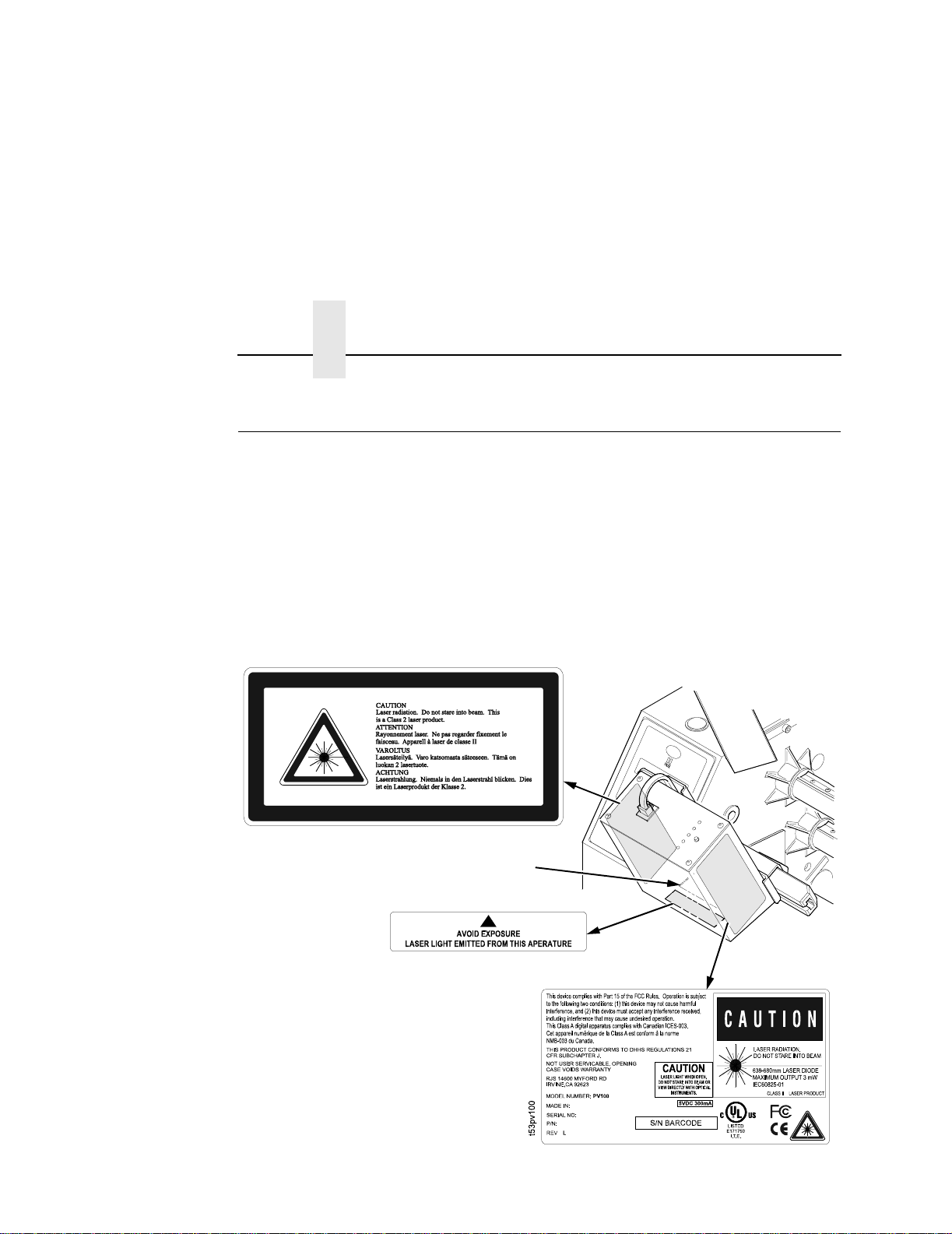
The validator is a Class 2 laser product. The following notices apply
at all times when the printer is powered on and the validator is
active:
WARNING
WARNING
Note: This is the laser exit window.
Class 2 laser light. Do not stare into the laser beam or a
reflected image of the laser beam.
Using controls, making adjustments, or performing
procedures other than those specified herein may result in
hazardous radiation exposure.
14
Figure 1. Safety Warnings

Installa tion and Removal
This section describes how to install the validator. To remove the
validator, reverse the steps of this procedure.
Prepare The Printer
1. Set the printer power switch to O (Off).
Prepare The Printer
WARNING
Always unplug the printer power cord from the printer or
power outlet before doing any installation procedure. Failure
to remove power could result in injury to you and damage the
equipment. You will be instructed when to apply power.
2. Unplug the printer power cord from the printer or the AC power
source.
Factory Installation
If your printer has a factory installed validator, the ferrite, cable, wire
saddle, and grommet have already been installed. Go to “Install
The Brackets” on page 22.
Field Installation
If you are doing a field installation, you must install the ferrite, cable,
wire saddle, and grommet. Go to “Install The Ferrite” on page 16.
15
Chapter 1 Installation and Removal
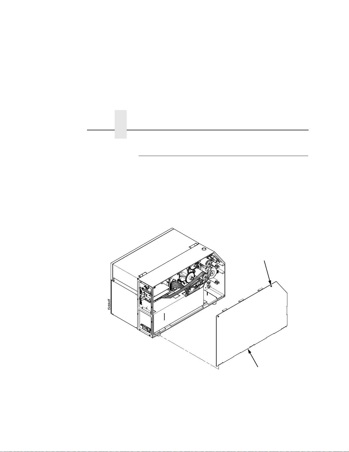
Install The Ferrite
1. Loosen the two captive screws securing the top of the frame
side cover. (Figure 2.)
2. Tilt the frame side cover back from the top and lift it until the
tabs along the lower edge disengage from the slots in the
printer frame.
Captive Screw (2)
16
Frame Side Cover
Figure 2. Removing the Frame Side Cover

Install The Ferrite
RJ-11 Connector
(to validator)
Figure 3. Wrapping the Power/Data Cable Around the Ferrite
Power/Data Cable
Second Wrap
20.0 ± 0.5
inches
Power/Data Cable
First Wrap
Ferrite
Wide P10 Connect or
(to controller board)
3. Using the RJ-11 connector end of the power/data cable, insert
the cable through the ferrite. (Figure 3.)
4. Wrap the power/data cable around the ferrite twice.
5. Adjust the position of the ferrite so that the length from the
ferrite to the RJ-11 connector is 20 ± 0.5 in
ches.
17

Chapter 1 Installation and Removal
Wire Saddle
Frame Boss
18
Figure 4. Inserting the Wire Saddle Into the Frame Boss
6. Insert the wire saddle into the frame boss. (Figure 4.)
Install The Ferrite
Ferrite
Wire Saddle
RJ-11 Connector
(to validator)
Frame
Opening
Figure 5. Inserting the Power/Data Cable Through the Hole in the Frame Wall
7. Raise the media cover and remove the solid grommet from the
frame opening.
8. On the electronics side of the printer, push the RJ-11 connector
end of the power/data cable through the frame opening.
(Figure 5.)
9. Route the power/data cable through the wire saddle.
19

Chapter 1 Installation and Removal
Split
Grommet
RJ-11
Connector
Power/Data Cable
(approximately
17 inches exposed)
Inserted Split
Grommet
(media side)
20
Figure 6. Adding the Grommet to the Power/Data Cable
10. On the media side of the printer, slide the split grommet onto
the power/data cable and insert it into the frame opening.
(Figure 6.)
11. Inspect the power/data cable to ensure approximately
17 inches of cable is exposed from the grommet to connect it to
the validator.
NOTE: You will plug the power/data cable into the validator later.
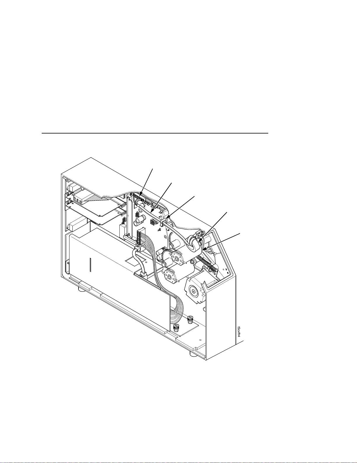
J10
Power/Data Cable
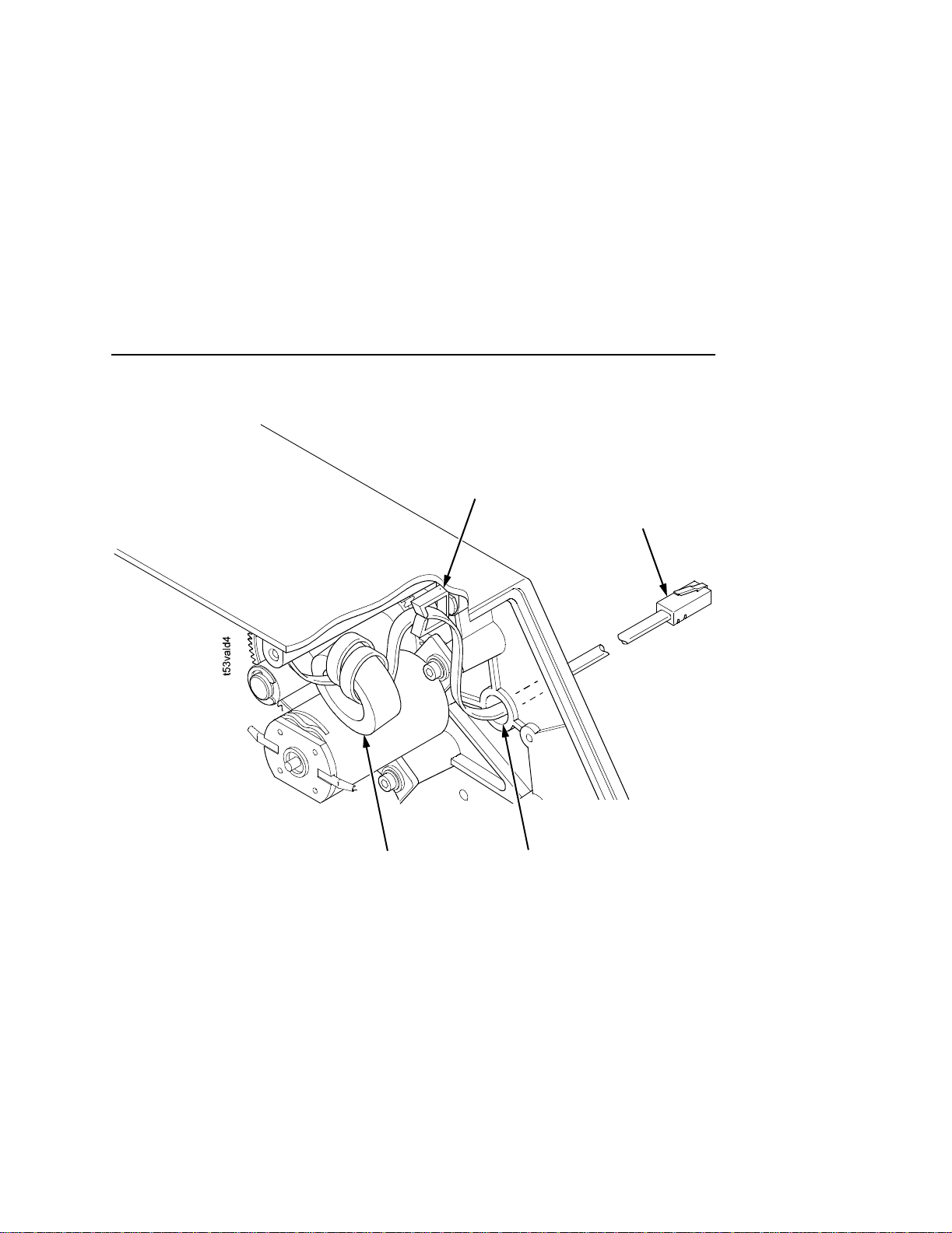
Install The Ferrite
Wire Saddle
Ferrite
Upper
DC Motor
Figure 7. Position the Ferrite
12. On the electronics side of the printer, position the ferrite on top
of the upper DC motor. (Figure 7.)
13. Route the power/data cable through the wire saddle as shown
in Figure 7.
14. Plug the wide P10 connector end of the power/data cable into
the J10 receptacle on the controller board.
21
Chapter 1 Installation and Removal
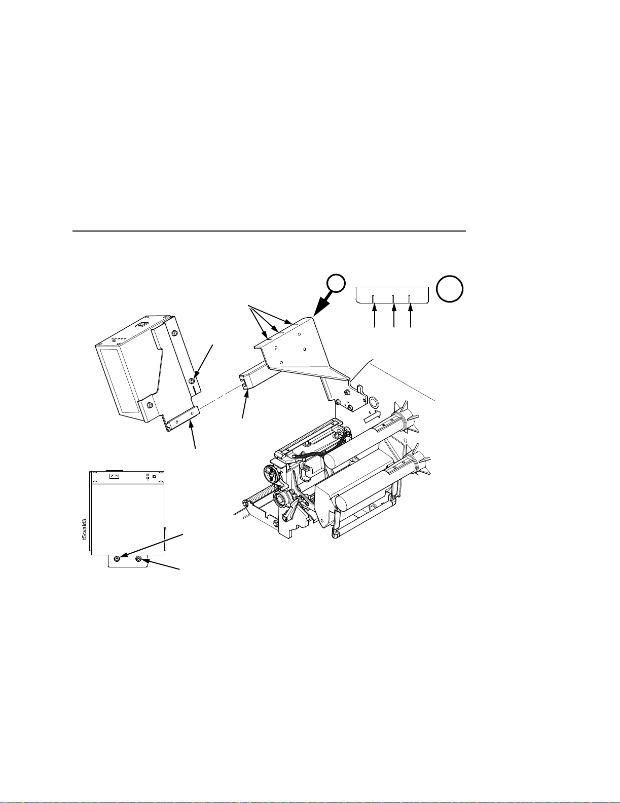
Install The Brackets
22
Lower
Bracket
M4x10mm
Screw (3)
Figure 8. Installing the Lower Bracket
1. Using three of the four M4x10mm screws, install the lower
bracket as shown in Figure 8.
NOTE: You will use the fourth screw later in this procedure.
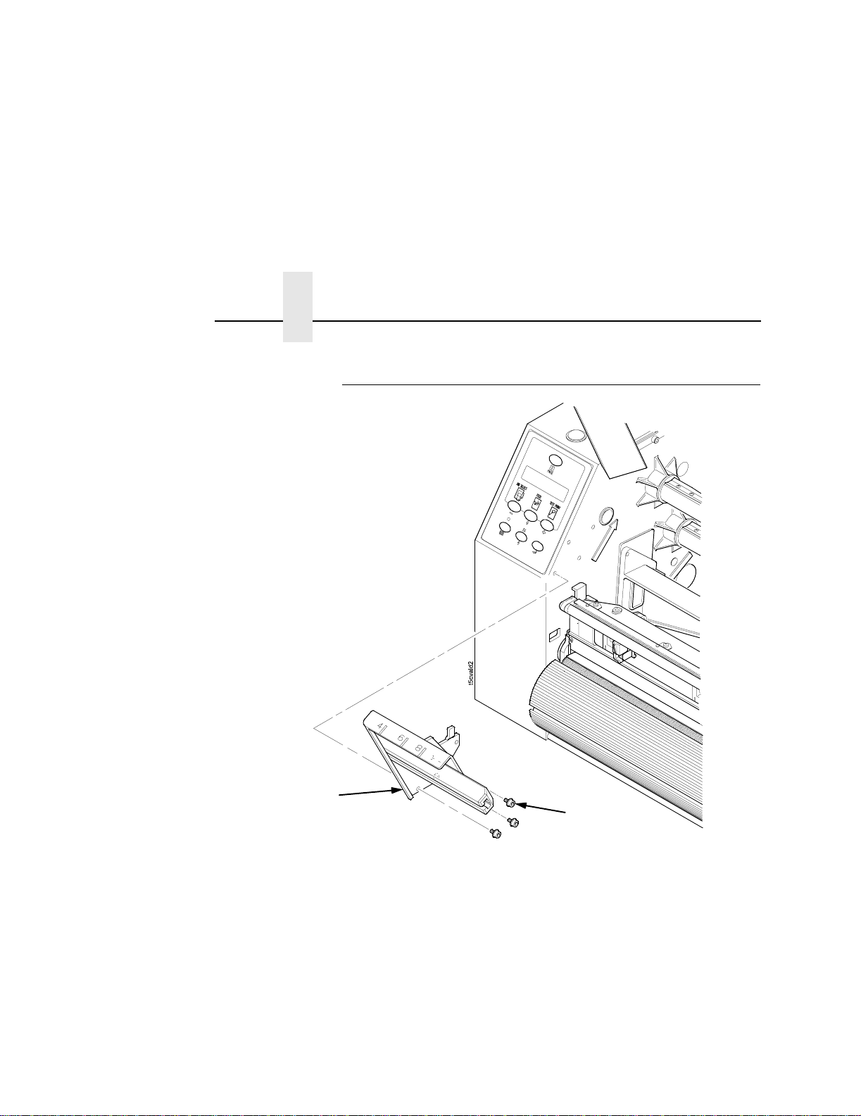
Install The Brackets
A
4 in.
6 in. 8 in.
Printer
Validator
(Rear View)
Validator
(Front View)
Hash
Marks
Alignment
Screw
Lower
Bracket
Upper
Bracket
Inside
Adjustment
Screw
Outside
Adjustment
Screw
Figure 9. Installing the Validator/Upper Bracket Unit onto the Lower Bracket
A
2. Face the front of the printer while installing the validator/upper
bracket unit.
3. Loosen the outside adjustment screw and remove the inside
adjustment screw on the bottom of the validator.
4. Slide the validator/upper bracket unit onto the lower bracket and
align the hash marks with the alignment screw accordingly.
NOTE: Refer to Figure 9, Detail A for location of the validator hash
mark for each printer model size. The printer model size is
also inscribed on the lower bracket.
5. When the unit is positioned correctly, tighten the outside
adjustment screw on the validator to lock the unit into place.
23
Chapter 1 Installation and Removal
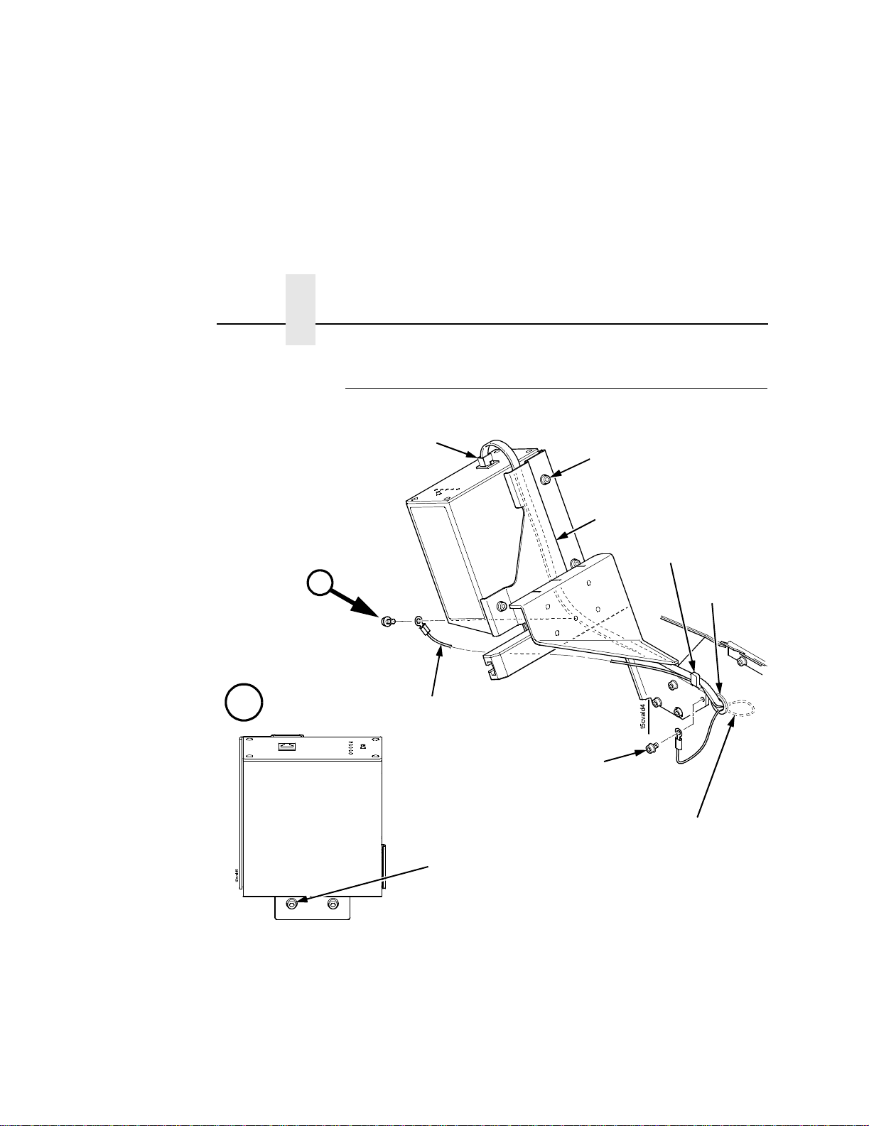
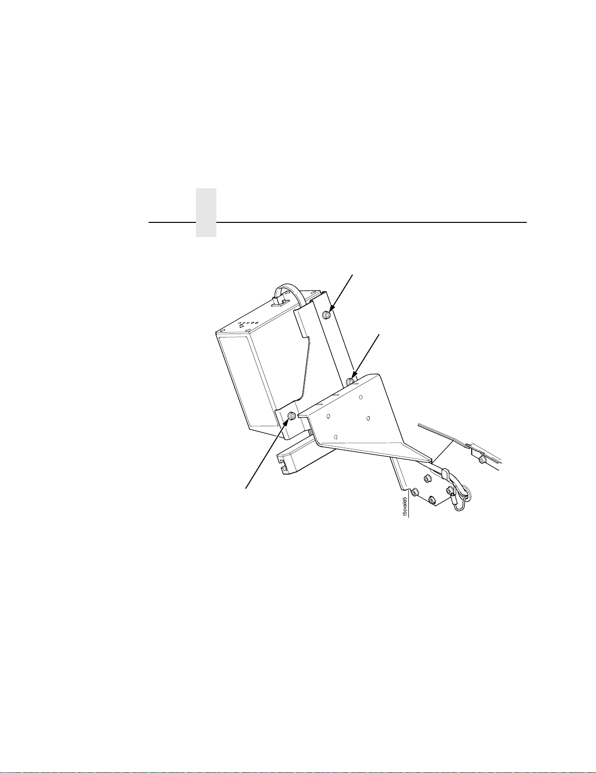
Attach The Grounding Wire And Power/Dat a Cable
Power/Data Cable
(Long Connector)
Upper Bracket
Screw (3)
Cable
Channel
Bracket Tab
A
A
Validator
(Front View)
Figure 10. Attaching the Grounding Wire and Power/Data Cable
1. Attach one end of the grounding wire to the validator using the
Grounding
Wire
Bracket Moun ting Screw
Grounding Wire
Slack
Inside
Adjustment
Screw
inside adjustment screw as shown in Figure 10.
Grommet
24
2. Attach the other end of the grounding wire to the lower bracket
using the fourth bracket mounting screw as shown in Figure 10.
3. Push any excess grounding wire slack through the grommet.

Attach The Grounding Wire And Power/Data Cable
4. Loosen the three upper bracket screws and route the
power/data cable through the cable channel in the upper
bracket, as shown in Figure 10.
5. Plug the RJ-11 connector end of the power/data cable into the
validator.
6. Route the power/data cable behind the bracket tab as shown in
Figure 10.
NOTE: If necessary, loosen the bracket mounting screws enough
to slip the power/data cable behind the bracket tab, then
retighten the bracket mounting screws.
7. Pull the cable to minimize the slack behind the lower bracket.
Push any excess slack through the grommet.
8. Tighten the three upper bracket screws.
Restore The Printer To Operation
1. Lower the media cover.
2. Engage the tabs on the bottom of the frame side cover in the
slots in the printer frame.
3. Rotate the cover into position.
4. Tighten the two captive screws. (Figure 2.)
5. Plug the AC power cord into the printer and the power source.
6. Set the printer power switch to | (On).
25

Chapter 1 Enable The Validator
Enable The V a lidator
NOTE: If you make any changes to the default configuration menu
items, you will be prompted to save the configuration.
See “Auto Save Configuration” in the
Software can automatically detect an installed validator when the
printer is powered up. If the printer is powered up with Power-Up
Config. set to Factory, the VALIDATOR menu will be available and
Validator Funct. is set to Enable in the QUICK SETUP and
VALIDATOR menus.
If Power-Up Config. is not set to Factory, the VALIDATOR menu
appears, but Validator Funct. is set to Disable. Enable Validator
Funct. by completing the following steps. (This is a one-time setting
once you save the configuration.)
.
1. Press to take the printer offline and place the printer in
Menu mode.
.
.
Quick Setup Guide
.
26
2. If necessary, press ↓ and
↵ at the same time to unlock the
↵ key. (This key combination can be changed by the user. Use
the customer’s key combination if necessary.)
.
3. If necessary, press until VALIDATOR displays.
4. Press ↓ until Validator Funct. displays.
5. Press + or – until the Enable displays.
6. Press
7. Press ↓ and
8. Press PAUSE again to put the printer online.
↵ to enable the validator. An asterisk (*) should appear
after Enable. Once enabled, the printer will command the
validator to begin scanning and reporting errors, and the
counters will be incremented.
↵ at the same time to lock the ↵ key, then press
PAUSE to take the printer offline.
.
.
Adjust The Scanning Beam
,
NOTE: Make sure the printer is on and the scanning beam is on. If
the beam is off, press the RESET button for less than 2
seconds to turn on the beam.
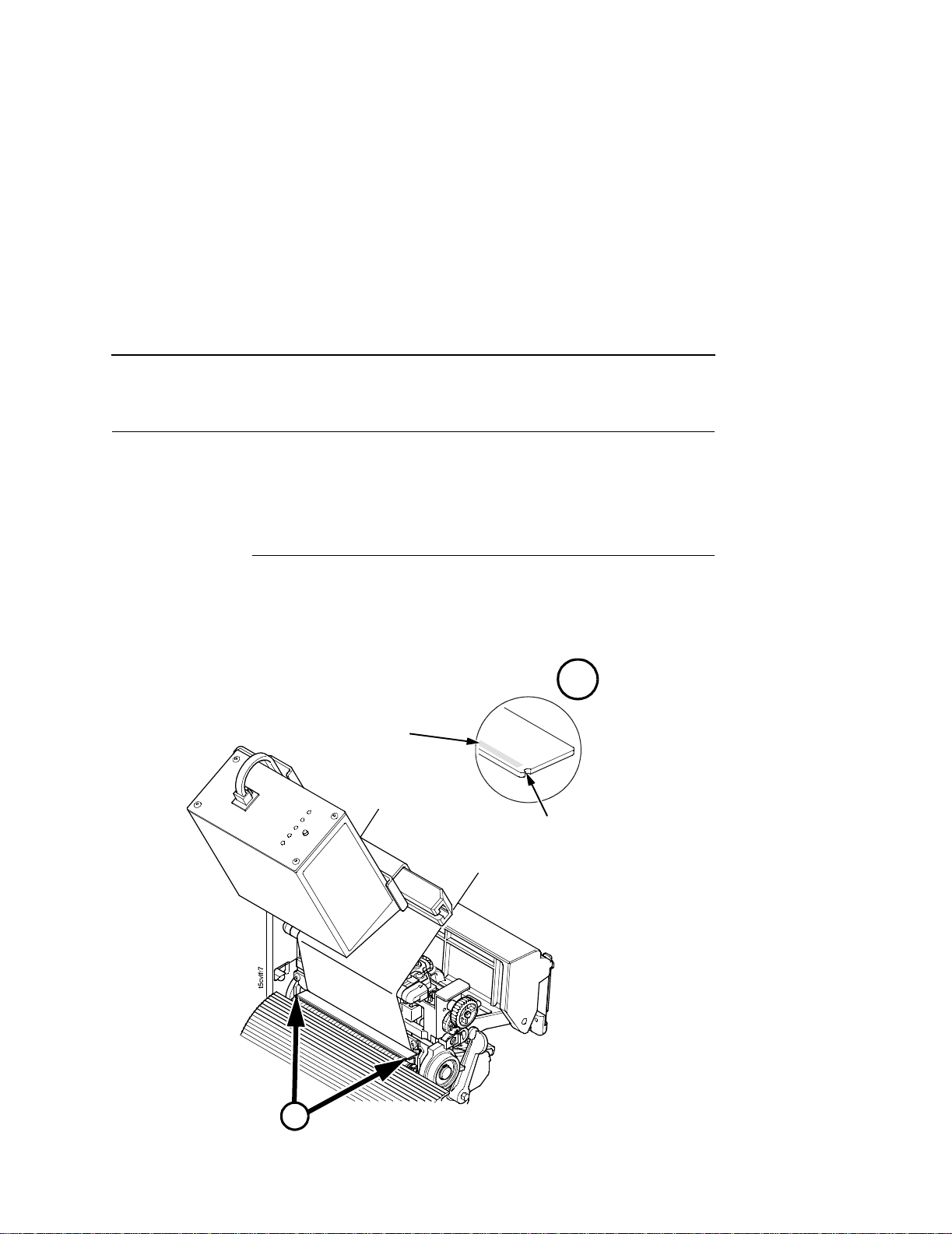
Continuous, Tear- Off, and Tear-Off Strip
When the validator is first installed, the scanning beam may need to
be aligned with the two notches on the sides of the tear bar, as
shown in Detail A of Figure 11. When the scanning beam is
properly aligned it will line up with the two notches.
Scanning Beam
Continuous, Tear-Off, and Tear-Off Strip
A
Notch in Tear Bar
t5lsrlc2
Ju ne 19
2000
A
Figure 11. Aligning the Scanning Beam: Continuous, Tear-Off, and Tear-Off Strip
Media Handling Modes Only
27
Chapter 1 Adjust The Scanning Beam
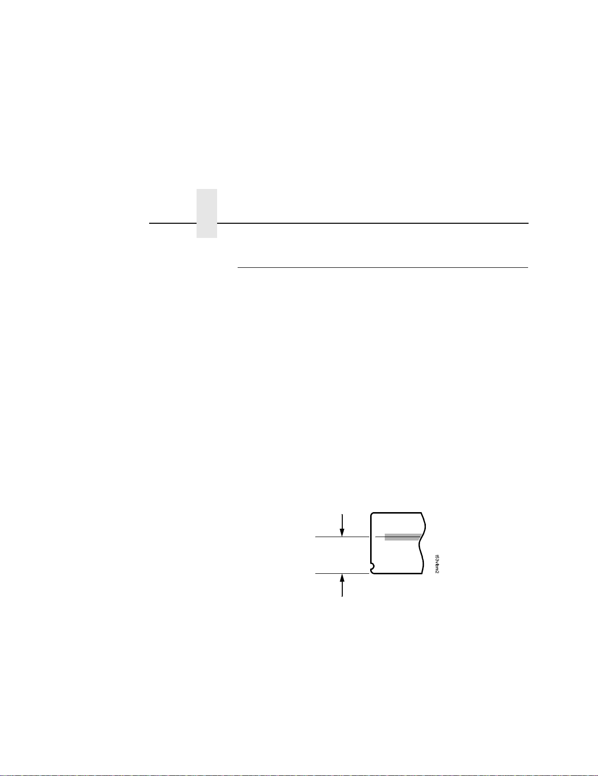
Peel-Off Media Handling Mode
If your printer is configured for Peel-Off Media Handling mode (use
of optional internal rewinder), you may need to align the beam
further behind the notches (0.20 to 0.30 inches [5.08 mm to
7.62 mm] from the front edge of the tear bar) so that the peeled
label remains on the tear bar and the trailing edge of the last bar
code can still pass completely under the scanning beam. See
Figure 12.
Aligning the scanning beam to any position other than the notches
on the tear bar should only be done if the last printed bar code
image does not clear the beam when the label is at the peel-off
position after printing. In addition, the distance the beam moves
back from the tear bar edge must correspond to a distance from the
leading edge of the label that does not have bar code printing. For
example, aligning the beam 0.20 inches from the front edge of the
tear bar requires that 0.20 inches of the leading edge of the label
must not have bar code images.
0.30 inches
(7.62 mm)
Figure 12. Aligning the Scanning Beam: Peel-Off Media Handling Mode Only
28

Cut Media Handling Mode
Cut Media Handling Mode
If your printer has a cutter installed and is configured for Cut Media
Handling Mode, align the beam with the notches at each side of the
opening on the hinged upper lid, as shown in Detail A of Figure 13.
Scanning Beam
A
Notch in Tear Bar/
Figure 13. Aligning the Scanning Beam: Cutter Installed
A
Cutter
29
Chapter 1 Adjust The Scanning Beam
Top Left Screw
Bottom Right Screw
Bottom Left Screw
30
Figure 14. Scanning Beam Adjustment Screws
Figure 14 shows the screws used to adjust the parallelism and
position of the scanning beam. The positions of the screws assume
that you are in front of the validator unit and facing the printer. The
following instructions and illustrations show how to adjust the
validator according to how the beam appears.
1. Power the printer on and make sure the scanning beam is on. If
the beam is off, press the RESET button for less than 2
seconds to turn on the scanning beam.
2. Use the Allen key provided to adjust the screws.
NOTE: You may have to loosen all three screws and allow the
rubber spacers to expand (relax) before making any
adjustments.
Loading...