


 Loading...
Printronix P5214-SS, P52KA, P5214, P5215, P5210 User Manual
...®
Maintenance Manual
The Printronix P5000 series of Line Matrix Printers

The Printronix P5000 series of Line Matrix Printers
Maintenance Manual
®
164253-001, Rev D

Trademark Acknowledgements
Trademark Acknowledgements
ANSI is a registered trademark of American National Standards Institute, Inc. Centronics is a registered trademark of Genicom Corporation.
Code V is a trademark of Quality Micro Systems. Chatillon is a trademark of John Chatillon & Sons, Inc.
Dataproducts is a registered trademark of Dataproducts Corporation. EIA is a registered service mark of Electronic Industries Association. ENERGY STAR® is a registered trademark of the United States Environmental Protection Agency. As an ENERGY STAR® Partner, Printronix has determined that this product meets the ENERGY STAR® guidelines for energy efficiency.
Ethernet is a trademark of Xerox Corporation.
IBM is a registered trademark of International Business Machines Corporation.
IEEE is a registered trademark of the Institute of Electrical and Electronics Engineers.
IGP is a registered trademark of Printronix, Inc.
Intelligent Printer Data Stream and IPDS are trademarks of International Business Machines Corporation.
LinePrinter Plus is a registered trademark of Printronix, Inc. MS-DOS is a registered trademark of Microsoft Corporation.
PC-DOS is a trademark of International Business Machines Corporation. PGL is a registered trademark of Printronix, Inc.
PrintNet is a trademark of Printronix, Inc.
Printronix is a registered trademark of Printronix, Inc. PSA is a trademark of Printronix, Inc.
QMS is a registered trademark of Quality Micro Systems. RibbonMinder is a trademark of Printronix, Inc.
SureStak is a trademark of Printronix, Inc.
Torx is a registered trademark of Camcar/Textron Inc. Utica is a registered trademark of Cooper Power Tools.
Warranty and Copyright Information
Printronix, Inc. makes no representations or warranties of any kind regarding this material, including, but not limited to, implied warranties of merchantability and fitness for a particular purpose. Printronix, Inc. shall not be held responsible for errors contained herein or any omissions from this material or for any damages, whether direct, indirect, incidental or consequential, in connection with the furnishing, distribution, performance or use of this material. The information in this manual is subject to change without notice.
This document contains proprietary information protected by copyright. No part of this document may be reproduced, copied, translated or incorporated in any other material in any form or by any means, whether manual, graphic, electronic, mechanical or otherwise, without the prior written consent of Printronix, Inc.
All rights reserved.
COPYRIGHT © 1996, 1999, PRINTRONIX, INC.

Warranty and Copyright Information
Communication Notices
Federal Communications Commission (FCC) Statement: This equipment has been tested and found to comply with the limits for a Class A digital device, pursuant to Part 15 of the FCC Rules. These limits are designed to provide reasonable protection against harmful interference when the equipment is operated in a commercial environment. This equipment generates, uses, and can radiate radio frequency energy and, if not installed and used in accordance with the instruction manual, may cause harmful interference to radio communications. Operation of this equipment in a residential area is likely to cause harmful interference, in which case the user will be required to correct the interference at his own expense.
Properly shielded and grounded cables and connectors must be used in order to meet FCC emission limits. Printronix is not responsible for any radio or television interference caused by using other than recommended cables and connectors or by unauthorized changes or modifications to this equipment. Unauthorized changes or modifications could void the user’s authority to operate the equipment.
This device complies with Part 15 of the FCC Rules. Operation is subject to the following two conditions: (1) this device may not cause harmful interference, and (2) this device must accept any interference received, including interference that may cause undesired operation.
Canadian Department of Communications Compliance Statement:
This Class A digital apparatus meets all requirements of the Canadian
Interference-Causing Equipment Regulations.
Avis de conformité aux normes du ministère des Communications du
Canada:
Cet appareil numérique de la classe A respecte toutes les exigences du
Règlement sur le matériel brouilleur du Canada.
European Union (EC) Electromagnetic Compatibility Directives: This product is in conformity with the protection requirements of EC Council Directive 89/336/EEC on the approximation of the laws of the Member States relating to electromagnetic compatibility. Printronix cannot accept responsibility for any failure to satisfy the protection requirements resulting from a non-recommended modification of the product, including the fitting of non-Printronix option cards.
Dieses Gerät ist berechtigt in Übereinstimmung mit dem deutschen EMVG vom 9.Nov.92 das EG-Konformitätszeichen zu furhren.
Properly shielded and grounded cables and connectors must be used in order to reduce the potential for causing interference to radio and TV communication and to other electrical or electronic equipment.
This product has been tested and found to comply with limits for Class A Information Technology Equipment according to CISPR 22/European Standard EN 55022. The limits for Class A equipment were derived for commercial and industrial environments to provide reasonable protection against interference with licensed communication equipment.
Chapter Communication Notices
Warning: This is a Class A product. In a domestic environment this product may cause radio interference in which case the user may be required to take adequate measures.
Dieses Gerät erfüllt die Bedingungen der EN 55022 Klasse A. Für diese Klasse von Geräten gilt folgende Bestimmung nach dem EMVG:
Geräte dürfen an Orten, für die sie nicht ausreichend entstört sind, nur mit besonderer Genehmigung des Bundesminesters für Post und Telekommunikation oder des Bundesamtes für Post und Telekommunikation betrieben werden. Die Genehmigung wird erteilt, wenn keine elektromagnetischen Störungen zu erwarten sind.
(Auszug aus dem EMVG vom 9.Nov.92, Para.3, Abs.4)
Hinweis: Dieses Genehmigungsverfahren ist von der Deutschen Bundespost noch nicht veröffentlict worden.
6

Table of Contents
1 |
Maintenance Overview......................... |
11 |
|
About the Printer................................................................. |
11 |
|
P5000 Printers .................................................................... |
11 |
|
Kanji/Hanzi Printers...................................................... |
11 |
|
Printer Evolution........................................................... |
12 |
|
How to Identify the Printer ............................................ |
12 |
|
Important Maintenance Notes............................................. |
15 |
|
About This Manual.............................................................. |
15 |
|
How to Use This Manual .............................................. |
16 |
|
Notes and Notices ........................................................ |
16 |
|
Printing Conventions in This Manual............................ |
16 |
|
Safety Notices..................................................................... |
17 |
|
Hinweise zur Sicherheit ...................................................... |
17 |
|
Controls and Indicators....................................................... |
18 |
|
Tools, Test Equipment, and Supplies ................................. |
24 |
2 |
Preventive Maintenance....................... |
25 |
|
Cleaning the Printer ............................................................ |
25 |
|
Cleaning the Outside Surfaces ........................................... |
25 |
|
Cleaning the Shuttle Frame Assembly ............................... |
27 |
|
Cleaning the Card Cage Fan Assembly ............................. |
28 |
3 |
Troubleshooting ................................... |
29 |
|
Introduction ......................................................................... |
29 |
|
Troubleshooting Aids .......................................................... |
29 |
|
Start Here... ........................................................................ |
30 |
|
Troubleshooting Display Messages.................................... |
31 |
|
How to Clear LCD Messages ....................................... |
31 |
|
Troubleshooting Other Symptoms ...................................... |
36 |
|
Troubleshooting Procedures............................................... |
38 |
|
How to Use the Troubleshooting Procedures............... |
38 |
|
The Procedures............................................................ |
39 |
|
Communications Failures ................................................... |
88 |
|
Diagnostic Printer Tests...................................................... |
89 |
|
Selecting and Running Diagnostic Printer Tests .......... |
90 |
|
Boot Diagnostics Menu....................................................... |
92 |
vii

Table of Contents
|
Hex Code Printout .............................................................. |
95 |
|
How to Print a Hex Dump............................................. |
96 |
|
ASCII Character Set ........................................................... |
97 |
|
Soft vs. Hard Reset............................................................. |
98 |
|
The Power On Sequence ................................................... |
99 |
|
CMX Controller Board Handshake Sequences............ |
99 |
|
DC Software Initialization and Power Up ................... |
103 |
4 |
Adjustment Procedures ..................... |
105 |
|
Introduction ....................................................................... |
105 |
|
Preparing the Printer for Maintenance.............................. |
106 |
|
Returning the Printer to Normal Operation ....................... |
107 |
|
Belt, Paper Feed Timing, Adjustment (Figure 10) ............ |
108 |
|
Belt, Platen Open, Adjustment (Figure 11) ....................... |
110 |
|
Paper Drive Motor Pulley Alignment (Figure 12) .............. |
112 |
|
Paper Scale Alignment (Figure 13)................................... |
114 |
|
Platen Gap Adjustment (Figure 14) .................................. |
116 |
|
Platen Open Motor Pulley Alignment (Figure 15) ............. |
118 |
|
Ribbon Guide Alignment (Figure 16) ................................ |
120 |
|
Splined Shaft Skew Adjustment (Figure 17) ..................... |
122 |
|
Paper Out Adjustment ...................................................... |
124 |
|
Hammer Phasing Adjustment ........................................... |
128 |
|
Loading Flash Memory from One Diskette ....................... |
130 |
|
Loading Flash Memory from Multiple Diskettes................ |
135 |
|
Set Shuttle Speed............................................................. |
141 |
5 |
Replacement Procedures |
|
and Illustrated Parts Lists ....................... |
143 |
|
|
Organization of This Chapter............................................ |
143 |
|
Section I: Replacement Procedures ................................. |
144 |
|
List of Removal/Installation Procedures ..................... |
144 |
|
Belt, Paper Feed Timing ............................................ |
146 |
|
Belt, Platen Open ....................................................... |
147 |
|
Circuit Breaker ........................................................... |
148 |
|
Connector Shells........................................................ |
149 |
|
Connector Stiffening Clips.......................................... |
151 |
|
Control Panel Assembly, Cabinet Models.................. |
153 |
|
Control Panel Assembly, Pedestal Models ................ |
154 |
|
Controller Board (CMX).............................................. |
155 |
|
Cover Assembly, Hammer Bank / Ribbon Mask ........ |
157 |
|
Cover Assembly, Shuttle............................................ |
160 |
|
Cover Assembly, Top, Pedestal Models .................... |
161 |
viii

Table of Contents
Expansion-CT ............................................................ |
162 |
Fan Assembly, Cabinet Exhaust ................................ |
163 |
Fan Assembly, Card Cage ......................................... |
164 |
Fan Assembly, Hammer Bank.................................... |
165 |
Hammer Spring Assembly.......................................... |
166 |
Magnetic Pickup (MPU) Assembly ............................. |
170 |
Memory Modules and Security PAL ........................... |
171 |
Paper Feed Motor ...................................................... |
174 |
Paper Ironer ............................................................... |
176 |
Paper Path ................................................................. |
177 |
Platen ......................................................................... |
178 |
Platen Open Motor ..................................................... |
182 |
Power Supply Board .................................................. |
184 |
PrintNet Ethernet Interface Assemblies ..................... |
185 |
10Base2 and 10Base-T LEDs and DIP Switches ...... |
186 |
10/100Base-T LEDs and Dipswitches........................ |
188 |
Resistors, Terminating ............................................... |
190 |
Ribbon Drive Motor .................................................... |
192 |
Ribbon Guide Assembly (L/R).................................... |
193 |
Ribbon Hub ................................................................ |
194 |
Shaft, Splined............................................................. |
195 |
Shaft, Support ............................................................ |
197 |
Shuttle Frame Assembly ............................................ |
198 |
Spring Assembly, Gas................................................ |
200 |
Spring, Extension, Hammer Bank .............................. |
201 |
Switch Assembly, Paper Detector .............................. |
202 |
Switch Assembly, Platen Interlock ............................. |
203 |
Tractor (L/R) ............................................................... |
204 |
Section II: Illustrated Parts Lists ....................................... |
205 |
Illustrations of Printer Components ............................ |
205 |
6 Principles of Operation ...................... |
239 |
Line Matrix Printing ........................................................... |
239 |
Printing Rates ................................................................... |
242 |
Printing Mechanism .......................................................... |
242 |
Shuttle Frame Assembly ............................................ |
243 |
Paper Transport System ............................................ |
245 |
Ribbon Transport System........................................... |
246 |
Logical Control of the Printer ............................................ |
247 |
Control Panel .................................................................... |
248 |
CMX Controller Board....................................................... |
249 |
Data Controller ........................................................... |
251 |
ix

Table of Contents
|
Engine Controller ....................................................... |
254 |
|
Power Supply Board ......................................................... |
255 |
|
AC Power ................................................................... |
255 |
|
DC Power................................................................... |
256 |
|
Printer Interface ................................................................ |
256 |
|
Graphics ........................................................................... |
257 |
A |
Wire Data............................................. |
259 |
B |
Abbreviations & |
|
Signal Mnemonics ................................... |
299 |
|
C |
Metric Conversion Tables ................. |
307 |
D |
Noise Suppression Devices .............. |
309 |
E |
SureStak™ Power Stacker ................ |
311 |
|
Contents ........................................................................... |
311 |
|
Introduction ....................................................................... |
311 |
|
Removing the Power Stacker ........................................... |
312 |
|
Installing the Power Stacker ............................................. |
317 |
|
Replacing the Constant Force Spring............................... |
328 |
|
Replacing the Timing Belts ............................................... |
331 |
|
Illustrated Parts Breakdown.............................................. |
335 |
x
1 Maintenance Overview
About the Printer
Printronixâ P5000 series line matrix printers use PSAä (Printronix System Architecture), which puts all data control and printer control logic on one circuit board. The use of flash memory on this board permits rapid access to stored printer emulations and fast processing of print data. A variable-speed shuttle and half-step paper control enable these printers to print a wide variety of high-volume jobs with minimum maintenance and maximum reliability.
Although technologically advanced, the P5000 printer is easy to use. The operator can select every printer function at the printer control panel or by sending control codes in the data stream from the host computer to the printer. For greater security and to protect special printer configurations, the operator can program which key combination locks and unlocks the ENTER key on the control panel.
This is also an excellent graphics printer, with optional features that simplify the creation of images. The IGPâ and Code Vä Printronix emulations, for example, are simple but versatile graphics programming languages that load into flash memory.
P5000 Printers
The P5000 family consists of machines that print at different speeds. (See Table 1.) Many models are available in either a floor cabinet or pedestal housing. P5XKA (Kanji/Hanzi) models are available in pedestal, cabinet, or “table top” configuration. Despite its name, the table top P5XKA printer is not intended for use on a table. It is really a pedestal model printer that has been removed from the pedestal and packaged separately to facilitate shipping to certain international markets. A “table top” printer is then installed on its pedestal after it arrives at its destination.
Kanji/Hanzi Printers
P5XKA printers have shuttle assemblies, hammer springs, and software modified to print the Kanji/Hanzi character sets used in Asia. These printers support the GB Song and GB Kai character sets used in the People’s Republic of China, Singapore, and Hong Kong, and the Big-5 Ming character set used in Hong Kong and Taiwan. P5XKA printers can mix ASCII and Kanji/ Hanzi characters on the same line, with ASCII characters occupying half the width of Kanji/Hanzi character cells. Because of the density and complexity of these character sets, these models print at lower speeds.
11
Chapter 1 P5000 Printers
Printer Evolution
The newest models in the family are the P5X05B, P5X10, and P5X15, which are available both in pedestal and floor cabinet housings. These models have a redesigned shuttle frame assembly, hammer bank, and ribbon guides. The new shuttle and hammer bank assemblies are not compatible with earlier P5000 printers, but the new ribbon guides can be used on any model P5000 printer.
The P5X05B, P5X10, and P5X15 models also use the CMX 040 controller board, which has a 40 MHz clock speed for the Data Controller unit. The CMX 040 can be used in any P5000 printer, but the P5X05B, P5X10, and P5X15 models cannot use earlier versions of the CMX board.
When you replace components, be careful to order the correct spares for the model you are servicing. The next section explains how to identify a P5000 series printer.
How to Identify the Printer
A P5000 printer is identified by its model number. The model number is a code that indicates the printer type, family, speed, and housing. Figure 1 shows how to interpret a model number.
Table 1 lists the models comprising the P5000 family. The speeds listed in Table 1 are the highest speeds attainable under controlled conditions. Actual printing speed is determined by the interaction of many variables. For more information about printing speeds, refer to “Printing Rates” on page 242.
|
Housing Code: |
|
|
0 |
= Pedestal |
Printronix Line |
1 |
= Table Top |
2 |
= Floor Cabinet |
|
Matrix Printer |
|
|
Optional 12 MIL (0.012 inch) hammer tips. Standard tips are 16 MIL (0.016 inch). This option does not apply to Kanji/ Hanzi printers, which have unique hammer spring assemblies.
P5005-12-QA
P5000 Printer |
|
QA = Pedestal model with optional Quick- |
|
|
|
|
|
Access Cover |
Speed Rating: |
SS = Cabinet model with optional SureStak™ |
|
power paper stacker. |
||
05 |
= 475 lpm |
|
05A = 500 lpm |
|
|
05B = 500 lpm (40 MHz CMX board) |
||
08 |
= 800 lpm |
|
09 |
= 900 lpm |
|
10 |
= 1000 lpm |
|
12 |
= 1200 lpm |
|
14 |
= 1400 lpm |
|
15 |
= 1500 lpm |
|
KA = Kanji/Hanzi printer
Figure 1. How to Interpret Model Numbers
12

How to Identify the Printer
Table 1. P5000 Printers
|
|
|
Data |
||
Model Number |
Enclosure |
Hammer Bank |
Controller |
||
Speed |
|||||
|
|
|
Clock Speed1 |
||
|
|
|
|
||
|
|
|
|
|
|
P50KAä |
585 lpm |
Pedestal |
91 Hammers |
25 MHz |
|
|
|
|
Kanji / Hanzi |
|
|
|
|
|
|
|
|
P5005ä |
475 lpm |
Pedestal |
28 Hammers |
25 MHz |
|
|
|
|
|
|
|
P5005-QAä |
475 lpm |
Pedestal w/Quick- |
28 Hammers |
25 MHz |
|
|
|
Access Cover |
|
|
|
|
|
|
|
|
|
P5005-12ä |
475 lpm |
Pedestal |
28 Hammers, |
25 MHz |
|
|
|
|
12 MIL tips |
|
|
|
|
|
|
|
|
P5005-12-QAä |
475 lpm |
Pedestal w/Quick- |
28 Hammers, |
25 MHz |
|
|
|
Access Cover |
12 MIL tips |
|
|
|
|
|
|
|
|
P51KAä |
585 lpm |
Table Top |
91 Hammers |
25 MHz |
|
|
|
|
Kanji / Hanzi |
|
|
|
|
|
|
|
|
P5205ä |
475 lpm |
Cabinet |
28 Hammers |
25 MHz |
|
|
|
|
|
|
|
P5205-12ä |
475 lpm |
Cabinet |
28 Hammers, |
25 MHz |
|
|
|
|
12 MIL tips |
|
|
|
|
|
|
|
|
P5005Aä |
500 lpm |
Pedestal |
28 Hammers |
25 MHz |
|
|
|
|
|
|
|
P5005A-QAä |
500 lpm |
Pedestal w/Quick- |
28 Hammers |
25 MHz |
|
|
|
Access Cover |
|
|
|
|
|
|
|
|
|
P5005A-12ä |
500 lpm |
Pedestal |
28 Hammers, |
25 MHz |
|
|
|
|
12 MIL tips |
|
|
|
|
|
|
|
|
P5005A-12-QAä |
500 lpm |
Pedestal w/Quick- |
28 Hammers, |
25 MHz |
|
|
|
Access Cover |
12 MIL tips |
|
|
|
|
|
|
|
|
P5205Aä |
500 lpm |
Cabinet |
28 Hammers |
25 MHz |
|
|
|
|
|
|
|
P5205A-12ä |
500 lpm |
Cabinet |
28 Hammers, |
25 MHz |
|
|
|
|
12 MIL tips |
|
|
|
|
|
|
|
|
P5005Bä |
500 lpm |
Pedestal |
28 Hammers |
40 MHz |
|
|
|
|
|
|
|
P5005B-QAä |
500 lpm |
Pedestal w/Quick- |
28 Hammers |
40 MHz |
|
|
|
Access Cover |
|
|
|
|
|
|
|
|
|
P5005B-12ä |
500 lpm |
Pedestal |
28 Hammers, |
40 MHz |
|
|
|
|
12 MIL tips |
|
|
|
|
|
|
|
|
P5005B-12-QAä |
500 lpm |
Pedestal w/Quick- |
28 Hammers, |
40 MHz |
|
|
|
Access Cover |
12 MIL tips |
|
|
|
|
|
|
|
|
P5205Bä |
500 lpm |
Cabinet |
28 Hammers |
40 MHz |
|
|
|
|
|
|
13

Chapter 1 P5000 Printers
Table 1. P5000 Printers
|
|
|
Data |
||
Model Number |
Enclosure |
Hammer Bank |
Controller |
||
Speed |
|||||
|
|
|
Clock Speed1 |
||
|
|
|
|
||
|
|
|
|
|
|
P5205B-12ä |
500 lpm |
Cabinet |
49 Hammers, |
40 MHz |
|
|
|
|
12 MIL tips |
|
|
|
|
|
|
|
|
P5008ä |
800 lpm |
Pedestal |
49 Hammers |
25 MHz |
|
|
|
|
|
|
|
P5008-QAä |
800 lpm |
Pedestal w/Quick- |
49 Hammers |
25 MHz |
|
|
|
Access Cover |
|
|
|
|
|
|
|
|
|
P5208ä |
800 lpm |
Cabinet |
49 Hammers |
25 MHz |
|
|
|
|
|
|
|
P500ä |
900 lpm |
Pedestal |
49 Hammers |
25 MHz |
|
|
|
|
|
|
|
P5009-QAä |
900 lpm |
Pedestal w/Quick- |
49 Hammers |
25 MHz |
|
|
|
Access Cover |
|
|
|
|
|
|
|
|
|
P5209ä |
900 lpm |
Cabinet |
49 Hammers |
25 MHz |
|
|
|
|
|
|
|
P5010ä |
1000 lpm |
Pedestal |
60 Hammers |
40 MHz |
|
|
|
|
|
|
|
P5010-QAä |
1000 lpm |
Pedestal w/Quick- |
60 Hammers |
40 MHz |
|
|
|
Access Cover |
|
|
|
|
|
|
|
|
|
P5210ä |
1000 lpm |
Cabinet |
60 Hammers |
40 MHz |
|
|
|
|
|
|
|
P5212ä |
1200 lpm |
Cabinet |
91 Hammers |
25 MHz |
|
|
|
|
|
|
|
P5214ä |
1400 lpm |
Cabinet |
91 Hammers |
40 MHz |
|
|
|
|
|
|
|
P5214-SSä |
1400 lpm |
Cabinet |
91 Hammers |
40 MHz |
|
|
|
w/SureStak |
|
|
|
|
|
Paper Stacker |
|
|
|
|
|
|
|
|
|
P5015ä |
1500 lpm |
Pedestal |
102 Hammers |
40 MHz |
|
|
|
|
|
|
|
P5015-QAä |
1500 lpm |
Pedestal w/Quick- |
102 Hammers |
40 MHz |
|
|
|
Access Cover |
|
|
|
|
|
|
|
|
|
P5215ä |
1500 lpm |
Cabinet |
102 Hammers |
40 MHz |
|
|
|
|
|
|
|
P5215-SSä |
1500 lpm |
Cabinet |
102 Hammers |
40 MHz |
|
|
|
w/SureStak |
|
|
|
|
|
Paper Stacker |
|
|
|
|
|
|
|
|
|
P52KAä |
585 lpm |
Cabinet |
91 Hammers |
40 MHz |
|
|
|
|
Kanji / Hanzi |
|
|
|
|
|
|
|
1 The microprocessor of the Data Controller unit on the CMX controller board runs at 25 MHz or 40 MHz, depending on printer model. This means there are two kinds of CMX controller board for these printers, used as indicated in Table 1. The 40 MHz controller board, however, is compatible with all models that use the 25 MHz board and should be used if the CMX board is replaced.
14

How to Identify the Printer
Important Maintenance Notes
To ensure the best performance of the printer, remember these maintenance principles whenever you service the printer.
CAUTION Failure to observe these guidelines can result in damage to the equipment.
•Do not adjust the platen gap unless
1)the original shuttle frame assembly or platen has been replaced with a new or rebuilt unit, or
2)you are instructed to do so in a troubleshooting procedure.
•Never bend or tweak hammer springs. Always handle hammer springs by the thick mounting base. The hammer springs and hammer tips are delicate and precisely aligned.
•Use only the ribbons specified in Appendix B. Use of incorrect ribbons can lead to ink migration problems, degraded print quality, and expensive damage to the printer.
•Do not close the forms thickness lever too tightly. Closing the forms thickness lever too tightly can lead to smearing, degraded print quality, paper jams, and damage to the platen and shuttle assembly.
About This Manual
This is a field service maintenance manual. It is designed so that you can locate maintenance information quickly.
This manual does not explain how to install, operate, or configure the printer. That information is in the User’s Manual.
This manual does not explain how to program application software for operation with the printer. Programming information for the protocols used by the printer is in the appropriate programmer’s reference manual:
•LinePrinter Plusâ Programmer’s Reference Manual
Defines host control codes for the LinePrinter Plus emulations.
•Character Sets Reference Manual
Information about and examples of the character sets available in Printronix line matrix printers.
•Network User’s Manual
Information about network protocols, configuration, and network operation.
•Coax/Twinax Programmer’s Reference Manual
Defines host control codes and character sets for the optional coax/twinax emulations.
•ANSIâ Programmer’s Reference Manual
Defines host control codes and character sets for the ANSI emulation.
•IPDSä Twinax Emulation Programmer’s Reference Manual
An overview of Intelligent Printer Data Stream™ (IPDS) features, commands, and diagnostics.
15

Chapter 1 About This Manual
•IGP/PGLâ Programmer’s Reference Manual
Describes the optional IGP Printronix emulation. The IGP Printronix emulation allows the user to create and store forms; generate logos, bar codes, and expanded characters; create other graphics, and merge graphics with alphanumeric data as a document is printed.
•IGP/VGL Programmer’s Manual
Describes the optional Code V Printronix emulation. The Code V Printronix emulation allows the user to create and store forms; generate logos, bar codes, and expanded characters; create other graphics, and merge graphics with alphanumeric data as a document is printed.
How to Use This Manual
1.Find the procedure or information you need in the Table of Contents or the Index.
2.Read the entire procedure before you work on the printer.
3.Gather the parts and tools you will need.
4.Make sure you understand all safety notices before you start a task. (See below.)
Notes and Notices
For your safety and to protect valuable equipment, read and comply with all information highlighted under notes and notices. The heading of a notice indicates the kind of information it contains:
WARNING Conditions that could hurt you and damage equipment.
CAUTION Conditions that could damage equipment.
IMPORTANT Information vital to proper operation and maintenance of the printer.
NOTE: Notes contain tips for efficient operation, maintenance, and troubleshooting.
IMPORTANT The Safety Notices on page 17 apply at all times when you are working on the printer. Please read them now.
Printing Conventions in This Manual
Control panel keys and indicators are highlighted in UPPERCASE BOLD PRINT.
Example: Press the CANCEL key, then press the ON LINE key.
LCD (Liquid Crystal Display) messages are set off by quotation marks (“ “). Example: Press the ON LINE key. “OFF LINE” appears on the LCD.
Control panel key combinations are indicated by the + (plus) symbol. Example: Press = + >.
means Press the =(UP) key and the >(DOWN) key at the same time.
16

Printing Conventions in This Manual
Safety Notices
WARNING Always disconnect the AC power cord from the printer or power source before performing any maintenance procedure. Failure to remove power could result in injury to persons or damage to equipment. If you must apply power during maintenance, you will be instructed to do so in the maintenance procedure.
WARNING Always disconnect the AC power cord before cleaning the printer.
WARNING To prevent injury from electric shock, wait at least one minute after shutting off power before removing the power supply circuit board. Wear a properly grounded static wrist strap when handling the power supply board. Handle the board by the sides. Do not touch components or flex the board during removal/installation.
WARNING Over time, the upper edge of the paper ironer can become sharp. To avoid cutting yourself, handle the paper ironer on the sides.
WARNING Hold the printer cover securely while disengaging the gas spring assembly.
Hinweise zur Sicherheit
VORSICHT
Bevor Sie anfällige Wartungsarbeiten durchführen, müssen Sie zuerst immer das Netzkabel aus der Steckdose ziehen. Wird das Netzkabel nicht herausgezogen, können Verletzungen oder Geräteschäden entstehen. Falls die Wartungsarbeit Stromzufuhr erfordert, wird im Wartungsablauf darauf hingewiesen.
VORSICHT
Ziehen Sie das Netzkabel aus der Steckdose, bevor Sie den Drucker reinigen.
VORSICHT
Um Verletzungen durch Elektroschocks zu vermeiden, warten Sie mindestens eine Minute nach Stromausschaltung, bevor Sie die elektrische Schaltkarte entfernen. Bitte immer einen geerdeten, statischen Handgelenkriemen tragen, wenn Sie die elektrische Schaltkarte handhaben. Halten Sie die Karte nur an den seitlichen Auswurfshebeln. Während des Herausnehmens/Installierens dürfen die Komponenten der Karte nicht berührt oder gebogen werden.
VORSICHT
Die obere Kante der Papierschiene wird mit der Zeit scharf. Halten Sie die Schiene deshalb an den Seiten, damit Sie sich nicht schneiden.
VORSICHT
Behalten Sie die Druckerabdeckung sicher im Griff, wenn Sie das
Gasfederpaket entfernen.
17

Chapter 1 Controls and Indicators
Controls and Indicators
Electrical Controls and Indicators, Cabinet Models (Figure 2)
Switch or |
Function |
Active |
Active |
|
Indicator |
On-line |
Off-line |
||
|
Power Switch |
Turns printer on and off: 1 = on, 0 = off. This switch is also a circuit breaker. |
Status |
On when the printer is on-line, off when the printer is off-line. Flashes to indicate a |
Indicator |
fault or warning. |
LCD |
Liquid Crystal Display. Displays printer status messages, fault messages, and |
|
menus which permit user to set various configurations. |
ON LINE/ |
Toggles the printer on-line and off-line. Clears the printer after a fault is corrected |
CLEAR |
and returns the printer to off-line state. |
PAPER |
Prints any data in the buffer then moves paper up one line at the currently active |
ADVANCE |
line spacing. If pressed longer than 1/2 second, moves paper to the next Top Of |
|
Form as defined by the currently active form length. |
VIEW /
EJECT
CANCEL
=(UP)
>(DOWN)
<(NEXT)
;(PREV) SET TOF
PRT CONFIG
JOB SELECT
ENTER
Moves the current print position to the tractor area for viewing. When paper is in VIEW position, “Printer in View” displays and microstep adjustment feature is active. (See UP and DOWN keys.) Holding key down for more than 1/2 second invokes EJECT and paper is advanced two pages. (EJECT can be disabled via the menus.) Pressing key a second time moves paper back to the print position from either VIEW or EJECT position.
Clears all data from the print buffer (if enabled in the MAINT/MISC menu).
Displays next higher level of a configuration menu. In VIEW mode, moves paper up 1/72 inch. (See VIEW / EJECT key.)
Displays next lower level of a configuration menu. In VIEW mode, moves paper down 1/72 inch. (See VIEW / EJECT key.)
Displays the next option in a configuration menu.
Displays the previous option in a configuration menu.
Moves paper downward from TOF alignment mark to the print station and sets this as the first line of print on a page, independent of forms length. If there are data in the buffers, the printer slews to the page position where printing left off and prints the data.
Prints the current printer configuration.
Allows fast selection of any stored configuration. Repeated pressing scrolls through all saved configurations. Press ENTER to select the displayed configuration. (ENTER does not have to be unlocked for this function.)
Enters an option displayed on the LCD into printer non-volatile memory. Starts and stops printer tests, sets a value, or prints the configuration. This key is locked and unlocked by a user-selectable key combination. (Refer to the User’s Manual.)
;+< |
Resets the printer by reloading the power-up configuration and resetting the |
|
internal state. |
18
Printing Conventions in This Manual
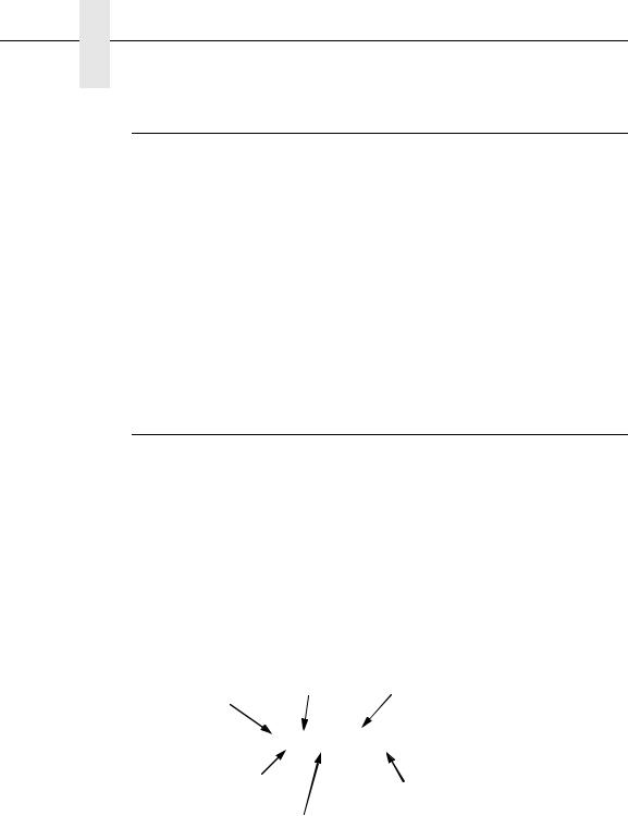
(Off) (On)
Power Switch
Status Indicator
Raise printer cover to use these keys.
SET TOF
UP
PRT CONFIG
PREV NEXT
JOB SELECT
ENTER
DOWN
LCD
PAPER |
|
ON LINE ADVANCE |
VIEW CANCEL |
CLEAR |
EJECT |
Figure 2. Electrical Controls, Cabinet Models
19

Chapter 1 Controls and Indicators
Electrical Controls and Indicators, Pedestal Models (Figure 3)
Switch or |
Function |
Active |
Active |
|
Indicator |
On-line |
Off-line |
||
|
Power Switch |
Turns printer on and off: 1 = on, 0 = off. This switch is also a circuit breaker. |
Status |
On when the printer is on-line, off when the printer is off-line. Flashes to indicate a |
Indicator |
fault or warning. |
LCD |
Liquid Crystal Display. Displays printer status messages, fault messages, and |
|
menus which permit user to set various configurations. |
ON-LINE |
Toggles the printer on-line and off-line. Clears the printer after a fault is corrected |
CLEAR |
and returns the printer to off-line state. |
PAPER |
Prints any data in the buffer then moves paper up one line at the currently active |
ADVANCE |
line spacing. If pressed longer than 1/2 second, moves paper to the next Top Of |
|
Form as defined by the currently active form length. |
VIEW |
Moves the current print position to the tractor area for viewing. When paper is in |
EJECT |
VIEW position, “Printer in View” displays and microstep adjustment feature is |
|
active. (See UP and DOWN keys.) Holding key down for more than 1/2 second |
|
invokes EJECT and paper is advanced two pages. (EJECT can be disabled via |
|
the menus.) Pressing key a second time moves paper back to the print position |
|
from either VIEW or EJECT position. |
CANCEL |
Clears all data from the print buffer (if enabled in the MAINT/MISC menu). |
−Displays next higher level of a configuration menu. In VIEW mode, moves paper
UP |
up 1/72 inch. (See VIEW / EJECT key.) |
↓Displays next lower level of a configuration menu. In VIEW mode, moves paper
DOWN |
down 1/72 inch. (See VIEW / EJECT key.) |
→ |
Displays the next option in a configuration menu. |
NEXT |
|
← |
Displays the previous option in a configuration menu. |
PREV |
|
SET |
Moves paper downward from TOF alignment mark to the print station and sets this |
TOF |
as the first line of print on a page, independent of forms length. If there are data in |
|
the buffers, the printer slews to the page position where printing left off and prints |
|
the data. |
PRT |
Prints the current printer configuration. |
CONFIG |
|
JOB |
Allows fast selection of any stored configuration. Repeated pressing scrolls |
SELECT |
through all saved configurations. Press ENTER to select the displayed |
|
configuration. (ENTER does not have to be unlocked for this function.) |
ENTER |
Enters an option displayed on the LCD into printer non-volatile memory. Starts and |
|
stops printer tests, sets a value, or prints the configuration. This key is locked and |
|
unlocked by a user-selectable key combination. (Refer to the User’s Manual.) |
← + → |
Resets the printer by reloading the power-up configuration and resetting the |
|
internal state. |
20
Printing Conventions in This Manual
(Off) (On)
Power Switch
SET |
PRT |
JOB |
PREV NEXT UP DOWN TOF |
CONFIG |
SELECT ENTER |
LCD
|
|
SET |
PRT |
JOB |
PREV |
NEXT |
TOF |
CONFIG |
SELECT ENTER |
|
UP |
DOWN |
|
|
Status Indicator |
ON-LINE |
PAPER |
VIEW |
|
CLEAR ADVANCE |
EJECT CANCEL |
|
|
ON-LINE |
PAPER |
VIEW CANCEL |
|
CLEAR |
ADVANCE |
EJECT |
Figure 3. Electrical Controls, Pedestal Models
21

Chapter 1 Controls and Indicators
Mechanical Controls and Indicators, All Models (Figure 6)
Control or |
|
|
|
|
|
|
|
|
|
|
|
|
|
|
|
Function |
|||||||||
Indicator |
|
|
|
|
|
|
|
|
|
|
|
|
|
|
|
||||||||||
|
|
|
|
|
|
|
|
|
|
|
|
|
|
|
|
|
|
|
|
|
|
|
|
|
|
|
|
|
|
|
|
|
|
|
|
|
|
|
|
|
|
|
|
|
|
|
|
|
|
|
|
|
|
|
|
|
|
|
|
|
|
|
|
|
|
|
|
|
|
|
|
|
|
|
|
|
|
Forms Thickness |
Sets the platen for paper and forms of different |
||||||||||||||||||||||||
Lever |
thicknesses. Lever must be fully opened (raised) to |
||||||||||||||||||||||||
|
load or unload paper. |
|
|
|
|
|
|
|
|
|
|||||||||||||||
Paper Supports |
Help prevent paper jams by supporting inner sections |
||||||||||||||||||||||||
|
of paper. They are positioned manually by sliding |
||||||||||||||||||||||||
|
them along the shafts. |
|
|
|
|
|
|
|
|
|
|||||||||||||||
Forms Thickness |
Indicates relative thickness of forms and paper. Set |
||||||||||||||||||||||||
Pointer and Scale |
this lever at A for thin (single-part) forms, B for thicker |
||||||||||||||||||||||||
|
forms, and so on. |
|
|
|
|
|
|
|
|
|
|||||||||||||||
Tractors (2) |
Hold and feed paper. Used to set side margin and |
||||||||||||||||||||||||
|
position paper horizontally. |
||||||||||||||||||||||||
Tractor Locks (2) |
Lock tractors in position. |
||||||||||||||||||||||||
Horizontal |
Allows fine positioning of left print margin. Moves |
||||||||||||||||||||||||
Adjustment Knob |
paper and tractors left or right. |
||||||||||||||||||||||||
Vertical Position |
Used to set top of form or first line to be printed. |
||||||||||||||||||||||||
Knob |
Rotate this knob to move paper vertically. Works |
||||||||||||||||||||||||
|
when forms thickness lever is open. |
||||||||||||||||||||||||
Ribbon Loading |
Instructions showing how to load the ribbon correctly. |
||||||||||||||||||||||||
Path Diagrams |
One diagram is cast in relief on the shuttle cover, and |
||||||||||||||||||||||||
|
another is printed on the paper scale. |
||||||||||||||||||||||||
Paper Scale |
A horizontal scale graduated in tenths of an inch, |
||||||||||||||||||||||||
|
useful for setting paper margins counting text |
||||||||||||||||||||||||
|
columns. (See below.) |
|
|
|
|
|
|
|
|
|
|||||||||||||||
|
|
|
|
|
1 inch |
|
|
|
|
|
|
|
|
|
|
||||||||||
|
|
|
|
|
|
|
|
|
|
|
|
|
|
|
|||||||||||
|
|
|
|
|
|
|
|
|
|
|
|
|
|
|
|
|
|
|
|
|
|
|
|
|
|
|
|
|
|
|
|
|
|
|
|
|
|
|
|
|
|
|
|
|
|
|
|
|
|
|
|
|
|
|
|
|
|
|
|
|
|
|
|
|
|
|
|
|
|
|
|
|
|
|
|
|
|
|
|
|
|
|
|
|
|
|
|
|
|
|
|
|
|
|
|
|
|
|
|
|
|
|
|
|
1 |
|
|
|
|
10 |
|
|
20 |
||||||||||||||||
|
|
|
|
|
|||||||||||||||||||||
|
|
|
|
|
|
|
|
|
Column |
||||||||||||||||
|
|
|
|
0.1 inch |
|||||||||||||||||||||
|
|
|
|
|
|
|
|
|
|
|
|
|
|
|
|
|
Number |
||||||||
|
|
|
|
|
|
|
|
|
|
|
|
|
|
|
|
|
|
|
|
|
|
|
|
|
|
22

Printing Conventions in This Manual
Paper
Supports
|
Left Tractor |
|
Horizontal |
Right Tractor |
|
Adjustment |
||
|
||
Knob |
|
|
|
Tractor Lock |
|
Tractor Lock |
Vertical |
|
|
Position |
|
|
Knob |
Ribbon Loading
Path Diagrams Forms Thickness
Lever and Scale
Forms
Thickness
Pointer
Figure 4. Mechanical Controls and Indicators, All Models
23

Chapter 1 Tools, Test Equipment, and Supplies
Tools, Test Equipment, and Supplies
For field level maintenance of the printer, you will need these tools: Adapter, 1/4 in. hex to 1/4 in. square, Uticaâ HW-18
Alcohol, anhydrous
Allen Wrench, 1/16 inch
Allen Wrench, 3/32 inch
Allen Wrench, 7/64 inch
Allen Wrench, 5/64 inch
ESD Wrist Strap
Feeler Gauge, .010 inch
Feeler Gauge, .011 inch
Feeler Gauge, .040 inch
Force Gauge, (Chatillonä NY, Gauge-r, 0-20 lb., CAT 719-20)
Hex bit, 3/16 in., torque screwdriver
Hex bit, 3/32 in., torque screwdriver
Hex bit, 5/32 in., torque screwdriver
Hex bit, 5/64 in., torque screwdriver
Lubricant, Bearing (Printronix P/N 101805-001)
Nut Driver, 1/4 inch
Nut Driver, 5/16 inch
Nut Driver or Open End Wrench, 7/32 inch
Open End Wrench, 5/16 inch
Pliers, Grip Ring, External
Screwdriver, flat tip
Screwdriver, Phillips, #1
Screwdriver, Phillips, #2
Screwdriver, Torque, Utica TS-35
Tie Wraps, 4 inch
Torxâ T-10 Driver
24

2 Preventive Maintenance
Cleaning the Printer
The printer is designed to require very little maintenance. Aside from normal replenishment of paper and ribbons, the only preventive maintenance required is periodic cleaning.
Because operating conditions vary widely, the user must determine how often to clean the printer.
Since there is no guarantee that the user will clean the printer regularly, you should clean the printer whenever you are called to service it. The cleaning procedures in this chapter pertain to all models.
WARNING Always disconnect the AC power cord before cleaning the printer.
CAUTION Do not use abrasive cleaners, particularly on the window.
Do not drip water into the printer. Damage to the equipment will result. Do not spray directly onto the printer when using spray solutions. Spray the cloth, then apply the dampened cloth to the printer.
Do not vacuum the circuit boards.
Cleaning the Outside Surfaces
1.Power off the printer.
2.Disconnect the AC power cord from the printer or the power source.
3.Remove paper and the ribbon.
4.Dampen a clean, lint-free cloth with water and a mild detergent or with window cleaning solution. The cloth must be damp, not wet. Wipe down the outside surfaces of the printer.
5.Dry the outside surfaces with a clean, lint-free cloth.
6.Open the printer cover.
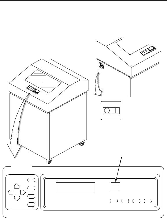
7.Using a soft-bristled, non-metallic brush (such as a toothbrush), brush paper dust and ribbon lint off the tractors, shuttle cover assembly, base casting, and ribbon guides. Vacuum up the residue. (See Figure 5.)
8.Wipe the splined shaft with a soft cloth.
CAUTION To avoid corrosion damage, use only alcohol when cleaning printer mechanical elements, and make sure the cleaning solution contains no water.
25
Chapter 2 Cleaning the Outside Surfaces
9.Using a cloth dampened (not wet) with alcohol, clean the ribbon guides.
10.Vacuum up dust and residue from the lower cabinet.
11.Wipe the interior of the lower cabinet with a clean, lint-free cloth dampened with water and a mild detergent or window cleaning solution.
12.Dry the cabinet interior with a clean, lint-free cloth.
13.Clean the shuttle frame assembly, as described in the next section.
3
2 
1 
NOTE: Cabinet model shown. Procedure is the same for pedestal model.
Legend:
1)Base Casting
2)Shuttle Cover Assembly
3)Splined Shaft
4)Tractors
5)Forms Thickness Lever
6)Ribbon Guide
4
 5
5
6
Figure 5. Cleaning Inside the Cabinet or Top Cover
26
Cleaning the Shuttle Frame Assembly
1.Remove the shuttle cover assembly (page 160).
2.Remove the shuttle frame assembly (page 198).
3.Remove the paper ironer (page 176).
WARNING Over time, the upper edge of the paper ironer can become sharp. To avoid cutting yourself, handle the paper ironer on the sides.
4.Moisten a clean, soft cloth with alcohol. Wipe the paper ironer to remove lint, ink, and paper residue.
5.Install the paper ironer (page 176).
6.Remove the hammer bank / ribbon mask cover assembly (page 157).
CAUTION The ribbon mask is thin and easily bent. Be careful not to crease or kink the ribbon mask when handling and cleaning it.
7.Moisten a clean, soft cloth with alcohol. Wipe the hammer bank cover and ribbon mask to remove lint, ink, and paper residue. Clean the holes in the cover strips. Carefully wipe between the hammer bank cover and the ribbon mask (early models).
CAUTION Do not use any solvents or liquids to clean the hammer tips. Clean the hammer tips gently—too much pressure can chip them.
8.Using a stiff, non-metallic brush (such as a toothbrush), gently brush the hammer tips to remove lint and ink accumulations. (See Figure 6.) Vacuum up any residue.
NOTE: P5005 hammer bank is shown. Procedure is the same
for all hammer banks.
1 
Legend:
1)Hammer Tip
Figure 6. Cleaning the Hammer Tips
CAUTION The hammer bank contains a strong magnet. To prevent damage to the hammer tips, do not let the hammer bank cover assembly snap into place as the hammer bank magnet attracts it. Any impact of the cover against the hammer bank can break hammer tips.
9.Install the hammer bank / ribbon mask cover assembly (page 157).
10.Install the shuttle frame assembly (page 198).
27
Chapter 2 Cleaning the Card Cage Fan Assembly
11.Install the shuttle cover assembly (page 160).
12.Clean the card cage fan assembly, as described in the next section.
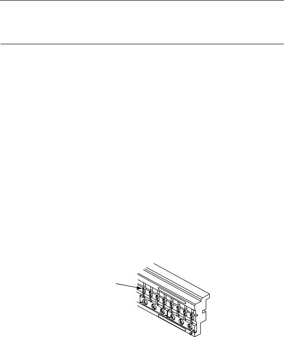
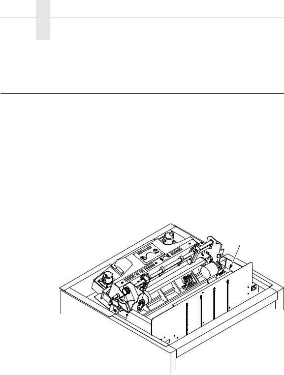
Cleaning the Card Cage Fan Assembly
1.Cabinet Models: Remove the paper path (page 177). Pedestal Models: Remove the top cover assembly (page 161).
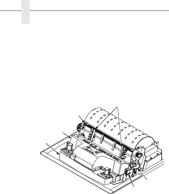
2.Vacuum the card cage fan assembly and surrounding areas to remove paper particles, dust, and lint. (See Figure 7.)
3.Cabinet Models: Install the paper path (page 177)
Pedestal Models: Install the top cover assembly (page 161).
4.Return the printer to normal operation (page 107).
NOTE: Cabinet model shown. Procedure is the same for pedestal model.
1
Legend:
1)Card Cage Fan Assemb.y
Figure 7. Cleaning the Card Cage Fan Assembly
28

3 Troubleshooting
Introduction
This chapter lists fault messages and symptoms, and provides procedures for troubleshooting printer malfunctions.
Always have the User’s Manual handy when you troubleshoot because this manual does not cover printer operation or configuration. You must operate the printer to check its performance, and sometimes you may have to reconfigure it.
Troubleshooting Aids
Troubleshooting is faster and more effective if you understand the equipment and make use of all available tools.
This manual provides a number of troubleshooting aids to help you isolate printer malfunctions:
• “Start Here” Logic Tree |
page 30 |
|
• |
Troubleshooting Display Messages |
page 31 |
• |
Message List |
page 31 |
• |
Troubleshooting Other Symptoms |
page 36 |
• |
General Symptom List |
page 36 |
• |
Troubleshooting Procedures |
page 38 |
• |
Diagnostic Printer Tests |
page 92 |
• |
Hex Code Printout |
page 95 |
• |
ASCII Character Set |
page 97 |
• The Power On Sequence |
page 99 |
|
• Appendix A: Wire Data |
page 259 |
|
29
Chapter 3 Start Here...
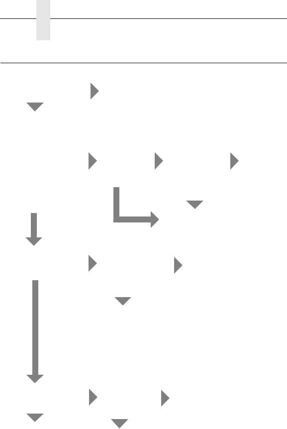
Start Here...
Are you here because of an |
|
error message? |
YES |
NO |
|
Power on the printer and observe the control panel for the following sequence of events (retry as required):
1. All black squares appear on the display.
2. Display goes blank. YES
3. TESTING HARDWARE PLEASE WAIT appears on display.
Power on the printer. Did steps 1, 2, and 3 occur?
NO
Go to Troubleshooting Display Messages, page 31.
After about 10 seconds did YES
the fans come on?
NO
Did the status |
|
indicator lamp |
|
come on and |
Printer initialized |
ONLINE appear |
successfully. |
on the display? (If YES |
Other symptoms |
default is |
are listed in |
OFFLINE, status |
Table 3: page |
indicator will not |
36. |
come on.) |
|
NO |
|
Go to Printer |
|
does not |
|
initialize, page 71. |
|
Did the fans come on after 10 seconds?
NO
Did ANY of steps 1 thru 3 occur?
NO
Go to No power, and control panel is blank, and card cage fan is not running, page 62.
YES
YES
Press ON LINE. Press PRT CONFIG.
Press ENTER. YES Does machine configuration
print?
NO
The Control Panel is not functioning (Table 3: page 36) —OR—
Printer does not initialize, page 71.
Are there black squares on the YES control panel?
NO
Go to Printer does not initialize, page 71.
Go to the Control Panel section of Table 3: page 36
Go to Black squares on control panel display, page 44.
30
Loading...