

Page 1
OPERATING
Fax: (630) 462-1460
Toll Free: 1-800-PCASTLE
545-502revB Printed in USA 1/06 © 2006
This product is warranted to be free from defects in material
and/or workmanship for a period of 1 year from date of original
installation, not to exceed 18 months from the date of
manufacture.
Any component which proves to be faulty in material and/or
workmanship will be replaced or repaired (at the option of
Prince Castle, Inc.) without cost to the customer for parts and
labor. This warranty covers on-location service (i.e. trip
charges and/or mileage). Travel mileage is limited to 100 miles
(200 Kilometers) round trip (one trip warranty) from an
authorized service agency or its sub-service agency.
This warranty is subject to the following exceptions/conditions:
• Use of any non-genuine Prince Castle parts voids this
warranty.
• All labor to be performed during regular work hours.
Overtime premium (the incremental amount) will be charged
to the customer.
• Damage caused by carelessness, neglect and/or abuse
(e.g., dropping, tampering or altering parts, equipment
damaged in shipment, by fire, flood or an act of God) is not
covered under this warranty.
• All problems due to operation at voltages other than that
specified on equipment nameplates are not covered by this
warranty. Conversion to correct voltage is the customer’s
responsibility.
• This equipment must be serviced by Prince Castle
Authorized Service Agency or a Prince Castle Service
Technician during the warranty period.
LIMITED WARRANTY
INSTRUCTIONS
Dedicated Holding Bin
Model No. DHB2PT-30
DHB4PT-30 & DHB4-30
DHB2PT-30 DHB4PT-30
DHB4-30 (Non Pass Through)
ELECTRICAL SPECIFICATION
Model Volts HZ Watts Amps
DHB2-30 208 60 1800 8.6
DHB2-30L 120 60 1650 13.8
DHB2-30J 200 50/ 60 1650 8.3
DHB2PT-30 208 60 1800 8.7
DHB2PT-30L 120 60 1650 13.8
DHB2PT-30J 200 50/60 1650 8.3
DHB2PT-30CE 220-240 50 1900 7.9
DHB2PT-30GB 240 50 1900 7.9
TABLE OF CONTENTS PAGE
Installation..................................................................... 2
Programming.............................................................. 2-3
Operating ....................................................................... 4
Cleaning ........................................................................ 4
Parts List....................................................................... 4
Exploded View .............................................................. 5
Troubleshooting ............................................................ 6
Wiring Diagrams ........................................................... 7
DHB4PT-30 208 60 3600 17.3
DHB4PT-30J 200 50/60 3400 17.0
DHB4PT-30CE 220-240 50 3800 16.0
DHB4PT-30GB 240 50 3800 16.0
DHB4-30 208 60 3600 17.3
DHB4-30J 200 50/60 3400 17.0
DHB4-30CE 220-240 50 3800 16.0
DHB4-30GB 240 50 3800 16.0
355 East Kehoe Blvd. Carol Stream, IL 60188
Tel: (630) 462-8800
Page 2
INSTALLATION
2 545-502revBPrinted in USA 1/06 © 2006
1. After you have removed the unit from the carton,
inspect the unit for signs of damage. If there is
damage to the unit:
z Notify carrier within 24 hours after delivery.
z Save carton and packing materials for inspection
purposes.
z Contact the Prince Castle Customer Sales
Department at 1-630-462-8800 to arrange for
a replacement to be sent.
1. Place the bin on a counter and seal its base to
the counter with food-approved sealant.
2. Insert the power cord into a proper voltage
receptacle. Note: This should be a dedicated
outlet. No other equipment should be operating
on this line (i.e. fryers, refrigerators, etc.)
3. Install the rack and pan covers into the bin. Pan
covers are used for pans that hold grilled,
broiled, or baked meat products. Do not install
the pan cover on pans that hold fried foods.
4. Turn the power switch on. Allow 30 minutes for
warm-up.
The SET POINT LED indicator will be on
when the Set-point mode is selected. Press
and hold the Prince Castle button then press
and hold the SET-POINT button to program
the temperature for the selected heater.
• ACTUAL TEMP: The actual temperature is
displayed for the selected heaters when this
button is pressed during the operating mode
and the ACTUAL LED indicator will be on.
• UP ARROW and DOWN ARROW: When
pressed in the operating mode, will scroll
through the upper and lower heaters for all
four cavities to display either the actual or
set point temperature. The LED next to the
UPPER SHELF or LOWER SHELF will be on
to indicate which heater is being selected.
The letters A, b, C, and d ( A & B for 2
Shelf Units) are displayed to show the
selected cavity location for the upper and
lower heaters.
When reading the digital display from left-to-right,
the following information is displayed: The Upper or
Lower heater for the selected cavity (A, b,C,or
d)(A & B for 2 shelf units, if power is being applied
to the heater, and if the display temperature is the
ACTUAL or SET-POINT temperature.
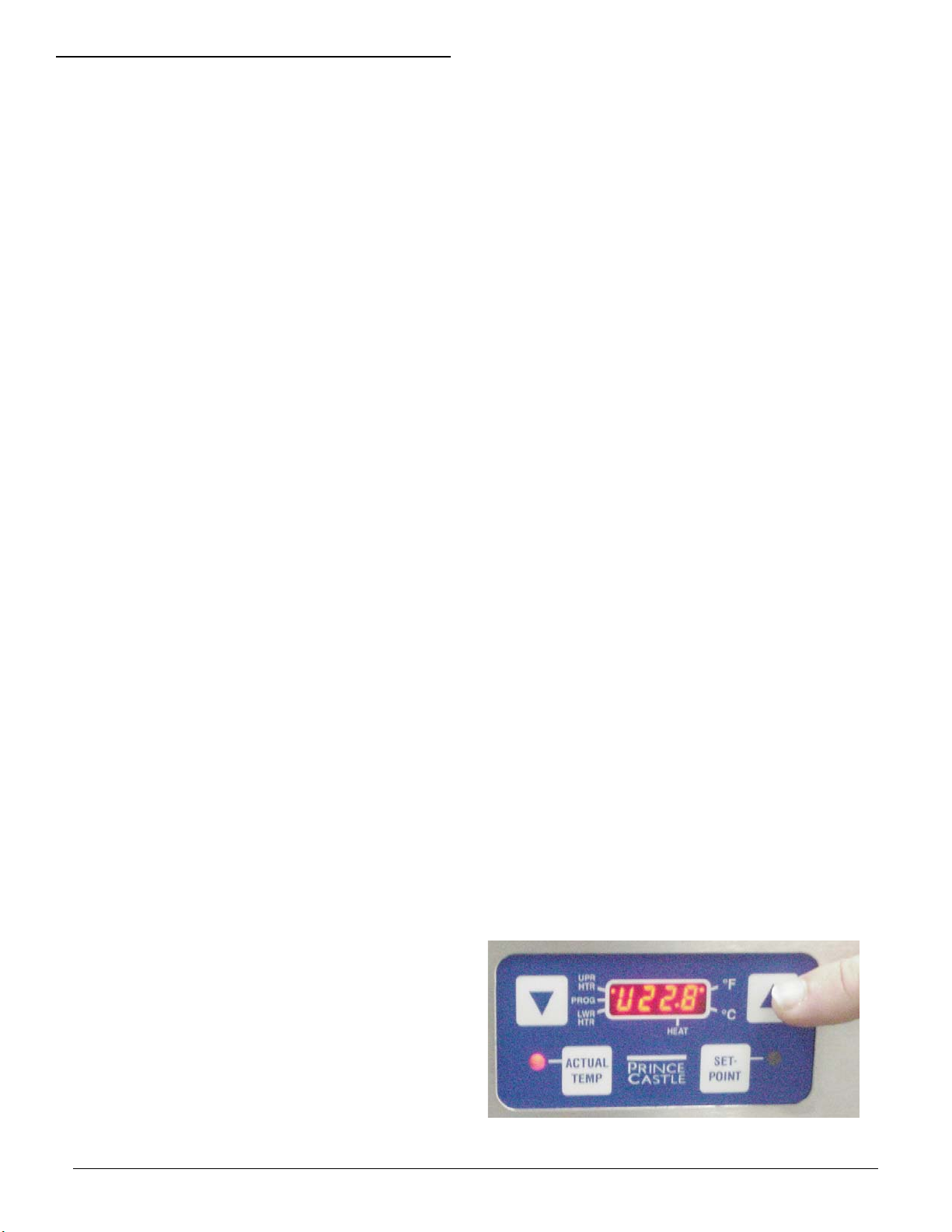
THE TEMPERATURE CONTROL
PANEL
1. Indicators and Displays
Within the four character digital display there are
LED indicators. The four character digital display shows the numerical value of the temperature, and the LED indicators display the following:
• The LED indicator next to the UPR HTR (for
the UPPER HEATER) is on when the tem-
perature being displayed is for the upper
heater.
• The LED indicator next to the PROG is on
when in the Program Mode.
• The LED indicator next to the LWR HTR for
the LOWER HEATER) is on when the tem-
perature being displayed is for the lower
heater.
• The LED indicator next to the HEAT is on
when power is applied to the selected heater.
2. Control Panel buttons and LED indicators
• SET POINT: The set-point temperature is
displayed for the selected heaters when this
button is pressed during the operating mode.
PROGRAMMING
The temperature adjustment range for a heater is:
OFF, 150°F to 225°F (OFF, 65°C to 107°C ). The
recommended starting setpoint temperatures are:
• 190°F (88°C) for the Upper Shelves.
• 190°F (88°C) for the Lower Shelves.
• NOTE: Through testing, these temperatures
may be increased or decreased as long as
the food quality and desired temperature of
the product being tested is maintained.
Programming Set Point Temperatures
1. Press and release the UP or DOWN arrow button
until the heater in the cavity to be changed is
selected.
Page 3
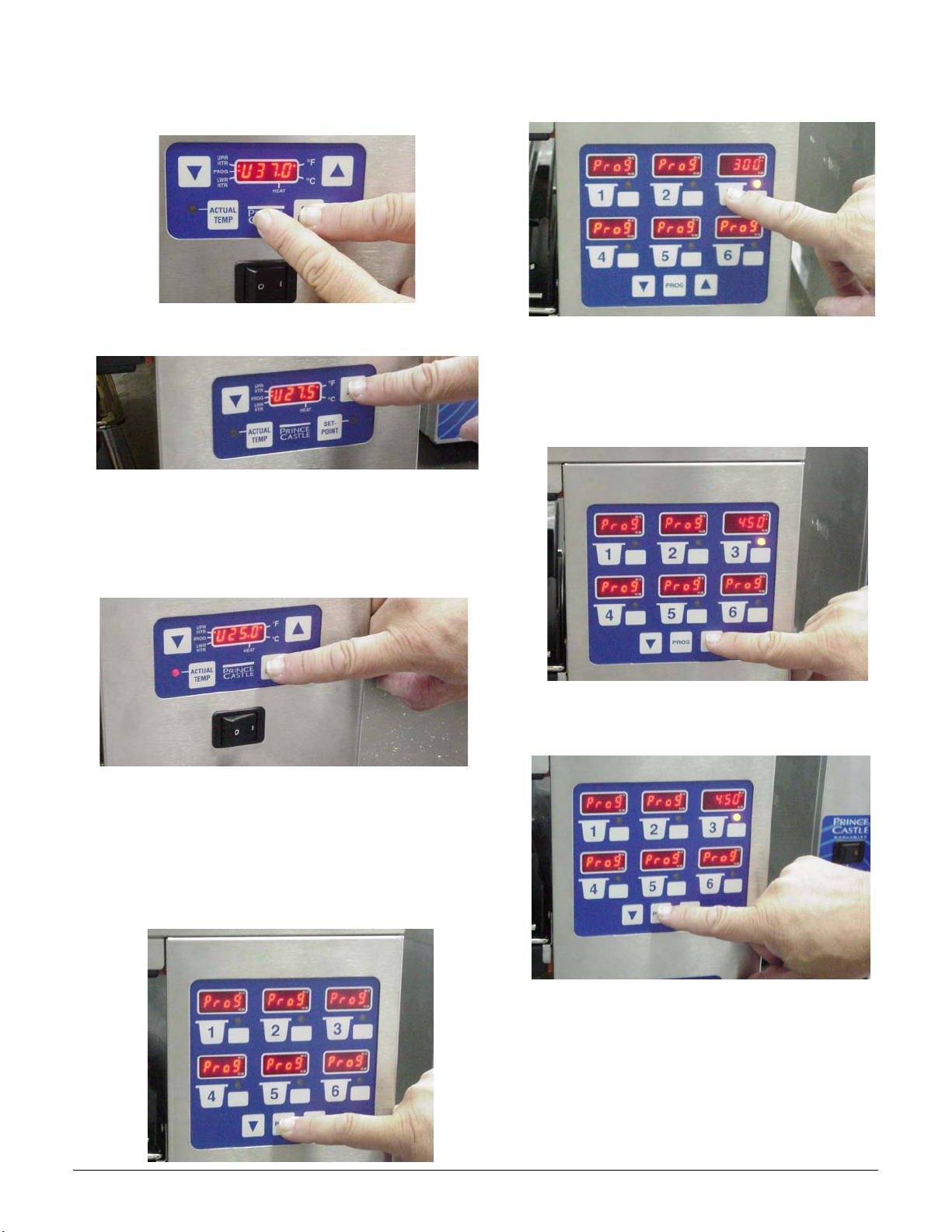
2. Press and hold the SET POINT button then
545-502revB 3 Printed in USA 1/06 © 2006
press and hold the PRINCE CASTLE button for 6
seconds. The LED indicator next to PROG will
light to indicate the Program Mode is active.
3. Use the UP and DOWN arrow buttons to increase or decrease the setpoint temperature.
4. Press the SET POINT button to end the Program
Mode and store the setpoint temperature value
(the LED next to PROG will turn off). The controller will regulate to the new setpoint temperature.
2. Press the timer button to change. The timer
button LED will change to yellow and the current
programmed time is displayed.
3. Press the UP or DOWN arrow buttons to set the
time. Time values below 60 minutes will cause
the M:S led to light, and time values equal to or
greater than one hour will cause the H:M led to
light.
5. Repeat Steps 1-4 for remaining heaters.
Programming Timers
1. Press and hold the PROG button for 6 seconds.
All six timer displays will change to show Prog.
4. Repeat steps 2 and 3 for other timers. Press the
PROG button to store the new values and end
the Program Mode.
Page 4

OPERATION
4 545-502revBPrinted in USA 1/06 © 2006
The default temperature mode is set to display in
Celsius. To change to Fahrenheit, turn the power
switch off. Press and hold the UP arrow then turn
the power switch to the on position. After two
seconds, release the UP arrow button. To change
back to Celsius, turn the power switch to the off
position, press and hold the DOWN arrow and turn
the power switch to the on position. After two
seconds, release the DOWN arrow button.
To view the actual heater temperature, press the
ACTUAL TEMP button. The LED indicator next to
the ACTIVE TEMP button will light. To view the
temperature if a heater, press the UP or DOWN
arrow button to select the heater.
1. Press the timer button to start the timer. The
timer display shows the time value and counts
down to zero. The timer button LED is green for
the first 70 percent of the hold time, yellow for
the next 20 percent, and red for the final 10
percent.
2. At the end of the hold time, an alarm sounds, the
timer button LED flashes, and the display flashes
End.
CLEANING
Caution: This bin is not watertight. Do
not clean with Water Jet/Jet Spray. Do not
immerse the bin with water.
Caution: Before unplugging the power
cord, make sure the power switch is in the
OFF position.
1. Unplug the power cord from the outlet.
2. Allow the bin to cool down (approximately 25
minutes).
3. Remove the racks, pans and pan covers. Clean
in power washer.
4. Wipe down surface with a damp cloth. Do not
use a green Scotch Bright pad, unapproved
cleaner, ice or water.
5. Reinstall racks, pans, and pan covers.
PARTS LIST
3. Press the timer button to cancel the alarm.
4. To cancel an active timer, quickly press the timer
button three times.
5. To adjust the alarm sound volume, press and hold
the PROG button then press the UP button.
Release both button, the alarm is set to the high
level. Press and hold the PROG button then
press the DOWN button. Release both buttons;
the alarm is set to the low level.
ITEM PART DESCRIPTION
1 72-356S Power Cord (DHB4PT-30 &
DHB4-30)
72-342S Power Cord (DHB2PT-30)
2 548-050 Cover, Side (DHB2PT-30)
545-031 Cover, Side (DHB4PT-30 &
DHB4-30)
3 545-054 Cover, Top
4 545-044S PCB, Timer
5 545-046S PCB, Display
6 545-047S Main PCB (DHB4PT-30 &
(Not Shown) DHB4-30)
548-051S Main PCB (DHB2PT-30)
(Not Shown)
7 545-034S Overlay & Face Plate (Timer)
8 545-039S Overlay & Face Plate (Main)
9 545-050 Cover, Bottom
10 545-076 Insulation
11 78-184S Lighted Rocker Switch
12 548-017S Upper Heater Assy.
13 548-013S Lower Heater Assy.
14 545-072 Cover, Rear (DHB4-30 Only)
(Not Shown)
Page 5

3
545-502revB 5 Printed in USA 1/06 © 2006
4
7
5
2
1
12
13
1
8
11
10
2
9
Page 6

TROUBLESHOOTING
6 545-502revBPrinted in USA 1/06 © 2006
Problem Cause Solution
A. Display flashes Open relay. Replace Power Circuit Board
“Opn” & “rEL” Circuit inoperable
B. Display flashes Shorted relay. Replace Power Circuit Board.
“SHr” & “rEL” Circuit inoperable.
Open heater. Test heater resistance.(150.2
Ohms) Replace Heater
Power and Main Circuit Boards. Verify ribbon cable connection.
C. Display shows “LLL” Temperature is below 75° F Normal display during warm up.
Heater inoperable. Test heater resistance.(150.2 Ohms)
Probe inoperable. Check for open thermocouple wires from
Relay Inoperable probe. Replace heater/probe assembly.
D.Display shows “HHH” for Temperature is above300° F Diagnostic circuit inoperable. Replace
an extended period of time (abnormal operation) Power Circuit Board.See B above.
and heater surface
temperature is hot.
Display shows “HHH” for Probe is inoperable Check for pinched thermocouple
an extended period of time wires from probe. Replace heater/probe
and heater surface assembly.
temperature is cool.
To reset all times and temperatures to the factory settings, turn unit off, press and
hold the UP and DOWN ARROW BUTTONS at the same time, turn unit back on. A “P”
will appear in the display and all times and temperatures will be reset to the original
factory settings.
Page 7

WIRING DIAGRAM (DHB4PT-30 & DHB4-30)
545-502revB 7 Printed in USA 1/06 © 2006
UPPER "A"
HEATER
LOWER "A"
HEATER
UPPER "b"
HEATER
LOWER "b"
HEATER
UPPER "C"
HEATER
LOWER "C"
HEATER
UPPER "d"
HEATER
LOWER "d"
HEATER
THERMOCOUPLE
THERMOCOUPLE
THERMOCOUPLE
THERMOCOUPLE
THERMOCOUPLE
THERMOCOUPLE
THERMOCOUPLE
THERMOCOUPLE
BLK
WHT
WHT
RED
BLK
WHT
WHT
RED
BLK
WHT
WHT
RED
BLK
WHT
WHT
RED
TC
YEL
UPPER
J5
LOWER
UPPER
J6
LOWER
UPPER
J7
LOWER
UPPER
J8
LOWER
J19
CONTROLLER
RIBBON
LOWER
UPPER
UPPER
LOWER
J14
LOWER
UPPER
UPPER
LOWER
P2 P1
BLU
J1
J2
J3
J4
P3
BRN
BRN
BLU
TIMERS 1-6
J7
YEL
SPEAKER
CONTROLLER
DISPLAY
RIBBON
POWER
SWITCH
TIMERS 7-12
J7
YEL
J2
YEL
ORG OR YEL
SPEAKER
J2
YEL
ORG OR YEL
BRN
BLU
ORG OR YEL
BLU
BRN
POWER
GRN/YEL
CORD
WIRING DIAGRAM (DHB2PT-30 & DHB2-30)
UPPER "A"
HEATER
LOWER "A"
HEATER
UPPER "b"
HEATER
LOWER "b"
HEATER
THERMOCOUPLE
THERMOCOUPLE
THERMOCOUPLE
THERMOCOUPLE
TC
J5
J6
J7
J8
J19
YEL
1
2
3
4
CONTROLLER
J14
J3
1
J4
2
J13
3
J15
4
P3
P2
P1
GRN/YEL
BRN
BLU
BRN
BRN
BLU
BLU
SPEAKER
CONTROLLER
DISPLAY
RIBBON
POWER
SWITCH
TIMERS 1-6
J7
YEL
SPEAKER
J2
YEL
ORG OR YEL
ORG OR YEL
BLU OR WHT
BRN OR BLK
POWER
CORD
GRN/YEL
 Loading...