

InstructionSheet
InstructionSheet
IMPORTANT SAFETY INFORMATION. READ AND FOLLOW ALL SAFETY INSTRUCTIONS. Follow label information
and instructions concerning Wet or Damp Locations, installation near combustible materials, insulation, building materials,
and proper lamping. Do not install in areas subject to combustible vapors or gases. Before wiring to power supply and
during servicing or relamping, turn off power at fuse or circuit breaker. All servicing or relamping must be performed by
qualified service personnel. Product must be grounded to avoid potential electric shock or other potential hazard.
Product must be mounted in locations and at heights and in a manner consistent with its intended use, and in
compliance with the National Electrical Code and local codes. The use of accessory equipment not recommended by
the manufacturer or installed contrary to instructions may cause an unsafe condition. Do not block light emanating from
product in whole or part, as this may cause an unsafe condition. Do not allow items such as drapes, curtains, screens or
the like to come into contact with the product or to block light from the product, as this may cause an unsafe condition.
INSTALLATION INSTRUCTIONS
SIGNOS 6 ARCHITECTURAL ELEMENTS
BRACKET INSTALLATION - CFR6, CFQ6, CFT6, CFT6H, CFR61
1. Remove lamp(s) and reflector from luminaire and verity that luminaire is secured to ceiling
supports and is stable. Lower edge of luminaire aperture (A) should be approximately .125
inch above room side ceiling surface; adjust luminaire ceiling position if necessary.
2. Remove “L” brackets (B) from package. Verify that triangular brackets (D) are at top of “L”
bracket slots. Attach brackets to luminaire by hooking triangular bracket tab (E) onto slot (F) of
luminaire aperture. Rotate top of bracket over top edge of aperture until bracket’s upper tabs (G)
snap into holes (H) located on top surface of luminaire flange.
3. Loosen screws (I) on brackets, adjust brackets so they are in contact with ceiling, and retighten
screws.
4. Replace reflector and lamp(s).
Part No. . . . . . . . . . . . . . . . . . . . . . . . . . . . . . . .138550100
www.prescolite.com • Prescolite TollFree Technical Support 1.888.PRS.4TEC • Hours: 8am - 5pm ET
D
G
I
E
B
A
F
H
CEILING
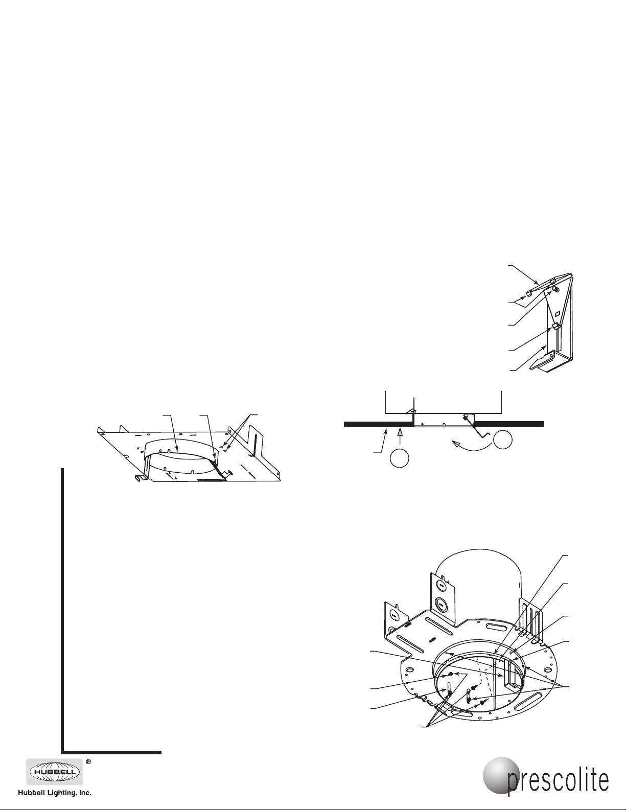
BRACKET INSTALLATION - 79X, 79M
1. Remove lamp and reflector from luminaire and verity that
luminaire is secured to ceiling supports and is stable. Loosen 3
screws (J) holding luminaire housing (K) in place.
2. Remove “L” brackets (B) from package. Remove triangle
brackets (D) from “L” brackets.
3. Attach “L” brackets to luminaire by inserting brackets between
luminaire housing (K) and flange (L) at 2 positions marked with
notches (M) on aperture. “L” bracket slots must be aligned with
housing slots (N) at 180° and brackets must be pushed up
until bracket slots clear upper holes (O). Insert 2 sheet metal
screws (P) into upper holes (O) and 2 through housing slots
(N) and bracket slots and into holes (Q) on flange; do not
tighten screws.
4. Lower edge of housing (K) should be approximately .125 inch
above room side ceiling surface; adjust luminaire housing
position if necessary. Adjust brackets so they are in contact
with ceiling and tighten 4 screws (P) for the “L” brackets and 3
screws (J) for luminaire housing.
5. Replace reflector and lamp.
2
PUSH UNTIL BRACKET
(B) CONTACTS CEILING
B
O
N
P
1
ROTATE
UNTIL
TABS (G)
SNAP INTO
HOLES (H)
L
K
Q
M
J
101 Corporate Drive • Spartanburg, SC 29303
With representatives offices in principal cities throughout North America.
Copyright 2005, 08/05 revision, All Rights Reserved - Printed in U.S.A.

InstructionSheet
Part No. . . . . . . . . . . . . . . . . . . . . . . . . . . . . . . .138550100
www.prescolite.com • Prescolite TollFree Technical Support 1.888.PRS.4TEC • Hours: 8am - 5pm ET
BRACKET INSTALLATION - RHD6
1. Remove lamp and reflector from luminaire and verity that luminaire is secured to
ceiling supports and is stable. Lower edge of luminaire aperture (S) should be
approximately .125 inch above room side ceiling surface; adjust luminaire position if
necessary.
2. Remove “L” brackets (B) from package. Remove triangular brackets (D) from “L”
brackets; save machine screws (I) for reuse.
3. Attach brackets to luminaire by placing brackets into flange slots (U) and inserting
machine screws (I) through bracket slots and into flange holes (V). Adjust brackets
so they are in contact with ceiling and tighten machine screws (I).
4. Replace reflector and lamp.
TRIM INSTALLATION
Note: frosted glass and plastic parts are easily
stained with body oils or other contaminants; use
gloves or extreme care to maintain clean
appearance.
1. Attach Signos trim safety retainer (AA) to “L” bracket (B) by
threading wire end into hole (BB), first inserting into the side
away from the aperture.
2. Orient Signos trim so attachment springs (CC) are aligned
with “L” brackets (B) and trim is centered below aperture.
Rotate trim counterclockwise until safety retainer (AA)
reaches the end of its slot to position springs (CC) for mounting,
keeping trim centered. Push trim to ceiling, insuring that “L”
brackets (B) insert inside mounting flange (DD). With Signos
trim pushed against ceiling, rotate clockwise until trim locks
into place.
3. With light force, pull Signos trim to verify proper installation;
correctly installed trim will hold securely.
SPECIAL NOTES
Do NOT install decorative trim if parts
are damaged or cracked. Do NOT
disassemble decorative trim.
DD
AA
V
U
B
S
I
CC
BB
B
101 Corporate Drive • Spartanburg, SC 29303
With representatives offices in principal cities throughout North America.
Copyright 2005, 08/05 revision, All Rights Reserved - Printed in U.S.A.
PUSH TRIM
TO CEILING
3
2
1
ROTATE TO
POSITION SPRINGS
ROTATE TO
LOCK
 Loading...