


Operator’s Manual
DuraChill Airand Water-Cooled 1.5 HP Chillers
110-392
11-03-11
110-392 |
1 |
Table of Contents
Introduction.............................................................................................................................................................. |
3 |
Standard and Optional Features............................................................................................................................ |
3 |
Standard Features.............................................................................................................................................. |
3 |
Optional Features............................................................................................................................................... |
3 |
General Safety Information .................................................................................................................................... |
4 |
Safety Recommendations...................................................................................................................................... |
4 |
Regulatory Compliance and Testing...................................................................................................................... |
6 |
Unpacking .............................................................................................................................................................. |
6 |
Contents................................................................................................................................................................. |
6 |
Controls and Components ..................................................................................................................................... |
7 |
Control Panel...................................................................................................................................................... |
7 |
Front ................................................................................................................................................................... |
7 |
Rear -- 230V, 240V, and 208-230V Units .......................................................................................................... |
8 |
Rear -- 380V and 460V Units ............................................................................................................................. |
8 |
Quick Start................................................................................................................................................................ |
9 |
Installation and Startup......................................................................................................................................... |
10 |
Site Requirements................................................................................................................................................ |
10 |
Ambient Temperature and Relative Humidity .................................................................................................. |
10 |
Location ............................................................................................................................................................ |
10 |
Clearance ......................................................................................................................................................... |
10 |
External Piping ..................................................................................................................................................... |
11 |
General Considerations.................................................................................................................................... |
11 |
Process Fluid Connections............................................................................................................................... |
12 |
Facility Water Connections............................................................................................................................... |
12 |
Reservoir Drain................................................................................................................................................. |
12 |
Reservoir Vent.................................................................................................................................................. |
12 |
Process Coolant................................................................................................................................................... |
13 |
Electrical Power ................................................................................................................................................... |
14 |
Phase Requirements (if applicable) ................................................................................................................. |
14 |
Optional Signal Inputs/Outputs ............................................................................................................................ |
14 |
Ambient / External Temperature Probe............................................................................................................ |
14 |
RS-232/RS-485 Serial Output .......................................................................................................................... |
14 |
Remote On / Off Port........................................................................................................................................ |
14 |
4-20mA Set Point Control................................................................................................................................. |
14 |
Startup.................................................................................................................................................................. |
15 |
Facility Water Flow (water-cooled units only)................................................................................................... |
15 |
Filling the Reservoir.......................................................................................................................................... |
15 |
Starting Process Fluid Flow.............................................................................................................................. |
15 |
Normal Operation .................................................................................................................................................. |
16 |
Selecting the Temperature Unit ........................................................................................................................... |
16 |
Displaying and Adjusting the Set Point................................................................................................................ |
16 |
Selecting the Internal / External Temperature Display ........................................................................................ |
16 |
Displaying and Adjusting the Ambient Tracking Offset........................................................................................ |
17 |
Displaying and Adjusting the Remote Control Temperature ............................................................................... |
17 |
Selecting the Pressure / Flow Rate Display and Units ........................................................................................ |
17 |
Setting Operational Parameters / Limits .............................................................................................................. |
18 |
High Temperature Limit (HL)............................................................................................................................ |
20 |
Low Temperature Limit (LL) ............................................................................................................................. |
21 |
High Ambient Temperature Limit (HA) ............................................................................................................. |
21 |
Maximum Fluid Pressure (FP).......................................................................................................................... |
21 |
Minimum Flow Rate (FL) .................................................................................................................................. |
22 |
Auto-Refrigeration Temperature (AF)............................................................................................................... |
22 |
Maximum External / Internal Temperature Differential (Sd)............................................................................. |
22 |
Remote Probe (rP) ........................................................................................................................................... |
23 |
110-392 |
1 |
Internal Calibration Offset (c1) ......................................................................................................................... |
23 |
External Calibration Offset (c2) ........................................................................................................................ |
24 |
Flow Rate Calibration (Fc)................................................................................................................................ |
24 |
Current Control (CC) (Optional) ....................................................................................................................... |
25 |
Baud Rate (PC) ................................................................................................................................................ |
25 |
Fuse Bits (Fb) ................................................................................................................................................... |
25 |
Display, Alarm and Error Messages .................................................................................................................... |
26 |
Adjusting the High Pressure Bypass Setting ..................................................................................................... |
28 |
Enabling / Disabling the Local Lockout .............................................................................................................. |
28 |
Over-Temperature Protection............................................................................................................................... |
28 |
Routine Maintenance and Troubleshooting ....................................................................................................... |
29 |
Routine Maintenance ........................................................................................................................................... |
29 |
Condenser, Air Vents and Reusable Filter....................................................................................................... |
29 |
Fluid Filter......................................................................................................................................................... |
29 |
Fluid Level ........................................................................................................................................................ |
29 |
Cleaning ........................................................................................................................................................... |
29 |
Temperature Calibration................................................................................................................................... |
29 |
Troubleshooting ................................................................................................................................................... |
30 |
Diagnostic Mode .................................................................................................................................................. |
31 |
Technical Information ........................................................................................................................................... |
32 |
Controller Specifications ...................................................................................................................................... |
32 |
General Specifications ......................................................................................................................................... |
32 |
Pump Performance .............................................................................................................................................. |
33 |
RS-232 / RS-485 Communications....................................................................................................................... |
34 |
Equipment Disposal (WEEE Directive)................................................................................................................ |
35 |
Service and Technical Support ............................................................................................................................ |
35 |
Replacement Parts ................................................................................................................................................ |
35 |
Pumps .................................................................................................................................................................. |
37 |
PolyScience Chiller Fluids.................................................................................................................................... |
38 |
Warranty ................................................................................................................................................................. |
38 |
Appendix ................................................................................................................................................................ |
39 |
Flow Schematic - All Models................................................................................................................................ |
39 |
Electrical Diagram - 230V / 1PH / 50-60 Hz Models without heater option ......................................................... |
40 |
Electrical Diagram - 230V / 1PH / 50-60Hz Models with heater option ............................................................... |
41 |
Electrical Diagram - 230V / 3PH / 50-60Hz Models without heater option .......................................................... |
42 |
Electrical Diagram - 380-460V / 3PH / 50-60Hz Models without heater option................................................... |
43 |
Electrical Diagram - 230V / 3PH / 50-60Hz Models with heater option ............................................................... |
44 |
Electrical Diagram - 380-460V / 3PH / 50-60Hz Models with heater option........................................................ |
45 |
Options................................................................................................................................................................. |
46 |
4-20 mA Set Point Control ................................................................................................................................... |
47 |
110-392 |
2 |
Introduction
DuraChill Chillers provide cooling power for demanding applications and serve as an economical alternative to tap water cooling systems. All models feature a microprocessor-based controller, digital Temperature Display (°C or °F), one-touch set point display, and digital Pressure/Flow Rate Display (PSI, kPa, GPM, LPM) with push-Button selection.
To optimize cooling efficiency and performance, these sophisticated Chillers also feature a modulated refrigeration system. As a result, temperature stability is greatly enhanced and compressor life extended.
Standard and Optional Features
The PolyScience DuraChill line of industrial Chillers offers exceptional performance, reliability, and operational simplicity. Available in both airand water-cooled models, these robust self-contained Chillers are engineered to provide accurate temperature control in a wide range of process cooling applications.
These powerful Chillers can be configured with a wide variety of standard and optional features, including:
Standard Features
Process temperature: 41 to 95 F (5 to 35 C)
Ambient temperature: 60 to 95 F (16 to 35 C)
Temperature stability: 0.9 F ( 0.5 C)
Accurate microprocessor control with a digital LED readout
Pump protection by means of a pump bypass valve
Compressor protection through refrigerant pressure cutouts
Process protection provided by over-temp/under-temp alarms
Heavy-duty, locking casters provide easy maneuverability
Stainless steel reservoir
Optional Features
Higher-output Centrifugal and Turbine pumps
Heater (extends process temperature range to 41° to 194°F (5° to 90°C)
Process shutoff valves
RS232 interface
RS485 interface
Tank sight glass or level indicator
Remote temperature control probe
Audible and Visual Alarms
Rail or foot mounting
Tank low level indicator/alarm
External water filter (side stream)
DI compatible process piping
Heaters
Alternate heat transfer fluids
110-392 |
3 |

General Safety Information
When installed, operated, and maintained according to the directions in this manual and common safety procedures, your Chiller should provide safe and reliable temperature control. Please ensure that all individuals involved in the installation, operation, or maintenance of this Chiller read this manual thoroughly prior to working with the unit.
This symbol alerts you to wide range of potential dangers.
This symbol advises you of danger from electricity or electric shock.
This symbol indicates that a hot surface may be present.
This symbol marks information that is particularly important.
This symbol indicates alternating current.
This symbol on the Power Switch / Circuit Breaker indicates that it places the unit into a fully powered state.
This symbol on the Power Switch / Circuit Breaker indicates that it disconnects power to the unit.
This symbol on the Power Switch indicates that it places the unit in a standby mode. It DOES NOT fully disconnect the unit from the power supply.
Read all instructions pertaining to safety, set-up, and operation.
Proper operation and maintenance is the user’s responsibility.
Safety Recommendations
It is the user’s responsibility to read and understand all instructions and safety precautions included in this manual prior to installing or operating this equipment. Contact our Customer Service Department with any questions regarding the operation of this Chiller or the information contained in this manual.
WARNING: Be sure to follow your company’s procedures and practices regarding the safe lifting and relocation of heavy objects.
WARNING: Installation, operation, or maintenance of this equipment should be performed in strict accordance with the instructions outlined in this manual. Failure to follow those instructions may increase the risk of personal injury, damage the equipment, and/or void the warranty.
110-392 |
4 |

WARNING: Exercise care when unloading, loading, rigging, or moving this equipment. Be sure to follow your organization’s procedures and practices regarding the safe lifting and relocation of heavy objects.
WARNING: All warning labels should be carefully observed. Never remove or obstruct a warning label.
WARNING: Make sure that ventilation is adequate when welding or brazing around this equipment. Protect adjacent materials from flames or sparks. Keep an approved fire extinguisher close at hand.
CAUTION: Always operate this equipment within the stated design specifications.
WARNING: Be sure to remove power from the equipment, reclaim the refrigeration charge, and relieve any residual pressure before cutting into the refrigeration system.
WARNING: Do not attempt to operate leaking or damaged equipment.
WARNING: Service should only be performed by fully qualified personnel.
WARNING: Follow all applicable electrical and safety codes when connecting power to this equipment.
WARNING: Always remove power from the equipment prior to performing any service or maintenance.
WARNING: Do not move the equipment without first disconnecting power.
WARNING: Make sure the equipment’s main power switch is in the OFF position before connecting or disconnecting power.
CAUTION:
Do not attempt to operate this equipment without an appropriate cooling fluid in the reservoir.
Always empty the fluid reservoir before moving the unit.
110-392 |
5 |
Regulatory Compliance and Testing
CSA UL (60Hz units)
CAN/CSA C22.2 No. 61010-1-04 — Safety Requirements for Electrical Equipment for Measurement, Control and Laboratory Use, Part I: General Requirements.
CAN/CSA C22.2 No. 61010-010-04 — Safety Requirements for Electrical Equipment for Measurement, Control and Laboratory Use - Part 2-010: Particular Requirements for Laboratory Equipment for the Heating of Materials.
UL Std No. 61010-1 — Electrical Equipment for Laboratory Use, Part I: General Requirements.
UL Std No. 61010A-2-010 — Electrical Equipment for Laboratory Use, Part 2: Particular Requirements for Laboratory Equipment for the Heating of Materials.
CE (50Hz units)
EC Low Voltage Directive 2006/95/EC
EC Electromagnetic Compatibility Directive 2004/108/EC IEC 61010-1-2001
IEC 61326:2005 / EN 61326 : 2006
Highly Accelerated Life Test (HALT) and Vibration Tests per ASTM D4169-8 (All units)
Unpacking
Your Chiller is shipped in a special container. Retain the container and all packing materials until the unit is completely assembled and working properly. Set up and run the unit immediately to confirm proper operation. If the unit is damaged or does not operate properly, contact the transportation company, file a damage claim and contact the company where your unit was purchased immediately.
Contents
Recirculating Chiller
Operator’s Manual
Two sets of Inlet/Outlet Adapters, 0.5 inch male NPT
Power Cord (single phase units only)
110-392 |
6 |
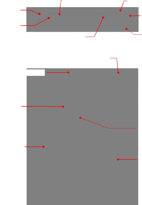
Controls and Components
Control Panel
Unit / Menu Select Button
Pressure / Flow
Rate Display
Pressure / Flow
Rate Units
Temperature Display
Reservoir Cap and Fluid Filter Port
Front
Bypass Valve Access Panel
Control Panel
Air Filter
110-392
Temperature Units
Select / Set Knob
Power Button
Ambient / External Temperature Tracking Probe Connection (optional)
Air Filter Access
7
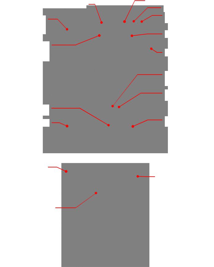
Rear – 230V, 240V, and 208-230V Units
Power Switch / Circuit Breaker
Reservoir Vent (Vent Assembly required on 5XXX models)
IEC Electrical
Connection
Facility Water Outlet (water-cooled models)
Reservoir Drain
Rear – 380V and 460V Units
Vent Assembly (supplied with 5XXX models)
Electrical Connections
Junction Box f
110-392
Communications Port (optional)
RS-232 Port (optional)
Remote Temperature
Probe Port (optional)
Fluid Inlet (from process)
Fluid Outlet (to process)
Over-Temperature Protection Adjust (5XXX models only)
Over-Temperature Protection
Reset (5XXX models only)
Facility Water Inlet (water-cool models)
Power Switch
8
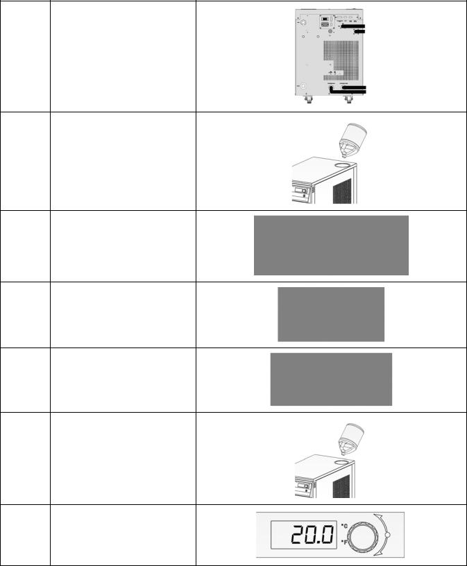
Quick Start
See Installation & Startup for additional information.
All units:
Connect process lines
1Water-cooled units:
A.Connect process lines
B.Connect facility water lines
C.Turn facility water ON
2Fill reservoir with coolant
3Connect electrical power to Mains
4Turn Power Switch / Circuit Breaker ON
5Turn Controller ON
6Add coolant to reservoir as process lines fill
7Enter temperature set point
110-392 |
9 |
Installation and Startup
WARNING: Be sure all power is off before proceeding.
Site Requirements
Ambient Temperature and Relative Humidity
The Chiller is designed for indoor installation in ambient temperatures between 16° and 35°C (60° and 95°F); relative humidity should not exceed 80% (non-condensing).
Location
The Chiller should be installed on a strong, level surface. It should be located as close to possible to the process requiring cooling. It should not be installed closer than 4 feet (1.4 meters) to a heat-generating source, such as heating pipes, boilers, etc. If possible, the Chiller should be located near a suitable drain to prevent flooding in the event of leaks. Do not place it where corrosive fumes, excessive moisture, excessive dust, or high room temperatures are present.
For ease of positioning and maneuverability, the Chiller is supplied with casters. The front wheels can be locked to keep the Chiller in place while in use.
To help prevent voltage drops, position the Chiller as close as possible to the power distribution panel. Avoid voltage drops by using a properly grounded power source wired to meet electrical data plate requirements. The use of an extension cord is not recommended.
NOTE: The Chiller may be located at a level below that of the equipment being cooled. As long as the process remains closed, overflow will not occur when adding cooling fluid to the Chiller reservoir.
Clearance
Adequate clearance should be allowed on the front, sides, and rear of the Chiller for access to connections and components. The front and rear vents of the Chiller must be a minimum of 24 inches (61 cm) away from walls or vertical surfaces so air flow is not restricted.
110-392 |
10 |
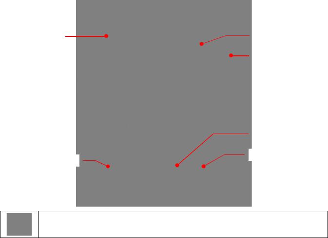
External Piping
Reservoir Vent |
Process Fluid Inlet |
(shown with Vent |
|
Assembly for |
Process Fluid Outlet |
5XXX models)) |
Facility Water Inlet
Facility Water Outlet
Reservoir Drain
WARNING: All facility water connections must be made by a licensed plumber.
General Considerations
To maintain a safe workplace and avoid leaks, special care should be taken when choosing hoses and connectors for the Chiller. It is the user’s responsibility to ensure that the tubing and fittings connected to the Chiller are compatible with the fluid, temperature, and pressure being used.
•Take care when selecting hoses and connections for the Chiller. All external piping, tubing, or hoses should be run full size to limit the potential for external pressure drops. The use of quick-connect fittings is not recommended, as they can cause substantial pressure drops.
•Materials of construction should be compatible with the fluid being used as well as the temperature and pressure at which the unit will operate.
•Where applicable, always use a back-up wrench when making piping connections to the Chiller.
•Pressure Ratings – Hoses should be able to withstand the highest pressure that they will encounter (100 psi / 6.9 bar).
•Flexible Tubing – Avoid tubing that will expand and increase fluid volume when operating at the desired pressure.
•Hose Diameter – The fittings on the Chiller’s process fluid lines are female 0.5 in NPT. The facility water fluid inlets and outlets on water-cooled models are female 0.75 inch NPT.
•Facility Water (water-cooled models only) – Should be clean and well maintained. Ideally, the facility water should be tested monthly to ensure a pH level between 7.2 and 7.8. Add algaecide if algae growth is present.
110-392 |
11 |

Process Fluid Connections
The Chiller has two internally threaded (0.5 inch ID NPT) fittings on the rear of the instrument housing for the process water connections. Two sets of adapters (0.5 inch ID and 0.625 inch ID) are supplied with the unit for connecting these fittings to the process piping.
Connect the Chiller’s inlet and outlet to the external apparatus with hoses or pipes. The direction of the flow through the system can be controlled by the way the connections are made. Fluid is drawn into the Chiller through the “Inlet” connection; fluid is pumped out of the Chiller through the “Outlet” connection.
NOTE: When Chillers with the standard magnetic drive centrifugal pump are connected to an external apparatus with a built-in shutoff, an external bypass loop assembly (Part No. 510-147) may be needed if operating below 20°C (68°F). This bypass assembly continues flow circulation to and from the pump even though the main flow to the external apparatus has been blocked.
Facility Water Connections
WARNING: The incoming cooling water pressure should be 20 psi / 1.4 bar minimum and 150 psi / 10.3 bar maximum.
Water-cooled Chillers have two internally threaded (0.75 inch ID NPT) on the rear of the instrument housing for the facility water connections. The cooling water supply should be connected to the facility water inlet on the Chiller. The facility water outlet on the Chiller should be connected to the appropriate return or drain, as required.
The cooling water supply may be from city tap water or a cooling tower. The incoming water pressure should be between 20 and 150 psi / 1.4 and 10.3 bar.
Reservoir Drain
A 0.5 inch NPT connection is provided for the reservoir’s gravity drain. It should be piped to a drain or receptacle positioned below the bottom of the reservoir. If a receptacle is used, be sure it is of sufficient volume to hold all the coolant in the reservoir, process, and process lines.
Reservoir Vent
A reservoir vent assembly is provided with Chillers equipped with the heater option. This vent relieves pressure within the reservoir as coolant heats and expands. A 0.5 inch NPT connection is provided on the rear of the Chiller for connecting the vent assembly.
110-392 |
12 |

Process Coolant
Suitable Fluids
WARNING: Only use fluids that will satisfy safety, health, and equipment compatibility requirements. Caustic, corrosive, or flammable fluids must never be used.
The Chiller is designed to accommodate a variety of coolant fluids (water, glycol mixtures, etc). For most applications above 15°C (59°F), distilled water is satisfactory. For operation below 15°C (59°F), the Chiller must be protected with an antifreeze solution. Ethylene glycol (laboratory grade) and water in a 50/50 mixture is satisfactory from +15° to -15°C (59° to 5°F). Select a fluid that is compatible with the Chiller’s wetted parts (brass, bronze, stainless steel, EPDM rubber, nylon, PVC).
WARNING: Do not use caustic, corrosive, or flammable fluids.
WARNING: Operation below 15°C (59°F) requires antifreeze in the circulation fluid. DO NOT use automotive antifreeze as the additives may be harmful to the Chiller’s wetted parts.
CAUTION: Do not use the following fluids:
•Automotive antifreeze with additives**
•Hard tap water**
•Deionized water with a specific resistance > 1 meg ohm (except units with the DI water compatible plumbing
•Any flammable fluids
•Concentrations of acids or bases
•Solutions with halides: chlorides, fluorides, bromides, iodides or sulfur
•Bleach (Sodium Hypochlorite)
•Solutions with chromates or chromium salts
•Glycerin
•Syltherm fluids
**At temperatures above 40°C, additives or mineral deposits can adhere to the heater. If deposits are allowed to build up, the heater may overheat and fail. Higher temperatures and higher concentrations of additives can hasten deposit build up.
110-392 |
13 |

Electrical Power
Use the voltage and amperage requirements specified on the data plate on the back of the unit.
Connect the power cord (if) supplied with the Chiller to an appropriate electrical outlet. Avoid voltage drops by using properly grounded power outlets. If possible, locate the Chiller close to the power distribution panel or outlet.
Phase Requirements (if applicable)
For 3-phase units, be sure to connect in proper sequence, ie.: L1, L2, and L3. These Chillers are designed with a junction box on the rear of the unit to which you can connect the electrical power supply conduit. Be sure to provide suitable conduit strain relief and grounding.
3-phase units are equipped with a phase monitor that prevents startup if phase sequence is incorrect. It will also turn the Chiller off in the event of a loss of one phase and/or prevent Chiller operation if there is a voltage mismatch between any two phases greater than 8%.
You can minimize low line voltage problems by eliminating the use of extension cords or long supply conduits.
WARNING:
Make sure electrical connections comply with all applicable electrical codes.
Ground the Chiller in accordance with NEC Article 250.
Operation voltage must be within 10% of the data plate rating.
WARNING: DO NOT apply power to the Chiller until the unit is ready for Startup.
Optional Signal Inputs/Outputs
Ambient / External Temperature Probe
This option allows you to control the cooling fluid temperature using an external temperature measurement (ambient room/machine temperature or process temperature). A 9-pin connector is provided on either the underside of the front control panel or on the rear panel for connecting the ambient/external tracking probe.
NOTE: In order for the Chiller to properly recognize the presence of the external temperature probe, the probe must be connected to the unit before power is applied.
RS-232 / RS-485 Serial Output
This option allows you to remotely control the Chiller and/or output temperature readings to an external recorder or other auxiliary device. The maximum communications distance for Chillers equipped with the RS232 option is 50 feet (15 meters). The maximum distance for units equipped with the RS485 option is 4000 feet (1200 meters). A 9-pin D-connector is provided on the rear of the instrument enclosure for this connection.
Remote On / Off Port
This option allows you to connect a remote on/off switch or other remote control device to the Chiller. A 15-pin D- connector is provided on the rear of the instrument enclosure for this connection. See Appendix, Options for wiring information.
4-20mA Set Point Control
This option allows you to change set point per customer supplied current value. A 15-pin D-connector is provided on the rear of the instrument enclosure for this connection. See Appendix, Options for wiring information.
110-392 |
14 |
 Loading...