


Operator’s Manual
Refrigerated Recirculating Chillers
110-240 06.13.11
Table of Contents
Introduction.............................................................................................................................................................. |
3 |
General Information................................................................................................................................................. |
4 |
General Safety Information .................................................................................................................................... |
4 |
Safety Recommendations...................................................................................................................................... |
4 |
Unpacking Your Chiller .......................................................................................................................................... |
5 |
Regulatory and Compliance Testing...................................................................................................................... |
5 |
Contents................................................................................................................................................................. |
5 |
Controls and Components ..................................................................................................................................... |
6 |
Quick Start................................................................................................................................................................ |
7 |
Installation and Startup........................................................................................................................................... |
8 |
Site Requirements ................................................................................................................................................. |
8 |
Ambient Temperature and Relative Humidity .................................................................................................... |
8 |
Location .............................................................................................................................................................. |
8 |
Clearance ........................................................................................................................................................... |
8 |
Electrical Power ..................................................................................................................................................... |
8 |
Optional Signal Inputs/Outputs .............................................................................................................................. |
9 |
External Ambient Tracking Temperature Probe................................................................................................. |
9 |
RS232 / RS485 Serial Output ............................................................................................................................ |
9 |
Remote I/O Port.................................................................................................................................................. |
9 |
Plumbing ................................................................................................................................................................ |
9 |
Process Piping.................................................................................................................................................... |
9 |
Reservoir Drain................................................................................................................................................... |
9 |
External Water Filter........................................................................................................................................... |
9 |
Closed Sytem or Cooling Coil Setup.................................................................................................................... |
10 |
Open Bath System Setup .................................................................................................................................... |
10 |
Startup.................................................................................................................................................................. |
10 |
Process Coolant ............................................................................................................................................... |
10 |
Electrical Power................................................................................................................................................ |
11 |
Starting Process Fluid Flow.............................................................................................................................. |
11 |
Normal Operation .................................................................................................................................................. |
13 |
Selecting the Temperature Unit ........................................................................................................................... |
13 |
Displaying and Adjusting the Set Point................................................................................................................ |
13 |
Displaying and Adjusting the Ambient Tracking Offset........................................................................................ |
13 |
Displaying and Adjusting the Remote Control Temperature ............................................................................... |
14 |
Selecting the Pressure / Flow Rate Display and Units ........................................................................................ |
14 |
Selecting the Internal / External Temperature Display ........................................................................................ |
14 |
Setting Operational Parameters........................................................................................................................... |
15 |
High Temperature Limit (HL)............................................................................................................................ |
16 |
Low Temperature Limit (LL) ............................................................................................................................. |
16 |
High Ambient Temperature Limit (HA) ............................................................................................................. |
16 |
Maximum Fluid Pressure (FP).......................................................................................................................... |
16 |
Minimum Flow Rate (FL) .................................................................................................................................. |
17 |
Maximum External / Internal Temperature Differential (Sd)............................................................................. |
17 |
Auto-Refrigeration Temperature (AF)............................................................................................................... |
18 |
Remote Probe (rP) ........................................................................................................................................... |
18 |
Internal Calibration Offset (c1) ......................................................................................................................... |
19 |
External Calibration Offset (c2) ........................................................................................................................ |
19 |
Baud Rate (PC) ................................................................................................................................................ |
20 |
Display, Alarm and Error Messages .................................................................................................................... |
20 |
Adjusting the High Pressure Bypass Setting ..................................................................................................... |
23 |
Enabling / Disabling the Local Lockout .............................................................................................................. |
23 |
Routine Maintenance and Troubleshooting ....................................................................................................... |
24 |
Routine Maintenance ........................................................................................................................................... |
24 |
Standard Magnetic Drive Centrifugal Pump..................................................................................................... |
24 |
Condenser, Air Vents and Reusable Filter....................................................................................................... |
24 |
110-240 |
1 |
Fluid Filter......................................................................................................................................................... |
24 |
Fluid Level ........................................................................................................................................................ |
24 |
Temperature Calibration................................................................................................................................... |
24 |
Troubleshooting ................................................................................................................................................... |
25 |
Diagnostic Mode .................................................................................................................................................. |
26 |
Technical Information ........................................................................................................................................... |
27 |
General Specifications (all Chillers)..................................................................................................................... |
27 |
Pump Performance .............................................................................................................................................. |
27 |
Performance Specifications – 60Hz Chillers........................................................................................................ |
28 |
1/4-HP, 1/3-HP and 1/2-HP Chillers................................................................................................................. |
28 |
3/4-HP and 1-HP Chillers ................................................................................................................................. |
30 |
Performance Specifications – 50Hz Chillers........................................................................................................ |
32 |
1/4-HP, 1/3-HP and 1/2-HP Chillers................................................................................................................. |
32 |
3/4-HP and 1-HP Chillers ................................................................................................................................. |
34 |
Diagrams and Schematics.................................................................................................................................... |
36 |
Electrical Wiring Diagram..................................................................................................................................... |
36 |
Flow Schematic.................................................................................................................................................... |
37 |
Replacement Parts ................................................................................................................................................ |
38 |
RS232 Communications ....................................................................................................................................... |
40 |
Equipment Disposal (WEEE Directive)................................................................................................................ |
41 |
Service and Technical Support ............................................................................................................................ |
41 |
Warranty ................................................................................................................................................................. |
42 |
110-240 |
2 |
Introduction
Your Recirculating Chiller provides cooling power for demanding applications and serves as an economical alternative to tap water cooling systems. Extremely easy to use and maintain, it combines technological innovation with precise temperature control to deliver reliable heat removal for a wide variety of applications.
Here are some of the features that make your Chiller so user-friendly:
•Microprocessor-based temperature controller
•Large, easy to read digital temperature display (°C or °F)
•One-touch temperature set point adjustment
•Digital pressure/flow rate display (PSI, kPa, GPM, LPM) with push-button selection
•Cool Command™ modulated refrigeration system for enhanced temperature stability and extended compressor life
•Centrifugal, positive displacement, or regenerative turbine pump
It will take you very little time to get your Recirculating Chiller installed and running. This manual is designed to guide you quickly through the process. We recommend that you read it thoroughly before you begin.
110-240 |
3 |
General Information
General Safety Information
When installed, operated, and maintained according to the directions in this manual and common safety procedures, your Chiller should provide safe and reliable heat removal. Please ensure that all individuals involved in the installation, operation, or maintenance of this unit read this manual thoroughly prior to working with the unit.
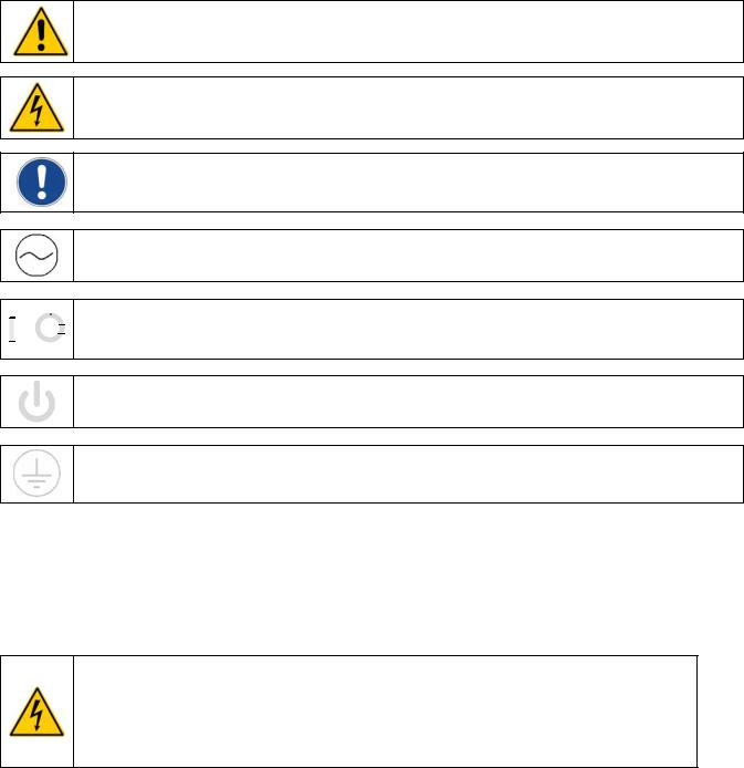
This symbol alerts you to wide range of potential dangers.
This symbol advises you of danger from electricity or electric shock.
This symbol marks information that is particularly important.
This symbol indicates alternating current.
/ |
These symbols on the Power Switch / Circuit Breaker indicate that they place the main power supply ON / OFF. |
|
This symbol on the Power Switch indicates that it places the unit in a standby mode. It DOES NOT fully disconnect the unit from the power supply.
This symbol indicates a protective conductor terminal.
Read all instructions pertaining to safety, set-up, and operation.
Proper operation and maintenance is the user’s responsibility.
Safety Recommendations
To prevent injury to personnel and/or damage to property, always follow your workplace’s safety procedures when operating this equipment. You should also comply with the following safety recommendations:
•Always connect the power cord on this unit to a grounded (3-prong) power outlet. Make certain that the outlet is the same voltage and frequency as your unit.
•Never operate the unit with a damaged power cord.
•Always turn the unit OFF and disconnect Mains power before performing any maintenance or service.
110-240 |
4 |

Unpacking Your Chiller
Your Chiller is shipped in a special carton. Retain the carton and all packing materials until the unit is completely assembled and working properly. Set up and run the unit immediately to confirm proper operation. Beyond one week, your unit may be warranty repaired, but not replaced. If the unit is damaged or does not operate properly, contact the transportation company, file a damage claim and contact the company where your unit was purchased immediately.
CAUTION: Keep unit upright when moving. Be sure to follow your company’s procedures and practices regarding the safe lifting and relocation of heavy objects.
Regulatory and Compliance Testing
CSA UL (60Hz units)
CAN/CSA C22.2 No. 61010-1-04 — Safety Requirements for Electrical Equipment for Measurement, Control and Laboratory Use, Part I: General Requirements.
CAN/CSA C22.2 No. 61010-010-04 — Safety Requirements for Electrical Equipment for Measurement, Control and Laboratory Use - Part 2-010: Particular Requirements for Laboratory Equipment for the Heating of Materials.
UL Std No. 61010-1 — Electrical Equipment for Laboratory Use, Part I: General Requirements.
UL Std No. 61010A-2-010 — Electrical Equipment for Laboratory Use, Part 2: Particular Requirements for Laboratory Equipment for the Heating of Materials.
CE (50Hz units)
EC Low Voltage Directive 2006/95/EC
EC Electromagnetic Compatibility Directive 2004/108/EC IEC 61010-1-2001
IEC 61326:2005 / EN 61326 : 2006
Highly Accelerated Life Test (HALT) and Vibration Tests per ASTM D4169-8 (All units)
Contents
The following items have been included with your Chiller:
•Operator’s Manual
•IEC Power Cord
•Two sets of Inlet/Outlet Adapters: ½ inch male NPT, 5/8 inch male NPT
110-240 |
5 |
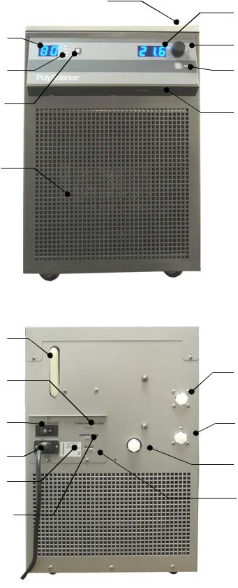
Controls and Components
Reservoir Cap and Fluid Filter Port
(top rear)
Pressure / Flow Rate Display
Pressure / Flow Rate Units
Units / Menu Select Button
Air Filter
Reservoir Fluid
Level Gauge
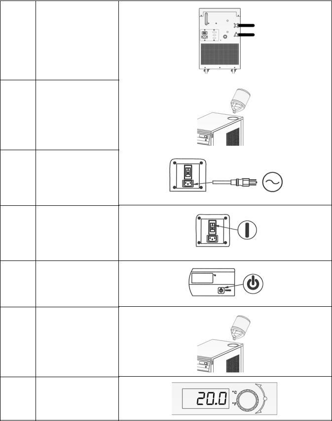
Remote I/O
Connection
(optional)
Circuit Breaker /
Power Switch
IEC Power Connection
Identification Label
Ambient Tracking / Remote
Temperature Probe
Connection (optional)
Temperature Display
Select/Set Knob
Power Button
Ambient Tracking / Remote
Temperature Probe
Connection (optional)
Fluid Outlet
Fluid Inlet
Drain
RS232 / RS485
Connection (optional)
110-240 |
6 |
Quick Start
See Installation & Startup for additional information.
1 Connect all process lines
2Fill reservoir with coolant
3Connect electrical power cord to Mains
4Turn Power Switch / Circuit Breaker ON
5Turn Controller ON
6Add coolant to reservoir as process lines fill
7Enter temperature set point
110-240 |
7 |
Installation and Startup
WARNING: Be sure all power is off before proceeding.
Site Requirements
Ambient Temperature and Relative Humidity
The Chiller is designed for indoor installation in ambient temperatures between 5° and 30°C (41° and 86°F); relative humidity should not exceed 80% (non-condensing).
Location
The Chiller should be installed on a strong, level surface. It should be located as close to possible to the process requiring cooling. It should not be installed closer than 4 feet (1.4 meters) to a heat-generating source, such as heating pipes, boilers, etc. If possible, the Chiller should be located near a suitable drain to prevent flooding in the event of leaks. Do not place it where corrosive fumes, excessive moisture, excessive dust, or high room temperatures are present.
For ease of positioning and maneuverability, the Chiller is supplied with casters. The front wheels can be locked to keep the Chiller in place while in use.
To help prevent voltage drops, position the Chiller as close as possible to the power distribution panel. Avoid voltage drops by using a properly grounded power outlet wired with 14 gauge or larger diameter wire. The use of an extension cord is not recommended.
NOTE: The Chiller may be located at a level below that of the equipment being cooled. As long as the process remains closed, overflow will not occur when adding cooling fluid to the Chiller reservoir.
Clearance
Adequate clearance should be allowed on the front, sides, and rear of the Chiller for access to connections and components. The front and rear vents of the Chiller must be a minimum of 24 inches (61 cm) away from walls or vertical surfaces so air flow is not restricted.
Electrical Power
An IEC power cord is provided with the Chiller. It should be attached to the receptacle on the rear of the enclosure. Make sure that the power outlet used for the Chiller is properly grounded and matches the voltage and frequency indicated on the identification label on the back of the Chiller.
The use of an extension cord is not recommended. However, if one is necessary, it must be properly grounded and capable of handling the total wattage of the unit. The extension cord must not cause more than a 10% drop in voltage to the Chiller.
WARNING: DO NOT plug the Chiller into the electrical outlet until the unit is ready for startup (see Startup).
110-240 |
8 |

Optional Signal Inputs/Outputs
External Ambient Tracking Temperature Probe
This option allows you to control the cooling fluid temperature using an external temperature measurement (ambient room/machine temperature or process temperature). A 9-pin connector is provided on either the underside of the local control panel or on the rear panel for connecting the external probe.
NOTE: In order for the Chiller to properly recognize the presence of the external temperature probe, the probe must be connected to the unit before power is applied.
RS232 / RS-485 Serial Output
This option allows you to remotely control the Chiller and/or output temperature readings to an external recorder or other auxiliary device. The maximum communications distance for Chillers equipped with the RS232 option is 50 feet (15 meters). The maximum distance for units equipped with the RS485 option is 4000 feet (1200 meters). A 9-pin D-connector is provided on the rear of the instrument enclosure for this connection.
Remote I/O Port
This option allows you to use an external 12 VDC signal or a dry contact closure to turn the Chiller on and off. Chiller status is also available from this port. A 15-pin D-connector is provided on the rear of the instrument enclosure for this connection. See schematic at the end of this manual.
Plumbing
Process Piping
The Chiller has two internally threaded (1/2 inch ID NPT) fittings on the rear of the instrument housing for the process water connections. Two sets of adapters (1/2 inch ID and 5/8 inch ID) are supplied with the unit for connecting these fittings to the process piping.
To maintain a safe workplace and avoid leaks, special care should be taken when choosing hoses and connectors for the Chiller. It is the user’s responsibility to ensure that the tubing and fittings connected to the Chiller are compatible with the fluid, temperature, and pressure being used.
Pressure Ratings — Hoses should be able to withstand the largest pressure that they will encounter.
For “P” Series (positive displacement pump) and “T” Series (turbine pump) Chillers, this is 100 psi (689 kPa).
Flexible Tubing — Avoid tubing that will expand and take up fluid volume when operating at the desired pressure.
Hose Diameter — Process piping/hosing with a diameter smaller than ½ inch ID can be used if desired. However, keep in mind that using smaller diameter hosing increases pressure in the circulating system.
Couplings and Clamps — The use of screw-tightened hose clamps is necessary on all joints to insure good, tight connections. Quick connectors are not recommended as they have the potential for restricting flow rate.
Reservoir Drain
A ½ inch NPT connection is provided for the reservoir’s gravity drain. It should be piped to a drain or receptacle positioned below the bottom of the reservoir. If a receptacle is used, be sure it is of sufficient volume to hold all the water in the reservoir, process, and process lines.
External Water Filter
An optional water filter is available that can be connected to the Chiller’s fluid inlet or fluid outlet. Consult supplier for additional information.
110-240 |
9 |
Closed System or Cooling Coil Setup
Connect the Chiller’s inlet and outlet to the external apparatus with hoses or pipes. The direction of the flow through the system can be controlled by the way the connections are made. Fluid is drawn into the Chiller through the “Inlet” connection; fluid is pumped out of the Chiller through the “Outlet” connection.
NOTE: When Chillers with the standard magnetic drive centrifugal pump are connected to an external apparatus with a built-in shutoff, an external bypass loop assembly (Cat. No. 510-147) may be needed if operating below 20°C (68°F). This bypass assembly continues flow circulation to and from the pump even when the main flow to the external apparatus is blocked.
Open Bath System Setup
Position the external tank at least two feet (0.6 meter) above the Chiller’s inlet.
Install a shutoff valve on both the inlet and outlet of the Chiller. Place the valves in the closed position.
Connect the shutoff valves to the external tank using the tubing of equal diameter (1/2 inch minimum) and length. Use the same size fittings on both the inlet and outlet; this will ensure a balanced flow.
Cut the external end of the suction (inlet) tube into a “V” shape so that the tube will not seal itself against the wall of the external tank. Both the pressure and suction tubing should be securely fastened to the external tank to prevent movement during use. When using flexible tubing, the suction (inlet) tubing must have a wall thickness that will not collapse under vacuum, particularly when going around bends.
Fill the external bath (see Startup, Process Coolant for suitable fluids).
Fill the Chiller reservoir to the top of the filler neck and install the filter screen and cap. Tighten the cap until it is securely sealed.
Startup
Process Coolant
Suitable Fluids
WARNING: Only use fluids that will satisfy safety, health, and equipment compatibility requirements. Caustic, corrosive, or flammable fluids must never be used.
The Chiller is designed to accommodate a variety of coolant fluids (water, glycol mixtures, etc). For most applications above 20°C (68°F), distilled water is satisfactory. For operation at or below 20°C (68°F), the Chiller must be protected with an antifreeze solution. Ethylene glycol (laboratory grade) and distilled water in a 50/50 mixture is satisfactory from +20° to -15°C (68° to 5°F). Select a fluid that is compatible with the Chiller’s wetted parts (brass, stainless steel, polyethylene, EPDM rubber, and nylon).
WARNING: Do not use caustic, corrosive, or flammable fluids.
WARNING: Operation below 20°C (68°F) requires antifreeze in the circulation fluid.
WARNING: FOR CHILLERS WITH MAGNETIC DRIVE PUMPS ONLY: A low temperature fluid, such as a mixture of 50% ethylene or propylene glycol / 50% distilled water, or equivalent, must be used under all operating conditions.
110-240 |
10 |

WARNING: Do not use the following fluids:
•Automotive antifreeze with additives**
•Hard tap water**
•Deionized water with a specific resistance > 1 meg ohm (except units with the DI water compatible plumbing
•Any flammable fluids
•Concentrations of acids or bases
•Solutions with halides: chlorides, fluorides, bromides, iodides or sulfur
•Bleach (Sodium Hypochlorite)
•Solutions with chromates or chromium salts
•Glycerin
•Syltherm fluids
•** At temperatures above 40°C, additives or mineral deposits can adhere to the heater. If deposits are allowed to build up, the heater may overheat and fail. Higher temperatures and higher concentrations of additives can hasten deposit build up.
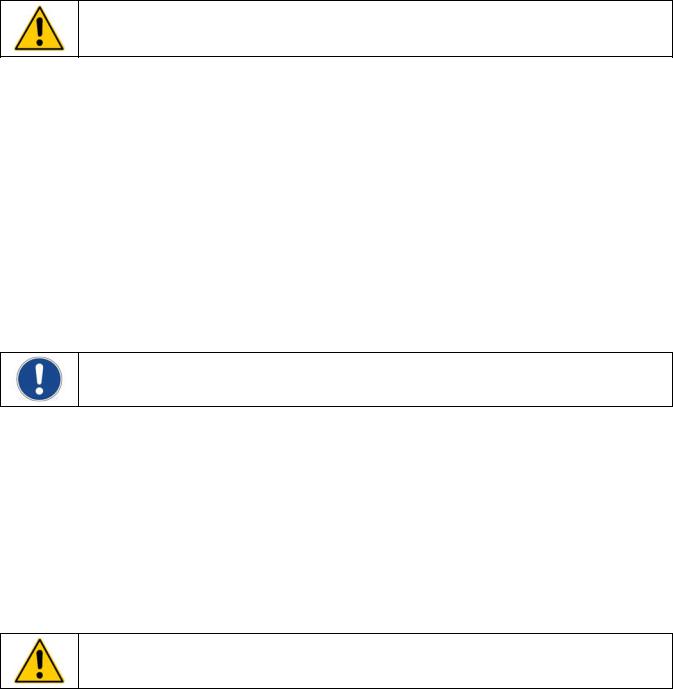
Filling the Reservoir
Remove the filler cap from the reservoir and, using a funnel, add fluid until it reaches the MAX line on the reservoir’s fluid level gauge. Once the reservoir is full, remove the funnel but do not replace the cap at this time.
Electrical Power
Plug the Chiller’s power cord into an appropriate electrical outlet.
Place the Circuit Breaker/Power Switch on the rear of the instrument enclosure in the “On” position. Three decimal points will appear on the Temperature display; two decimal points will appear on the pressure/flow rate display.
. . |
|
. . . |
|
|
|
Starting Process Fluid Flow
Press the Power Button on the front panel. The system startup sequence will begin and proceed as follows:
1.The pump will turn on and fluid will begin circulating through the system. The set point temperature will appear briefly on the Temperature display; after a few seconds, it will be replaced by the actual fluid temperature. Fifteen to twenty seconds after power up, the compressor will begin operating.
2.Check for leaks.
3.With the pump running, the reservoir’s fluid level will drop as the process and/or process cooling lines fill with fluid. Add fluid as follows:
4.Closed Systems: Slowly add fluid to the reservoir until the liquid level remains stable.
4.Open Bath Systems:
A.Set the flow alarm to at least 4 LPM (see “Minimum Flow Rate”)
B.Open the inlet and outlet valves on the Chiller; the suction created by the pump should begin drawing fluid through the inlet tubing into the Chiller reservoir.
C.Once flow is established (no air bubbles in inlet tubing), close the inlet and outlet valves and turn the Chiller ‘off’.
D.Remove the reservoir cap and check the level of the fluid in the reservoir. Add coolant until it is level with the top of the filler neck.
CAUTION: Always close the inlet and outlet valves before turning power to the Chiller ‘off’ or removing the reservoir cap to prevent the external reservoir from flooding the Chiller.
110-240 |
11 |

E.Replace the reservoir cap, open the inlet and outlet valves, and restart the Chiller.
F.Observe the liquid level in the external reservoir; adjust the valve on the Chiller outlet as required to maintain a stable fluid level.
CAUTION: When running an open loop system for extended periods, the fluid level in the Chiller reservoir should be checked periodically to avoid low fluid conditions.
To check the reservoir fluid level, close the inlet and outlet valves, turn the Chiller ‘off’, and remove the reservoir cap. Slowly open the inlet and outlet valves and allow fluid to drain from the external reservoir into the Chiller reservoir. Close the valves when the fluid level within the Chiller reservoir reaches the top of the filler neck. Add fluid to the external reservoir as required. Replace the reservoir cap, open the inlet and outlet valves, and turn the Chiller back on.
110-240 |
12 |
 Loading...