


PolyScience AP07R-20, AP07R-40, AP7LR-20, AP15R-30, AP15R-40 Operating Manual
...Circulating Baths with Advanced Programmable Temperature
Controller
Operator’s Manual
Models:
AP07R-20
AP07R-40
AP7LR-20
AP15R-30
AP15R-40
AP20R-30
AP28R-30
AP45R-20
AP07H200
AP15H200
AP20H200
AP28H200
AP06S150
AP10S150
AP20S150
AP28S150
AP08P100
AP11P100
AP14P100
AP17P100
AP23P100
AP28P100
AP29VB3S
AP29VB5R
110-514 PSC/EN 06.08.11
Table of Contents |
|
Introduction ................................................................................................................................................. |
4 |
Circulating Baths with Advanced Programmable Temperature Controller............................................... |
4 |
General Safety Information....................................................................................................................... |
5 |
Safety Recommendations......................................................................................................................... |
6 |
Regulatory Compliance & Testing ............................................................................................................ |
7 |
Unpacking Your Circulator........................................................................................................................ |
8 |
Contents ................................................................................................................................................... |
8 |
Controls & Components............................................................................................................................ |
9 |
Advanced Programmable Controller .................................................................................................... |
9 |
Refrigerating/Heating Baths ............................................................................................................... |
10 |
Heating Only Baths............................................................................................................................. |
11 |
Open Bath Systems (Stainless Steel) ................................................................................................ |
12 |
Open Bath Systems (Polycarbonate)................................................................................................. |
12 |
Viscosity Bath (Polycarbonate) .......................................................................................................... |
13 |
Quick-Start................................................................................................................................................. |
14 |
Installation & Startup................................................................................................................................ |
15 |
General Site Requirements .................................................................................................................... |
15 |
Adding Liquid to the Bath Reservoir ....................................................................................................... |
16 |
Pump Inlet and Outlet Connections........................................................................................................ |
17 |
External Closed Loop Circulation ........................................................................................................... |
17 |
Open Loop Circulation............................................................................................................................ |
18 |
Refrigeration Control Connections (Refrigerating/Heating Circulators only).......................................... |
19 |
Electrical Power ...................................................................................................................................... |
19 |
Refrigerating / Heating Circulators ..................................................................................................... |
19 |
Heat Only Circulators and Open Bath Systems ................................................................................. |
20 |
Communication....................................................................................................................................... |
21 |
USB Communication .......................................................................................................................... |
22 |
Ethernet .............................................................................................................................................. |
22 |
RS232 / RS485 Serial Communication .............................................................................................. |
22 |
External (P2) Temperature Probe .......................................................................................................... |
22 |
Controller Setup ........................................................................................................................................ |
23 |
Power...................................................................................................................................................... |
23 |
Safety Set Temperature.......................................................................................................................... |
23 |
Basic Operation......................................................................................................................................... |
25 |
Turning Your Circulator On..................................................................................................................... |
25 |
Controller & Touch Screen Navigation ................................................................................................... |
25 |
Controller Navigation.......................................................................................................................... |
25 |
Touch Screen Navigation ................................................................................................................... |
25 |
Menu Structure ....................................................................................................................................... |
27 |
Main Operational Displays (Home Screens) .......................................................................................... |
28 |
Status Bar........................................................................................................................................... |
28 |
Home Screens.................................................................................................................................... |
29 |
Adjusting the Temperature Set Point...................................................................................................... |
30 |
General Operational Settings ................................................................................................................. |
32 |
Pump Speed....................................................................................................................................... |
33 |
Unit ..................................................................................................................................................... |
33 |
Sound ................................................................................................................................................. |
33 |
Language............................................................................................................................................ |
33 |
Display................................................................................................................................................ |
33 |
Lock Out ............................................................................................................................................. |
33 |
Auto Restart........................................................................................................................................ |
33 |
Personalize......................................................................................................................................... |
33 |
110-514 PSC/EN |
1 |
Display Filter....................................................................................................................................... |
34 |
SHC (Specific Heat Capacity) ............................................................................................................ |
34 |
Time and Date Settings .......................................................................................................................... |
34 |
Time.................................................................................................................................................... |
34 |
Date .................................................................................................................................................... |
34 |
Safety Settings........................................................................................................................................ |
35 |
High Limit / Low Limit Temperatures.................................................................................................. |
35 |
High Alarm / Low Alarm Temperatures .............................................................................................. |
35 |
Control .................................................................................................................................................... |
36 |
Probe Control ..................................................................................................................................... |
36 |
Auto Cool............................................................................................................................................ |
36 |
Fluid Type........................................................................................................................................... |
37 |
P2 - P1................................................................................................................................................ |
37 |
PID...................................................................................................................................................... |
37 |
External Cooling Control .................................................................................................................... |
38 |
Send Internal Data USB/WEB............................................................................................................ |
38 |
Reset Memory and Reboot ................................................................................................................ |
38 |
Communications and Data Logging ....................................................................................................... |
38 |
Ethernet .............................................................................................................................................. |
38 |
RS232................................................................................................................................................. |
39 |
USB .................................................................................................................................................... |
39 |
RS485................................................................................................................................................. |
39 |
Timer....................................................................................................................................................... |
40 |
Enabling / Disabling the Local Lock Out................................................................................................. |
41 |
Advanced Operation ................................................................................................................................. |
42 |
Time/Temperature Programming ........................................................................................................... |
42 |
Creating a Temperature Program ...................................................................................................... |
42 |
Previewing a Program ........................................................................................................................ |
45 |
Running a Program ............................................................................................................................ |
46 |
Editing a Program............................................................................................................................... |
47 |
Saving and Uploading Programs........................................................................................................ |
48 |
Event Scheduling.................................................................................................................................... |
51 |
Creating and Installing a Personalized Home Screen............................................................................ |
53 |
Circulator Monitoring and Control Using an Internet Browser................................................................ |
54 |
Calibration.................................................................................................................................................. |
55 |
Restoring All Factory Default Values...................................................................................................... |
57 |
System Restoration .................................................................................................................................. |
57 |
Changing Your Circulator's Viewing Angle............................................................................................ |
58 |
Inert Gas Purge ......................................................................................................................................... |
58 |
Tap Water Cooling .................................................................................................................................... |
58 |
Reservoir Cover Storage.......................................................................................................................... |
59 |
Routine Maintenance & Troubleshooting............................................................................................... |
60 |
Service Sub-Menu .................................................................................................................................. |
60 |
Diagnostic Data Logging......................................................................................................................... |
61 |
Maintaining Clear Bath Water................................................................................................................. |
61 |
Draining the Bath Reservoir ................................................................................................................... |
62 |
Checking the Over-Temperature / Low Liquid Level Safety Systems.................................................... |
63 |
Cleaning Your Circulator......................................................................................................................... |
64 |
Temperature Controller Removal and Re-Installation ............................................................................ |
65 |
Removal ............................................................................................................................................. |
65 |
Re-Installation..................................................................................................................................... |
66 |
Calibrating the Touch Screen ................................................................................................................. |
67 |
Display Module Firmware Updates......................................................................................................... |
67 |
110-514 PSC/EN |
2 |
Warning and Fault Messages................................................................................................................. |
68 |
Warnings ............................................................................................................................................ |
68 |
Faults.................................................................................................................................................. |
69 |
Troubleshooting Chart ............................................................................................................................ |
70 |
Technical Information............................................................................................................................... |
72 |
Performance Specifications.................................................................................................................... |
72 |
Reservoir Fluids...................................................................................................................................... |
74 |
Application Notes.................................................................................................................................... |
76 |
Tubing and Fitting Temperature Ranges................................................................................................ |
76 |
Fluid Compatibility .................................................................................................................................. |
76 |
RS232/RS485 Communications............................................................................................................. |
77 |
USB Data Logging.................................................................................................................................. |
79 |
USB B Setup, Monitoring, and Control................................................................................................... |
79 |
Ethernet Configuration............................................................................................................................ |
80 |
Direct Computer to Controller Configuration ...................................................................................... |
80 |
Wired or Wireless Network Configuration .......................................................................................... |
80 |
TCP Control Configuration ................................................................................................................. |
82 |
External Cooling Control......................................................................................................................... |
83 |
Equipment Disposal (WEEE Directive) ................................................................................................... |
85 |
Replacement Parts & Accessories.......................................................................................................... |
86 |
PolyScience Circulating Bath Fluids ...................................................................................................... |
88 |
Service & Technical Support ................................................................................................................... |
89 |
Warranty..................................................................................................................................................... |
89 |
110-514 PSC/EN |
3 |

Introduction
Thank you for choosing this Circulating Bath with Advanced Programmable Temperature Controller. It is intended for the precise temperature control of suitable liquids in a reservoir. Extremely easy to use and maintain, it combines design innovation with highly intuitive operation to deliver convenient and versatile liquid temperature control for a wide range of applications.
WARNING: PolyScience Circulating Baths are not intended for directly controlling the temperature of foods, pharmaceuticals, medicines, or other objects which may be ingested by or injected in humans or animals. Any such objects must be isolated from contact with the bath fluid and bath surfaces.
Here are some of the features that make your Circulating Bath so user-friendly:
Intuitive touch screen operation Time/temperature programming
Selection of seven different temperature displays, including time-temperature graphing Powerful variable-speed pressure/suction pump with external circulation capability 180° viewing radius (Swivel 180™ rotating control head)
DuraTop™ heat and chemical resistant top plate
LidDock™ self-storing reservoir cover (integrated baths only) Built-in temperature protection
Suitable for use with Class III flammable bath fluids per DIN 12876-1
It will take you very little time to get your new Circulating Bath installed and running. This Operator’s Manual is designed to guide you quickly through the process. We recommend that you read it thoroughly before you begin.
Circulating Baths with Advanced Programmable Temperature Controller
Model Type |
Reservoir |
Temperature Range |
||
Capacity |
°C |
°F |
||
|
||||
|
|
|
|
|
AP07R-20 Refrigerating/Heating |
7 liter |
-20° to 200°C |
-4° to 392°F |
|
|
|
|
|
|
AP07R-40 Refrigerating/Heating |
7 liter |
-40° to 200°C |
-40° to 392°F |
|
AP7LR-20 Refrigerating/Heating |
7 liter |
-20° to 200°C |
-4° to 392°F |
|
|
|
|
|
|
AP15R-30 Refrigerating/Heating |
15 liter |
-30° to 200°C |
-22° to 392°F |
|
|
|
|
|
|
AP15R-40 Refrigerating/Heating |
15 liter |
-40° to 200°C |
-40° to 392°F |
|
|
|
|
|
|
AP20R-30 Refrigerating/Heating |
20 liter |
-30° to 200°C |
-22° to 392°F |
|
AP28R-30 Refrigerating/Heating |
28 liter |
-30° to 200°C |
-22° to 392°F |
|
|
|
|
|
|
AP45R-20 Refrigerating/Heating |
45 liter |
-25° to 135°C (1) |
-13° to 275°F (1) |
|
AP07H200 Heating Only |
7 liter |
Ambient +10° to 200°C |
Ambient +20° to 392°F |
|
|
|
|
|
|
AP15H200 Heating Only |
15 liter |
Ambient +10° to 200°C |
Ambient +20° to 392°F |
|
AP20H200 Heating Only |
20 liter |
Ambient +10° to 200°C |
Ambient +20° to 392°F |
|
|
|
|
|
|
AP28H200 Heating Only |
28 liter |
Ambient +10° to 200°C |
Ambient +20° to 392°F |
|
|
|
|
|
|
AP06S150 Stainless Steel Open Tank |
6 liter |
Ambient +10° to 150°C (2) |
Ambient +20° to 302°F (2) |
|
AP10S150 Stainless Steel Open Tank |
10 liter |
Ambient +10° to 150°C (2) |
Ambient +20° to 302°F (2) |
|
AP20S150 Stainless Steel Open Tank |
20 liter |
Ambient +10° to 150°C (2) |
Ambient +20° to 302°F (2) |
|
AP28S150 Stainless Steel Open Tank |
28 liter |
Ambient +10° to 150°C (2) |
Ambient +20° to 302°F (2) |
|
AP08P100 Polycarbonate Open Tank |
8 liter |
Ambient +10° to 85°C (3) |
Ambient +20 to 185°F (3) |
|
AP11P100 Polycarbonate Open Tank |
11 liter |
Ambient +10° to 85°C (3) |
Ambient +20 to 185°F (3) |
|
AP14P100 Polycarbonate Open Tank |
14 liter |
Ambient +10° to 85°C (3) |
Ambient +20 to 185°F (3) |
|
AP17P100 Polycarbonate Open Tank |
17 liter |
Ambient +10° to 85°C (3) |
Ambient +20 to 185°F (3) |
|
AP23P100 Polycarbonate Open Tank |
23 liter |
Ambient +10° to 85°C (3) |
Ambient +20 to 185°F (3) |
|
110-514 PSC/EN |
4 |

AP28P100 Polycarbonate Open Tank |
28 liter |
Ambient +10° to 85°C (3) |
Ambient +20 to 185°F (3) |
AP29VB3S Polycarbonate Viscosity |
29 liter |
Ambient +10° to 85°C (3) |
Ambient +20 to 185°F (3) |
AP29VB5R Polycarbonate Viscosity |
29 liter |
Ambient +10° to 85°C (3) |
Ambient +20 to 185°F (3) |
1.Maximum operating temperature at which ±0.01°C temperature stability can be maintained; Advanced Programmable Controller is capable of higher temperatures.
2.Maximum operating temperature for stainless steel tank. Advanced Programmable Controller is capable of higher temperatures.
3.Maximum operating temperature for polycarbonate tank. Advanced Programmable Controller is capable of higher temperatures.
General Safety Information
When installed, operated, and maintained according to the directions in this manual and common safety procedures, your Circulating Bath should provide safe and reliable temperature control. Please ensure that all individuals involved in the installation, operation, or maintenance of this Circulating Bath read this manual thoroughly prior to working with the unit.
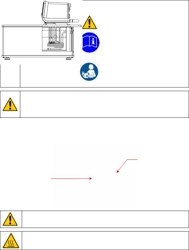
This symbol alerts you to a wide range of potential dangers.
This symbol advises you of danger from electricity or electric shock.
This symbol indicates that a hot surface may be present.
This symbol marks information that is particularly important.
This symbol indicates alternating current.
/These symbols on the Power Switch / Circuit Breaker indicate that they place the main power supply ON / OFF.
This symbol on the Power Key indicates that it places the unit in a standby mode. It DOES NOT fully disconnect the unit from the power supply.
Read all instructions pertaining to safety, set-up, and operation.
Proper operation and maintenance is the user’s responsibility.
110-514 PSC/EN |
5 |
Safety Recommendations
To prevent injury to personnel and/or damage to property, always follow your workplace’s safety procedures when operating this equipment. You should also comply with the following safety recommendations:
WARNING:
This Circulating Bath is suitable for use with Class III flammable fluids per DIN 12876-1. A fire hazard may be present.
Be aware of the chemical hazards that may be associated with the bath fluid used. Observe all safety warnings for the fluids used as well as those contained in the material safety data sheet.
Explosive gas mixtures may accumulate if used with insufficient ventilation. Use this Circulating Bath in a well ventilated area or beneath a suitable fume hood only.
Use only recommended bath fluids; see Technical Information in the rear of this manual for recommended fluids.
Use only non-acid bath fluids.
WARNING: When using Class III flammable fluids per DIN 12876-1, the user must attach the following warning labels to the front of the unit so that they are well visible:
Warning Label |
|
Danger Area. |
W09 |
|
Attention! Observe instructions |
Colors: Yellow/black |
|
(operating manual, safety data sheet) |
|
|
|
Mandatory Label |
|
Carefully read the user information prior to |
M018 |
|
beginning operation. |
Colors: Blue/white |
|
Scope: EU |
or |
|
|
Semi S1-0701 |
|
Carefully read the user information prior to |
Table A1-2 #9 |
|
beginning operation. |
Colors: Blue/white |
|
Scope: NAFTA |
|
|
|
WARNING:
Always connect the power cord on this Circulator to a grounded (3-prong) power outlet. Make certain that the outlet is the same voltage and frequency as your unit.
Never operate the Circulator with a damaged power cord.
Always turn the Circulator OFF and disconnect mains power before performing any maintenance or service.
WARNING:
Never operate the Circulator without bath fluid in the reservoir. Periodically check the reservoir to ensure that the liquid depth is within acceptable levels. Always refill the reservoir using the same bath fluid type that is already in the reservoir. Bath oil must not contain any water contaminants and should be preheated to the actual bath temperature before adding as there is an explosion hazard at high temperatures.
Always drain all fluid from the reservoir before moving or lifting your Circulator. Be sure to follow your organization’s procedures and practices regarding the safe lifting and relocation of heavy objects.
110-514 PSC/EN |
6 |
WARNING:
Always allow the bath fluid to cool to ambient temperature before draining.
The reservoir cover, top deck, and/or external pump connections may become hot with continuous use. Exercise caution when touching these parts.
Always keep within the 85°C maximum operating temperature limit if using a polycarbonate tank.
WARNING: It is the user’s responsibility to properly decontaminate the unit in the event hazardous materials are spilled on exterior or interior surfaces. Consult manufacturer if there is any doubt regarding the compatibility of decontamination or cleaning agents.
Regulatory Compliance & Testing
This equipment is compliant with the European Directive 2002/95/EC and its latest amendments on Restrictions on Hazardous Substances (RoHS) and below the given limits of hazardous substances.
ETL Intertek (60 Hz units)
UL 61010-1 / CSA C22.2 No. 61010-1 — Safety Requirements for Measurement, Control, and Laboratory Use; Part 1: General Requirements
UL 61010A-2-010 / CSA C22.2 No. 61010-2-010:04 — Safety Requirements for Measurement, Control, and Laboratory Use; Part 2-010: Particular Requirements for Laboratory Equipment for the Heating of Materials
UL 61010A-2-051 / CSA C22.2 No. 61010-2-051:04 — Safety Requirements for Measurement, Control, and Laboratory Use; Part 2-051: Particular Requirements for Laboratory Equipment for the Mixing and Stirring
CE (all units)
EC Low Voltage Directive 2006/95/EC
EC Electromagnetic Compatibility Directive 2004/108/EC IEC 61010-1-2001
IEC 61010-2-2001
IEC 61326:2005 / EN 61326 : 2006
110-514 PSC/EN |
7 |
Unpacking Your Circulator
Your Circulator was packed in a special carton or cartons. You should keep the packaging, along with all packing materials, until the unit has been installed and you are certain it is working properly.
CAUTION: Remove any loose packing material that may have fallen into the heater/pump housing during shipping. Before powering up, check that nothing remains around the heater or Circulator pump.
We recommend that you begin using your Circulator immediately to confirm proper operation, since beyond one week you may be eligible for warranty repair only (rather than replacement). You’ll find complete warranty information in the back of this manual.
WARNING: Keep unit upright when moving. Be sure to follow your company’s procedures and practices regarding the safe lifting and relocation of heavy objects.
Contents
The items included with your Circulator will vary depending on which model Circulating Bath you purchased.
|
Refrigerating / |
Heating Only |
Open Bath |
|
|
Heating Bath |
Bath |
System |
|
Resource Disk with |
● |
● |
● |
|
Operator’s Manual |
||||
|
|
|
||
Reservoir Cover |
● |
● |
● |
|
|
|
|
|
|
3-ft / 0.91 m IEC to |
● |
|
|
|
IEC Power Cord |
|
|
||
|
|
|
||
6-ft / 1.82 m IEC to |
● |
● |
● |
|
Mains Power Cord |
||||
|
|
|
||
Refrigeration Control |
● |
|
|
|
Cable |
|
|
||
|
|
|
||
|
|
1/4 in. NPT to 3/16 in. barbed adapter (1) |
||
Fittings |
|
1/4 in. NPT to 1/4 in. barbed adapter (1) |
||
|
1/4 in. NPT to 3/8 in. barbed adapter (1) |
|||
|
|
¼ in. NPT to M16 barbed adapter (2) |
||
Cooling Coil |
N/A |
Integral |
Optional |
|
|
|
|
|
|
Certificate of |
● |
● |
● |
|
Compliance |
||||
|
|
|
||
Quick-Start Guide |
● |
● |
● |
|
|
|
|
|
|
1.60Hz and 50Hz models
2.50Hz models only
Viscosity
Bath
●
●
●
Integral
●
●
110-514 PSC/EN |
8 |

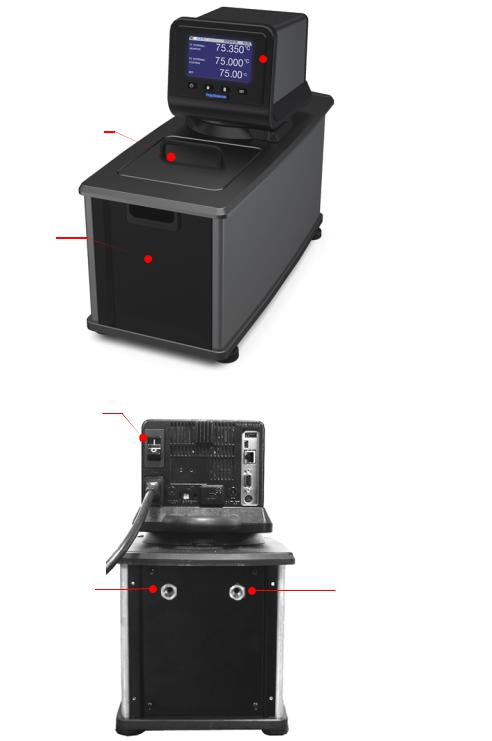
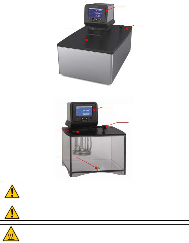
Controls & Components
Advanced Programmable Controller
SmartTouch™ Touch
Screen Display
Power Key
Home Key
Menu Key
Power Switch /
Circuit Breaker (located on Refrigeration Power Module on Refrigerating/Heating Circulators)
Safety Set
Thermostat
IEC Electrical
Connection
IEC Power Cord
Fluid Inlet
Connection
Inert Gas Injection Port
110-514 PSC/EN
Set Key
Swivel 180™
Latch Release
USB A Connection
USB B Connection
Ethernet Connection
RS232/RS485
Serial Port
External (P2)
Temperature Probe
Connection
Refrigeration Control
Connection (functional on
Refrigerating/Heating
Circulators only)
Fluid Outlet Connection
Bypass Tubing
9
Refrigerating/Heating Baths
Reservoir Drain Valve and Port (behind access panel)
Side access on AP7LR-20)
Washable Air Filter (behind access panel)
IEC Power Connection to
Refrigeration Module
Refrigeration Power
Module
Power Switch / Circuit Breaker
Power |
Cooling |
Cooling Fault
Fan
Cooling System Status Display
110-514 PSC/EN
Advanced Programmable
Temperature Controller
Reservoir Cover
Drain Valve and Port
(right side on AP7LR-20 only)
Refrigeration
Control Connection
Refrigeration Control
Connection
IEC Power Connection to Controller
IEC Electrical Connection to Mains
10
Heating Only Baths
Reservoir Cover
Reservoir Drain and Port
(behind access panel)
Power Switch / Circuit Breaker
IEC Power Connection to Mains 
Tap Water Cooling
Connection (inlet)
110-514 PSC/EN
Advanced Programmable
Controller
Tap Water Cooling
Connection (outlet)
11
Open Bath Systems (Stainless Steel)
Reservoir Cover
Open Bath Systems (Polycarbonate)
Reservoir Cover
Drain Port (17, 23 and 28 liter baths only
Advanced Programmable
Controller
Cooling Coil Deck Opening (10, 20 and 28 liter models)
Advanced Programmable Controller
Cooling Coil Deck Opening (17, 23 and 28 liter models)
WARNING: The top deck on Open Bath Systems is not attached. Do not remove deck while Circulator is operating. Do not lift bath by grasping the Temperature Controller or top deck. Always disconnect electrical power and drain fluid from bath before moving.
WARNING: The PolyScience Advanced Programmable Temperature Controller is designed for use with Class III flammable liquids per DIN 12876-1; however, we strongly recommend that Open Bath Systems be used only with non-flammable fluids.
WARNING: To avoid the potential for burns, allow the Circulator to cool completely before cleaning or performing any maintenance.
110-514 PSC/EN |
12 |
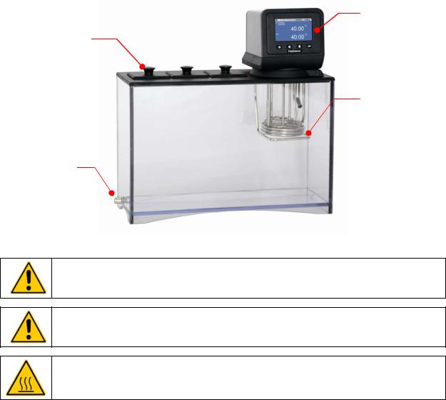
Viscosity Bath (Polycarbonate)
Advanced
Programmable
Lidded Viscometer Controller
Openings
Tap Water
Cooling Coil
Drain
WARNING: The top deck on Viscosity Baths is not attached. Do not remove deck while Circulator is operating. Do not lift bath by grasping the Temperature Controller or top deck. Always disconnect electrical power and drain fluid from bath before moving.
WARNING: The PolyScience Advanced Programmable Temperature Controller is designed for use with Class III flammable liquids per DIN 12876-1; however, we strongly recommend that Viscosity Baths be used only with non-flammable fluids.
WARNING: To avoid the potential for burns, allow the Circulator to cool completely before cleaning or performing any maintenance.
110-514 PSC/EN |
13 |
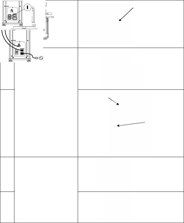
Quick-Start
Unless otherwise specified, quick-start instructions apply to all models.
See Installation & Startup for additional information.
Maximum: 1 in. / 2.54 cm below underside of top deck
1 Fill reservoir with fluid
 Minimum: 3.0 in. / 7.6 cm below underside of top deck
Heating only models
2A
Connect all electrical power cords |
IEC power cord |
Refrigerating / Heating |
|
from Controller |
|
models |
|
and control cables |
to Refrigeration |
|
|
|
|
||
|
Power Module |
|
|
|
|
|
|
2B |
|
|
Refrigeration control |
|
|
cable |
|
|
|
|
|
|
|
|
|
Heating only models
3A
Place Power Switch / Circuit Breaker in ON position
Refrigerating / Heating models
3B
110-514 PSC/EN |
14 |
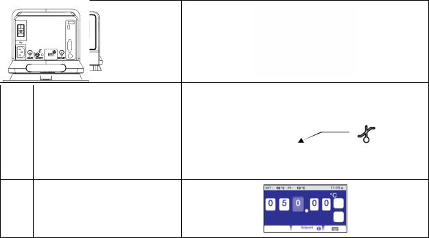
4 Turn Controller “ON”
5 |
Set safety thermostat |
|
|
|
|
||
|
|
|
|
6 Set Temperature Set Point
Installation & Startup
Your Circulating Bath with Advanced Programmable Temperature Controller is designed to be simple to set-up and install. The only tools required are a Philips-head screwdriver and a container for adding water or other suitable fluid to the bath reservoir.
General Site Requirements
Locate your Circulator on a level surface free from drafts and direct sunlight. Do not place it where there are corrosive fumes, excessive moisture, high room temperatures, or in excessively dusty areas.
Refrigerating / Heating Circulators must be 10.2 cm / 4 inches or more away from walls or vertical surfaces so that airflow is not restricted.
Avoid voltage drops by using properly grounded power outlets wired with 14 gauge or larger diameter wire and if possible, be close to the power distribution panel. The use of extension cords is not recommended; this will reduce the potential for problems caused by low line voltage.
110-514 PSC/EN |
15 |
Adding Liquid to the Bath Reservoir
WARNING: When using Class III flammable fluids per DIN 12876-1, the user must attach the following warning labels to the front of the unit so that they are well visible:
Warning Label |
|
Danger Area. |
W09 |
|
Attention! Observe instructions |
Colors: Yellow/black |
|
(operating manual, safety data sheet) |
|
|
|
Mandatory Label |
|
Carefully read the user information prior to |
M018 |
|
beginning operation. |
Colors: Blue/white |
|
Scope: EU |
or |
|
|
Semi S1-0701 |
|
Carefully read the user information prior to |
Table A1-2 #9 |
|
beginning operation. |
Colors: Blue/white |
|
Scope: NAFTA |
|
|
|
WARNING: Read the safety data sheet for the bath fluid being used carefully before filling reservoir. WARNING: See Technical Information in the rear of this manual for a list of compatible liquids.
WARNING: If the proper fluid level is not maintained, the heater coil may become exposed and possibly damaged (fluid level too low) or the bath may overflow (fluid level too high).
The liquid in the reservoir should be maintained at a depth between 1 inch / 2.54 cm and 3.0 inches / 7.6 cm below the underside of the bath’s top deck. Upon start up, it may be necessary to add fluid to the bath to compensate for the fluid required for external circulation. Likewise, be sure to compensate for fluid displacement when placing samples or other materials in the Circulator’s reservoir.
Maximum Fluid Level = 1 inch / 2.54 cm below underside of top deck
Minimum Fluid Level = 3.0 inches / 7.6 cm below underside of top deck
WARNING: Always drain all fluid from the reservoir before moving or lifting your Circulator. Be sure to follow your organization’s procedures and practices regarding the safe lifting and relocation of heavy objects.
WARNING: To avoid the potential for burns, allow the Circulator to cool completely before cleaning or performing any maintenance.
110-514 PSC/EN |
16 |

Pump Inlet and Outlet Connections
WARNING: When connecting tubing to an external application, it is the user’s responsibility to make sure that the tubing and fittings connected to the Circulator are suitable for the fluid being used and the temperature range of operation.
CAUTION: The Circulator’s bypass tubing is secured to the fluid inlet and outlet connections by high temperature nylon hose clamps, which can be removed by carefully cutting them with diagonal cutters.
CAUTION: Secure the tubing to the inlet and outlet fittings using hose clamps with a minimum ID of 7/8 inch (22 mm). Do not operate the unit without hose clamps.
WARNING: If the Circulating Bath will not be used for external circulation, the inlet and outlet ports should remain connected using the Buna N bypass tubing provided with the unit.
The pump inlet and outlet ports are female ¼ inch NPT connections that permit use of barbed tubing adapters or hard plumbing fittings. ½ inch (13mm) ID tubing may also be slid over these connections and held in place with a hose clamp.
If the pump inlet and outlet are not used for external circulation, the Bypass Tubing provided with the unit should be left in place in order to optimize fluid mixing within the reservoir.
The nylon barbed tubing adapter fittings supplied with the unit are intended for applications from
-40° to 93°C. For applications above 93°C, brass, stainless steel, or Teflon® fittings are recommended. ¼ inch NPT to M16 stainless steel male adapter fittings are provided with all 50Hz models.
NOTE: The use of quick-connect fittings is not recommended as they typically restrict flow rate.
External Closed Loop Circulation
Connect the pump inlet and outlet to the external apparatus. To maintain adequate flow, avoid restrictions in the tubing. When connecting the Circulator to more than two closed loops, the use of a manifold made of “Y” adapters to divide the fluid into multiple banks is recommended. After setting up multiple closed loops, check for adequate flow at the return manifold of each loop and check that the bath fluid is at an adequate level. A booster pump may be added to closed loops without damaging the Circulator’s pump.
The temperature control stability of a closed loop system is better at the external apparatus than in the Circulator reservoir (provided the control point of the apparatus represents a constant load and is well insulated). For example, if you circulate fluid through a viscometer at 50°C, the temperature variation observed in the Circulator reservoir may be ±0.1°C while the temperature variation in the viscometer may be only ±0.05°C.
Although temperature stability is generally better at the external apparatus control point, depending on the length of tubing used and the efficiency of the insulation, the actual temperature reading at the external apparatus may be slightly different than the temperature reading at the Circulator reservoir.
110-514 PSC/EN |
17 |
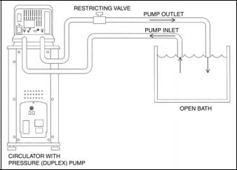
Open Loop Circulation
The duplex (pressure/suction) pump permits circulation to and from an external open bath. To prevent siphoning when the Circulating Bath is turned off, position both baths so that the two fluid levels are at the same elevation.
Connect the pump inlet and outlet to the external bath using tubing of the same diameter and length. The same size fittings should also be used on both the inlet (suction) and outlet (pressure). This helps ensure a balanced flow. A restricting valve or pinch clip should be installed in the pressure (outlet) tubing and adjusted to match the return suction (inlet) flow rate. Cut the external end of the suction tube into a “V” shape so that the tube will not seal itself against the wall of the external tank. Both the pressure and suction tubing should be securely fastened to the external tank to prevent movement during use.
When using flexible tubing, the suction tubing must have a wall thickness that will not collapse under vacuum, particularly when going around bends.
Circulating Bath Height Regulation — Position the ends of the pressure and suction tubes at the desired maximum fluid level in the external bath and fill the bath to that level. Fill the Circulating Bath to a height one inch (25mm) below the top of the reservoir. Start the pump and adjust the restricting valve/pinch clip on the outlet tubing until the liquid height in both baths remains constant. Add fluid to the baths as needed to compensate for the fluid in the inlet and outlet lines.
110-514 PSC/EN |
18 |
Refrigeration Control Connections (Refrigerating/Heating Circulators only)
Refrigeration Control
Connection
Refrigeration Control
Cable
Refrigeration Control
Connection
Electrical Power
WARNING: The Circulator’s power cord must be connected to a properly grounded electrical receptacle. Make certain that this electrical outlet is the same voltage and frequency as your Circulator. The correct voltage and frequency for your Circulator are indicated on the identification label on the back of the Controller.
CAUTION: The use of an extension cord is not recommended. If one is necessary, it must be properly grounded and capable of handling the total wattage of the unit. The extension cord must not cause more than a 10% drop in voltage to the unit.
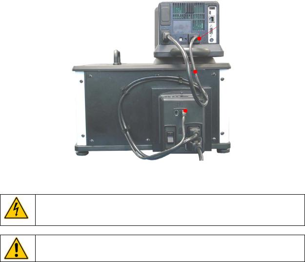
Refrigerating / Heating Circulators
Attach the 3-ft / 0.91 m power cord to the IEC electrical connectors on the Temperature Controller (male) and the Refrigeration Power Module (female).
Attach the 6-ft / 1.8 m power cord to the IEC electrical connection on the Refrigeration Power Module and then plug the male connector into the Mains electrical outlet.
Place the Power Switch / Circuit Breaker on the Refrigeration Power Module in the ON position. An hour glass will appear on the Temperature Controller’s display while the Circulator completes an initialization sequence. Once completed, “Standby” will appear on the display; the Power Key will also light.
110-514 PSC/EN |
19 |
IEC Power Connection to
Refrigeration Power Module
IEC to IEC Power Cord 
Refrigeration
Power Module
Power Switch /
Circuit Breaker IEC Power
Connection to
Controller
IEC Power Connection to Mains
IEC to Mains Power Cord
Heat Only Circulators and Open Bath Systems
Attach the 6-ft / 1.8 m power cord to the IEC electrical connection on the Temperature Controller and then plug the male connector into the Mains electrical outlet.
Place the Power Switch / Circuit Breaker on the Temperature Controller in the ON position. The display on the Controller will light and “Standby” will appear on the display; the Power Key will also light.
110-514 PSC/EN |
20 |
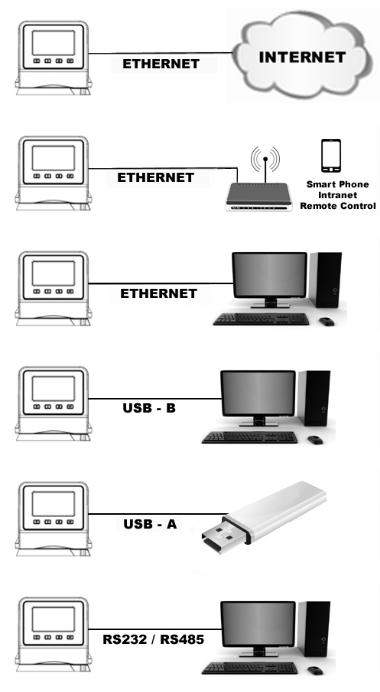
Communication
The Advanced Programmable Controller features a variety of connectivity options. Following are some typical ways you can use them to monitor and control the operation of your Circulator.
110-514 PSC/EN |
21 |
USB Communication
Two USB ports (A and B) are provided on the rear of the Temperature Controller for use with USB flash drives to log temperature data and store and/or transfer time/temperature programs. See Basic Operation, Communications and Data Logging for more information.
Ethernet
An Ethernet port is provided on the back of the Temperature Controller to enable you to connect your Circulator to a computer network.
RS232 / RS485 Serial Communication
CAUTION: Always turn electrical power to the Circulator OFF before making a connection to the serial (DB9) port.
Your Circulator features RS232 / RS485 serial communication for remote data logging and control capability. A DB9 connector is provided on the rear of the Temperature Controller for this purpose. See
Basic Operation, Communications and Data Logging for set up information.
The serial interface should be connected to a serial communication port on a remote PC using an appropriate cable. Information on the RS232 / RS485 commands and communication protocol can be found in the Technical Information section of this manual.
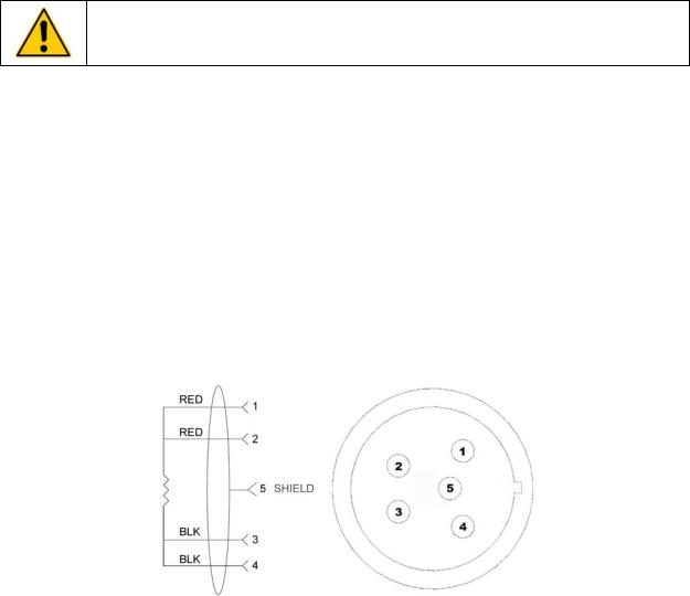
External (P2) Temperature Probe
Your Circulator is capable of controlling temperature based on either the temperature of the internal bath or that of an external vessel or device. The connection for the optional external temperature probe is on the rear of the Temperature Controller. The Temperature Controller automatically detects the external temperature probe when it is connected. See Replacement Parts & Accessories for available lengths and part numbers.
Pin Out Diagrams — External (P2) Temperature Probe Connection
RTD SENSOR: 4 WIRE CIRCUIT, 100 OHMS @ 0 DEGREES C,
MAXIMUM OPERATING TEMPERATURE @ 200 C, CLASS A 0.003850 OHMS/DEGREES C.
110-514 PSC/EN |
22 |
Controller Setup
Power
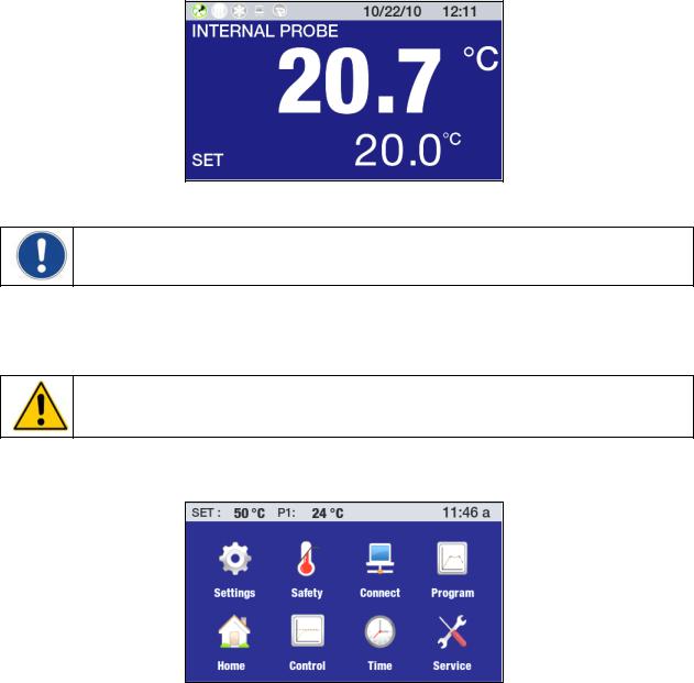
Press  . “Initializing” will appear briefly on the display, the Circulator will begin running, and the default Main Run screen will appear.
Safety Set Temperature
NOTE: The Safety Set Temperature is displayed and set in whichever temperature unit is currently selected. The default is °C. To set the temperature using °F, see General Operational Settings, Unit.
This is a “Do Not Exceed” temperature setting for your Circulator and is the temperature at which the heater will be turned OFF should the liquid level in the bath drop too low or the heater malfunctions. It is normally set about 5° higher than the desired operating temperature. Setting the Safety Set Temperature is a simple 4-step procedure.
WARNING: The Safety Thermostat is user-adjustable from approximately 40° to 240°C / 104° to 464°F. Do not force the indicator dial beyond the stops at either end of the dial’s range.
1. Press  to access the Main menu.
2. Touch the Safety icon to access the Safety sub-menu.
110-514 PSC/EN |
23 |
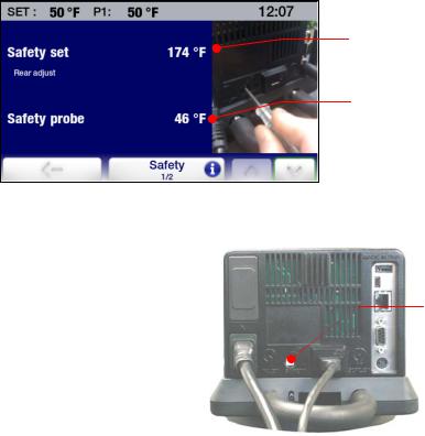
3.Using a small, Philips head screwdriver, rotate the Safety Set Thermostat on the rear of the Temperature Controller until the desired Safety Set Temperature is displayed (clockwise to increase; counter-clockwise to decrease).
4.Press the icon or the  key to return to the Main Menu.
110-514 PSC/EN
Safety Set
Temperature
Current Safety Probe reading
Safety Set
Thermostat

24
Basic Operation
Turning Your Circulator On
Press the  key.
key.
The Circulator will begin running and the Main Operational Display (Home) will appear.
Controller & Touch Screen Navigation
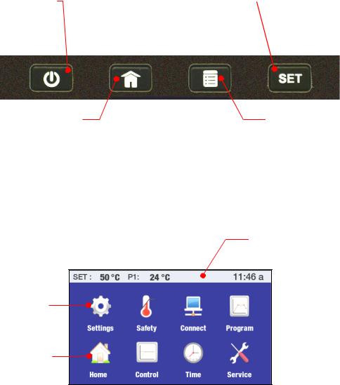
Controller Navigation
POWER –
Turns the Circulator’s
Temperature Controller ON
and OFF.
HOME --
Returns the to the Main Operational Display (Home) from any screen
Toggles through available
Home screens.
SET --
Used in conjunction with various screen icons and buttons to change the set point temperature
MENU --
Accesses the Temperature Controller’s Main Menu (from any screen)
Touch Screen Navigation
Main Menu
Press  to access.
Status Bar – Appears on all screens
Accesses associated sub-menu
Return to Main Run screen (Home screen)
110-514 PSC/EN |
25 |
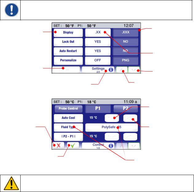
Sub-Menus
NOTE: The following examples are intended to illustrate how commonly used touch screen icons function when displayed. A specific icon may or may not be displayed on a sub-menu page. The function/operation of icons not shown here are described in the sections associated with the screens on which they appear.
Sub-Menu Item -- Toggles between available choices
Previous Menu
Information –
Help regarding sub-menu items
Cancel -- Cancels change to a setting
Accept --
Accepts change to a setting
Current Setting (white letters on blue field)
Alternate Setting
(blue letters on white field)
Next Page
Previous Page
Decreases Value
Increases Value
Current Setting (more than two settings available) – Touch to access other available selections
CAUTION: The menu and sub-menu screens time-out and revert to the Main Operational Display (Home Screen) after approximately 30 seconds without any touch screen interaction. Any changes made will take effect automatically.
110-514 PSC/EN |
26 |
 Loading...