


ENGLISH | FRANÇAIS
Pressure Cleaner
Booster Pump
Installation and
Operation Manual
For Polaris PB4-60 Booster Pumps with Serial Numbers beginning with "PB" and a manufacturing date on or after Dec 1, 2011.
H0344400 REVD
 WARNING
FOR YOUR SAFETY - This product must be installed and serviced by a contractor who is licensed and qualified in pool equipment by the jurisdiction in which the product will be installed, where such state or local requirements exist. In the event no such state or local requirement exists, the maintainer must be a professional with sufficient experience in pool equipment installation and maintenance, so that all of the instructions in this manual can be followed exactly. Improper installation and/or operation can create dangerous electrical hazards, which can cause high voltages to run through the electrical system. Before installing this product, read and follow all warning notices and instructions that accompany this product. Failure to follow warning notices and instructions may result in property damage, personal injury, or death. Improper installation and/or operation will void the warranty.
If these instructions are not followed exactly, a fire or explosion may result, causing property damage, personal injury, or death.
ATTENTION INSTALLER: This manual contains important information about the installation, operation and safe use of this product. This information should be given to the owner/operator of this equipment.

Page 2 |
ENGLISH |
Polaris® PB4-60 Booster Pump | Installation and Operation Manual |
Table of Contents
Section 1. IMPORTANT SAFETY INSTRUC- |
|
TIONS.............................................. |
3 |
1.1 Safety Instructions............................................. |
3 |
1.2Pool Pump Suction Entrapment
Prevention Guidelines....................................... |
5 |
Section 2. General Description...................... |
6 |
|
2.1 |
Introduction........................................................ |
6 |
2.2 |
Description......................................................... |
6 |
2.3 |
Preparation........................................................ |
6 |
Section 3. |
Installation...................................... |
6 |
|
3.1 |
Electrical Installation.......................................... |
6 |
|
|
3.1.1 |
Voltage Checks ..................................... |
6 |
|
3.1.2 |
Bonding and Grounding......................... |
6 |
3.2 |
Electrical............................................................ |
6 |
|
|
3.2.1 |
Electrical Wiring..................................... |
7 |
3.3 |
Plumbing............................................................ |
7 |
|
|
3.3.1 |
Requirements......................................... |
7 |
|
3.3.2 |
Pipe Sizing............................................. |
8 |
|
3.3.3 |
Pump Location....................................... |
8 |
|
3.3.4 |
Install the Pump..................................... |
9 |
|
3.3.5 |
Installation Recommendations............... |
9 |
|
3.3.6 Check the Water Flow............................ |
9 |
|
|
3.3.7 |
Conduct Pressure Test........................... |
10 |
Section 4. |
Operation........................................ |
10 |
|
4.1 |
Start-up.............................................................. |
10 |
|
Section 5. |
Maintenance................................... |
11 |
|
5.1 |
Winterizing the Pump........................................ |
11 |
|
Section 6. Troubleshooting and Repair......... |
12 |
||
6.1 |
Troubleshooting................................................. |
12 |
|
6.2 |
Service Technician Maintenance....................... |
13 |
|
|
6.2.1 |
Blocked Impeller..................................... |
13 |
|
6.2.2 |
Impeller Removal................................... |
13 |
|
6.2.3 |
Impeller Replacement............................ |
14 |
|
6.2.4 |
Mechanical Seal Replacement............... |
14 |
|
6.2.5 |
Motor Replacement ............................... |
15 |
Section 7. Product Specifications and Techni- |
|||
|
|
cal Data........................................... |
16 |
7.1 |
Replacement Parts List..................................... |
16 |
|
7.2Polaris PB4-60 Booster Pump Exploded View.. 16
7.3 Pump Dimensions............................................. |
17 |
7.4Visual Identification of the New Polaris PB4-60
Booster Pump.................................................... |
18 |
EQUIPMENT INFORMATION RECORD
DATE OF INSTALLATION
INSTALLER INFORMATION
INITIAL PRESSURE GAUGE READING (WITH CLEAN FILTER)
PUMP MODEL |
|
HORSEPOWER |
NOTES:

Polaris® PB4-60 Booster Pump | Installation and Operation Manual |
ENGLISH |
Page 3 |
Section 1. IMPORTANT SAFETY INSTRUCTIONS
READ AND FOLLOW ALL INSTRUCTIONS
1.1Safety Instructions
All electrical work must be performed by a licensed electrician and conform to all national, state, and local codes. When installing and using this electrical equipment, basic safety precautions should always be followed, including the following:
 WARNING
To reduce the risk of injury, do not permit children to use this product.
 WARNING
To reduce the risk of property damage or injury, do not attempt to change the backwash (multiport, slide, or full flow) valve position with the pump running.
 WARNING
Zodiac® pumps are powered by a high voltage electric motor and must be installed by a licensed or certified electrician or a qualified swimming pool service technician.
 WARNING
RISK OF ELECTRIC SHOCK, FIRE, PERSONAL INJURY, OR DEATH. Connect only to a branch circuit that is protected by a ground-fault circuit-interrupter (GFCI). Contact a qualified electrician if you cannot verify that the circuit is protected by a GFCI. Make sure such a GFCI should be provided by the installer and should be tested on a routine basis. To test the GFCI, push the test button. The GFCI should interrupt power. Push the reset button. Power should be restored. If the GFCI fails to operate in this manner, the GFCI is defective. If the GFCI interrupts power to the pump without the test button being pushed, a ground current is flowing, indicating the possibility
of electrical shock. Do not use the pump. Disconnect the pump and have the problem corrected by a qualified service representative before using.
Due to the potential risk of fire, electric shock, or injuries to persons, Zodiac Pumps must be installed in accordance with the National Electrical Code® (NEC®), all local electrical and safety codes, and the Occupational Safety and Health Act (OSHA®). Copies of the NEC may be ordered from the National Fire Protection Association® (NFPA®) online at www.nfpa.org or call 617-770-3000, or contact your local government inspection agency.
 WARNING
Incorrectly installed equipment may fail, causing severe injury or property damage.
 WARNING
•Do not connect the system to an unregulated city water system or other external source of pressurized water producing pressures greater than 35 PSI.
•Trapped air in system can cause the filter lid to be blown off, which can result in death, serious personal injury, or property damage. Be sure all air is out of the system before operating.
Page 4 |
ENGLISH |
Polaris® PB4-60 Booster Pump | Installation and Operation Manual |
 WARNING
To minimize the risk of severe injury or death the filter and/or pump should not be subjected to the piping system pressurization test.
Local codes may require the pool piping system to be subjected to a pressure test. These requirements are generally not intended to apply to the pool equipment such as filters or pumps.
Zodiac® pool equipment is pressure tested at the factory.
However, if the WARNING cannot be followed and pressure testing of the piping system must include the filter and/or pump, BE SURE TO COMPLY WITH THE FOLLOWING SAFETY INSTRUCTIONS:
•Check all clamps, bolts, lids, lock rings and system accessories to ensure they are properly installed and secured before testing.
•RELEASE ALL AIR in the system before testing.
•Water pressure for test must NOT EXCEED 35 PSI.
•Water temperature for test must NOT EXCEED 100°F (38°C).
•Limit test to 24 hours. After test, visually check system to be sure it is ready for operation.
NOTICE: These parameters apply to Zodiac equipment only. For non-Zodiac equipment, consult equipment manufacturer.
 WARNING
Chemical spills and fumes can weaken pool/spa equipment. Corrosion can cause filters and other equipment to fail, resulting in severe injury or property damage. Do not store pool chemicals near your equipment.
 CAUTION
Do not start pump dry! Running the pump dry for any length of time will cause severe damage and will void the warranty.
 CAUTION
This pump is for use with permanently installed pools and may also be used with hot tubs and spas if so marked. Do not use with storable pools. A permanently installed pool is constructed in or on the ground or in a building such that it cannot be readily disassembled for storage. A storable pool is constructed so that it may be readily disassembled for storage and reassembled to its original integrity.
 CAUTION
Do not install within an outdoor enclosure or beneath the skirt of a hot tub or portable spa. The pump requires adequate ventilation to maintain air temperature at less than the maximum ambient temperature rating listed on the motor rating plate.
SAVE THESE INSTRUCTIONS
Polaris® PB4-60 Booster Pump | Installation and Operation Manual |
ENGLISH |
Page 5 |
1.2Pool Pump Suction Entrapment Prevention Guidelines
 WARNING
Pump suction is hazardous and can trap and drown or disembowel bathers. Do not use or operate swimming pools, spa, or hot tubs if a suction outlet cover is missing, broken, or loose. The following guidelines provide information for pump installation that minimizes the risk of injury to users of pools, spas, and hot tubs:
Entrapment Protection - The pump suction system must provide protection against the hazards of suction entrapment.
Suction Outlet Covers - All suction outlets must have correctly installed, screw-fastened covers in place. All suction outlet (drain) covers must be maintained. Drain covers must be listed/certified to the latest version of ANSI®/ASME® A112.19.8 or its successor standard, ANSI/APSP-16. They must be replaced if cracked, broken, or missing.
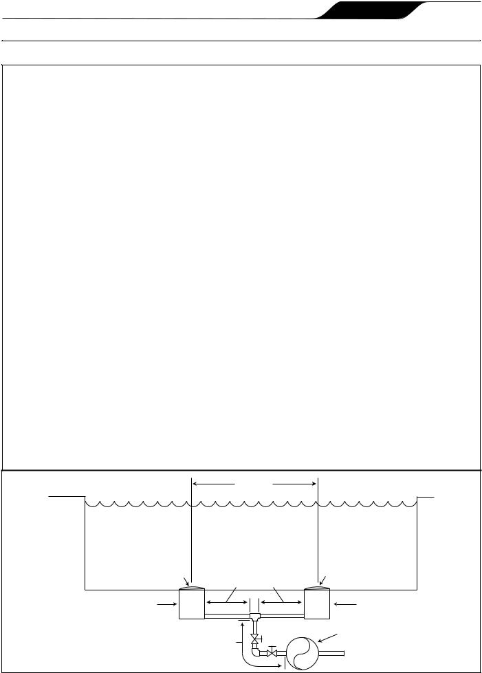
Number of Suction Outlets Per Pump - Provide at least two (2) hydraulically-balanced main drains, with covers, as suction outlets for each circulating pump suction line. The centers of the main drains (suction outlets) on any one (1) suction line must be at least three (3) feet apart, center to center. See Figure 1.
The system must be built to include at least two (2) suction outlets (drains) connected to the pump whenever the pump is running. However, if two (2) main drains run into a single suction line, the single suction line may be
equipped with a valve that will shut off both main drains from the pump. The system shall be constructed such that it shall not allow for separate or independent shutoff or isolation of each drain. See Figure 1.
More than one (1) pump can be connected to a single suction line as long as the requirements above are met.
Water Velocity - The maximum water velocity through the suction fitting or cover for any suction outlet must be 1.5 feet per second unless the outlet complies with the latest version of ANSI/ASME A112.19.8 or its successor standard, ANSI/APSP-16, the standard for Suction Fittings For Use in Swimming Pools, Wading Pools, Spas, and Hot Tubs. In any case, do not exceed the suction fitting’s maximum designed flow rate.
If 100% of the pump’s flow comes from the main drain system, the maximum water velocity in the pump suction hydraulic system must be six (6) feet per second or less, even if one (1) main drain (suction outlet) is completely blocked. The flow through the remaining main drain(s) must comply with the latest version of ANSI/ASME A112.19.8 or its successor standard, ANSI/APSP-16, the standard for Suction Fittings For Use in Swimming
Pools, Wading Pools, Spas, and Hot Tubs.
Testing and Certification - Suction outlet covers must have been tested by a nationally recognized testing laboratory and found to comply with the latest version of ANSI/ASME A112.19.8 or its successor standard, ANSI/
APSP-16, the standard for Suction Fittings For Use in Swimming Pools, Wading Pools, Spas, and Hot Tubs.
Fittings - Fittings restrict flow; for best efficiency use fewest possible fittings (but at least two (2) suction outlets). Avoid fittings which could cause an air trap.
Pool cleaner suction fittings must conform to applicable International Association of Plumbing and Mechanical Officials (IAPMO®) standards.
|
At least |
|
|
three (3) feet |
|
Listed/certified to latest |
|
Listed/certified to latest |
published version of |
|
published version of |
ANSI/ASME A112.19.8 - 2007 |
|
ANSI/ASME A112.19.8 - 2007 |
or its successor, |
|
or its successor, |
ANSI/APSP-16 |
|
ANSI/APSP-16 |
Anti-entrapment |
|
Anti-entrapment |
Cover/Grate or Suction |
No valves between |
Cover/Grate or Suction Fitting, |
Fitting, screw-fastened |
screw-fastened |
|
to Main Drain Sump |
Tee and Main Drains |
to Main Drain Sump |
Suction Outlet |
|
Suction Outlet |
(Main Drain) |
|
(Main Drain) |
Valves OK between |
Pump |
|
|
||
pump and Tee |
|
|
Figure 1. Number of Suction Outlets Per Pump
Page 6 |
ENGLISH |
Polaris® PB4-60 Booster Pump | Installation and Operation Manual |
Section 2. General Description
2.1Introduction
This manual contains information for the proper installation, operation and maintenance of the Polaris PB4-60 pump. Procedures in this manual must be followed exactly. To obtain additional copies of this manual contact Zodiac Pool Systems, Inc. ("Zodiac") at 800.822.7933. For address information, see the back cover of this manual.
2.2Description
The Polaris booster pump, PB4-60, supplies high pressure water to the Polaris pool cleaner to optimize cleaner efficiency. The pump is not self-priming and should only be used when the pool filtration pump is on.
 CAUTION
Running the booster pump without a filtration pump will damage the booster pump. Improper operation of the booster pump will void the warranty.
2.3Preparation
1.Upon receipt of the pump, check the carton for damage. Open the carton and check the pump for concealed damage, such as cracks, dents or a bent base. If damage is found, contact the shipper or distributor where you purchased the pump.
2.Inspect the contents of the carton and verify that all the parts are included. See Section 7.1, Replacement Parts List.
Section 3. Installation
3.1Electrical Installation
3.1.1 Voltage Checks
The correct voltage, as specified on the pump data plate, is necessary for proper performance and long motor life. Incorrect voltage will decrease the pump’s ability to perform and could cause overheating, reduce the motor life, and result in higher electric bills.
It is the responsibility of the electrical installer to provide data plate operating voltage to the pump by ensuring proper circuit sizes and wire sizes for this specific application.
The National Electrical Code® (NEC®, NFPA-70®) requires all pool pump circuits be protected with a Ground Fault Circuit-Interrupter (GFCI). Therefore, it is also the responsibility of the electrical installer to ensure that the pump circuit is in compliance with this and all other applicable requirements of the National Electrical Code (NEC) and any other applicable installation codes.
 CAUTION
Failure to provide data plate voltage (within 10%) during operation will cause the motor to overheat and void the warranty.
3.1.2 Bonding and Grounding
1.The motor frame must be grounded to a reliable grounding point using a solid copper conductor, No. 8 AWG (8.4mm2) or larger. In Canada, No. 6 AWG (13.3mm2) or larger must be used. If the pump is installed within five 5 feet (1,5 meter) of the inside walls of the swimming pool, spa, or hot tub, the motor frame must be bonded to all metal parts of the swimming pool, spa, or hot tub structure and to all electrical equipment, metal conduit, and metal piping within five (5) feet (1,5 meter) of the inside walls of the swimming pool, spa, or hot tub.
2.Bond the motor using the provided external lug.
 WARNING
To avoid the risk of property damage, severe personal injury, and/or death, always disconnect the power source before working on a motor or its connected load.
 WARNING
To avoid the risk of property damage, severe personal injury, and/or death, make sure that the control switch or time clock is installed in an accessible location so that in the event of an equipment failure or a loose plumbing fitting the
equipment can be turned off. This location must not be in the same area as the pool pump, filter, and other equipment.
 CAUTION
The pump must be permanently connected to a dedicated electrical circuit. No other equipment, lights, appliances or outlets may be connected to the pump circuit, with the exception of devices that may be required to operate simultaneously with the pump, such as a chlorinating device or heater.
3.2Electrical
MOTOR RATING
HP |
S.F |
RPM |
VOLTS |
S.F. AMPS |
3/4 |
1.5 |
3450 |
230/115, 60Hz, 1PH |
6.4/12.8 |

|
|
Polaris® PB4-60 Booster Pump | |
Installation and Operation Manual |
ENGLISH |
Page 7 |
||||
|
|
Table 1. Maximum Wire Size and Overcurrent Protection |
|
|
|||||
|
|
|
|
|
|
|
|
|
|
|
MAXIMUM WIRE SIZE AND MAXIMUM OVERCURRENT PROTECTION* |
|
|||||||
|
Distance from Sub-Panel |
0-50 feet (15 meters) |
50-100 feet (15-30 meters) |
100-200 feet (30-60 meters) |
|||||
Pump |
Branch Fuse AMPs |
Voltage |
Voltage |
Voltage |
|||||
Class: CC, G, H, J, K, RK, or T |
|
|
|
|
|
|
|||
Model |
|
|
|
|
|
|
|||
230 VAC |
115 VAC |
208-230 VAC |
115 VAC |
208-230 VAC |
115 VAC |
208-230 VAC |
115 VAC |
||
|
|||||||||
PB4-60 |
15A |
20A |
14 AWG |
12 AWG |
12 AWG |
10 AWG |
10 AWG |
10 AWG |
|
(2.1mm2) |
(3.3mm2) |
(3.3mm2) |
(5.3mm2) |
(5.3mm2) |
(5.3mm2) |
||||
|
|
|
|||||||
*Assumes three (3) copper conductors in a buried conduit and 3% maximum voltage loss in branch circuit. All National Electrical Code® (NEC®) and local codes must be followed. Table shows minimum wire size and branch fuse recommendations for a typical installation per NEC.
3.2.1 Electrical Wiring
1.The pump motor must be securely and adequately grounded using the green screw provided. Ground before attempting to connect to an electrical power supply. Do not ground to a gas supply line.
2.Wire size must be adequate to minimize voltage drop during the start-up and operation of the pump. See Table 1 for wire sizes.
3.Insulate all connections carefully to prevent grounding or short-circuits. Sharp edges on terminals require extra protection. To prevent wire nuts from loosening, tape them using a suitable, listed (UL®, ETL®, CSA®) electrical insulating tape. For safety, and to prevent entry of contaminants, reinstall all conduit and terminal box covers. Do not force connections into the conduit box.
4.To configure the internal wiring of the pump motor for the correct voltage, refer to the diagram on the motor data plate.
5.The starting current of the booster pump motor may exceed 15 amps on 115 VAC voltage line. It is recommended that a 20 amp service breaker be used for the pump connected to 115 VAC.
6.The booster pump motor is factory wired for 230 volts, but can be wired for either 115 or 230 volts. To rewire to 115 volt, follow the instructions on the name plate located on the back of the motor or the sizing plate on the side of the motor.
7.A separate time clock (in addition to the filtration system time clock) is recommended to control the On/Off functions of the booster pump. A manual switch can also be used.
8.If a time clock is used, set it to turn the pump on at least a half an hour after the pool filtration pump is turned on, and turn the pump off at least half an hour before the filtration pump shuts off.
Periodically check the time clock settings to make sure they are properly synchronized.
3.3Plumbing
 CAUTION
Be careful not to overtighten any pipe fitting on the inlet or outlet of the booster pump. Overtightening can cause the housing to crack.
3.3.1 Requirements
The Polaris Booster Pump requires a dedicated return line. Plumb the booster pump into the system so that it always receives flow from the filtration pump.
To ensure proper function of the pump and the cleaner, refer to Figure 2 and adhere to the following guidelines for specific equipment.
1.Plumb the dedicated line upstream of all air inducing equipment.
Minimum of 3 feet (1 meter)
NOTE
Plumb the booster pump up-stream of all air inducing equipment.


 Booster
Pump |
Polaris |
|
From |
LXiTM Heater |
Plumbing |
|
|
Pool |
|
Solar |
To |
|
|
|
Options |
||
|
|
System |
Pool |
|
|
Heater |
1, 2 or 3* |
|
|
|
To |
|
Chlorinator |
|
|
|
Spa |
|
|
Filtration Pump |
Pool Filter |
|
|
|
* Refer to Figures 3 and 4 |
|
|||
|
|
|
||
Figure 2. Typical Equipment Layout
Page 8 |
ENGLISH |
Polaris® PB4-60 Booster Pump | Installation and Operation Manual
2.If a heater is installed on the system, tap the inlet for the booster pump into the return line downstream and at least three (3) feet (1 meter) from the heater discharge. See Figure 2. Do not tap the booster pump inlet into the three-foot (1 meter) section of heat sink pipe that comes directly out of the heater.
3.Some solar heating systems utilize the entire water flow when the panels are being purged of air. If the pump is installed in a non-flow pipe during solar panel purges, install an automatic override to shut off the pump.
4.Plumb the booster pump inlet higher, upstream and as far away as possible from a chlorinator.
3.3.2 Pipe Sizing
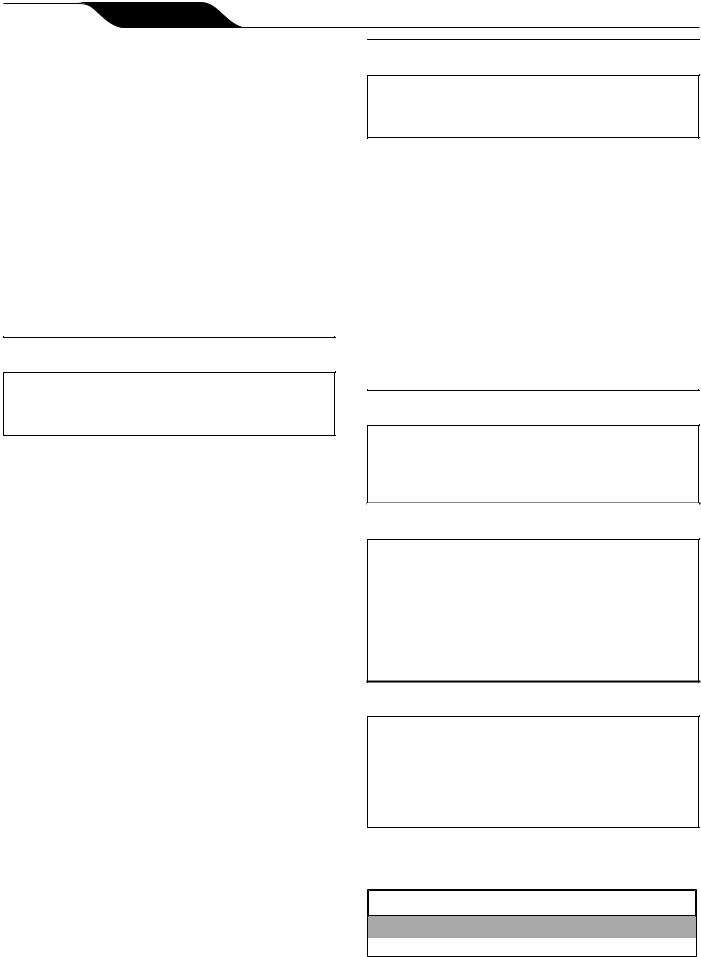
1.Use rigid PVC pipe with a minimum diameter of 3/4”, 1-1/2” is recommended, for the dedicated return line. Flexible PVC piping is not recommended for the dedicated pool return line underground as it can be damaged by expansion and movement caused by the surge of pump pressure. Refer to Figures 3 and 4.
From Filter or Heater |
|
|
|
Option #1 |
|
To Spa |
Horizontal |
|
Leg |
||
|
Street Ell |
|
Ground |
Polaris |
|
Level |
Reinforced |
|
Pool Return |
Hose |
|
To Booster |
||
|
||
|
Pump |
2.The booster pump inlet connection line should be at least 3/4” pipe. The Softube Quick Connect fittings are designed to work with the Polaris reinforced hose (part #P19) only
3.Do not tap into the top of a horizontal line.
4.Use 90° street ells to minimize bends and loops in the Polaris reinforced hose.
3.3.3 Pump Location
1.Zodiac Pool Systems, Inc. recommends installing the pump within one 1 foot (30 cm) above the water level. The pump should not be elevated more than a few feet above the water level of the pool.
2.If the pump is located below water level, isolation valves must be installed on both the suction and return lines to prevent back flow of pool water during any routine or required servicing.
 WARNING
Some Safety Vacuum Release System (SVRS) devices are not compatible with installation of check valves. If the pool has an SVRS device, be sure to confirm that it will continue to safely operate when any check valves are installed.
3.The pump and other circulation equipment must be located more than 5 feet (1,5 meter) from the water. Choose a location that will minimize turns in the piping.
NOTE In Canada, the pump must be located a minimum of 3.0 meters [approximately 10 feet] from the water (CSA C22.1).
4.The pump must be placed on a solid foundation that will not vibrate. To further reduce the possibility of vibration noise, bolt the pump to the foundation.
Figure 3. Preferred Plumbing Configuration |
NOTE Zodiac® recommends bolting the pump directly |
|
to the foundation. |
From Filter or Heater
Option #2
To Spa 

|
Option #3 |
Ground Level |
|
Pool Return |
Leave 6" |
|
5.The pump foundation must have adequate drainage to prevent the motor from getting wet. The pump needs to be protected from the rain and sun.
6.Proper ventilation is required for the pump to operate normally. All motors generate heat that must be removed by providing proper ventilation.
7.Provide access for future service by leaving a clear area around the pump. Allow plenty of space above the pump for servicing.
8.If the equipment is under cover, provide adequate lighting.
Figure 4. Alternate Plumbing Configuration

|
Polaris® PB4-60 Booster Pump | Installation and Operation Manual |
ENGLISH |
Page 9 |
||||
|
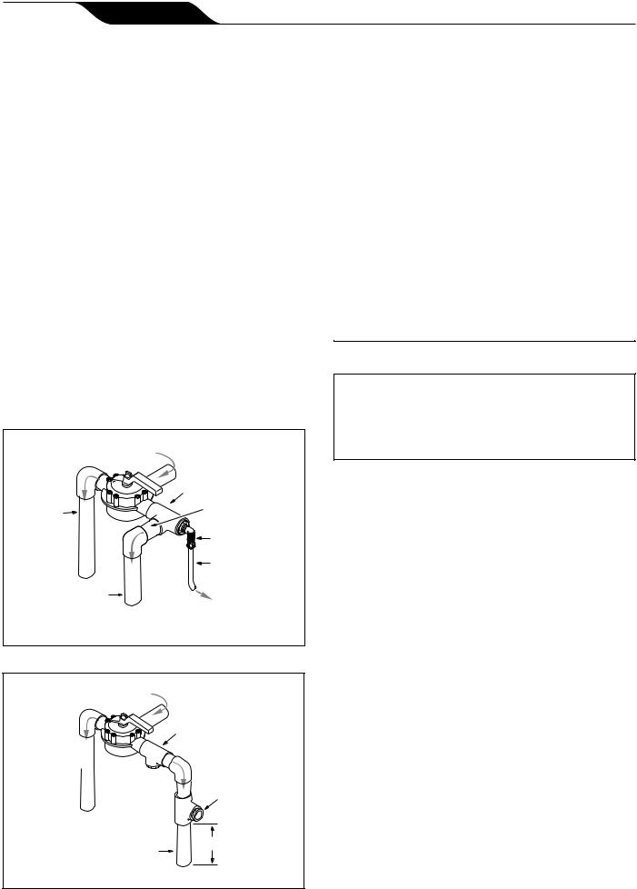
3.3.4 Install the Pump |
|
Connector Nut |
Nut Gap |
|
||
1. |
Mount the pump using two (2) concrete expansion |
|
|
||||
|
|
|
|
||||
|
|
|
|
|
|||
|
anchors to ensure stability. |
|
|
|
|
|
|
2. |
Apply four (4) to six (6) wraps of Teflon® tape |
|
|
|
|
|
|
|
to the tapered thread of the connecter barb. See |
|
|
|
|
|
|
|
Figure 5 (a). |
|
|
|
|
|
|
|
CAUTION |
|
Reinforced Hose |
Barb Face |
Connector Barb |
||
Pipe dope should NEVER be used on barb threads. |
|
|
|
|
|||
|
|
|
|
|
|||
Pipe dope will severely weaken the plastic, causing |
Figure 6. |
Tighten Connector Nut to Secure Hose |
|||||
leakage and may cause the plastic to fracture. DO |
|
routine or required servicing. |
|
||||
NOT OVERTIGHTEN. |
|
|
|||||
3. |
Thread and tighten the tapered thread of the |
2. |
To help prevent difficulty in priming, install the |
||||
|
suction pipe without high points (above inlet of |
||||||
|
connector barb into the pump port on the pump |
|
|||||
|
|
pump - inverted “U”s in plumbing), which can trap |
|||||
|
body. See Figure 5 (b). |
|
|||||
|
|
air. |
|
|
|
||
4. |
Trim reinforced hose to required length. Make sure |
|
|
|
|
||
3. |
The piping must be well supported and not forced |
||||||
|
cut is clean and square. Avoid unnecessary loops |
||||||
|
|
together where constant stress will be experienced. |
|||||
|
or bends in the hose. |
|
|||||
|
4. |
Always use properly sized valves. Jandy® Pro |
|||||
5. |
Slide connector nut onto the trimmed end of the |
||||||
|
Series diverter valves and ball valves typically |
||||||
|
hose with threaded end toward the cut end of the |
|
|||||
|
|
have the best flow capabilities. |
|
||||
|
hose. See Figure 5 (c). |
|
|
||||
|
5. |
Use the fewest fittings possible. Every additional |
|||||
6. |
Apply water to connector barb to help hose slide |
||||||
|
fitting has the effect of moving the equipment |
||||||
|
over barbs. Push trimmed edge of hose fully onto |
|
|||||
|
|
farther away from the water. |
|
||||
|
the connector barb. See Figure 5 (d). |
|
|
||||
|
NOTE If more than 10 suction fittings are needed, the |
||||||
7. |
Slide/Rotate the connector nut to the barb to |
||||||
|
pipe size must be increased. |
|
|||||
|
engage threads correctly, do not cross thread |
|
|
||||
|
|
|
|
|
|
||
|
connector nut. Tighten the connector nut until |
|
3.3.6 |
Check the Water Flow |
|
||
|
threads are no longer visible (gap about 1/8” or |
|
|
||||
|
NOTE This pump must have minimum outlet pressure |
||||||
|
just less than the width of two dimes), or until it |
||||||
|
touches the barb face. See Figure 6. |
|
of 45 psi. Lower pressure may cause an over- |
||||
|
3.3.5 Installation Recommendations |
|
current motor condition. |
|
|||
|
|
After the system is plumbed, verify water flow to |
|||||
1. If the pump is located below water level, isolation |
|
||||||
the booster pump by disconnecting the inlet supply line |
|||||||
|
valves must be installed on both sides of the pump |
at the booster pump and then turning on the filtration |
|||||
|
to prevent back flow of pool water during any |
pump. Water should flow from the line. |
|
||||
|
|
|
If there is no water flow, check the following: |
|
d |
|
|
Polaris |
|
|
a |
|
Reinforced |
|
|
Pump Body |
|
Hose |
|
|
|
|
|
|
|
Connector Nut |
b |
|
|
|
|
Inlet |
|
|
Connector Barb |
d |
|
|
|
|
|
|
Supply |
|
Reinforced Hose |
|
|
Line |
|
|
c |
Connector Barb |
|
Expansion |
|
|
1-1/2" Rigid |
||
|
|
|
Anchor |
|
|
|
|
PVC Pipe |
Dedicated return |
|
|
|
|
|
|
|
|
|
line to pool |
Figure 5. Prep and install Quick Connect barb and |
|
connector nut |
Figure 7. Complete Installation |

Page 10 |
ENGLISH |
Polaris® PB4-60 Booster Pump | Installation and Operation Manual |
1.Verify that the installation is correct. Refer to Figure 6.
2.Use smaller eyeball fittings in the pool return lines or plug a return line.
Once flow is established, the pump is ready for operation.
3.3.7 Conduct Pressure Test
 WARNING
When pressure testing a system with water, air is often trapped in the system during the filling
process. This air will compress when the system is pressurized. Should the system fail, this trapped air can propel debris at a high speed and cause injury. Every effort to remove trapped air must be taken, including opening the bleed valve on the filter and loosening the pump basket lid on the filter pump while filling the pump.
 WARNING
Trapped air in system can cause filter lid to be blown off, which can result in death, serious personal injury, or property damage. Be sure all air is properly out of system before operating. DO NOT USE COMPRESSED AIR TO PRESSURE TEST OR CHECK FOR LEAKS.
 WARNING
When pressure testing the system with water, it is very important to make sure that the pump basket lid on the filter pump is completely secure.
 WARNING
Do not pressure test above 35 PSI. Pressure testing must be done by a trained pool professional. Circulation equipment that is not tested properly can fail, which could result in severe injury or property damage.
1.Fill the system with water, using care to eliminate trapped air.
2.Pressurize the system with water to no more than 35 PSI.
3.Close the valve to trap pressurized water in the system.
4.Observe the system for leaks and/or pressure decay.
5.For technical support, contact Zodiac® technical support at 800.822.7933.
Section 4. Operation
4.1Start-up
CAUTION
Never run the booster pump without water. Running the pump “dry” for any length of time can cause severe damage to both the pump and motor and will void the warranty.
 CAUTION
Never run the booster pump without the cleaner connected. Running the pump without the cleaner connected will cause damage to the pump impeller and will void the warranty.
If this is a new pool installation, make sure all piping is clear of construction debris and has been properly pressure tested. The filter should be checked for proper installation, verifying all connections and clamps are secure according to the manufacturer's recommendations.
 WARNING
To avoid risk of damage or injury, verify that all power is turned off before starting this procedure.
1.Turn filtration pump ON.
2.Open the filter pressure release to relieve the system pressure until water comes out.
3.If the filter pump is located below the water level of the pool, opening the filter pressure release valve will prime the pump with water.
4.Once all the air has left the filter, close the pressure release valve.
5.Turn on the power to the booster pump. Then turn on the booster pump.
6.The booster pump should prime. The time it takes to prime will depend on the elevation and length of pipe used on the suction supply pipe. See Section 3.3.6 for proper elevation and pipe size.
7.If the booster pump does not prime and all the instructions to this point have been followed, check for a suction leak.
Polaris® PB4-60 Booster Pump | Installation and Operation Manual
Section 5. Maintenance
5.1Winterizing the Pump
 CAUTION
The pump must be protected when freezing temperatures are expected. Allowing the pump to freeze will cause severe damage and void the warranty.
 CAUTION
Do not use antifreeze solutions in the pool, spa, or hot tub systems! Antifreeze is highly toxic and may damage the circulation system. The only exception to this is Propylene Glycol. For more information see your local pool/spa supply store or contact a qualified swimming pool service company.
1.Drain all water from the pump, system equipment, and piping.
2.Remove the drain plug. Store the drain plug in a safe location and reinstall it when the cold weather season is over. Do not lose the o-ring. (Drain Plug with O-ring Set, R0537000).
3.Keep the motor covered and dry.
NOTE Covering the pump with plastic will create condensation, and this moisture will damage the pump. The best way to protect your pump is to have a qualified service technician or electrician properly disconnect the electrical wiring at the switch or junction box. Once the power is removed, the two (2) quick connect fittings can be loosened and the pump stored indoors. For safety, and to prevent entry of contaminants, reinstall all conduit and terminal box covers.
4.When the system is reopened for operation, make sure all piping, valves, wiring, and equipment are in accordance with the manufacturer's recommendations. Pay close attention to the filter and electrical connections.
5.The pump must be primed prior to starting; refer to Section 4.1, Start-up.
ENGLISH |
Page 11 |

Page 12 |
ENGLISH |
Polaris® PB4-60 Booster Pump | Installation and Operation Manual |
Section 6. Troubleshooting and Repair
Zodiac® strongly recommends that you call a licensed and qualified service professional in to perform any repairs on the filter/pump system. To locate an independent service company, check your local yellow pages or visit: www.zodiacpoolsystems.com.
6.1Troubleshooting
Symptom |
Possible Problem/Solution |
|
|
The cleaning/circulating system is |
Verify that skimmer baskets, pump basket and other screens are clean. Clean as |
not operating correctly. |
necessary. |
|
Check filter and clean as necessary. |
|
Check valve positions. Adjust as necessary. |
|
NOTE Multiple pieces of equipment operating at one time (for example, waterfalls, spa |
|
jets, and surface returns) may prevent the cleaning system from working properly. |
|
Check the cleaning system manually to ensure that the system is adjusted according to the |
|
manufacturer's recommendations. |
|
|
Bubbles present in the filtration |
Air in system. Check the pool or spa water level to ensure it is at the proper level and |
pump basket. |
that air is not being drawn into the suction piping. If the water is at normal level, turn off |
|
the pump. Remove the lid and check for debris around the lid o-ring seat or improper |
|
installation of the lid seal, as this either of these conditions will cause air to leak into the |
|
system. Clean the lid o-ring and place on the lid. Hand-tighten the lid to make an air tight |
|
seal. Do not use any tools to tighten the lid. Turn the pump back on. |
|
|
Air leaks are still present. |
Check the suction side piping union. While the pump is running, try to tighten the union. If |
|
this does not stop the air leak, turn off the pump. Loosen both unions and slide the pump |
|
out of the way. Remove, clean and re-install both union o-rings on the filtration pump. |
|
Reposition the pump next to the piping and secure the union nuts to the pump. With clean |
|
union o-rings, hand-tightening of the unions should create a seal. If the unions still do not |
|
seal, gently tighten with a large pair of tongue-and-groove pliers. |
|
Do not over-tighten. |
|
|
There is no air in the system, but |
It is possible that debris is caught in the pump impeller. The pump impeller moves the |
the pressure is still low. |
water, and the vanes in the impeller can become blocked with debris. See Section 6.2, |
|
Service Technician Maintenance, 6.2.1, Blocked Impeller, for more information. |
|
|
There is no debris blocking the |
The pump impeller is showing signs of normal wear. Have a qualified service technician |
impeller and the pressure is still |
check the impeller and replace as necessary. |
low. |
If the pump is part of a relatively new installation, it could be an electrical problem. Contact |
|
|
|
a qualified service technician. Have the technician check for loose electrical connections |
|
and check the voltage at the pump motor while it is in operation. The voltage must be within |
|
10% of the motor's data plate rating. If the voltage is not within 10%, contact a qualified |
|
electrician and/or the local power service provider. |
|
Pump seal is leaking air. Have a qualified service technician replace the seal. |
|
|
The pump is leaking water between |
This is caused by a damaged or failed mechanical seal. Replace the seal. See Section 6.2, |
the motor and pump body. |
Service Technician Maintenance, 6.2.4, Mechanical Seal Replacement. |
|
|
The pump gets hot and shuts off |
Ensure that there is adequate room around the motor to circulate air and keep the motor |
periodically. |
cool. Have a qualified electrician check for loose connections and check the voltage at the |
|
pump motor while it is in operation. The voltage must be within 10% of the motor's data |
|
plate rating. If the voltage is not within 10%, contact a qualified electrician and/or the local |
|
power service provider. |
|
|
 Loading...