


9400
H0363300 Rev -
OWNER’S MANUAL
English | Français | Español
 WARNING
FOR YOUR SAFETY - For anything other than the routine cleaning and maintenance described in this manual, this product must be serviced by a contractor who is licensed and qualified in pool equipment by the jurisdiction in which the product will be installed where such state or local requirements exist. In the event no such state or local requirement exists, the maintainer must be a professional with sufficient experience in pool equipment installation and maintenance so that all of the instructions in this manual can be followed exactly. Improper installation and/or operation will void the warranty.
 AVERTISSEMENT
POUR VOTRE SÉCURITÉ – Pour toute opération autre que l’entretien de routine et la maintenance décrite dans ce manuel, ce produit doit être pris en charge par une entreprise qui est autorisée et qualifiée pour la réparation des équipements de piscine par la juridiction où le dit produit est installé lorsque de telles exigences locales ou provinciales sont édictées. Si aucune exigence locale ou provinciale n’est disponible, l’agent d’entretien doit être un professionnel avec suffisamment d’expérience dans l’installation et la maintenance d’équipement de piscine pour appliquer correctement les consignes du présent manuel. L’installation ou l’utilisation inappropriée annulera la garantie.
 ADVERTENCIA
PARA SU SEGURIDAD - Para cualquier cosa con excepción de la limpieza rutinaria y mantenimiento de descritos en este manual, este producto debe ser atendido por un contratista que está autorizado y calificado en equipo de piscina bajo la jurisdicción en la que el producto se instala en donde requisitos de estado y locales existen. En el caso de que no exista ningún requisito de estado o local, el responsable debe ser un técnico profesional
con experiencia suficiente en la instalación de piscinas y mantenimiento de equipo para que todas las instrucciones en este manual puede ser seguidas exactamente. Inapropiada instalación y/o operación anulará la garantía.

Page 2
English
Table of Contents
Section 1. Important Safety Instructions ......... |
3 |
|
Section 2. |
Cleaner Specifications ................... |
5 |
2.1 |
General Specifications ................... |
5 |
Section 3. Assembly and Initial Usage............ |
5 |
|
3.1 |
Unpacking ...................................... |
5 |
3.2 |
Assembling the Transport Caddy ... |
5 |
3.3Connecting the Control Unit to the
|
Caddy............................................. |
7 |
3.4 |
Electrical Connection ..................... |
8 |
Section 4. |
Operation ....................................... |
8 |
4.1 |
Submerging the Cleaner ................ |
8 |
4.2 |
Operating the Cleaner.................... |
9 |
4.3 |
Remote Control Mode |
|
|
(9300xi Sport Only) ........................ |
11 |
4.4Enabling the Automatic Start Mode
(9300xi Sport Only) ........................ |
11 |
Section 5. Cleaning and Maintenance ............ |
12 |
|
5.1 |
Cleaning the Filter Canister............ |
12 |
5.2 |
Cleaning and Storing the |
|
|
Cleaner........................................... |
13 |
5.3 |
Replacing the Brushes ................... |
13 |
5.4 |
Replacing the Tires on the |
|
|
Cleaner........................................... |
14 |
Section 6. |
Replacement Parts ........................ |
15 |
Section 7. |
Troubleshooting ............................. |
16 |
7.1 |
General Troubleshooting................ |
16 |
THANK YOU FOR PURCHASING THE POLARIS CLEANER.
YOUR POLARIS CLEANER HAS BEEN DESIGNED AND MANUFACTURED TO BE EASILY INSTALLED AND TO PROVIDE LOW MAINTENANCE OPERATION. PRIOR TO INSTALLING YOUR NEW POLARIS CLEANER, PLEASE DO THE FOLLOWING:
1)Complete and return the warranty card.
2)Record your purchase information on the spaces provided below.
3)Attach your invoice (or a copy) to this page.
Taking these steps will help ensure prompt warranty service, should it be required. If service is required, please contact your original dealer. If the original dealer does not perform warranty service, please visit www.polarispool.com to locate an independent service company near you. If you are unable to locate a service company, please call our Technical Support department at 800-822-7933.
RECORD YOUR POLARIS CLEANER DATA HERE:
Date of Purchase |
Purchased From |
Serial Number: |
||||||||
|
|
|
|
|
|
|
|
|
|
|
|
|
|
|
|
|
|
(located on machine head) |
|||
City |
|
|
|
State |
|
Zip Code |
||||
|
|
|
|
|
|
|
|
|
|
|

Page 3
Section 1. Important Safety Instructions
Congratulations on purchasing the Polaris cleaner. Please take a moment to read through the entire manual before installing your new robotic pool cleaner. Your cleaner must be installed and operated as specified.
READ AND FOLLOW ALL INSTRUCTIONS
 WARNING
Failure to comply with the following warnings can result in permanent injury, electrocution or drowning.
PREVENT ELECTRICAL SHOCK
To reduce risk of electrical shock:
•Connect unit to receptacle protected by a ground fault circuit interrupter (GFCI). Such a GFCI receptacle should be provided by a qualified installer and should be tested on a routine basis. To test the GFCI, push the test button. The GFCI should interrupt power. Push the reset button. Power should be restored. If the GFCI fails to operate in this manner, the GFCI is defective. If the GFCI interrupts power to the pump without the test button being pushed, a ground current is flowing, indicating the possibility of an electric shock. Do not use this product. Disconnect the cleaner and have the problem corrected by a qualified service representative before using.
•Per the United States National Electric Code (NEC), keep the power unit at least five (5) ft. (1.5 m) from the edge of
the (pool/spa) water and do not remove it from its caddy. In Canada, the Canadian Electrical Code (CEC) requires a minimum distance of three (3) m (10 ft.) to be maintained between the pool edge and the power unit.
Never
submerge the control unit.
•Do not enter pool while the cleaner is in water.
•Do not bury cord. Locate cord so as to prevent it from being damaged by lawn mowers, hedge trimmers and other equipment.
•To reduce the risk of electrical shock, do not use the cleaner or control unit if the cord is worn or damaged. Contact Zodiac Pool Systems, Inc. immediately for a replacement cord.
•Double insulation—For continued protection against possible electric shock, use only identical replacement parts when servicing. Do not attempt repair of the cleaner, control unit, power cord, or floating cable.
•NEVER OPEN CONTROL UNIT.
•Do not use an extension cord to connect the unit to electric supply; provide a properly located outlet. The control unit should be placed near the outlet box.
PREVENT CHILD INJURY AND DROWNING
•To reduce the risk of injury, do not permit children to operate this product.
•Do not let anyone, especially small children, sit, step, lean, or climb on any equipment installed as part of your pool’s operational system.
English
Page 4
|
|
CAUTION |
|
|
Failure to comply with the following warnings could cause damage to pool equipment or personal |
|
|
injury. |
|
|
• This product is intended for use with permanently-installed pools. Do not use with storable pools. A |
|
|
|
|
|
permanently-installed pool is constructed in or on the ground or in a building such that it cannot be readily |
English |
|
disassembled for storage. A storable pool is constructed so that it is capable of being readily disassembled for |
|
• Turn the cleaner off before removing it from water, and do not operate out of water. |
|
|
|
storage and reassembled to its original integrity. |
|
|
• The cleaner must be installed and operated as specified. |
|
|
• Do not remove the cleaner from the pool for 15 minutes after the cleaning cycle has completed. |
|
|
• Clean filter canister in the cleaner after each use. |
|
|
|
|
|
• Do not use the product in your pool if the water temperature is above 95˚ F (35˚ C) or below 55˚ F (13˚ C). |
|
|
|
|
|
|
|
|
CAUTION |
|
|
USE OF THE POLARIS CLEANER IN A VINYL LINER POOL |
|
|
Certain vinyl liner patterns are particularly susceptible to rapid surface wear of pattern removal caused by objects |
|
|
coming into contact with the vinyl surface, including pool brushes, pool toys, floats, fountains, chlorine dispensers, |
|
|
and automatic pool cleaners. Some vinyl liner patterns can be seriously scratched or abraded simply by rubbing |
|
|
the surface with a pool brush. Ink from the pattern can also rub off during the installation process or when it comes |
|
|
into contact with objects in the pool. |
|
|
Zodiac Pool Systems, Inc., is not responsible for, and the Limited Warranty does not cover, pattern removal, |
|
|
abrasion or markings on vinyl liners. |
|
|
|
|
|
|
|
|
CAUTION |
|
|
POLARIS 9300xi SPORT ONLY |
|
|
This device complies with part 15 of the FCC Rules. Operation is subject to the following two (2) conditions: (1) this |
|
|
device may not cause harmful interference, and (2) this device must accept any interference received, including |
|
|
interference that may cause undesired operation. |
NOTE This equipment has been tested and found to comply with the limits for a Class B digital device, pursuant to part 15 of the FCC Rules. These limits are designed to provide reasonable protection against harmful interference in a residential installation. This equipment generates, uses and can radiate radio frequency energy and, if not installed and used in accordance with the instructions, may cause harmful interference to radio communications. However, there is no guarantee that interference will not occur in a particular installation. If this equipment does cause harmful interference to radio or television reception, which can be determined by turning the equipment off and on, the user is encouraged to try to correct the interference by one or more of the following measures:
•Reorient or relocate the receiving antenna.
•Increase the separation between the equipment and receiver.
•Connect the equipment to an electrical source on a circuit different from that to which the receiver is connected.
•Consult the dealer or an experienced radio/TV technician for help.
Modifications made to this equipment, which are not authorized by the manufacturer, may void the user’s authority to operate this equipment.
SAVE THESE INSTRUCTIONS
Section 2. Cleaner Specifications
2.1 General Specifications
The general specifications for the cleaner are as follows:
|
9300 Sport & |
9300xi Sport |
|
9400 Sport |
|
Control box |
100-125 VAC, 60 Hz |
100-125 VAC, 60 Hz |
supply voltage |
|
|
Supply voltage |
30 V DC |
30 V DC |
Installed load |
150 W max |
150 W max |
Cable length |
60 ft (21 m) |
70 ft (21 m) |
Cleaner size |
16.9 x 18.9 x 10.6 in. |
16.9 x 18.9 x 10.6 in. |
(WxDxH) |
43 x 48 x 27 cm |
43 x 48 x 27 cm |
|
|
|
Pack size |
22.8 x 22.8 x 23.2 in. |
22.8 x 22.8 x 23.2 in. |
(WxDxH) |
58 x 58 x 59 cm |
58 x 58 x 59 cm |
|
|
|
Weight of Cleaner |
25 lbs. (11.3 kg) |
25 lbs. (11.3 kg) |
Packed weight |
42 lbs. (19 kg) |
42 lbs. (19 kg) |
Filtration |
less than 100 |
less than 100 |
|
microns |
microns |
Cycle lengths |
1.30 hrs, 2.30 hrs. |
1.30 hrs, 2.30 hrs. |
The cleaner is a double-insulated product. A doubleinsulated electrical appliance is one which has been designed in such a way that it does not require a safety connection to ground. The basic requirement for doubleinsulation is that no single failure can result in dangerous voltage becoming exposed so that it might cause an electric shock and that this is achieved without relying on an earthed (grounded) metal casing. This is achieved by having two (2) layers of insulating material surrounding live parts or by using reinforced insulation. Therefore, devices having double-insulated construction, such as this cleaner, do not utilize a grounded (three-prong) cord/plug.
Section 3. Assembly and Initial
Usage
3.1 Unpacking
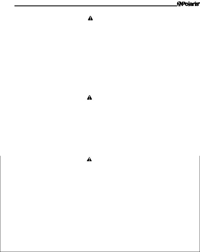
The packaging should contain the following items (Refer to Figure 1):
•Polaris cleaner
•Control unit
•Remote control (9300xi Sport only)
•Transport and storage caddy (complete with assembly components)
Page 5
|
|
X1 |
|
|
|
|
X4 |
|
|
|
|
X4 |
|
X1 |
|
|
|
|
|
|
|
English |
|
X4 |
X2 |
|
|
|
|
|
|
|
|
||
X2 |
|
|
X4 |
|
|
|
|
|
|
||
|
|
X1 |
|
X1 |
|
|
X1 |
X1 |
|
|
|
|
|
|
|
|
Figure 1. Components
Check that the unit has not been damaged during transport. If you detect damage, contact Zodiac Pool Systems, Inc. at 1-800-822-7933 before using your cleaner.
To unpack the cleaner and its components:
1.Remove the lower portion of the caddy along with the upper and lower power cable hooks, control unit hook, power cable hook plate, locking plate, nuts, bolts and screws.
2 Remove the small box that contains the control unit.
3.Remove the handles (left and right) of the caddy, which are located against one side of the box.
4.Remove the cleaner from the box.
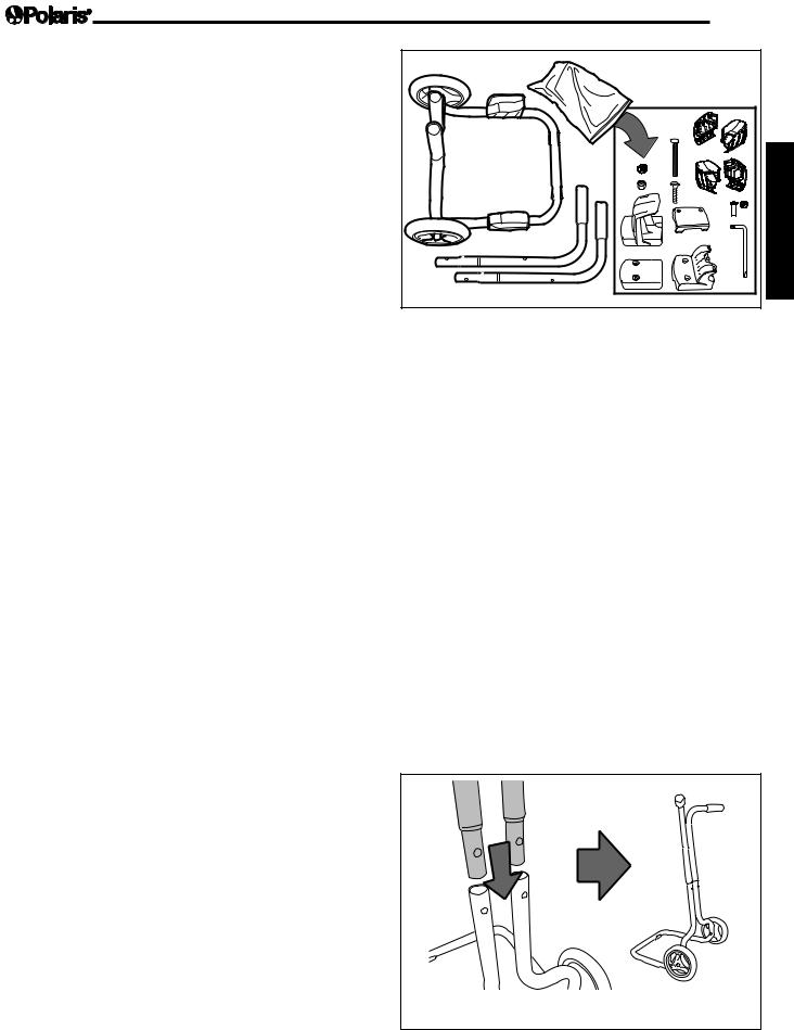
3.2 Assembling the Transport Caddy
1.Insert the upper tubes (handles) into the bottom tubes on the cart as shown in Figure 2. Make sure the upper tubes (handles) are in the proper orientation and align the screw holes.
1
Figure 2. Install the Handles
Page 6
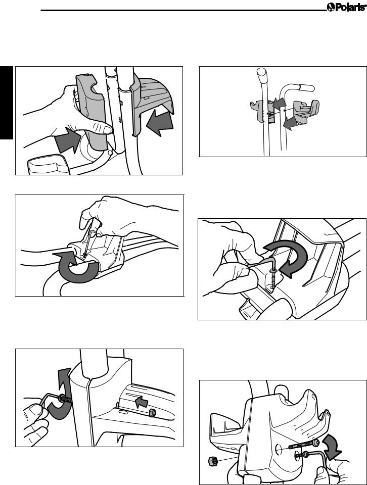
2.Position the bottom power cable hook as shown in Figure 3. Place the cable hook plate opposite the power cable hook. Secure using a screw and
tightening with the Torx® wrench. Refer to Figure 4.
4.Position the power cable hook and control unit hook on the upper tubes as shown in Figure 6. Make sure the upper tubes (handles) are in the proper orientation.
English |
2 |
|
3
Figure 3. Position the Bottom Power Cable Hook
4
Figure 4. Secure the Bottom Power Cable Hook
3.Secure the cable hook plate using two (2) bolts and two (2) nuts and tighten with Torx wrench. Refer to Figure 5.
5
6
7
Figure 6. Position the Bottom Power Cable Hook
5.Secure the power cable hook and control unit hook around the tubes using a screw and hand tighten with the Torx wrench (supplied with unit). Refer to Figure 7.
8 |
Figure 7. Install the Power Cable Hook and Control Unit Hook
6.Secure the control unit hook using two (2) bolts and two (2) nuts and tighten with Torx wrench. Refer to Figure 8.
Figure 5. Secure the Cable Hook Plate |
9 |
Figure 8. Secure the Hooks
Page 7
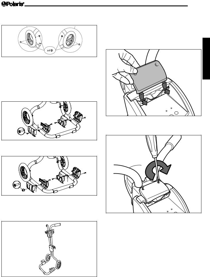
7.Place two (2) caps on the wheels as shown in figure 9.
Figure 9. Attaching Wheel Caps
8.Attach the support blocks to the caddy using four
(4) screws as shown in Figures 10 and 11.
For the Polaris 9300 Sport and 9300xi Sport, see Figure 10 for orientation and positioning of the blocks.
For the Polaris 9400 Sport, see Figure 11 for the correct orientation and postioning of the blocks.
3.3Connecting the Control Unit to the Caddy
1.Position the control unit over the control unit hook on the caddy.
2.Slide the locking plate clips into the control hook and line up the screw holes. Refer to Figure 13.
1 
English
x4 
Figure 10. Attaching the Support Blocks (Polaris 9300 Sport & 9300xi Sport)
x4 |
Figure 11. Attaching the Support Blocks
(Polaris 9400 Sport)
9.The transport caddy is now ready to use as shown in Figure 12.
Figure 13. Position the Locking Plate Clips
3.Secure the locking plate using Phillips head screws. Do not overtighten. Refer to Figure 14.
 2
2
Figure 14. Secure the Locking Plate
Figure 12. Transport and Storage Caddy Assembled
Page 8
3.4 Electrical Connection
 WARNING
Failure to comply with the following warnings can result in permanent injury, electrocution or drowning.
|
|
PREVENT ELECTRICAL SHOCK |
English |
• |
AMERICAS: Per NEC requirements, keep the |
|
control unit at least five (5) ft. (1.5 m) from the edge |
|
|
|
|
|
|
of the pool. CANADA: Per CEC requirements, keep |
|
|
the control unit at least three (3) m (10 ft.) from the |
|
|
edge of the pool. |
|
• Only connect the control unit to a receptacle |
|
|
|
protected by a ground fault circuit interrupter (GFCI). |
|
|
Contact a certified electrician if you cannot verify |
|
|
that the receptacle is protected by a GFCI. |
|
• |
Do not use an extension cord to connect the control |
|
|
unit. |
|
• |
Do not allow anyone to swim while the cleaner is in |
|
|
the pool. |
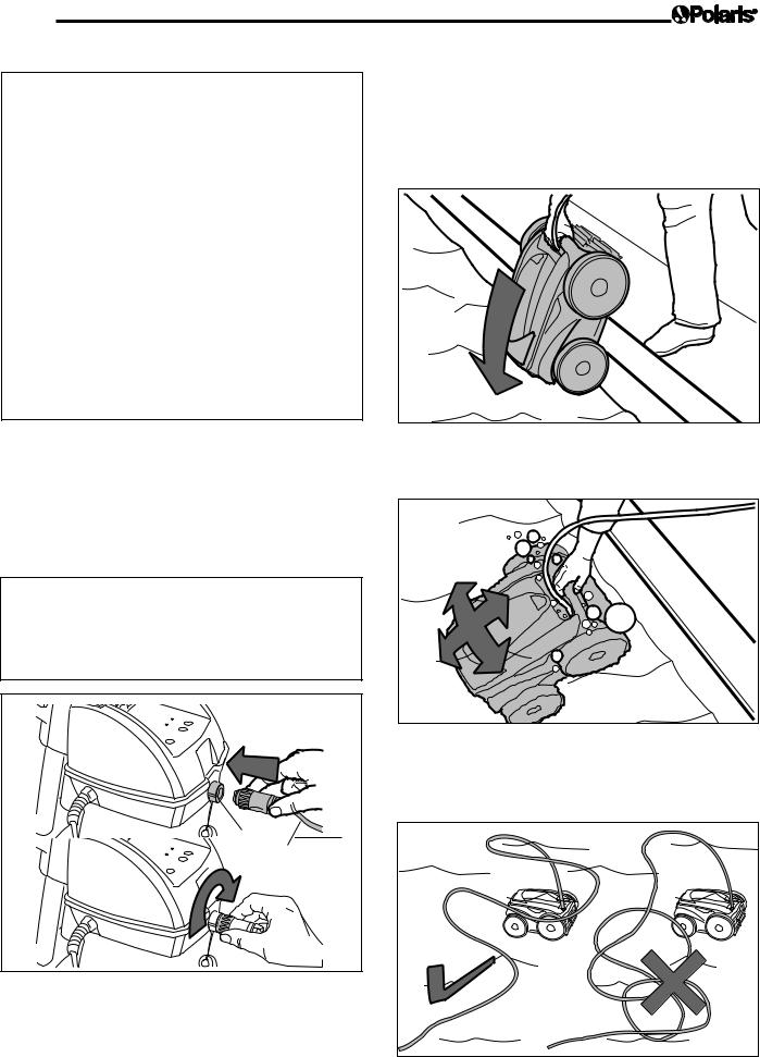
For your safety and to obtain the best possible performance from your cleaner, connect the cleaner’s floating cable to the control unit and thread connector until it is snug. Do not overtighten. Refer to Figure 15.
•The control unit is equipped with an automatic shut off feature to prevent overheating if operated in direct sunlight for an extended period of time.
 WARNING
The control unit is water-resistant, not waterproof. In order to prevent electrocution, which could result in serious injury or death, never submerge the control
unit.
 Power Supply
1
Connector
Floating Cable
 2
2
Figure 15. Electrical Connection
Section 4. Operation
4.1 Submerging the Cleaner
1.Submerge the cleaner in the pool and remove any air trapped inside by keeping the unit vertical. Refer to Figure 16.
1 |
Figure 16. Submerge the Cleaner Vertically |
2.Ensure the unit sinks to the bottom of the pool. Refer to Figure 17.
2
Figure 17. Cleaner on the Bottom of the Pool
3.Spread out the floating cable over the pool, ensuring there are no kinks or coils in the cable. Refer to Figure 18.
Figure 18. Spread Floating Cable Over the Pool
4.2 Operating the Cleaner
9300 Sport and 9400 Sport
Select either the Cycle I or Cycle II cleaning program on the control unit:
|
Cycle I Program |
|
Cycle II Program |
• |
Completed in 1.5 hours |
• |
Completed in 2.5 hours |
• |
Maximum coverage in |
• |
Intensive and complete |
|
minimal time |
|
cleaning |
|
|
• |
Thorough tile cleaning |
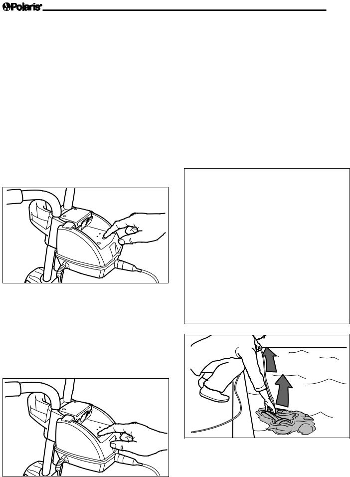
1.To start your cleaner, press the button for "Cycle I" cleaning program. "Cycle I" cleaning is the primary cleaning cycle for inground pools. If an alternative cycle is preferred, press "Cycle II". Refer to Figure 19. The indicator light illuminates and the cleaner starts up after just a few seconds. When the cleaner is powered ON it will remain in standby until the Cycle I button is pressed.
Figure 19. Start the Cleaner
2.When the "Cycle I" program button is selected the indicator light above will illuminate. The cleaner will start in a few seconds.
3.To change the selected cleaning cycle, press the new cycle button and the new cycle will start in a few seconds.
4.If you wish to stop the cleaner during a cleaning cycle, press the OFF button. Refer to Figure 20.
|
Page 9 |
|
5. |
At the end of the cycle, the cleaner will stop and |
|
|
after 15 minutes the light will flash slowly to |
|
|
indicate the cycle is completed. |
|
6. |
The cleaner includes a safety feature that |
|
|
automatically stops the cleaner after about 20 |
|
|
seconds, when it is powered on, but not submerged |
|
|
|
|
|
in the water. For pools equipped with a beach area, |
|
|
this safety feature allows the cleaner to reverse, |
English |
|
and back into the pool when the impeller is out of |
|
|
the water. |
|
7. |
Disconnect the control unit cable from the |
|
|
electrical outlet. |
|
8. |
Disconnect the cable from the control unit. |
|
9. |
At the end of each cycle, coil the cable starting |
|
|
||
|
at the cleaner and go toward the connection |
|
|
point at control unit. Remove coils or twists |
|
|
along the way. |
|
 CAUTION
To prevent damage to the cleaner, be sure to adhere to the following guidelines:
•Approximately 15 minutes after the cycle is completed, the light located on the control unit will flash slowly to indicate that the cleaner may be removed from the pool. The 15 minute period allows the motor to cool and will prevent damage to the cleaner.
•Remove the cleaner from the pool after the cleaning cycle is completed and store on the caddy.
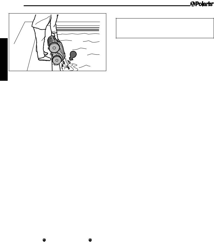
•Never lift the cleaner out of the pool by the floating cable. Always use the handle to remove it from the pool. Refer to Figures 21 and 22.
•Remove the cleaner from pool when super chlorinating.
•Do not handle cleaner while it is in operation.
1
2
Figure 21. Remove Cleaner From Pool
Figure 20. Turn Cleaner Off
Page 10
English |
3 |
|
Figure 22. Keep Cleaner Vertical to Drain Water
IMPORTANT
•Use your cleaner as often as needed to keep your pool clean.
•Clean the filter canister after each cleaning cycle.
•Do not leave your cleaner in the pool on a permanent basis.
•At the end of each cycle, remove the cleaner from the pool. Start at the cleaner head and untangle any coils in the hose before storing the cleaner.
9300xi Sport
1.Plug the control unit into a GFCI protected power source.
Select either the Cycle I or Cycle II cleaning program on the control unit:
|
Cycle I Program |
|
Cycle II Program |
• |
Completed in 1.5 hours |
• |
Completed in 2.5 hours |
• |
Maximum coverage in |
• |
Intensive and complete |
|
minimal time |
|
cleaning |
|
|
• |
Thorough tile cleaning |
2.To start your 9300xi Sport cleaner, press the button for "Cycle I" cleaning program. "Cycle I" cleaning is the primary cleaning cycle for inground pools.
3.When the "Cycle I" program button is selected the indicator light above will illuminate. The cleaner will start in a few seconds.
4.Depending on the state of your pool it is possible to modify the time of the cleaning cycle by
pressing the  button. Pressing the
  button
will increase the cleaning time by 60 minutes or decrease the cleaning time by 30 minutes. When the cleaner is powered on, the Cycle and time will correspond to the cycle and the time that were active at the time it was last switched off.
5.If you wish to stop the cleaner during a cleaning cycle, press the "Power" button. Refer to Figure 20.
Removing the 9300xi Sport
 CAUTION
To prevent damage to the 9300xi Sport, be sure to adhere to the following guidelines:
1.After the cleaning cycle is completed, the four (4) lights located on the control unit will flash slowly to indicate that the cleaner may be removed from the pool.
2.Disconnect the control unit cable from the electrical outlet.
3.Disconnect the cable from the control unit.
4.Never lift the 9300xi Sport out of the pool by the floating cable. Always use the handle to remove it from the pool. Refer to Figures 21 and 22.
5.Coil the cable starting at the cleaner and go toward the connection point at control unit. Remove coils or twists along the way.
6.Store the Polaris 9300xi Sport on the caddy with the cable coiled when not in use.
IMPORTANT NOTES
•The 9300xi Sport includes a safety feature that automatically stops the cleaner after 20 seconds, if it is powered on, but not submerged in the water. For pools equipped with a beach area, this safety feature allows the cleaner to reverse, and back into the pool when the impeller is out of the water.
•Use your 9300xi Sport cleaner as often as needed to keep your pool clean.
•Clean the filter canister after each cleaning cycle.
•Do not leave your cleaner in the pool on a permanent basis.
•At the end of each cycle, remove the cleaner from the pool. Start at the cleaner head and untangle any coils in the hose before storing the cleaner.
•Remove the 9300xi Sport from pool when super chlorinating.
|
|
|
|
|
|
Page 11 |
|
|
|
|
|
|
|
||
4.3 |
Remote Control Mode |
To turn the cleaner, you must hold down the rotate left |
|||||
|
|
(9300xi Sport Only) |
or rotate right button. |
|
|
||
|
|
|
|
When using the remote control unit, the two (2) lights on |
|||
|
|
|
CAUTION |
||||
|
This device complies with part 15 of the FCC Rules. |
|
|
|
|
||
|
Operation is subject to the following two (2) conditions: |
the control unit |
will flash alternately. |
||||
|
(1) this device may not cause harmful interference, and |
|
|
|
|
||
|
(2) this device must accept any interference received, |
To return to automatic mode, either stop using the re- |
|||||
|
including interference that may cause undesired opera- |
mote control unit buttons for a minimum of 45 seconds |
|||||
|
tion. |
|
|
or press Cycle I or Cycle II button on the control unit. |
|||
|
NOTE This equipment has been tested and found to |
|
|
|
|
||
|
comply with the limits for a Class B digital device, pursuant |
4.4 Enabling the Automatic Start Mode |
|||||
|
to part 15 of the FCC Rules. These limits are designed to |
||||||
|
|
(9300xi Sport Only) |
|
|
|||
|
provide reasonable protection against harmful interference |
|
|
|
|||
|
in a residential installation. This equipment generates, uses |
This Automatic Start Mode allows the control unit to |
|||||
|
and can radiate radio frequency energy and, if not installed |
launch a pre-selected cleaning cycle triggered by an |
|||||
|
and used in accordance with the instructions, may cause |
external source (timer / programming clock). |
|||||
|
harmful interference to radio communications. However, |
The cycle can be either "Cycle I" or "Cycle II”. |
|||||
|
there is no guarantee that interference will not occur in a |
||||||
|
The 9300xi Sport will run for 2.5 hours. |
||||||
|
particular installation. If this equipment does cause harmful |
||||||
|
It is not possible to change the running time when |
||||||
|
interference to radio or television reception, which can be |
||||||
|
operating in this mode. |
|
|
||||
|
determined by turning the equipment off and on, the user |
|
|
||||
|
|
|
|
|
|||
|
is encouraged to try to correct the interference by one or |
Procedure for launching a cycle with |
|||||
|
more of the following measures: |
||||||
|
• |
Reorient or relocate the receiving antenna. |
a programming clock (timer): |
||||
|
• |
Increase the separation between the equipment |
1. |
Connect the control unit to the power supply outlet. |
|||
|
|
and receiver. |
|||||
|
|
2. |
To automatically start the |
“Cycle I”, press the |
|||
|
• |
Connect the equipment to an electrical source on |
|||||
|
|
a circuit different from that to which the receiver is |
|
following button for more than three (3) seconds: |
|||
|
|
connected. |
|
|
|
|
|
|
• |
Consult the dealer or an experienced radio/TV |
|
+ Cycle I |
|
|
|
|
|
technician for help. |
3. |
To automatically start the "Cycle II”, press the |
|||
|
Modifications made to this equipment, which are not |
||||||
|
|
following button for more than three (3) seconds: |
|||||
|
authorized by the manufacturer, may void the user’s |
|
|
|
|
||
|
authority to operate this equipment. |
|
+ Cycle II |
|
|
||
|
|
|
|
|
|
|
|
|
Remote control of the Polaris 9300xi Sport is available |
4. |
The two (2) lights will flash once |
||||
|
5. |
The robot will start automatically when it is |
|||||
|
using the hand held remote control unit. |
||||||
|
|
powered on. |
|
|
|||
|
The remote control unit has four (4) buttons: |
|
|
|
|||
|
Procedure for cancelling an automatic start: |
||||||
|
|
|
|
||||
|
|
|
Rotate Right |
1. Connect the control unit to the receptacle. |
|||
|
|
|
Reverse |
2. |
Press the OFF button for more than six (6) seconds. |
||
|
|
|
|
|
|
|
|
|
|
|
|
3. |
The two (2) lights will flash once |
||
|
Rotate Left |
|
|
|
|
||
|
|
Forward |
|
|
|
|
|
|
|
|
|
|
|
|
|
Figure 23. Remote Control
English
Page 12
Section 5. Cleaning and Maintenance
 WARNING
To avoid electric shock and other hazards which could result in permanent injury or death, disconnect (unplug) the cleaner from the power source before performing any cleaning and maintenance.
English |
5.1 Cleaning the Filter Canister |
|
|
||
|
The filter canister should be cleaned at the end of each |
|
|
cycle. |
|
|
1. |
Ensure that the control unit cable has been |
|
|
disconnected from the electrical outlet or that the |
|
|
floating cable has been disconnected from the |
|
|
control unit. |
|
2. |
Remove the cleaner from the water and let the |
|
|
remaining water drain by maintaining the cleaner |
|
|
in the vertical position. |
|
3. |
Set the unit on its wheels. |
|
4. |
To remove the filter from the cleaner, follow the |
|
|
steps 1 through 6 (Figures 24 through 27). |
|
5. |
Push the cover lock (1) and lift the cover (2) until |
|
|
it is secured in the vertical position. Refer to |
|
|
Figure 24. |
|
|
1 |
|
|
2 |
Figure 24. Lift Cleaner Cover
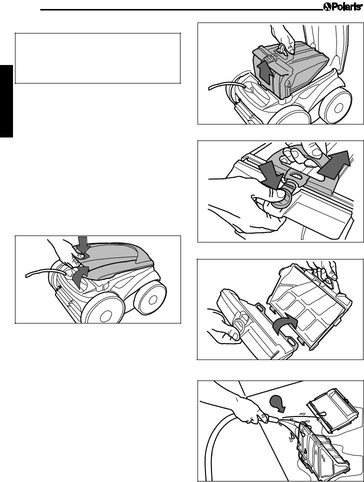
6.Remove the filter assembly from the body (3), as shown in Figure 25.
7.Push the quick release button on the canister assembly (4) and pull open the filter assembly (5). Refer to Figure 26.
8.Separate the filter canister from the filter support (6), as shown in Figure 27.
9.Wash the filter canister, the filter support, and the cleaner under water or using a hose (7). Refer to Figure 28.

 3
3


Figure 25. Remove Filter Assembly
4 |
5 |
|
Figure 26. Open Filter Assembly
6 |
Figure 27. Remove Filter Canister
7
Figure 28. Wash Filter Canister
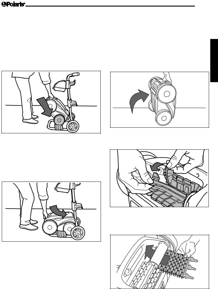
5.2 Cleaning and Storing the Cleaner
The cleaner must be cleaned regularly using slightly soapy clean water, do not use solvents such a trichloroethylene or its equivalent. Rinse the cleaner generously using clean water. Do not let your cleaner dry in direct sunlight near the pool. The cleaner must be stored on its own caddy, so that it dries quickly.
1.Place the rear wheels on the caddy side wedges as shown in Figure 29.
1 |
Figure 29. Position Cleaner on Caddy
2.Roll the unit into place onto the caddy. Refer to Figure 30.
NOTE The cleaner cable must be disconnected from the control box before removing the cleaner from the pool. Wrap the cleaner cable around the hooks located at the rear of the caddy.
2
Page 13
5.3 |
Replacing the Brushes |
|
The cleaner is fitted with PVC brushes. There are ''wear'' |
|
|
indicators on the brushes. To maintain cleaner perfor- |
|
|
mance at its best you need to replace the brushes as soon |
|
|
as one of the wear indicators has been reached (even if |
|
|
the blade wear is not even). Zodiac Pool Systems, Inc. |
|
|
recommends that you replace the brushes every two (2) |
English |
|
|
handle is up. Refer to Figure 31. |
|
years. |
|
|
1. |
Lift the cleaner to a vertical position so that the |
|
1 |
Figure 31. Clean in Upright Position
2.Separate the edges of the brush and undo the tabs as shown is Figure 32. Remove the worn brushes.

 2
2
Figure 32. Undo the Tabs of the Brush
3.To install a new brush, position the new brush on the roller with the spikes facing downwards. Refer to Figure 33.
Figure 30. Roll Cleaner onto Place on the Caddy
3
Figure 33. Install the New Brush

Page 14
4.Thread each tab into the slot provided and gently feed it through until the heel comes out at the other side of the slot. Refer to Figure 34.
5.4 Replacing the Tires on the Cleaner
1.Pull on the inside of the old tire to remove the tire lip from the wheel. See Figure 36.
4
English
Figure 34. Pull Tabs Through Each Slot
5.Use a pair of scissors to cut the tabs 3/4 inch from the heel so that they are no higher than the spikes as shown in Figure 35.
6.Repeat this procedure to install the second brush.

 1
1


Figure 36. Pull the Old Tire Over the Wheel
2.Remove the old tire as shown in Figure 37.
2
Figure 37. Remove the Old Tire
3. To replace the tire, position the tire on the wheel
Figure 35. Cut Tabs |
making sure to orient the tire so that the tread is on |
|
the outer side of the wheel. See Figure 38. |
||
|
||
|
IMPORTANT NOTE The word "inside" is imprinted on |
|
|
the rim of the tire. Make sure the |
|
|
word "inside" is facing towards the |
|
|
body of the cleaner. |
E
ID
S
N
I
I N S I D E
Towards
Body
I
N
S
I
D
E
1
Figure 38. Tire Replacement Orientation

|
Page 15 |
4. Push one side of the tire on to the wheel and fit the |
Section 6. Replacement Parts |
rib of the tire in the groove of the wheel as shown |
The complete replacement parts list and exploded |
in Figure 39. |
|
|
view is available on the Polaris website at |
|
www.polarispool.com. |
2
English
Figure 39. Start on One Side of the Tire
5.Work the tire onto the wheel and verify the rib of the tire is positioned properly within the groove of the wheel. Refer to Figure 40.
3
Figure 40. Work the Tire On Around the Wheel
6.Push and position the rib of the inner side of the tire in the groove of the wheel. Refer to Figure 41. If needed, turn the wheel gently to help with installation.
4
Figure 41. Push the Tire into Place on the Wheel

Page 16
Section 7. Troubleshooting
English
7.1 General Troubleshooting
Table 1 lists some of the more common symptoms, causes and solutions encountered when using the cleaner. The unit employs flashing lights during Cycle I and II to indicate different issues on the control unit and on the cleaner. These indications are not necessarily major issues. To turn off the flashing light, press the power button. Then start a new cycle: If the flashing lights persist after completing troubleshooting, please contact your retailer. DO NOT open the control unit.
Symptom |
Cause |
Solution |
|
The flashing indicator |
Ensure the floating cable is properly |
Unplug the floating cable from the control unit and |
|
lights appear just after |
plugged into the control unit. |
plug it again properly. |
|
start (pressing the Power |
|
|
|
Ensure the cleaner is well sub- |
Submerge the cleaner following the procedure in |
||
or Cycle button to start the |
|||
merged. |
Section 4.1, "Submerging the Cleaner". |
||
cleaner) (< 20 seconds). |
|||
Cleaner needs to be reset and start |
Press the power button OFF and then Cycle I or II |
||
|
|||
|
new cycle. |
Program buttons to start new cycle. |
|
|
Propeller does not turn. |
Please contact your local Polaris service represen- |
|
|
|
tative. |
|
|
Wheels do not turn. |
Please contact your local Polaris service represen- |
|
|
|
tative. |
|
The flashing lights appears |
If the cleaner sucks air for 60 sec- |
Submerge the cleaner following the procedure in |
|
during the cycle. |
onds, the flashing light appears. |
Section 4.1, "Submerging the Cleaner". |
|
The cleaner does not stay |
There is air in the appliance casing. |
Submerge the cleaner following the procedure in |
|
firmly on the pool bottom. |
|
Section 4.1, "Submerging the Cleaner". |
|
The cleaner does not or no |
The filter is full or dirty. |
Clean the filter canister following the procedure |
|
longer climbs the pool sides. |
|
Section 5.1, "Cleaning the Filter Canister". |
|
|
Sides of pool are slippery or slimy. |
Do a shock chlorination treatment and slightly re- |
|
|
Although the water seems clear, |
duce the pH. DO NOT leave the cleaner in the pool |
|
|
microscopic algae, invisible to the |
during this treatment. |
|
|
human eye, are present in the pool. |
|
|
|
As a result the pool sides become |
|
|
|
slippery and prevent the cleaner from |
|
|
|
climbing. |
|
|
On startup the cleaner does |
Not supplied with electricity. |
The outlet, the control unit is connected to, is not |
|
not move. |
|
supplying electrical power. Check that the outlet |
|
|
|
to which the control unit is connected is receiving |
|
|
|
electricity. |
|
|
Unit is turned ON. |
Check that you have started one (1) of the two (2) |
|
|
|
programs and check that the indicator for the se- |
|
|
|
lected program is lit. If the problem persists, contact |
|
|
|
your local Polaris service representative. |
|
The cycle I and II program |
Your cleaner has encountered a |
Disconnect the control unit and wait 20 seconds |
|
indicators flash alternately. |
problem or a issue during its opera- |
before reconnecting the control unit. Check that |
|
|
tion. |
the cable is correctly connected to the control unit. |
|
|
|
Check that no debris impedes the rotation of the |
|
|
|
brushes and/or the propeller. Clean the filter. Start |
|
|
|
a new cleaning program. If the problem continues |
|
|
|
contact your local Polaris service representative. |
|
|
|
|
|
The cleaner seems to be |
The brushes have become smooth. |
Replace the brushes following the procedure in |
|
performing less efficiently. |
|
Section 5.3, "Replacing the Brushes". |
|
|
Filter canister is full or dirty. |
Clean the filter canister following the procedure in |
|
|
|
Section 5.1, "Cleaning the Filter Canister". |
|
|
Floating cable is excessively coiled or |
Make sure the floating cable is spread out over the |
|
|
kinked. |
pool. |
 Loading...