

Page 1
F731 Universal Feeder
F734/F735 High Capacity Loader
Operator Guide
English Version
Page 2

Page 3

Table of Contents
Chapter 1—Introduction
Important Safety Notes ............................................................... 1-2
A Note to the Operator ................................................................ 1-4
About Your System .....................................................................1-4
The F731 Universal Feeder .................................................. 1-4
The F734/F735 High Capacity Loader .................................. 1-5
System Components - F734/F735 .............................................. 1-6
System Components - F731 ....................................................... 1-8
Operator Controls - F734/F735 ................................................. 1-10
Operator Controls - F731 .......................................................... 1-12
Chapter 2—Operation
F731 Universal Feeder Setup ..................................................... 2-2
Accumulator Input Frame Position ........................................ 2-2
Accumulator Ramp Height .................................................... 2-2
Power Up .............................................................................. 2-3
Select the Program ............................................................... 2-4
Loading Orientation .............................................................. 2-5
Feeder Side Guides Adjustment ........................................... 2-5
Set the Scanning Head ......................................................... 2-6
Side to Side Adjustment of OMR Scanners .......................... 2-6
Side to Side Adjustment of BCR Scanners ........................... 2-8
Setting the Material Guide Fingers ..................................... 2-10
Feeder Head Adjustment for cut sheets and booklets
up to 2.5mm (3/32") thick .................................................... 2-11
Feeder Head Adjustment for booklets 2.5mm (3/32") thick
or greater ............................................................................ 2-11
iSDC790A
Page 4

Table of Contents
Chapter 2—Operation (continued)
F734/F735 High Capacity Loader Setup ..................................2-14
Set the DI900/DI950 System .................................................... 2-16
Running the System .................................................................2-17
Chapter 3—Programming
About Programming Jobs ........................................................... 3-2
Adding a Non-Scanning Program ............................................... 3-2
Adding a Scanning Program ....................................................... 3-5
Deleting a Program ................................................................... 3-13
Modifying a Program ................................................................. 3-14
Transport Material to Accumulator ...................................... 2-12
Setting the Accumulator Side Guides ................................. 2-12
Accumulator Ramp Adjustment .......................................... 2-12
Deactivate Inline Test? ........................................................ 2-13
Load Paper ......................................................................... 2-13
Programming an 'OMR DI900/DI950' Job ............................ 3-5
Programming a 'BCR Standard' Job ................................... 3-11
Chapter 4—Troubleshooting and Maintenance
The User's Menu ........................................................................ 4-2
Options Available .................................................................. 4-2
Handling Material Stoppages ...................................................... 4-3
Stoppages in the F731 Universal Feeder ............................. 4-3
Stoppages in the F734/F735 High Capacity Loader ............. 4-4
Troubleshooting Charts ..............................................................4-5
Troubleshooting Using the F731 Scan Error Screens ................ 4-7
Operator Maintenance ................................................................ 4-8
Chapter 5—Reference
Service ........................................................................................ 5-2
Compliance ................................................................................ 5-2
Equipment Specications ...........................................................5-3
Material Specications ................................................................ 5-4
Index
Index .................................................................................... Index-1
ii SDC790A
Page 5
Contact Information
USA Contacts
Product Name - F731 (Universal Feeder) or F734 (High Capacity Loader)
▪ For frequently asked questions, go to:
Support.
▪ To place requests for service or training, go to:
Account.
▪ To order supplies and accessories, call the Supply Line™ at: 1.800.243.7824 or
go to: www.pb.com and click on Online Store.
▪ To view and pay invoices online, go to:
▪ To view inventory, go to:
▪ For direct questions, call: 1.800.522.0020. Customer Service Representatives
are available Monday through Friday, 8:00 AM - 8:00 PM ET.
www.pb.com and click on My Account.
www.pb.com and click on Customer
www.pb.com and click on My
www.pb.com and click on My Account.
Canada Contacts
Product Name - F731 (Universal Feeder) or F734 (High Capacity Loader)
▪ For frequently asked questions or to order supplies, go to: www.pitneybowes.ca
▪ For direct questions, call: 1.800.672.6937. Customer Service Representatives
are available Monday through Friday, 8:30 AM - 4:00 PM ET.
Other Country Contacts
• If you require help or wish to purchase supplies for your system, contact your
machine supplier.
• Contact information for all European Pitney Bowes companies is given in a
separate publication supplied with your system.
• If your system has been provided by a dealer or company outside the European
area, contact details will be on the rear cover of this guide, or on a label fixed to
the machine.
iiiSDC790A
Page 6

Table of Contents
iv SDC790A
Page 7
1 • Introduction
This chapter lists the key features of your system, and presents
important safety information.
Important Safety Notes ................................................................1-2
A Note to the Operator.................................................................1-4
About Your System ......................................................................1-4
The F731 Universal Feeder ................................................... 1-4
The F734/F735 High Capacity Loader .................................. 1-5
System Components - F734/F735...............................................1-6
System Components - F731 ........................................................1-8
Operator Controls - F734/F735 .................................................1-10
Operator Controls - F731...........................................................1-12
1-1SDC790A
Page 8

1 • Introduction
Important
Safety Notes
Follow the normal safety precautions for all office equipment:
• It is strongly recommended that you use only Pitney Bowes approved
supplies, in particular aerosol dusters. Improper storage and use of
aerosol dusters or flammable aerosol dusters, can cause an explosive-
like condition that could result in a personal injury and/or property
damage. Never use aerosol dusters labelled flammable and always read
instructions and safety precautions on the duster container label.
• To obtain supplies, please contact our Supply Line™ to place orders.
Material Safety Data Sheets can be obtained on the web or from
our Supply Line™. Refer to the Contact Information List for more
information.
• Use the power cord supplied with the machine and plug it into a properly
grounded wall outlet located near the machine and easily accessible.
Failure to properly ground the machine can result in severe personal
injury and/or fire.
• Avoid touching moving parts or materials while the machine is in use.
Keep hands, loose clothing, jewellery and long hair away from all moving
parts.
• Do not remove covers or defeat safety interlock switches. Covers
enclose hazardous parts that should only be accessed by properly
trained service personnel. Immediately report to service any damaged or
non-functioning components that renders the unit unsafe.
• Place the unit in an accessible location to allow for proper venting of the
equipment and to facilitate servicing.
• The power cord wall plug is the primary means of disconnecting the
machine from the AC supply.
• Do not use an adapter plug on the line cord or wall outlet.
• Do not remove the ground pin from the line cord.
• Avoid using wall outlets that are controlled by wall switches, or shared
with other equipment.
• Do not route the power cord over sharp edges or trap between furniture.
1-2 SDC790A
Page 9

Introduction • 1
Important
Safety Notes
(continued)
• Ensure there is no strain on the power cord and that it does not become
jammed between the equipment, walls or furniture.
• Be certain the area in front of the wall receptacle into which the machine
is plugged is free from obstruction.
• Before clearing a stoppage, be sure machine mechanisms come to a
stop.
• When removing stalled material, avoid using too much force to protect
against minor personal injury and damaging equipment.
• To prevent overheating, do not cover any vent openings.
• Operation of this equipment without periodic maintenance will inhibit
optimum operating performance and could cause the equipment
to malfunction. Contact your machine supplier for required service
schedule.
• Read all instructions before attempting to operate the equipment.
• Use this equipment only for its intended purpose.
• Always follow the specific occupational safety and health standards for
your workplace.
SDC790A
1-3
Page 10

1 • Introduction
A note to the Operator
About Your System
The F731
Universal Feeder
These instructions explain how to setup and use the Model F731 Universal
Feeder and the optional Model F734/F735 High Capacity Loader. Please
spend a few moments reading through them; understanding what the
system does and how it does it will keep problems to a minimum and help
you get the best performance from it and the DI900/DI950 inserting system
of which it is a part.
Before setting up and using the system, you should be thoroughly familiar
with its controls, programming options and setup procedure. You should also
be thoroughly familiar with each component of the DI900/DI950 system (see
the DI900/DI950 Operator Guide supplied with the system).
The F731 is used as part of the Pitney Bowes DI900/DI950 Inserting
System. It takes laser printed, or pre-printed cut sheet forms and efficiently
collates them into customer sets. It can also feed single booklets up to 4mm
(0.16") thick. OMR/BCR/OCR/2D Matrix scanning ensures complete integrity
and confidentiality of the sets.
Standard Features
The F731 offers an impressive array of standard features. Among them:
• Bottom feeding of material
• Variable speed control
• Overcount control
• Automatic double document detection
• Job storage - up to 99 jobs available
• Multi-function operator controls
• Easy to use self prompting display
• Out of material and jam detection
• Resettable sheet counter
• Batch count control
• Operator selectable
'User Definable' (if OMR scanning is fitted)
scan line increments: 1/6", 1/8", 1/10" and
1-4 SDC790A
Page 11
Introduction • 1
The F734/F735
High Capacity
Loader
The optional F734/F735 High Capacity Loader takes laser printed or
pre-printed cut sheets and conveys them to the feeder deck of the F731
Universal Feeder. The F734 and F735 are identical with the exception that
the F734 is designed to handle US 'Letter' sized sheets, whereas the F735
handles DIN A4 sized sheets.
After loading material into the F734/F735, operation is controlled by the
F731 Universal Feeder, as a result of which the F734/F735 will only convey
material when instructed to do so by the Universal Feeder.
In the event of a material stoppage in the Universal Feeder, the F734/F735
High Capacity Loader will stop.
Standard Features:
• High Capacity, up to a maximum of 4,500 sheets
• Automatic start/stop – Controlled by downstream F731 Universal
Feeder
• Automatic paper flow control
• Automatic material detection
• Fully interlocked covers
• Operator adjustment to accommodate 'curled material'
SDC790A
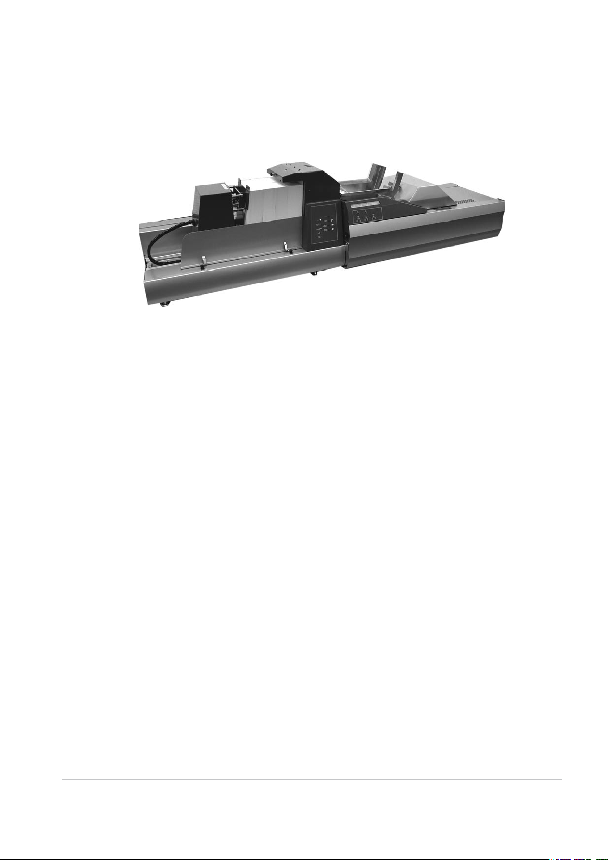
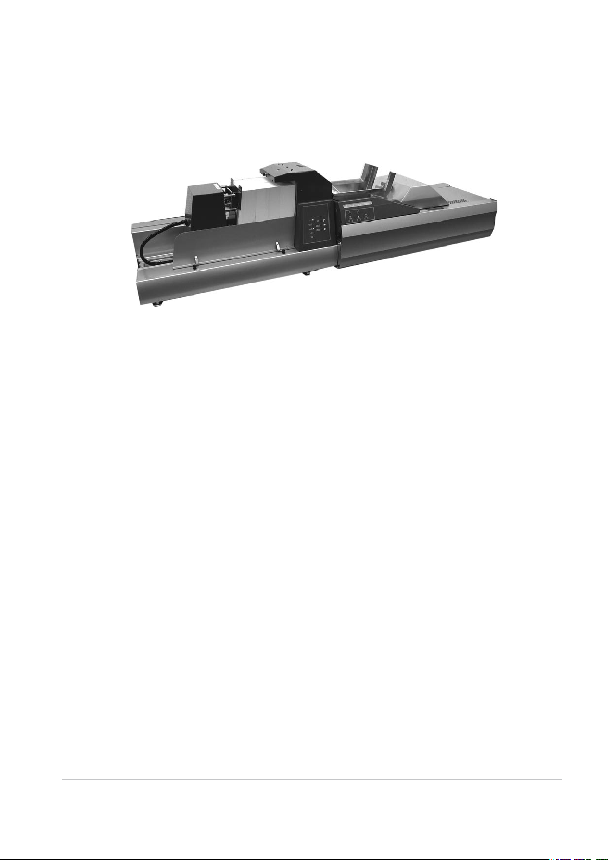
F731 Universal Feeder
F734/F735 High Capacity Loader
1-5
Page 12

1 • Introduction
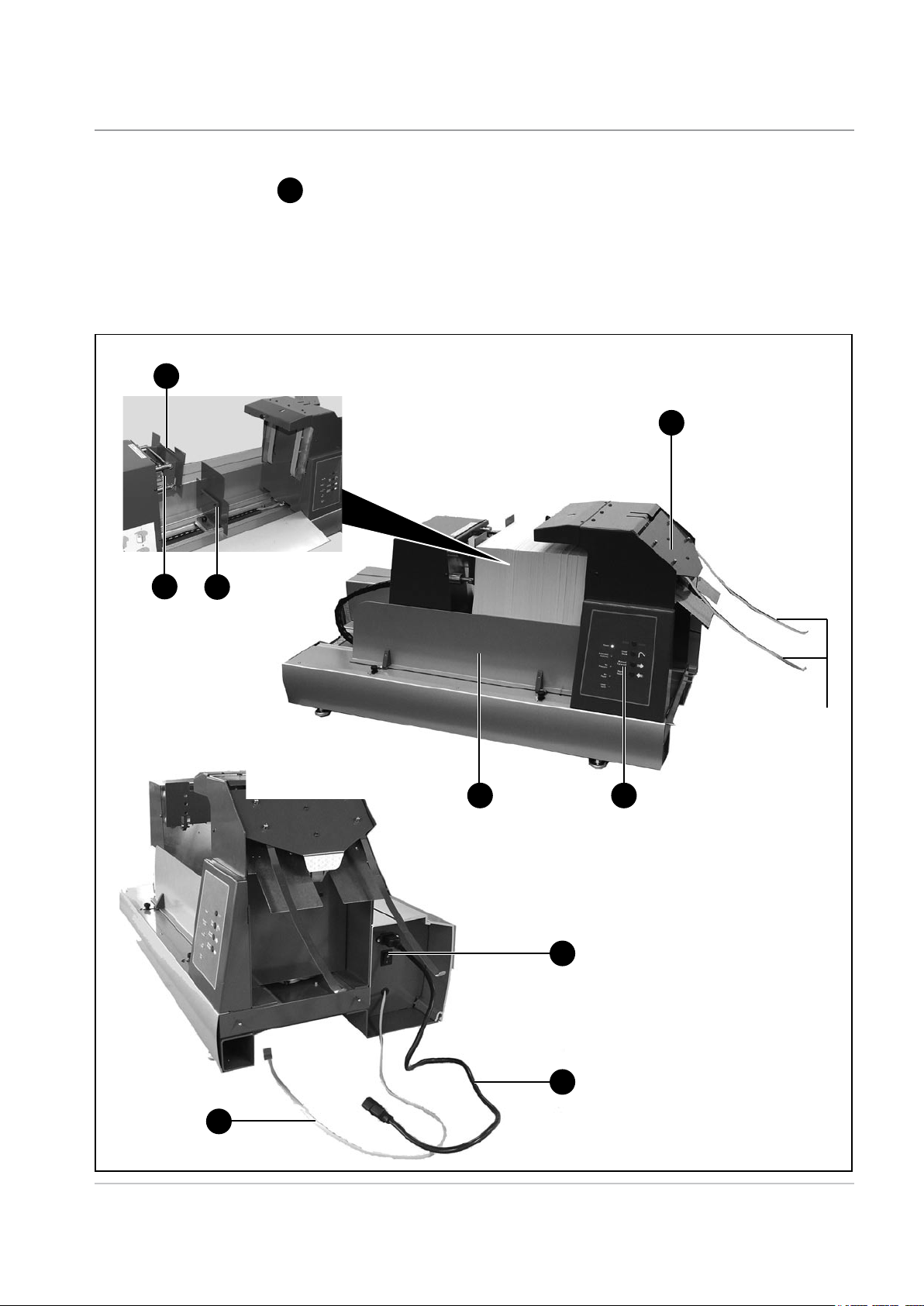
System Components
- F734/F735
1
Front Cover
Provides access to the loading area of the machine. The cover is
interlocked to prevent machine operation when opened.
Material Support Plate
2
This is used to support the material and to keep it upright when
loading material. Move the plate to the left, load material, move the
plate against the material then prepare more material for loading.
Pressure Assembly
3
This assembly will only move when the Front Cover is CLOSED. To
load material, move the Pressure Assembly to the left. After loading,
move the Pressure Assembly against the material. When the machine
is in operation, the Pressure Assembly will automatically monitor the
amount of material and ensure that a constant pressure is applied in
order to ensure continuous, uninterrupted material feed.
4
Pressure Assembly Interrupt
Operation of this plate will interrupt the movement/operation of the
Pressure Assembly and can be used by the operator during the
material loading process.
5
Material Exit Area
Provides access to the material exit area for clearing stalled material.
The cover is interlocked to prevent machine operation when open.
The Guide Strips shown are optional and are only used for 'difficult'
material.
6
Control Panel
Operator controls are conveniently grouped on the front of the High
Capacity Loader. Four controls govern all loading and paper handling
functions. See page 1-10 for details.
7
Power Cord
Connect to the F731 power outlet. See the safety information on page
1-2 before connecting the mains cord.
8
Main Power Switch
Applies power to the F734/F735 High Capacity Loader. This switch is
not accessible when the F734/F735 is docked to the F731 Universal
Feeder. When docked, it should be left in the ON position. The F731
power switch will then control power to both modules.
1-6 SDC790A
Page 13
Introduction • 1
9
System Connector
This should be left connected to the F731 at all times. In particular,
NEVER disconnect it with power applied to the F731 or damage to the
machine may result.
3
5
4
2
Optional
Guide
Strips
1
6
8
SDC790A
7
9
1-7
Page 14

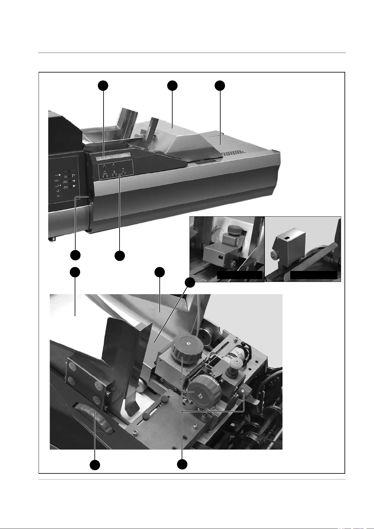
1 • Introduction
System
Components
- F731
1
Top Cover
Provides access to the accumulation area for making adjustments or
clearing stalled material. The cover is interlocked to prevent machine
operation when open.
Feed Deck
2
Equipped with side guides and separator assembly.
Control Panel
3
Operator controls are conveniently grouped on the front of the feeder.
Five multi-function controls govern all programming and paper
handling functions. See page 1-12 for details.
4
Operator Display
The display prompts you through the programming process, shows a
list of available programs and displays error messages.
5
Accumulation Area
Area of the feeder where sheets are collated into sets prior to being
fed into the DI900/DI950 system.
6
Main Power Switch
Applies power to the F731 Universal Feeder.
7
Feeder Head Adjustment Controls (a, b and c)
Adjusts the separator and feed mechanisms so that single items of
material are fed into the accumulation area. Control c adjusts the initial
separation of the material being run. Controls a and b adjust the feed
(take-away) of the single piece of material to the accumulation area.
8
Feeder Side Guides and Control
Used to control the material being fed into the system. Rotate the
control to adjust the guides.
Loader Control Sensor (t)
9
This sensor is only supplied if an F734/F735 High Capacity Loader is
used in the system. It must be fitted onto the F731 Feeder Head (as
shown in the illustration) whenever the F734/F735 is being used. If
the F731 Universal Feeder is being used without the F734/F735, the
sensor must be removed from the Feeder Head and stored in the two
slots in the F731 Rear Cover
1-8 SDC790A
Page 15
14 5
Introduction • 1
6
2
3
8
Sensor Fitted Sensor Stored
9
SDC790A
8
7
1-9
Page 16

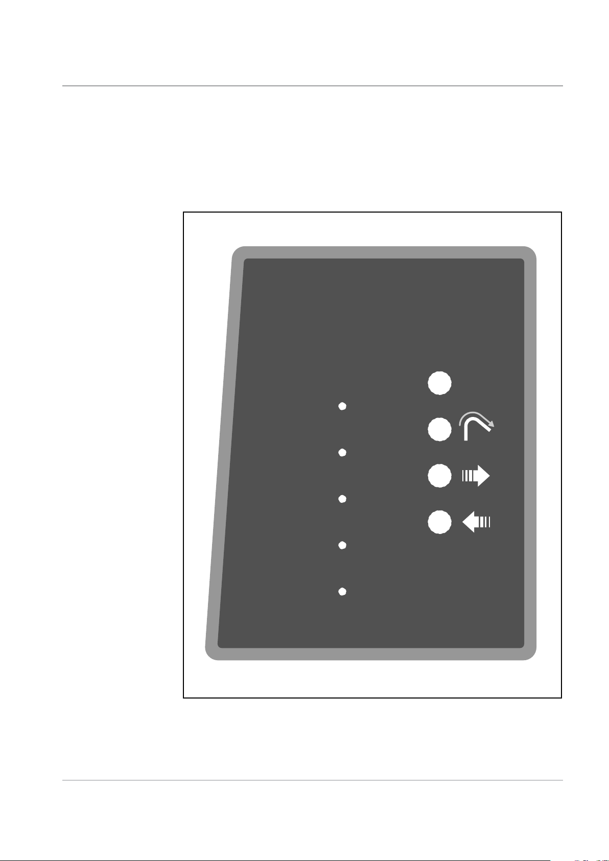
1 • Introduction
Operator Controls
- F734/F735
Manual Reverse Button
With ALL covers closed, press and hold the Manual Reverse Button, the
Pressure Assembly will move to the left. Releasing the button will stop
movement of the Pressure Assembly.
When loading material, you will need to move the Pressure Assembly as
far to the left as is required in order to load your material. When the Manual
Reverse Button is pressed, the No Pressure Indicator light will stay ON.
Manual Forward Button
With ALL covers closed, press and hold the Manual Forward Button, the
Pressure Assembly will move to the right. Releasing the button will stop
movement of the Pressure Assembly.
After loading material, you will need to move the Pressure Assembly to the
right until it contacts the material, and the No Pressure Indicator light goes
OUT.
Clear Deck Button
With ALL covers closed, press and hold the Clear Deck Button. The drive
motors will transport any remaining material out of the machine. Under
normal circumstances it is not necessary to use this button, as the material
would automatically feed out into the F731 Universal Feeder. However, at
the end of a material run, if some material remains in the machine, use the
Clear Deck button to remove it.
Stop/Auto Button
Use this button to set the machine for Automatic operation, after loading
the material. Whenever the Auto mode is active, the Automatic Controls
Indicator light will be ON. If a material stoppage is detected on the F734/
F735, automatic operation is stopped and all the yellow indicator lights on
the Control Panel will FLASH. To reactivate the Automatic mode, simply
press the Stop/Auto Button once.
When the F734/F735 High Capacity Loader is in Auto mode, pressing this
button will stop it immediately.
Power Indicator
The Power Indicator light will stay ON whenever power is applied to the
machine, and the Main Power Switch is ON.
Automatic Controls Indicator
This light will be ON whenever the machine is in Automatic mode.
No Pressure Indicator
This light will be ON whenever there is insufficient pressure on the material.
1-10 SDC790A
Page 17
Introduction • 1
Power
Automatic
Controls
No
Pressure
No
Paper
Cover
Open
AutoStop
Clear
Deck
Manual
Forward
Manual
Reverse
No Paper Indicator
This light will be ON whenever the material supply is exhausted.
Cover Open Indicator
This light will be ON whenever any of the interlocked covers are open.
SDC790A
F734/F735 High Capacity Feeder Control Panel
1-11
Page 18
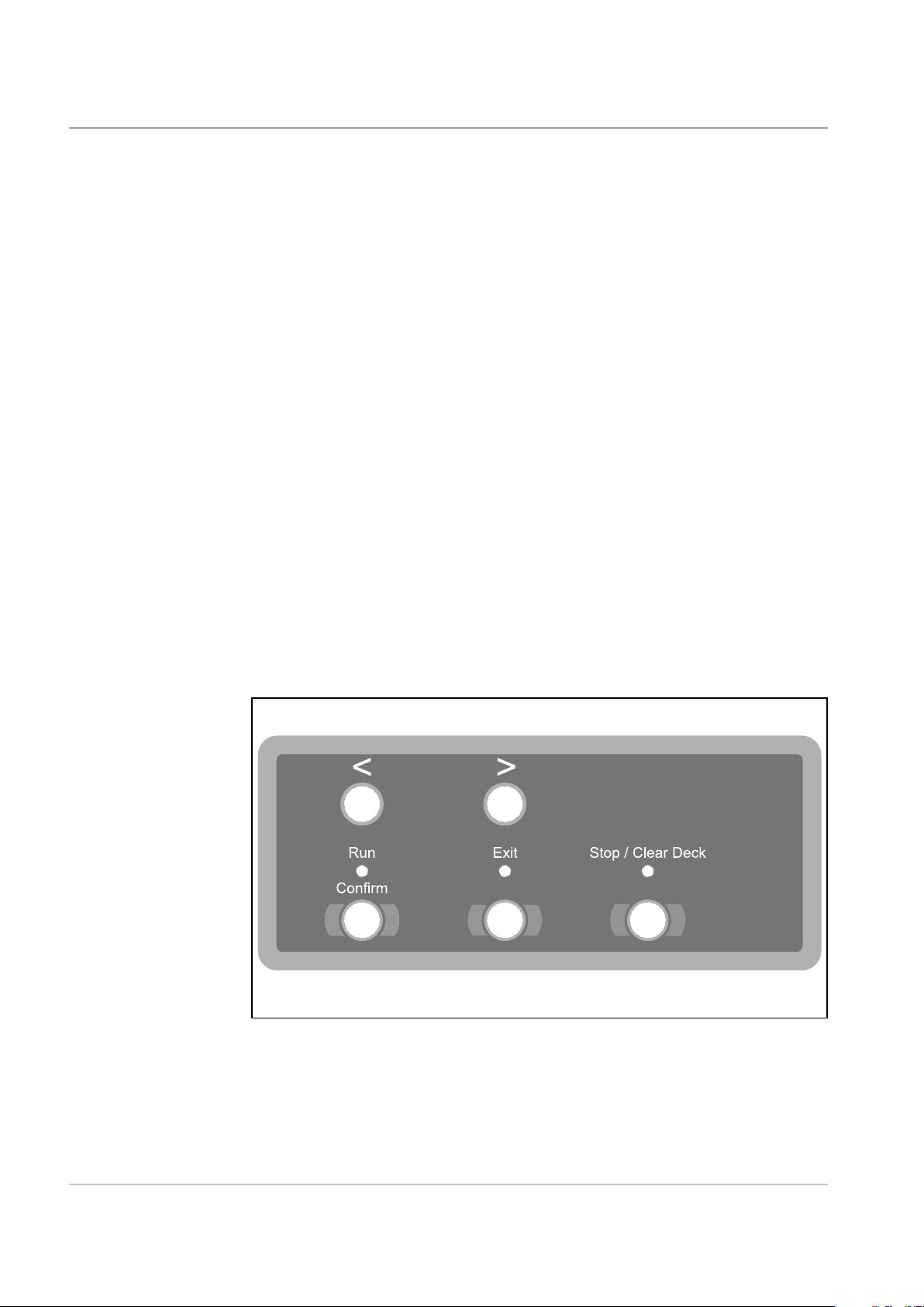
1 • Introduction
Operator
Controls
- F731
Arrow Buttons <>
1. In the operating mode, scroll through available (up to 99) programs in
the program list.
2. In programming mode, select alpha or numeric characters or other
variable settings.
Run Confirm (Green)
In the programming mode, answers YES to prompts.
After set-up with the pre-run adjustments, operation of the SYSTEM
will be through the DI900/DI950 Inserter control panel. This includes
both single cycle (Trial Piece) and continuous operation.
Exit (Blue)
Used when advancing through options in the programming mode.
Stop/Clear Deck (Red)
In the programming mode, answers NO to prompts; also acts as a STOP
button during continuous operation.
If material is in the accumulation area of the F731 i.e. the last set in a job
run, pressing this button will eject the material through the DI900/DI950
Inserting System.
F731 Universal Feeder Control Panel
1-12 SDC790A
Page 19

2 • Operation
This chapter tells you how to setup, load and run the F734/F735 High
Capacity Loader and the F731 Universal Feeder.
F731 Universal Feeder Setup......................................................2-2
Accumulator Input Frame Position ........................................ 2-2
Accumulator Ramp Height ..................................................... 2-2
Power Up ............................................................................... 2-3
Select the Program ................................................................ 2-4
Loading Orientation ............................................................... 2-5
Feeder Side Guides Adjustment ............................................ 2-5
Set the Scanning Head .......................................................... 2-6
Side to Side Adjustment of OMR Scanners ........................... 2-6
Side to Side Adjustment of BCR Scanners ............................ 2-8
Setting the Material Guide Fingers ...................................... 2-10
Feeder Head Adjustment for cut sheets and booklets
up to 2.5mm (3/32") thick ......................................................2-11
Feeder Head Adjustment for booklets 2.5mm (3/32") thick
or greater ..............................................................................2-11
Transport Material to Accumulator ....................................... 2-12
Setting the Accumulator Side Guides .................................. 2-12
Accumulator Ramp Adjustment ........................................... 2-12
Deactivate Inline Test? ........................................................ 2-13
Load Paper .......................................................................... 2-13
F734/F735 High Capacity Loader Setup ...................................2-14
Set the DI900/DI950 System .....................................................2-16
Running the System ..................................................................2-17
2-1SDC790A
Page 20
2 • Operation
F731 Universal Feeder Setup
Accumulator
Input Frame
Position
This section explains how to select a program and set the F731 for the
material being run:
NOTE:
A support latch will engage each
time the Top Cover is opened.
It is necessary to manually release
this latch in order to close the Top
Cover.
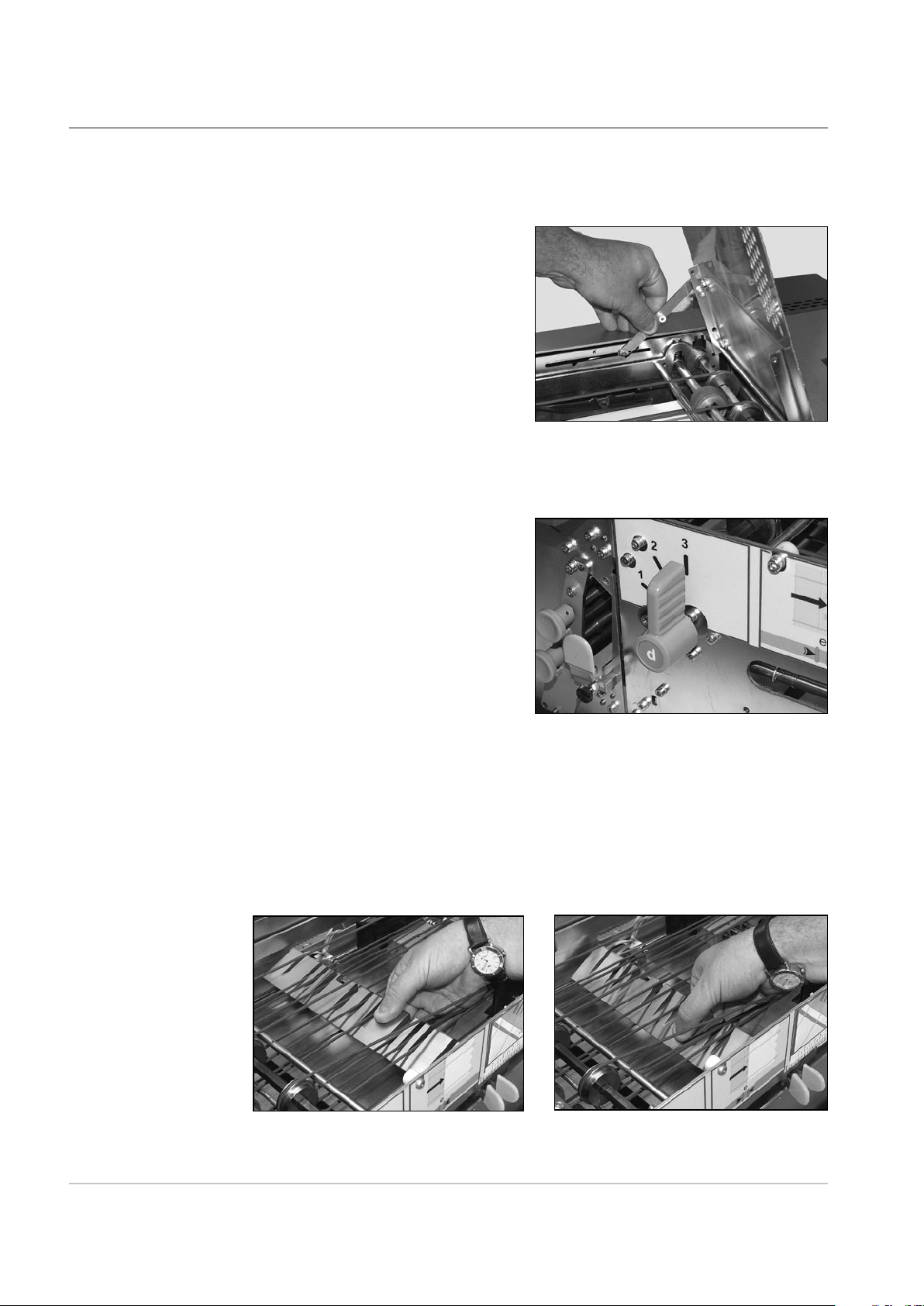
Lower the F731 Front Cover.
Set lever d to the required position:
3 for sheets
2 for thin booklets up to
2.5mm (3/32") thick
1 for thick booklets up to
4mm (5/32") thick
Close the Front Cover.
Accumulator
Ramp Height
2-2 SDC790A
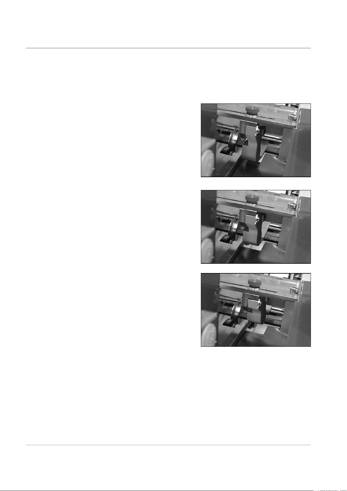
Open the Top Cover.
The ramp must be set to the raised position for sheets or the lowered
position for booklets. Simply grasp the ramp and set it to the required
position.
Raised for sheets Lowered for booklets
Page 21

NOTE:
If the reverse accumulator kit is fitted
to your machine, the ramp height
has three settings controlled by the
position of the lever f located inside
the Front Cover:
1 for reverse accumulate of sheets
i.e. sheet order …3, 2, 1,
2 for booklets
3 for forward accumulate of sheets
i.e. sheet order 1, 2, 3….
Operation • 2
Power Up
Before turning the system ON, refer to the Important Safety Notes on
page 1-2.
Turn the F731 Main Power Switch ON. The F731 will momentarily display
the version number of the software, and then show the listing of available
programs. The Exit (Blue) indicator will light.
Program Listing
012: JOB1 PAPER/DF C=1 <PROG
013: JOB2 PAPER/DF C=1 USB
USB indicates that
the USB link to the
DI900/DI950 Inserter
is operational.
HINT:
If nothing happens, turn the Main Power Switch OFF. Make sure all covers
are closed, then turn the Main Power Switch ON again.
SDC790A
2-3
Page 22

2 • Operation
Select the
Program
The instructions which follow assume that the program you want is available
from the list in the machine’s memory. If necessary, see ‘Adding a NonScanning Program’ on page 3-2, or ‘Adding a Scanning Program’ on page
3-5 for programming instructions.
The display will show the last program run on the top line. Use the Arrow
Buttons to scroll through the list of available programs.
To select a program, scroll so it appears on the first line of the display as
indicated by the arrow and <PROG prompt. Press the Green button to
select the program.
New program. Pre run adjustments?
Green=YES Blue=EXIT Red=NO
The display asks if you wish to run pre-run adjustments. If this is a new job,
press Green and carry out the adjustments as described on pages 2-5 to
2-13. If it is the current job, or the pre-run adjustments have already been
completed, then press Red.
Number of sheets
in each collated set
Material and
Program Name
Handling Options
Loading Orientation
JOB1 PAPER/DF C=1 ORIENTATION 3
Count: 00 Total: 000000 R... Speed: 100%
'Live' count of
sheets fed in
current collation
The display shows the program selected and the main program options.
To set speed, use the Arrow Buttons until the speed you want is displayed.
You may need to adjust the speed when running booklets or certain paper
finishes.
Total Count for
this job run
R shows the
F731 is ready
OMR status
- see page 2-17
Speed selected
DI900/DI950
Inserter signal
confirmation
- see page 2-17
2-4 SDC790A
Page 23

Operation • 2
Loading
Orientation
The Loading Orientation is shown when you select a program. There are
four possible loading orientations:
1 Face up, bottom first
2 Face up, top first
3 Face down, bottom first
4 Face down, top first
When feeding individual pieces of material during setup, or when loading
material prior to a job run, it is important to observe the correct loading
orientation for the program selected.
Feeder Side
Guides
Adjustment
Rotate the Feeder Side Guide
adjusting wheel anticlockwise until
the side guides are wider apart
than the material to be run.
Place a sheet or booklet onto the
Feed Deck.
Turn the Feeder Side Guide
adjusting wheel clockwise to close
the side guides up to the sheet or
booklet, then turn it anticlockwise
6 notches allowing an overall
clearance of approximately 3mm
(0.1") between the material and
guides.
SDC790A
2-5
Page 24

2 • Operation
Set the Scanning
Head
Side to Side
Adjustment of
OMR Scanners
The Scanning Head is used to read OMR/BCR/OCR/2D Matrix scan marks
printed on your material. If you are using this option, carry out the following
settings. If you don’t use this option, continue with ‘Setting the Material
Guide Fingers’ on page 2-10.
Bottom Scanning
Connect power and turn ON. Open the Top and Front Covers.
Open the separator. Unlock lever
a, turn knob b clockwise as far as
it will go and hold in position while
locking lever a.
The OMR scan marks are read from the underside of the sheet and so to be
able to set the scanner position, you must mark their position on the upper
face of the sheet.
Slide a sheet under the separator
and observe the scanner beam on
the sheet.
Adjust the scanner side to side until
the beam is centred on the scan
marks. Use the top adjusting knob
for rear scanning and the lower
knob for front scanning.
Close the covers.
2-6 SDC790A
Page 25

Top Scanning
Connect power and turn ON. Open the Top Cover.
Open the separator. Unlock lever
a, turn knob b clockwise as far as
it will go and hold in position while
locking lever a.
Slide a sheet under the separator
and observe the scanner beam on
the sheet.
Operation • 2
Adjust the scanner side to side
until the beam is centred on the
scan marks. Loosen the knurled
knob shown, align the scanner and
retighten the knob.
Close the cover.
SDC790A
2-7
Page 26

2 • Operation
Side to side
Adjustment of
BCR Scanners
Bottom Scanning
Connect power and turn ON. Open the Top and Front Covers.
Open the separator. Unlock lever
a, turn knob b clockwise as far as
it will go and hold in position while
locking lever a.
The BCR marks are read from the underside of the sheet and so to be able
to set the scanner position, you must mark their position on the upper face
of the sheet.
Press the Green, Blue and Red buttons at the same time to enter the Menu.
Use the Arrow Buttons to select 'User Menu', then press Green to confirm.
Use the Arrow Buttons to select 'BCR Test', then press Green to confirm.
If your system has more than one BCR scanner, use the Arrow Buttons to
select 'BCR Location', then press Green to confirm. Select the location of
the scanner you wish to test, then press Green to confirm.
Slide a sheet under the separator
and observe the scanner beam on
the sheet.
2
Adjust the scanner side to side until
the marks are centred on the beam
area.
Unscrew the locking knob 1. Grasp
handle 2, slide the scanning head
out and reposition the scanning
head. Slide the unit back into the machine and check the alignment.
When in 'BCR Test', the scanner red lights will flash slowly. If the code is
read successfully i.e. the scanner is correctly aligned, the lights will flash
faster and the characters read will display on the operator display.
When the scanner is positioned correctly, tighten locking knob 1.
Exit from the User Menu and close the covers.
1
2-8 SDC790A
Page 27

Operation • 2
Top Scanning
Connect power and turn ON. Open the Top Cover.
Open the separator. Unlock lever
a, turn knob b clockwise as far as
it will go and hold in position while
locking lever a.
Press the Green, Blue and Red buttons at the same time to enter the
Menu. Use the Arrow Buttons to select 'User Menu', then press Green to
confirm. Use the Arrow Buttons to select 'BCR Test', then press Green to
confirm.
If your system has more than one BCR scanner, use the Arrow Buttons to
select 'BCR Location', then press Green to confirm. Select the location of
the scanner you wish to test, then press Green to confirm.
Slide a sheet under the separator and observe the scanner beam on the
sheet.
Adjust the scanner side to side until
the marks are centred on the beam
area.
When in 'BCR Test', the scanner
red lights will flash slowly. If the
code is read successfully i.e. the
scanner is correctly aligned, the
lights will flash faster and the
characters read will display on the
operator display.
When the scanner is positioned correctly, exit from the User Menu.
Close the cover.
SDC790A
2-9
Page 28
2 • Operation
Setting the
Material Guide
Fingers
Open the Top Cover.
The guide fingers can be raised or lowered into one of three detented
positions, depending on the material being run:
Lowered for sheets.
Mid position for thin booklets of
approx. 2.5mm (3/32") thickness.
Raised for thick booklets up to
4mm (5/32") thickness.
Loosen the knurled locking knobs and adjust the guide fingers side to side
to control material. If bottom scanning is being used, one of the guide fingers
must be positioned directly above the scanning head to control the material
as it is scanned.
Close the cover.
2-10 SDC790A
Page 29

Operation • 2
Feeder Head
Adjustment for
cut sheets and
booklets up to
2.5mm (3/32”)
thick
Open the Top Cover.
Turn knob c anticlockwise until it
stops.
Unlock lever a and, with no
material in the feeder, let the
Feeder Head come to rest.
Turn knob b anticlockwise as far as it will go, hold knob b in place and lock
lever a.
Close all covers and press the Run Confirm (Green) button to make the
feeder motor run.
Take two pieces of the material to be run and feed them, by hand, into the
separator. If both pieces feed completely under the separator, pull them out
and tighten knob c clockwise slightly.
Feeder Head
Adjustment for
booklets 2.5mm
(3/32”) thick or
greater
Repeat the previous step until only one piece feeds completely and the
second piece is held back.
Open the F731 Top Cover.
Turn knob c anticlockwise until it stops.
Unlock lever a, then turn knob b clockwise all the way and hold.
Place a booklet all the way under the first and second rollers.
Release knob b so that the Feeder Head rests on the booklet.
Rotate knob b anticlockwise 8 divisions on the scale and hold in this
position whilst locking lever a.
Try to slide a second booklet under the separator. If it goes under, pull it
back and turn knob c clockwise enough that a second booklet cannot slide
under the separator.
SDC790A
Close the cover.
2-11
Page 30

2 • Operation
Transport
Material to
Accumulator
Setting the
Accumulator
Side Guides
Lower the Front Cover and turn
knob g anticlockwise to open the
Accumulator Side Guides. Close
the Front Cover.
Load a sheet or booklet.
Press Run Confirm (Green) until
a piece is fed into the accumulator
area.
Raise the F731 Top Cover and
lower the Front Cover.
Rotate knob g clockwise to set the
Accumulator Side Guides. The
correct setting allows approximately
3mm (0.1") overall clearance so
that the material is controlled but
not restricted.
Accumulator
Ramp
Adjustment
2-12 SDC790A
Ensure a piece of material is in
the accumulator area as in the
Accumulator Side Guide setting
above.
Squeeze the tabs e together and
slide the ramp until the yellow
indicators on the ramp align with
the material rear edge.
Close all covers.
Page 31

Operation • 2
Deactivate Inline
Test?
Load Paper
The normal response to this is to select Green to deactivate, and the
material will transport from F731 to the Inserter.
TIP:
Should you want to test any aspect
of the job setup before the material
is transported to the inserter, select
Red (No) to the prompt and the
sheets will be stacked in the F733
Outsort Tray.
You only need to carry out this step if you are NOT using the F734/F735
High Capacity Loader. If the loader IS being used, it will automatically load
sheets onto the F731's Feed Deck. See F734/F735 setup on the next page.
Flex and aerate the material stack to
ensure good separation.
SDC790A
Position the stack on the Feed Deck
in the correct orientation for the job
being run:
1 Face up, bottom first
2 Face up, top first
3 Face down, bottom first
4 Face down, top first
IMPORTANT: Fan the paper stack as
shown in the photograph.
TIP:
When initially loading the paper stack, load about 200 sheets then fully load
the feeder once you commence operation. The F731 can be reloaded while
the system is in operation.
If you are not using a F734/F735 High Capacity Loader, go straight to 'Set
the DI900/DI950 System' on page 2-16.
2-13
Page 32

2 • Operation
F734/F735 High Capacity Loader Setup
The F734/F735 High Capacity Loader is an optional unit. If you are not using
the loader, continue with 'Set the DI900/DI950 System' on page 2-16.
Make sure the Loader Control
Sensor t is located onto the F731
Feeder Head.
Press and hold the Manual
Reverse Button until the Pressure
Assembly is far enough to the left.
Open the Front Cover and move
the Material Support Plate to the
left.
Before loading material, you need to ascertain its loading orientation. This
depends on the job settings. The F731 job display will indicate which loading
orientation is required for the job (numbered 1 to 4).
The four possible loading
orientations are illustrated on a
label located behind the F734/F735
Front Cover:
1 Face up, bottom first (as fed
into the F731 feeder)
2 Face up, top first (as fed into
the F731 feeder)
3 Face down, bottom first (as fed
into the F731 feeder)
4 Face down, top first (as fed into
the F731 feeder)
Load material up against the right
hand side of the loader flat against
the Feed Belts.
2-14 SDC790A
Page 33

Operation • 2
Push the Material Support Plate
up against each individual batch of
material during the loading process
to support it while you fetch the
next batch.
Important Loading Tips
• When loading the first batch of sheets, do not slide the material in from
the front across the Feed Belts, as this will cause the first couple of
sheets to twist and jam. Instead move the paper from left to right, up to
the Feed Belts. For subsequent batches of material you can slide the
sheets in from the front, between the material already loaded and the
Material Support Plate.
• Once you have completed
the loading process, it is
recommended that you push
the entire paper stack towards
the right using the Material
Support Plate. This will ensure
that the material stack is kept
upright and that all the air is
removed from between the
individual sheets.
SDC790A
If the material is curled along the
top edge, the separation can be
adjusted by rotating the Separator
Adjustment Knob as required.
Rotate the knob anticlockwise for
curled material, but move the knob
in small increments – 2 to 3mm
(approx.. 1/10") maximum.
2-15
Page 34

2 • Operation
Close the Front Cover.
Press and hold the Manual
Forward Button until the Pressure
Assembly is fully to the right, and
the No Pressure Indicator light is
OFF.
Set the DI900/ DI950 System
Press the Stop/Auto Button. The
Automatic Controls Indicator light
will now be ON. The machine is
ready.
You must now set the rest of the DI900/DI950 system to accept the material
from the F731. Details are given in the separate DI900/DI950 Operator
Guide.
2-16 SDC790A
Page 35

Operation • 2
Running the System
Once a program is selected and material loaded, the F731 is controlled
by the DI900/DI950 Inserting System's control panel. Use the DI900/
DI950 controls to run a Trial Piece and to start and stop continuous
operation.
If the F731 is running an OMR program, three blocks will show on the
display as illustrated below. When running non-OMR jobs, blocks 2 and 3
only will show on the display.
JOB1 PAPER/DF C=1 ORIENTATION 3
Count: 00 Total: 000000 R Speed: 100%
Block 1
Block 2
Block 3
Block 1 shows that the F731 has read the first scan dash mark on the
page, indicating that the scanning system is functioning.
Block 2 shows that the F731 has confirmed to the Inserter that the
collation on the conveyor is ready for transfer into the
Inserter.
Block 3 indicates that the Inserter has sent back a collation signal to
the F731.
SDC790A
The F731 will continue operation until:
• You stop it by pressing
or
• You open one of the covers. The safety interlock switch will stop the
machine.
or
•
The material runs out or stalls. In this case the machine will stop
automatically.
TIP:
At the completion of each job run, it is recommended that you check the
two trays in the F733 Outsort Tray for diverted sets.
Stop/Clear Deck (Red).
2-17
Page 36

2 • Operation
2-18 SDC790A
Page 37

3 • Programming
This chapter explains how to program and manage jobs that can be
held in the F731 Universal Feeder's memory.
About Programming Jobs ............................................................3-2
Adding a Non-Scanning Program ................................................3-2
Adding a Scanning Program........................................................3-5
Programming an 'OMR DI900/DI950' Job ............................. 3-5
Programming a 'BCR Standard' Job .....................................3-11
Deleting a Program....................................................................3-13
Modifying a Program .................................................................3-14
3-1SDC790A
Page 38

3 • Programming
About Programming Jobs
Adding a Non-Scanning Program
The F731's memory holds up to 99 pre-programmed jobs that you can recall
with a few button presses.
This chapter explains how to program jobs into the system. It commences
with a non-scanning job and follows with some examples of typical scanning
jobs.
The range of scanning options and job requirements available mean that not
all possibilities can be covered in a document such as this. The examples
chosen will allow you to understand the programming procedure so that you
can adapt it to meet your individual requirements.
This section covers programming a job where scanning is not required. To
program the feeder for a scanning job, see page 3-5. When you program the
F731 for a particular non-scanning job, you:
• Assign the job a name and/or number
• Enter a batch count (if required)
HINT: We advise you keep a ‘hard copy’ of all your programmed jobs for
your own future reference.
Step-by-Step Instructions
With the feeder ON, press the Green, Blue and Red buttons at the same
time. The display will show:
Select: NEW NON-SCANNING JOB
<-->=SELECT Green=Confirm Blue=EXIT
Press the Green button to select ‘NEW NON-SCANNING JOB’.
NOTE: If you press the Blue button, you will return to the job listing screen.
The display shows the program naming screen:
017> Name of new program :
--------
<-->=ALPHA Green=CONFIRM Red=GO ON
You can enter a program name up to eight characters long, using any
combination of alpha and numeric characters.
Use the Arrow Buttons until the first character of your program name
appears.
3-2 SDC790A
Page 39

Programming • 3
Press the Green button to confirm each character.
When the name is complete, press Red to continue. The display shows the
material selection screen:
017> Material: PAPER/DF
<-->=SELECT Green=CONFIRM Blue=EXIT
Use the Arrow Buttons to select the material for this job:
Paper/DF Sheets with double detect turned ON (default setting).
This will be the most common setting for sheets.
Paper Sheets with the double detect turned OFF. This is not
recommended as the feeder will not sense double
feeds. Select this mode for material (sheets) above
160g/m2 (42 lb).
Booklet Booklets with separator motor turned OFF. This is the
normal mode for booklets. Double Detect is disabled
with this mode.
Booklet/RM Booklets with separator motor turned ON. This is
used for special applications. Double Detect is
disabled with this mode.
Paper/DF+ Sheets with double detect turned on at a custom
setting. This is normally used for sheets with
heavily printed block areas and will be used only on
advice from your service representative.
Press Green to confirm your selection. The display shows the material
loading orientation selection:
017> Loading orientation : 3.DOWN-BOTTOM
<-->=SELECT Green=CONFIRM Blue=EXIT
Use the Arrow Buttons to select the material loading orientation:
1 Face up, bottom first
2 Face up, top first
3 Face down, bottom first
4 Face down, top first
SDC790A
Press Green to confirm your selection. The display shows the counter
selection:
3-3
Page 40

3 • Programming
Setting a count tells the feeder how many sheets are in each collated set.
The F731 will collate the requested number of forms before transporting
them into the DI900/DI950 system. The default setting is 01 – a single sheet
insert (one piece per cycle). The count can be set from 01 to 25.
017> Counter : 01 Sheets
<-->=VALUE Green=CONFIRM Red=GO ON
a. Use the
then press Green to enter the number.
b. Repeat this process for the second digit.
The display will return to the program listing display.
Programming a non-scanning job is now complete.
Arrow Buttons until the first number of your entry appears,
3-4 SDC790A
Page 41

Programming • 3
Adding a Scanning Program
Programming
an 'OMR DI900/
DI950 Job
Background information on scanning is given in the DI900/DI950 Operating
Guide. This section assumes you understand scanning and how it applies
to the job you are programming. It also assumes you are familiar with
programming non-scanning jobs as described on page 3-2.
NOTE: If you select booklets, no scanning is available.
The following sections give two examples of setting up scanning jobs. One
for OMR scanning and one for BCR scanning.
HINT: We advise you keep a ‘hard copy’ of all your programmed jobs for
your own future reference.
When you program the feeder for an OMR scanning job, you enter the
program in a similar way as a non-scanning job, then…
• Specify the
• Select the scan functions you wish to use
• Specify the distance from the lead edge to the
• Specify where each scan line is in relation to the first line
scan line increments
bench mark
Step by Step Instructions
With the feeder ON, press the Green, Blue and Red buttons at the same
time. The display shows the program type selection:
Select: NEW NON-SCANNING JOB
<-->=SELECT Green=Confirm Blue=EXIT
Press the Arrow Buttons to select ‘NEW SCANNING JOB’.
Select: NEW SCANNING JOB
<-->=SELECT Green=Confirm Blue=EXIT
Press Green to enter the scanning programming mode.
The display shows the program naming screen:
SDC790A
3-5
Page 42

3 • Programming
018> Name of new program :
--------
<-->=ALPHA Green=CONFIRM Red=GO ON
You can enter a program name up to eight characters long, using any
combination of alpha and numeric characters.
Use the Arrow Buttons until the first character of your program name
appears.
Press the Green button to confirm each character.
When the name is complete, press Red to continue. The display shows the
material selection screen:
018> Material: PAPER/DF
<-->=SELECT Green=CONFIRM Blue=EXIT
Use the Arrow Buttons to select the material for this job:
Paper/DF Sheets with double detect turned ON (default setting).
This will be the most common setting for sheets.
Paper Sheets with the double detect turned OFF. This is not
recommended as the feeder will not sense double
feeds. Select this mode for material (sheets) above
160g/m2 (42 lb).
Booklet This function is not used in scanning mode.
Booklet/RM This function is not used in scanning mode.
Paper/DF+ Sheets with double detect turned on at a custom
setting. This is normally used for sheets with
heavily printed block areas and will be used only on
advice from your service representative.
Press Green to confirm your selection. The display shows the material
loading orientation selection:
018> Loading orientation : 3.DOWN-BOTTOM
<-->=SELECT Green=CONFIRM Blue=EXIT
3-6 SDC790A
Page 43

Programming • 3
Use the Arrow Buttons to select the material loading orientation:
1 Face up, bottom first
2 Face up, top first
3 Face down, bottom first
4 Face down, top first
Press Green to confirm your selection. The display requests the scanning
version:
018> Vers.: OMR DI900/DI950
<-->=SELECT Green=CONFIRM Blue=EXIT
Use the Arrow Buttons to select which scanning mode you want. In this
example, select ‘OMR DI900/DI950'.
Press Green to confirm. The display requests the OMR scanner location:
018> OMR location : BOTTOM-FRONT
Green=CONFIRM Blue=EXIT
If you have more than one scanning head fitted to your system, you must
now tell the system which scanning head to use for this job.
If you only have one scanning head, this step is not required.
Use the Arrow Buttons to select where the OMR scanner is located:
Bottom Rear, Bottom Front, Top Rear or Top Front.
Press Green to confirm. The display shows the scan line increment
selection:
018> Scan line increments : 1/6 Inch
<-->=SELECT Green=CONFIRM Blue=EXIT
Use the Arrow Buttons to select the scan line increments. You can select
one of the three (1/6", 1/8" or 1/10") scan line increments shown, or you can
select a custom ‘User Defined’ increment. Press Green to confirm.
If you select ‘User Defined’, you must now enter the increment:
SDC790A
018> Scan line increments :
[0.01MM]
---
<-->=SELECT Green=CONFIRM Blue=EXIT
Take a sample of your OMR with the largest number of scan lines you can
obtain. Measure the length of the code in millimetres, and then divide this by
the number of gaps between lines to obtain an average increment.
3-7
Page 44

3 • Programming
Example: 26mm code length with 6 scan lines gives an increment of 26
divided by 5 (the number of gaps) = 5.2mm
Enter this increment using the Arrow Buttons. The figure entered is in units
of 0.01mm i.e. in the example above 5.2mm would be entered as 520. Press
Green to confirm. The display now moves to the scan functions selection:
Use the Arrow Buttons to select the scan functions. For each scan line in
order as printed on the page, select the function required and confirm by
pressing Green.
Examples:
Benchmark control in position 1
Benchmark control : [ 1]
<-->=SELECT Green=CONFIRM
Beginning of collation in position 2
Beginning of collation : [ 2]
<-->=SELECT Green=CONF. Blue=END Red=GAP
Select feed 1 in position 3
Select feed 1 : [ 3]
<-->=SELECT Green=CONF. Blue=END Red=GAP
End of collation in position 4
End of collation/present : [ 4]
<-->=SELECT Green=CONF. Blue=END Red=GAP
When the required scan functions are set, press Blue to exit.
HINT:
If you make an error at any time during this process, pressing Red will allow
you to modify your selections.
NOTE:
If your OMR marks are not contiguous (i.e. some mark positions are not
being used), you must define where the unused positions are so that the
system does not interpret the unused positions as an error. After each scan
line function is set, if you wish to insert a gap, press Red, select the number
of scan positions for the gap using the Arrow Buttons and then press
Green to confirm.
UDV (Upstream divert) : [ 3]
<-->=GAP Green=CONF. Blue=END Red=DEL.
3-8 SDC790A
Page 45

Programming • 3
You must now enter the distance from the lead edge to the bench mark:
Dist. lead edge to bench mark : 00 mm
<-->=VALUE Green=CONFIRM Red=GO ON
Use the Arrow Buttons to set the distance, then confirm by pressing
Green. Refer to the diagrams below for details of where to take this
measurement. In each case, dimension X should be entered.
FEED DIRECTION
TOP
BOTTOM
Top first
forward scanning
TOP
BM
BM
FEED DIRECTION
X
reverse scanning
TOP
BOTTOM
Top first
TOP
X
BM
BM
SDC790A
BOTTOM
FEED DIRECTION
Bottom first
reverse scanning
X
BOTTOM
FEED DIRECTION
Bottom first
forward scanning
X
3-9
Page 46

3 • Programming
You now need to tell the system in which direction to read the scan code:
The options available are:
Use the Arrow Buttons to select the option you want, then press Green to
confirm.
018> OMR scanning : NORMAL
<-->=SELECT Green=CONFIRM Blue=EXIT
NORMAL Where the system will expect the Bench Mark to be
the FIRST mark in the scan code.
REVERSE Where the system will expect the Bench Mark to be
the LAST mark in the scan code.
NOTE:
Take into account the direction of feed of your material when making this
setting. i.e. whether the material is being fed top first or bottom first. The
setting selected must match whether the Bench Mark is fed past the scanner
first or last.
The display will return to the program listing display.
Programming an OMR scanning job is now complete.
3-10 SDC790A
Page 47

Programming • 3
Programming a
'BCR Standard'
Job
Step by Step Instructions
With the feeder ON, press the Green, Blue and Red buttons at the same
time. The display will show:
Select: NEW NON-SCANNING JOB
<-->=SELECT Green=Confirm Blue=EXIT
Press the Arrow Buttons to select ‘NEW SCANNING JOB’.
Select: NEW SCANNING JOB
<-->=SELECT Green=Confirm Blue=EXIT
Press the Green button to enter the scanning programming mode. The
display will show the program naming screen:
019> Name of new program :
--------
<-->=ALPHA Green=CONFIRM Red=GO ON
You can enter a program name up to eight characters long, using any
combination of alpha and numeric characters.
Use the Arrow Buttons until the first character of your program name
appears.
Press the Green button to confirm each character.
When the name is complete, press Red to continue.
The display shows the material selection screen:
019> Material: PAPER/DF
<-->=SELECT Green=CONFIRM Blue=EXIT
Use the Arrow Buttons to select the material for this job:
SDC790A
3-11
Page 48

3 • Programming
Paper/DF Sheets with double detect turned ON (default setting).
This will be the most common setting for sheets.
Paper Sheets with the double detect turned OFF. This is not
recommended as the feeder will not sense double
feeds. Select this mode for material (sheets) above
160 g/m2 (42 lb).
Booklet This function is not used in scanning mode.
Booklet/RM This function is not used in scanning mode.
Paper/DF+ Sheets with double detect turned on at a custom
setting. This is normally used for sheets with
heavily printed block areas and will be used only on
advice from your service representative.
Press Green to confirm your selection. The display shows the material
loading orientation selection:
019> Loading orientation : 3.DOWN-BOTTOM
<-->=SELECT Green=CONFIRM Blue=EXIT
Use the Arrow Buttons to select the material loading orientation:
1 Face up, bottom first
2 Face up, top first
3 Face down, bottom first
4 Face down, top first
Press Green to confirm your selection. The display requests the scanning
version:
019> Vers.: BCR Standard
<-->=SELECT Green=CONFIRM Blue=EXIT
Use the Arrow Buttons to select which scanning mode you want. In this
example, select ‘BCR Standard’. Press Green to confirm.
The display will now ask where the BCR Scanner is located:
3-12 SDC790A
Page 49

Programming • 3
019> BCR location : Top Front
<-->=SELECT Green=CONFIRM Blue=EXIT
Use the Arrow Buttons to select where the BCR scanner is located,
Bottom Rear, Bottom Front, Top Rear or Top Front. Press Green to confirm.
Programming a BCR scanning job is now complete.
Deleting a Program
With the feeder ON, press the Green, Blue and Red buttons at the same
time. The display will show:
Select: NEW NON-SCANNING JOB
<-->=SELECT Green=Confirm Blue=EXIT
Use the Arrow Buttons to select ‘DELETE JOB’.
Select: DELETE JOB
<-->=SELECT Green=Confirm Blue=EXIT
Press the Green button to enter the job delete mode.
Use the Arrow Buttons to display the program you want to delete on the
top line of the display.
CAUTION: Make sure you’ve selected the right program and that you
really want to delete it. You can’t recover a deleted program. If you
accidentally delete a program, you’ll have to reprogram the feeder for
that particular job.
SDC790A
Press the Green button to delete the program.
The display will briefly prompt 'Program ******** Deleted' and return to the
program listing.
3-13
Page 50

3 • Programming
Modifying a Program
With the feeder ON, press the Green, Blue and Red buttons at the same
time. The display will show:
Select: NEW NON-SCANNING JOB
<-->=SELECT Green=Confirm Blue=EXIT
Use the Arrow Buttons to select ‘MODIFY JOB’.
Select: MODIFY JOB
<-->=SELECT Green=Confirm Blue=EXIT
Press the Green button to enter the job modify mode.
Use the Arrow Buttons to display the program you want to modify on the
top line of the display. Then press the Green button to select it.
You can now review the job using the Arrow Buttons. You can also edit any
of the following parameters:
• Name of program
• Material
• Loading
• Counter (non-scanning job only)
• Scan line increments (scanning job only)
• Distance – Lead edge to
To edit any of these parameters, with the parameter displayed:
• Press the
• P
ress the Arrow Buttons to make the change.
• Confirm the change by pressing the
orientation
bench mark (scanning job only)
Green button to select the parameter.
Green button.
3-14 SDC790A
Page 51

4 • Troubleshooting &
Maintenance
This chapter will help you should you have any problems whilst
running your system. It also describes the regular maintenance
operations that you can carry out to maintain optimum system
performance.
The User's Menu .........................................................................4-2
Options Available ................................................................... 4-2
Handling Material Stoppages ......................................................4-3
Stoppages in the F731 Universal Feeder .............................. 4-3
Stoppages in the F734/F735 High Capacity Loader .............. 4-4
Troubleshooting Charts ...............................................................4-5
Troubleshooting Using the F731 Scan Error Screens .................4-7
Operator Maintenance .................................................................4-8
4-1SDC790A
Page 52

4 • Troubleshooting & Maintenance
The User’s Menu
Options
Available
To access the User Menu functions:
Press the Green, Blue and Red buttons at the same time.
Use the Arrow Buttons to select ‘User Menu’, then press Green to confirm.
Select: USER MENU
<-->=SELECT Green=Confirm Blue=EXIT
The User Menu offers the options listed below. Use the Arrow Buttons to
select an option, then press Green to confirm.
When you are finished with any option, press Red to go to the next
selection.
Material Feed Belt Cleaning
The Material Feed Belts should be cleaned if the belts appear contaminated
and/or if material feed is sluggish.
This option allows you to stop and start the belts using the Green button to
facilitate cleaning.
Press the button momentarily and the feed belts will run for approximately 3
seconds. Press and hold the button to run the feed belts continuously.
It is recommended that the material feed belts are cleaned weekly with
water and a good quality cloth.
BCR Test
This function allows you to test that a BCR scanner is reading a code.
When selected, the scanner red lights will flash slowly. Manually position
the bar code above or below the scanner as applicable. If the code is read
successfully, the lights will flash faster and the characters read will display
on the operator display.
Total Feed Cycles
This option displays the total cycles that the F731 has performed.
Motor Test
LED and Key Test
Show Sensor Status
Double Feed Adjust
These are primarily for service use. Only access these options at the
request of a representative of your machine supplier.
4-2 SDC790A
Page 53

Troubleshooting & Maintenance • 4
Handling Material Stoppages
Stoppages in the
F731 Universal
Feeder
This section describes how to clear material stoppages from the F734/F735
High Capacity Loader and the F731 Universal Feeder.
The F731 may stop indicating a misfeed. The indicator on the Stop/Clear
Deck (Red) button will be flashing.
Follow the relevant procedure below:
Feeder Head section…
Remove the material from the Feed Deck.
Open the Top Cover. Unlock lever a and turn knob b fully clockwise and lock
lever a to keep the separator area open.
Carefully clear any material in this
area.
Unlock lever a, turn knob b
anticlockwise as far as it will go and
lock lever a to secure the assembly
closed.
Close the Top Cover, reload the paper
and press Run Confirm (Green) to
restart operation.
SDC790A
Accumulator Area…
Open the Top Cover.
Carefully clear any stalled material,
taking care not to damage the
accumulator drive O rings.
Close the Top Cover.
Press Run Confirm (Green) to restart
operation.
TIP:
If you are running stiff material, it may aid removal if the Accumulator Ramp
e is moved out of the way. Make sure you return the ramp to its original
position after clearing the stoppage.
4-3
Page 54

4 • Troubleshooting & Maintenance
Stoppages in the
F734/F735 High
Capacity Loader
This section describes how to clear material stoppages from the F734/F735
High Capacity Loader and the F731 Universal Feeder.
The F734/F735 may stop and indicate
a misfeed. In this case, ALL the
indicator lights on the Control Panel
will FLASH.
To access any stalled material in the
Feed Section, move the Pressure
Assembly 1 to the left and open the
Front Cover 2.
To access material in the Material Exit
Area, open the cover 3 and remove
any stalled material.
After clearing any stalled material
and closing all the interlocked covers,
remember to press the Stop/Auto
Button once to prepare the machine
for use.
1
2
3
TIP:
Make sure that stoppages in the Material Exit Area are not caused by the
sheets hitting the F731 Feeder Side Guides. Opening the Side Guides
slightly may help in these cases.
4-4 SDC790A
Page 55

Troubleshooting & Maintenance • 4
Troubleshooting Charts
The charts in this section describe problems you may see on your system
and the corrective action(s) you need to take.
Problem Possible Cause
System fails to
start
F731 powers up
but won't display
program list or
displays random
characters.
F731 will not
respond to
controls, display
prompts 'Cover
Open'. Program
button blinks.
No power at outlet. Check the supply circuit breaker
or ON/OFF switch.
Power cord disconnected or Main Power Switch on
F734/F735 or F731 turned OFF.
F731 program has failed to load. Turn F731 Main
Power Switch OFF then ON again to reset. Also
make sure that the covers are securely closed. If
F731 continues to fail at startup, call for service.
A cover is open. Check the F734/F735 Front and
Exit Area Covers and the F731 Front and Top
Covers. Close all covers securely.
F731 will not
respond to
controls. Controls
appear locked.
F734/F735 will
not respond to
controls, yellow
indicator lights
flash.
Material feed
appears slow/
sluggish.
Turn the F731 main power switch OFF then ON
again to reset.
Communication with DI900/DI950 has been
interrupted. Power down all modules together, then
re-power system.
If controls continue to lock, call for service.
A cover is open. Check the F734/F735 Front and
Exit Area Covers and the F731 Front and Top
Covers. Close all covers securely.
Check for an error condition on the F731 display.
Check for correct position of the F731 Feeder Side
Guides (see page 2-5).
Clean the material feed belts (see page 4-2).
Check the Feeder Head/Separator adjustments
(see page 2-11 for the F731 or page 2-15 for the
F734/F735).
SDC790A
4-5
Page 56

4 • Troubleshooting & Maintenance
Problem Possible Cause
Material stops
in the F731
accumulation area.
Display prompts
'Double feed error'.
Material stops in
the separation
area. Display
prompts 'Double
feed error'.
Multiple feed
errors or stream
feed errors.
Feeder display
indicates 'DF
Sensor Out of
Limit'.
Check the Accumulator Side Guide settings (see
page 2-12) and the Ramp settings (see page 2-13).
Wrong program selected from listing.
The F731 has detected a 'Double Feed'. Push the
Stop/Clear Deck button to advance the material
into the accumulator area for error correction. If
double feeds persist, refer to the Feeder Head
adjustment on page 2-11.
Check the Feeder Head adjustment
(see page 2-11).
The material is too thick to be sensed by the double
detection system.
Check that you have selected the correct program
(see page 2-4).
Check that the job is programmed correctly i.e.
'Paper' or 'Booklet' (if appropriate) selected in
material selection to turn double detect off (see
pages 3-2, 3-5 or 3-11).
Feeder display
indicates
'Current Job Not
Compatible'.
Feeder display
indicates 'No
Material for Double
Feed Adjustment'.
Feeder display
indicates 'Wrong
Accumulation
Direction'.
4-6 SDC790A
Check the job setups on the F731 Universal Feeder
AND the material listed for feeder Y on the DI900/
DI950 Inserter to ensure that both have the same
material type and loading orientation.
If scanning is being used, check it is selected in
both the F731 AND the DI900/DI950 programs.
Take a single sheet and load it onto the F731 Feed
Deck (see page 2-5).
Material not being transported to Take-Away Roller.
Adjust Feeder Head settings (see page 2-11).
Check the position of the Accumulator Ramp (see
page 2-2).
Page 57

Troubleshooting & Maintenance • 4
Problem Possible Cause
Feeder display
indicates 'Wrong
Input Frame
Position'.
Feeder display
indicates 'Misfeed
on Conveyor'.
Feeder display
indicates 'Scan
System Error'.
F734/F735 will not
go into automatic
mode.
Check the position of the Input Frame (see page
2-2).
Check the Accumulator Side Guides settings (see
page 2-12).
Check to ensure that the green accumulator belts
are properly installed on all pulleys.
Scanner not positioned correctly above/below the
scan marks (see pages 2-6 and 2-7 for OMR, or
pages 2-8 and 2-9 for BCR).
Scan head may be blocked or dusty. Clean scan
head surface with a soft cloth.
Check that the Input Sensor is properly installed
(see page 2-14).
Check Exit Area Cover is closed.
SDC790A
4-7
Page 58

4 • Troubleshooting & Maintenance
Troubleshooting Using the F731 Scan Error Screens
It is possible to use the Scan Error Screens to check that the Universal
Feeder has read the appropriate scan marks. An example Scan Error
Screen is shown below:
Scan System Error ................- - -
Green=CONFIRM Red=RELOAD PAPER
If some marks are missing or printed in the wrong position on the material,
you will be able to see this by checking the display on the Scan Error
Screen.
a. There should be no marks (black blocks on the display) indicated in the
area shown in the illustration below. If marks are shown, a scanning
error has been detected.
No marks should
appear in this area
Scan System Error ................- - -
Green=CONFIRM Red=RELOAD PAPER
Operator Maintenance
b. Whenever the sheet feeder stops and indicates a scanning error, you
should compare the marks on the Universal Feeder display with those
on the material.
In cases a and b above, examine the page which has been transported
under the scanning head and into the accumulator area. Check the
print quality of the scan dash marks and their positions on the page. If
the material appears to be OK, check the scanning program settings on
the Universal Feeder, especially the setting 'Lead edge to bench mark'
described on page 3-9.
To aid efficient transport through the conveyor sections of the High Capacity
Loader and Universal Feeder, it is recommended that the Material Feed and
Transport Belts are cleaned weekly with water.
The 'Material Feed Belt Cleaning' function within the User Menu can be
used to assist in belt cleaning (see page 4-2).
The external covers of the units can be cleaned using a non-spirit based
cleaner. Always turn power OFF before cleaning the exterior covers of
the system.
4-8 SDC790A
Page 59

5 • Reference
This chapter contains reference information that you might find useful
from time to time.
Service.........................................................................................5-2
Compliance .................................................................................5-2
Equipment Specifications ............................................................5-3
Material Specifications.................................................................5-4
5-1SDC790A
Page 60

5 • Reference
Service
Compliance
Service for your system is available throughout the world.
Should you have questions about your system, or require service or
assistance with your particular application, please call your machine
supplier. Contact details are given at the front of this book or in a separate
document supplied with your system.
Your machine supplier will also offer a service maintenance contract to keep
your system in top condition at nominal cost.
Conforms to the Following:
FCC Rules
This equipment has been tested and found to comply with the limits for a
Class A digital device, pursuant to part 15 of the FCC rules. These limits
are designed to provide reasonable protection against interference when
the equipment is operated in a commercial environment. This equipment
generates, uses, and can radiate radio frequency energy and, if not installed
and used in accordance with the instruction manual, may cause interference
to radio communications. Operation of this equipment in a residential area is
likely to cause interference, in which case the user will be required to correct
the interference at his own expense.
CAUTION: Changes or modifications to this equipment not expressly
approved by the party responsible for compliance could void the user’s
authority to operate the equipment.
It is certified that the system complies with all applicable Directives
of the European Union.
For a formal Declaration of Conformity please contact Compliance
Engineering. Contact information is given in the front of this guide or on a
separate document supplied with your system.
WARNING: This is a Class A product. In a domestic environment this
product may cause radio interference in which case the user may be
required to take adequate measures.
5-2 SDC790A
Page 61

Reference • 5
Equipment Specifications
Electrical
F731: 100-240VAC, 50/60Hz, 5A
F734/F735: 100-240VAC, 50/60Hz, 5A
Physical Dimensions
F731: 480mm High x 600mm Wide x 1000mm Long
(19" High x 23.6" Wide x 39.4" Long)
F734/F735: 500mm High x 500mm Wide x 900mm Long
(19.7" High x 19.7" Wide x 35.4" Long)
Weight
F731: 64kg (141 lb)
F734/F735: 60kg (132 lb)
Speed
Up to a maximum speed of 15,000 sheets per hour.
Noise Level
F731: Below 70 dBA
F734/F735: Below 30 dBA
Operating Temperature Range
Minimum: 10°C (50°F)
Maximum: 35°C (95°F)
SDC790A
5-3
Page 62

5 • Reference
Material Specifications
F731 Universal Feeder
Weight (Sheets)
60g/m2 (16 lb) minimum to 165g/m2 (42 lb) maximum
Thickness (Booklets)
4mm (0.16") maximum
Length (without loader fitted)
175mm (7") minimum to 358mm (14") maximum
Width (without loader fitted)
130mm (5") minimum to 250mm (9.8") maximum
Feed Tray Capacity (without loader fitted)
Up to a maximum stack height of 35mm (1.4").
Can be reloaded whilst running.
F734/F735 High Capacity Loader
Sheet Size
F734: 8.5" x 11" only
F735: DIN A4 size (210mm x 297mm) only
Sheet Weight
60g/m2 (16 lb) minimum to 125g/m2 (33 lb) maximum
Capacity
up to 4,500 sheets
5-4 SDC790A
Page 63

Index
Index-1SDC790A
Page 64

Index
A
About Your System 1-4
Accumulation Area 1-8
Accumulator
Input Frame 2-2
Ramp 2-2
Side Guides 2-12
Transport To 2-12
Arrow Buttons 1-12
Automatic Controls Indicator 1-10
B
Batch Count 3-2
BCR—See Programming/Scanning
BCR Test 4-2
Booklet 3-3, 3-6, 3-12
Settings 2-11
Booklet/RM 3-3, 3-6, 3-12
Button
Arrow 1-12
Clear Deck 1-10
Exit 1-12
Manual Forward 1-10
Manual Reverse 1-10
Run Conrm 1-12
Stop/Auto 1-10
Stop/Clear Deck 1-12
Stop No 1-12
C
CE 5-2
Cleaning
Feed Belts 4-2
Operator Maintenance 4-8
Clear Deck Button 1-10
Compliance 5-2
Contact Information v
Control Panel 1-6, 1-8, 1-10, 1-11, 1-12, 4-4
Count 3-4
Cover Open Indicator 1-11
Curled Material 2-15
D
Deactivate Inline Test 2-13
Deleting a Program 3-13
E
Edit a Program 3-14
Exit Button 1-12
F
F731
About 1-4
Components 1-8
Controls 1-12
Setup 2-2
Stoppages 4-3
F734/F735
About 1-5
Components 1-6
Controls 1-10
Setup 2-14
Stoppages 4-4
Features
F731 1-4
F734/F735 1-5
Feed Deck 1-8, 2-5, 2-13, 4-3, 4-6
Feeder Head 1-8, 2-1, 2-11, 2-14, 4-3, 4-5, 4-6
Feeder Side Guides 1-8, 2-1, 2-5, 4-4, 4-5
Front Cover 1-6, 2-2, 2-12, 2-14, 2-16, 4-4
G
Gap 3-8
Guide Strips 1-6
H
Help
Contact Information v
Troubleshooting 4-1
I
Important Safety Notes 1-2
Indicator
Automatic Controls 1-10
Cover Open 1-11
No Paper 1-11
No Pressure 1-10
Power 1-10
Inline Test
Deactivate 2-13
Index-2 SDC790A
Page 65

Index
J
Jam 4-3, 4-4
L
Latch - Support 2-2
Loader Control Sensor 1-8, 2-14
Loading Orientation 2-5, 2-14, 3-3, 3-6, 3-7, 3-12,
4-6
Loading Tips 2-15
Load Paper 2-13
M
Main Power Switch 1-6, 1-8, 1-10, 2-3, 4-5
Manual Forward Button 1-10
Manual Reverse Button 1-10
Material Curl 2-15
Material Exit Area 1-6, 4-4
Material Feed Belt Cleaning 4-2
Material Guide Fingers 2-6, 2-10
Material Loading 2-13
Material Support Plate 1-6, 2-14, 2-15
Modifying a Program 3-14
N
No Paper Indicator 1-11
No Pressure Indicator 1-10
Normal Scanning 3-10
O
OMR—See Programming/Scanning
Operator Display 1-8
Operator Maintenance 4-8
Operator Note 1-4
Orientation 2-13, 2-14, 3-3, 3-6, 3-7, 3-12, 3-14,
4-6
Outsort 2-13, 2-17
P
Paper 3-3, 3-6, 3-12
Paper/DF 3-3, 3-6, 3-12
Paper/DF+ 3-3, 3-6, 3-12
Power Cord 1-6
Power Indicator 1-10
Power Switch 1-6, 1-8, 1-10, 2-3, 4-5
Power Up 2-3
Pressure Assembly 1-6, 1-10, 2-14, 2-16, 4-4
Pressure Assembly Interrupt 1-6
Problems 4-1
Program
Display Screen 2-4
List 2-4
Running 2-17
Selection 2-4
Programming
About Programming Jobs 3-2
Adding a Non-Scanning Program 3-2
Adding a Scanning Program 3-5
BCR 3-11
Bench Mark 3-5, 3-9, 3-14, 4-8
Count 3-4
Deleting a Program 3-13
Gap 3-8
Material 3-3
Modifying a Program 3-14
Normal Scanning 3-10
OMR 3-5
Program Name 3-2, 3-6, 3-11
Reverse Scanning 3-10
Scan Function 3-8
Scan Line Increments 1-4, 3-5, 3-7
Scanning Direction 3-10
Scanning Mode 3-7, 3-12
R
Ramp
Accumulator 2-2, 2-12
Reverse Scanning 3-10
Run Conrm Button 1-12
Running the System 2-17
SDC790A
Index-3
Page 66

Index
S
Safety 1-2
Scan Error Screens 4-8
Scanning
Bottom Scanning 2-6, 2-8
Display Block 2-17
Function 3-8
Normal 3-10
OMR program 2-17
Reverse 3-10
Scanner Adjustment 2-6, 2-8
Scanning Mode 3-7, 3-12
Separator Controls 1-8
Service 5-2
Setup
DI900/DI950 2-16
Side Guides
Accumulator 2-12
Specications
Equipment 5-3
Material 5-4
Stop/Auto Button 1-10
Stop/Clear Deck Button 1-12
Stop No Button 1-12
Stoppages 4-3, 4-4
Support Latch 2-2
System Components
F731 1-8
F734/F735 1-6
System Connector 1-7
T
Top Cover 1-8, 2-2, 2-11, 2-12, 4-3
Top Scanning 2-7, 2-9
Total Feed Cycles 4-2
Troubleshooting 4-1
Charts 4-5, 4-6, 4-7
Scan Error Screens 4-8
U
User's Menu 4-2
BCR Test 4-2
Material Feed Belt Cleaning 4-2
Total Feed Cycles 4-2
Index-4 SDC790A
Page 67

Page 68

Elizabeth Way, 1 Elmcroft Road,
Harlow, Essex, CM19 5BD, UK Stamford, Connecticut 06904, USA
5500 Explorer Drive,
Mississauga, Ontario L4W 5C7, Canada
For Service or Supplies:
PB Form SDC790A (5-07)
© Pitney Bowes Limited, 2007
This book may not be reproduced in whole or in part in any fashion or stored in a retrieval system of any
type or transmitted by any means, electronically or mechanically, without the express, written permission
of Pitney Bowes.
We have made every reasonable effort to assure the accuracy and usefulness of this guide, however we
cannot assume responsibility for errors or omissions or liability for the misuse or misapplication of our
products.
Printed in the UK, USA or Canada
*SDC790A*
 Loading...