


EDGE 7.11 Telephony Gateway
Reference Manual

EDGE 7.11 Telephony Gateway Reference Manual
©1999-2016 Pitney Bowes, All rights reserved. Printed in the United States of America.
No part of this document may be copied or distributed, transmitted, transcribed, stored in a retrieval system, or translated into any human or computer language, in any form or by any means, electronic, mechanical, magnetic, manual
or otherwise, without the express written permission of Pitney Bowes
EDGE, TELEMAR, TeleBusiness and EDGE SDK are registered trademarks of Pitney Bowes. All other products are trademarks or registered trademarks of their respective companies. Mention of third-party products is for informational
purposes only and constitutes neither an endorsement nor a recommendation. Pitney Bowes assumes no responsibility with regard to the performance or use of these products.
Portrait, EDGE, TELEMAR, TeleBusiness, and EDGE SDK and all their constituent components are proprietary program
product material and are the sole property of Pitney Bowes No sale, reproduction or other use of this program product is authorized except as granted by written agreement with an authorized officer of Pitney Bowes, One Global
View, Troy, NY 12180.
The information contained in this document is subject to change without notice. Even though Pitney Bowes has
tested the software and reviewed the documentation, Portrait International Inc. makes no warranty or representation,
either express or implied, with respect to the software, its quality, performance, merchantability, or fitness for a particular purpose. In no event will Pitney Bowes be liable for indirect, special, incidental, or consequential damages resulting from any defect in the software or its documentation, even if advised of the possibility of such damages.
2-014-071101-001

How to Use This Manual
This manual describes the features of the EDGE Telephony Gateway.
It is intended for experienced programmers who are familiar with
their specific telephony devices and associated messages. It assumes
also that the audience is knowledgeable about the EDGE TELEPHONY commands supported through the use of this software product. If specialized telephony development is required, knowledge
about the EDGE programming environment is assumed.
For general information about EDGE, refer to the EDGE 7.11 Developer Reference Manual.
Telephony Gateway Reference Manual 3

How to Use This Manual
How This Manual is Organized
This manual includes 12 chapters, 12 appendices, and an index.
Chapter 1, Introduction, is a general introduction to the features of
the EDGE Telephony Gateway.
Chapter 2, Architecture, describes the EDGE telephony software and
server architecture.
Chapter 3, Setup, provides information on the setup options used by
all telephony gateways.
Chapter 4, PBX Setup, provides information on the setup options
used only by the PBX Gateways.
Chapter 5, Agent Setup, provides information on agent setup.
Chapter 6, Dialer Setup, provides information on the setup options
used only by the Dialer Gateways.
Chapter 7, Built-in Functionality, describes the telephony functional-
ity built in to the Auto-Dial and Auto-Receive screens.
Chapter 8, TELEPHONY Verb, describes the EDGE TELEPHONY verb.
Telephony Gateway Reference Manual 4

How to Use This Manual
Chapter 9, Host-Based Routing, describes host based routing, includ-
ing the setup and servers.
Chapter 10, Telephony Events, describes how to setup and use tele-
phony events.
Chapter 11, Files, Fields, and Screens, describes the ctree files, log
files, SYS file fields, and screens used with telephony.
Chapter 12, Redundant Servers, describes how to configure redun-
dant servers for fault tolerance and failure recovery.
Chapter 13, Troubleshooting, describes common problems and pos-
sible solutions.
Appendix A, Glossary, provides a list of common computer and tele-
phony phrases.
Appendix B, File Layouts, contains detailed file layouts of the files
associated with the EDGE Telephony Gateway.
Appendix C, Environment Variables, lists UNIX environment variables
that can be used with the EDGE Telephony Gateway.
Appendix D, Aspect, describes features of the EDGE Telephony Gate-
way specific to Aspect.
Telephony Gateway Reference Manual 5

How to Use This Manual
Appendix E, Aspect Contact Server, describes features of the EDGE
Telephony Gateway specific to Aspect Contact Server.
Appendix G, CallPath, describes features of the EDGE Telephony
Gateway specific to CallPath.
Appendix H, CV/LAN, describes features of the EDGE Telephony
Gateway specific to CV/LAN.
Appendix I, Davox, describes features of the EDGE Telephony Gate-
way specific to Davox.
Appendix J, SER, describes features of the EDGE Telephony Gateway
specific to SER (formerly known as EIS).
Appendix K, Genesys, describes features of the EDGE telephony
Gateway specific to Genesys.
Appendix L, Telephony Messaging Interface, describes features of
the EDGE Telephony Messaging Interface.
Appendix M, EDGEdial Plug-In, describes features of the EDGE Tele-
phony Gateway specific to the EDGEdial plug-in.
Telephony Gateway Reference Manual 6

How to Use This Manual Pitney Bowes Technical Support
Pitney Bowes Technical Support
If you need assistance, contact Pitney Bowes Technical Support.
Voice +1 (800) 232 3343 (USA and Canadian customers only),
or +1 (888) 507 5285 (international direct dial).
+44 800840 0001 (European customers--press 1 for
Technical Support, then 7)
Web http://pitneybowes.com
Email software.support@pb.com
Mail Pitney Bowes
One Global View, Troy, NY 12180
For online case management, go to the link http://www.pbinsight.com/support/online-support-services. The Pitney Bowes Software Support & Maintenance Handbook can also be found by
searching at the same link.
Telephony Gateway Reference Manual 7

How to Use This Manual
Telephony Gateway Reference Manual 8

How to Use This Manual
Documentation Conventions
Command Syntax The syntax for any command is described under the heading Syntax.
This describes all the options and properties that can be used, in the
order that they must be entered.
In the definitions, the following conventions are used:
• Italics indicate variable properties.
• The pipe symbol ( | ) indicates that one of the enclosed properties can be specified.
• Braces ({ }) indicate optional properties. Do not include the
braces.
In the following example of a syntax statement, specify any options
following the command tpserver:
tpserver {options}
Dialer Gateways For the purposes of this document, the term Dialer Gateway refers
the following predictive dialers:
• SER (formerly known as EIS).
PBX Gateways For the purposes of this document, the term PBX Gateway refers to
the following telephony systems:
Telephony Gateway Reference Manual 9

How to Use This Manual
• Aspect
• Aspect Contact Server
• CallPath
• CV/LAN
• Genesys
Dialer/PBX Gateways
For the purposes of this document, the following telephony systems
support both Dialer and PBX features:
• EDGEdial Plug-in
• Davox
• Telephony Messaging Interface (TMI)
Implicit vs. Explicit For the purposes of this document, the term implicit refers to the
execution of TELEPHONY verb commands automatically by EDGE
using the built-in functionality. For more information, see the section
Built-in Functionality.
The term explicit refers to the execution of a TELEPHONY verb command from a logic flow.
CV/LAN and ASAI
terminology
For the purposes of this document, the following terms all refer to
CV/LAN utilizing the Adjunct/Switch Applications Interface (ASAI):
Telephony Gateway Reference Manual 10

How to Use This Manual
• ASAI.
• ASAI API.
• CV/LAN 3000.
• CV/LAN PC.
• CV/LAN with MAPD.
ANI and DNIS Terminology
Automatic Number Identification (ANI) and Dialed Number Identification Service (DNIS) are services that can be provided with a telephone switch. The ANI contains the phone number from which the
call originated, and the DNIS specifies the telephone number dialed.
For the purposes of this document, the terms ANI and DNIS are used
to refer to the information provided by the switch for the calling
number and called number. If ANI and DNIS information is not available on your system, consult your switch documentation to determine what information will be provided as the calling number and
the called number. This may be the trunk ID, line ID, or some other
data. This data should be used in place of the ANI and DNIS where
these terms are specified in this document.
Telephony Gateway Reference Manual 11

1
Introduction
Overview Telephony is defined in Newton’s Telecom Dictionary as “the science
of transmitting voice, data, video, or image signals over a distance.”
Telephony is essentially the classic business of telephone companies,
often otherwise called telecommunications.
Telephony combined with computing results in a new technology
called Computer Telephony Integration (CTI). CTI describes a wide
range of technologies that apply computer intelligence to telecommunications devices such as telephone switches, predictive dialers,
and telephones. This combination of technologies can be applied to
provide solutions to business needs that could not be achieved with
one of the technologies alone.
1
1.
Harry Newton, Newton’s Telecom Dictionary (New York: Flatiron Publishing, Inc.,
1995), 1120.
Telephony Gateway Reference Manual 12

Introduction Overview
In its basic form, CTI allows telephony functions to be performed
from a computer terminal. This can consist of simple dialing (known
as preview dialing), conferencing multiple parties onto a single call,
or any other function otherwise performed from the telephone itself.
The EDGE Telephony Gateway provides support for the following:
• Inbound Calling.
• Outbound Calling.
• Blended Calling.
• Other CTI Features.
Telephony Gateway Reference Manual 13

Introduction Inbound Calling
Inbound Calling
With inbound calling, calls are routed to agents with synchronized
voice and data screen pops.
With the EDGE Telephony Gateway, inbound calls are routed to
agents using one of the following methods:
• Switch Based Routing.
• Host-Based Routing.
Switch Based Routing
Telephony Gateway Reference Manual 14
Switch based routing allows the switch to determine the agent or
ACD group to receive an incoming call. The EDGE Telephony Gateway works with the switch as follows:
1. EDGE instructs the switch to monitor all active agents’ extensions and specified ACD groups for incoming calls.
2. On an incoming call, the switch routes the call to a selected
extension (EDGE agent), and notifies EDGE.
3. EDGE uses the DNIS or Vector Directory Number (VDN) to route
the agent to the first inbound screen of the appropriate EDGE
project. This allows agents to wait for calls outside of a specific
project, and take calls for more than one project. For information on mapping the DNIS or VDN to an EDGE project, see the
section Coded Project.

Introduction Inbound Calling
4. If the ANI is provided by the switch and the caller’s telephone
number is a key (primary or secondary) to the customer database, the record for the caller can be retrieved.
Host-Based Routing
Host-based routing (HBR)determines which agent or group of agents
is to handle each inbound call. This is also known as skills-based routing. An EDGE server customized by the EDGE developer determines
the agent or ACD group to receive the call. For more information, see
Chapter 9, Host-Based Routing.
Telephony Gateway Reference Manual 15

Introduction Outbound Calling
Outbound Calling
With the EDGE Telephony Gateway, calls can be dialed using the following basic methods:
• Predictive Dialing.
• Preview Dialing.
Predictive Dialing Predictive dialing is an automated method of making outbound calls
and passing connected calls to agents. Predictive dialing frees
agents from time spent pulling up and reviewing a record, dialing
the phone number, then potentially listening to rings, encountering
a busy signal, or hearing an answering machine.
Predictive dialer telephony devices are not just automated phone
dialers. They typically have built-in intelligence to handle pacing.
Pacing is the algorithm used to minimize the delay between calls for
agents. The predictive dialer considers, in real time, the number of
available phone lines, the number of available agents, the probability of getting a non-connect such as a busy or no answer, the rest
time between calls for the agents, the average conversation length,
the nuisance rate, and potentially other factors as well. The pacing
algorithm properties that are configurable can be set from EDGE.
The nuisance rate (also called abandon rate) is the number of calls
that is acceptable to connect and not have an available agent. Typi-
Telephony Gateway Reference Manual 16

Introduction Outbound Calling
cally the predictive dialer disconnects upon determining there is no
agent to take the call, but some systems support playing a message
to the customer asking them to hold. Nuisance calls are unavoidable
in a predictive environment because pacing requires that more
phone numbers are dialed than there are available agents.
With the EDGE Telephony Gateway, each agent is assigned to a callset (equivalent to a predictive dialer campaign) and EDGE sends calls
to the predictive dialer based on this callset. The callset determines
from which projects, which queues, and in what percentages calls
should be sent to be dialed.
The predictive dialer dials all the phone numbers sent to it by EDGE
unless it has some built in screening that allows it to not dial calls
that are in a particular time zone, or that have a certain area code.
Dialed calls that are not answered or that are busy are not sent to
agents but are redialed based on an algorithm defined either on the
predictive dialer or in the EDGE callset. Predictive dialers that can distinguish a live answer from an answering machine or a telephone
company special information tone recording (telco SIT) can eliminate
these calls from being sent to agents as well.
Once the call is connected, the predictive dialer sends the call to an
available agent and notifies EDGE that this has occurred. EDGE
Telephony Gateway Reference Manual 17

Introduction Outbound Calling
routes the agent to the first outbound screen of the applicable project, and presents the customer data.
Preview Dialing Preview dialing allows agents to initiate dialing from EDGE. It saves
the agents from dialing the telephone manually, thereby reducing
inaccurate dials. This typically increases productivity.
One common implementation of preview dialing is building a logic
flow to execute a Dial command after the customer record has been
retrieved, so agents can be connected to customers without dialing
the phone numbers themselves. Additional logic flows with other
telephony commands can be built to allow the agent to manipulate
the call as needed (for example, consulting with a supervisor or disconnecting in the end-of-guide logic).
Telephony Gateway Reference Manual 18

Introduction Blended Calling
Blended Calling
Blended calling occurs when agents receive a mix of inbound and
outbound calls during the same login session. Typically, agents are
primarily specified as inbound or outbound agents and will work
mostly in that area, using blended calling to handle peaks in inbound
calling. For example, the agent TSR1 may be assigned to a predictive
dialer campaign, but also be designated as an agent for an overflow
ACD queue. When an inbound call is received for which there is no
available agent, the calls can be routed to agent TSR1 in the overflow
queue. This is the most efficient use of blended calling, because it
allows both inbound and outbound calling to be maximized. It can
be inefficient to assign agents to a predictive campaign and an
inbound campaign, because they would switch back and forth too
frequently. Predictive dialer pacing is heavily based on the number
of agents in the pool; if that number frequently fluctuates, the pacing
may slow.
With the EDGE Telephony Gateway, blended calling is supported
with either of the the following telephony devices:
Avaya Proactive Contact and Davox
Davox Gateway uses the Telephony Messaging Interface (TMI) if supported by the third-party telephony device. The Davox system controls the calls that are routed to each agent, balancing inbound and
Telephony Gateway Reference Manual 19

Introduction Other CTI Features
outbound calls based on the agent’s setup on the Davox system. This
is transparent from the EDGE side. The appropriate project screen
(inbound or outbound) is displayed to the agent based on the call
information.
For Call Blending capabilities with the Avaya Proactive Contact system, please see the Avaya Proactive Contact section of this manual.
Other CTI Features
The EDGE Telephony Gateway supports other features such as:
• Agent Monitoring.
• Conferencing.
• Consulting.
• Transferring.
Logic flows can be built to allow agents to initiate these features
from EDGE. For example, a logic flow can be implemented to initiate
a consultation with a supervisor to provide assistance on a customer
call. A typical use of the additional telephony gateway CTI features is
the implementation of a logic flow to enable a supervisor to monitor
an agent’s calls, and be conferenced into the call if necessary. For a
complete list of the CTI features available with the EDGE Telephony
Gateway, see Table 8-1.
Telephony Gateway Reference Manual 20

2
Architecture
Overview The EDGE Telephony Gateway provides a means of communicating
with a telephony device from a guide or task. The software and
server architecture of the server side EDGE Telephony Gateway module is discussed in this chapter.
Client side telephony integration ( e.g Genesys Version 8 ) is achieved
through Guide telephony requests and events being routed via the
client executable. This traffic is handed off to the specific integration
on the client. In client side integration there is no TPSERVER/Switch
Server as the integration is being done at the cleint.
Telephony Gateway Reference Manual 21

Architecture Software Architecture
Software Architecture
The EDGE Telephony Gateway consists of a generic layer of software,
a telephony device-specific layer, and a protocol translation layer
that lies in between, as shown in Figure 2-1.
These layers perform the following functions:
• The generic telephony layer supports features that are common among most telephony devices, such as Disconnect.
• The protocol translation layer maps the generic commands to
the device-specific message format.
• The device-specific layer message supports and builds the
specific messages for each telephony device.
Telephony Gateway Reference Manual 22

Architecture Software Architecture
EDGE Software System
EDGE Generic Telephony Layer
Telephony Protocol Translation Layer
Telephony Device specific Message Layer
ACD
Dialers
Figure 2-1. Telephony Server Architecture
IVR
Telephony Gateway Reference Manual 23

Architecture Server Architecture
Server Architecture
The following are the components of the server architecture:
• Telephony Servers.
• Shared Memory.
• Message Queues.
A set of interprocess communication (IPC) telephony servers is used to
pass messages via message queues and shared memory, between
EDGE and the telephony device as shown in Figure 2-2.
Telephony Gateway Reference Manual 24
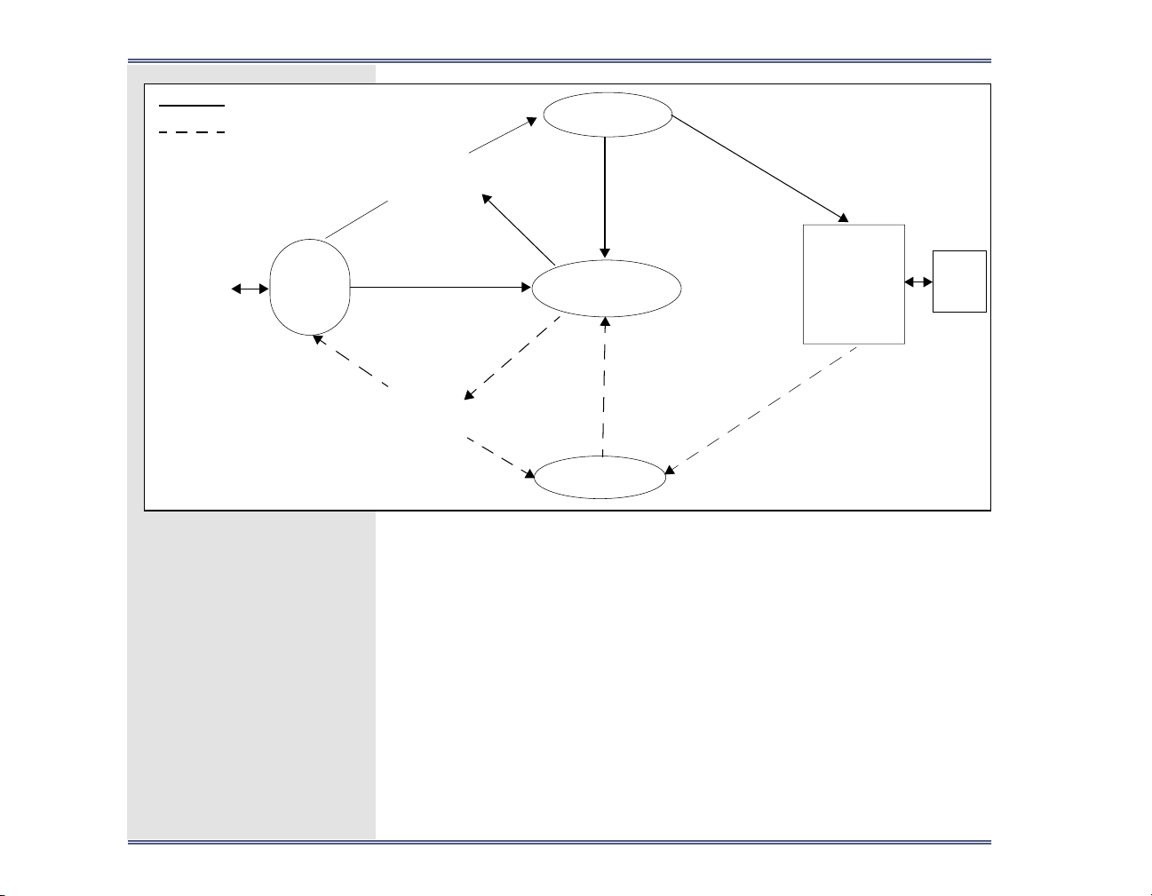
Architecture Server Architecture
Agent
Message from Agent
Message from Device
XGUIDE
Client
message queue
Guide Server
Guide server
Guide server
message
queue
Database server
message queue
Database server
message queue
Database Server
Database
server
message
queue
Switch Server
message queue
Telephony
Device
Switch
Switch server
message queue
IVR
Figure 2-2. Telephony Gateway Communication
EDGE Telephony Gateway communication consists of the following
elements:
Database
server
A member of the generic set of telephony IPC servers
for the Dialer Gateways, Davox, the EDGEdial plug-in
and TMI. Processes requests from the guide server and
the switch server and interacts with the EDGE database
files.
Telephony Gateway Reference Manual 25

Architecture Server Architecture
Telephony Servers
Guide server
Message
Queues
Switch server
Telephony
A member of the generic set of telephony IPC servers.
Processes requests from EDGE operations (XGUIDE) by
sending messages to the telephony device.
A transport mechanism for IPC messages coming from
an IPC server.
A member of the generic set of telephony IPC servers.
Processes responses from the telephony device.
The CTI equipment that is interfaced with EDGE.
device
XGUIDE
The EDGE Operations guide. This represents commands
executed by agents from the guide.
For more information on the telephony gateway communication
process, see the section Server Architecture Integration.
All server side telephony communication between EDGE and the
telephony device is performed using telephony servers. All gateways
use the guide server and switch server; the database server is also
used with the Dialer gateways, the Davox gateway, the EDGEdial
plug-in, and TMI. Together, the guide, switch, and database servers
are termed the generic set of telephony servers. Some gateways use
additional servers. The following telephony servers are described in
this section:
• Generic Set of Telephony Servers.
Telephony Gateway Reference Manual 26

Architecture Server Architecture
• CV/LAN Server.
• Data Server.
• Host-Based Router Server.
• IVR Gateway Server.
• Secondary Database Server.
• EDGEdial Server.
• TMI Server.
With the exception of the CV/LAN server and TMI server, if additional
servers are used, any actions taken on the generic set of telephony
servers affect them as well; for example, all servers are terminated
when the generic set of servers is terminated. The CV/LAN and TMI
servers are started and stopped separately.
Each telephony server writes the messages it is sending and receiving into its own log file. For example, when an agent executes a Dial
command in a guide, the message to dial a call is sent to the guide
server, and written to a log file for the guide server (guide.log0). For
more information on log files, see the section Telephony Logs.
Telephony Gateway Reference Manual 27

Architecture Server Architecture
Generic Set of Telephony Servers
The Guide server, Switch server, and Database server make up the
generic set of telephony servers.
One generic set of telephony servers communicates with one telephony device. EDGE supports 4096 sets of telephony servers running
concurrently per machine. Each set of servers must be identified by a
unique number from 0 to 4095, called the telephony server number.
(The telephony server number is specified in the telephony device
configuration. For more information, see the section Device.)
A generic set of telephony servers can be optionally started with the
first telephony operation; for example, when the first agent logs into
EDGE in telephony mode. The set of servers is optionally stopped
when the last agent logs out of telephony mode. For information on
optional startup and shutdown, see the section Device.
When a generic set of telephony servers is running, the following
processes run on the EDGE system, one for each server:
tpserver
tpserver
Telephony Gateway Reference Manual 28
The server process for the guide server.
The server process for the switch server. The process
has the same name as the guide server because it is
forked from the guide server, but the process ID number for each tpserver process will be different.

Architecture Server Architecture
tpdb_server
For the Dialer gateways, Davox, the EDGEdial plug-in,
and TMI, the server process for the database server.
tpserver Command
The tpserver command can be executed explicitly from the command line or implicitly using the TELEPHONY verb Update Telephony
Servers command to:
• Stop the telephony servers.
• Restart the telephony servers.
• Move the current telephony logs to another name and report
new information to empty log files.
• Change the maximum size of the telephony logs.
• Change the destination of any fatal error message returned
from the set of telephony servers.
• Flush the telephony server client queue of redundant messages.
The tpserver command is also used by EDGE operations and tasks to
start the generic set of telephony servers.
Note: The telephony servers can only be started from EDGE operations
or tasks, not from the command line.
Telephony Gateway Reference Manual 29

Architecture Server Architecture
All of the tpserver command options can be used with a set of telephony servers that are already running or when restarting the servers.
Syntax
tpserver -z {server-id} {options}
options The following options can be specified:
–C
path
–D
-d
-f
Specifies the path to the console that the set of
servers uses to report critical error messages. The
default path is /dev/console.
Writes the contents of shared memory to a file
called tpshmemn, where n corresponds with the
telephony server number.
Only available from the command line.
Displays a list of all running HBR servers and a list
of the current configuration properties (for example, the minimum number of servers, and maximum number of servers).
Only available from the command line.
Flushes the client queue of redundant messages.
See client queue maintenance.
Telephony Gateway Reference Manual 30
 Loading...